Embed Size (px)
Citation preview

Hydraulic Design • Culverts
Chapter 4
169
INTRODUCTIONMany millions of dollars are spent annually on culverts, storm drains and subdrains, allvital to the protection of streets, highways and railroads. If inadequately sized, they canjeopardize the roadway and cause excessive property damage and loss of life. Over designmeans extravagance. Engineering can find an economical solution.
Topography, soil and climate are extremely variable, so drainage sites should be designedindividually from reasonably adequate data for each particular site. In addition, thedesigner is advised to consult with those responsible for maintaining drainage structuresin the area. One highway engineer comments:
With the exception of the riding qualities of the traveled way, no other singleitem requires as much attention on the part of maintenance personnel as high-way culverts. Many of the problems of culvert maintenance stem from the factthat designers in all too many instances consider that culverts will be requiredto transport only clear water. This is a condition hardly ever realized in prac-tice, and in many instances storm waters may be carrying as much as 50 percentdetrimental material. A rapid change in grade line at the culvert entrance cancause complete blockage of the culvert. This results in overflow across the high-way and in some cases, especially where high fills are involved, the intense stat-ic pressure results in loss of the embankment.
HYDRAULICS OF OPEN DRAINAGE CHANNELS
GeneralBefore designing culverts and other drainage structures, one should consider the designof ditches, gutters, chutes, median swales and other channels leading to these structures.(See Figure 4.1).
Rainfall and runoff, once calculated, are followed by the design of suitable channels tohandle the peak discharge with minimum erosion, maintenance and hazard to traffic. TheAASHTO publication "A Policy on Geometric Design of Highways and Streets" states:"The depth of channels should be sufficient to remove the water without saturation ofthe pavement subgrade. The depth of water that can be tolerated, particularly on flatchannel slopes, depends upon the soil characteristics. In open country, channel sideslopes of 5:1 or 6:1 are preferable in order to reduce snow drifts." Systematic mainte-nance is recognized as essential to any drainage channel. Therefore maintenance shouldbe considered in the design of all channels.
CHAPTERf o u r

Chapter 4
170
Chezy EquationChezy developed a basic hydraulic relationship for determining the flow of water, partic-ularly in open channels. It is as follows:
Q= AV
if: V = c
then: Q= Ac
where: Q = discharge, ft3/sA = cross-sectional area of flow, ft2
V = mean velocity of flow, ft/sc = coefficient of roughness, depending upon the surface over
which water is flowing, ft1/2/s
R = hydraulic radius, ft
=
WP = wetted perimeter (length of wetted contact between water and its containing channel), ft
S = slope, or grade, ft/ft
This fundamental equation is the basis of most capacity formulations.
AWP
RS
RS
Corrugated Steel Pipe Design Manual
Types of roadside drainage channels.Figure 4.1

Chapter 4
171
Manning’s EquationManning’s equation, published in 1890, gives the value of c in the Chezy equation as:
c =1.486
where: n = coefficient of roughness (see Tables 4.1 and 4.2)
R1/6
n
Hydraulic Design • Culverts
Table 4.1
Manning’s n for constructed channels
Types of channel and description n1. LINED OR BUILT-UP
A. Concrete - Trowel Finish . . . . . . . . . . . . . . . . . . . . . . . . . . . . . . . . . . . . . . . . . . . . . . . . . . . . . . . . . . . 0.013
B. Concrete - Float Finish. . . . . . . . . . . . . . . . . . . . . . . . . . . . . . . . . . . . . . . . . . . . . . . . . . . . . . . . . . . . . 0.015
C. Concrete - Unfinished . . . . . . . . . . . . . . . . . . . . . . . . . . . . . . . . . . . . . . . . . . . . . . . . . . . . . . . . . . . . . 0.017
D. Gunite - Good Section. . . . . . . . . . . . . . . . . . . . . . . . . . . . . . . . . . . . . . . . . . . . . . . . . . . . . . . . . . . . . 0.019
E. Gravel Bottom with sides of:
1) Formed Concrete. . . . . . . . . . . . . . . . . . . . . . . . . . . . . . . . . . . . . . . . . . . . . . . . . . . . . . . . . . . . . . 0.020
2) Random Stone in Mortar . . . . . . . . . . . . . . . . . . . . . . . . . . . . . . . . . . . . . . . . . . . . . . . . . . . . . . 0.023
3) Dry Rubble or Rip Rap . . . . . . . . . . . . . . . . . . . . . . . . . . . . . . . . . . . . . . . . . . . . . . . . . . . . . . . . . 0.033
2. EXCAVATED OR DREDGED - EARTH
A. Straight and Uniform
1) Clean, Recently Completed . . . . . . . . . . . . . . . . . . . . . . . . . . . . . . . . . . . . . . . . . . . . . . . . . . . . 0.018
2) Clean, After Weathering. . . . . . . . . . . . . . . . . . . . . . . . . . . . . . . . . . . . . . . . . . . . . . . . . . . . . . . . 0.022
3) Gravel, Uniform Section, Clean . . . . . . . . . . . . . . . . . . . . . . . . . . . . . . . . . . . . . . . . . . . . . . . . . 0.025
4) With Short Grass, Few Weeds . . . . . . . . . . . . . . . . . . . . . . . . . . . . . . . . . . . . . . . . . . . . . . . . . . 0.027
B. Winding and Sluggish
1) No Vegetation . . . . . . . . . . . . . . . . . . . . . . . . . . . . . . . . . . . . . . . . . . . . . . . . . . . . . . . . . . . . . . . . . 0.025
2) Grass, Some Weeds . . . . . . . . . . . . . . . . . . . . . . . . . . . . . . . . . . . . . . . . . . . . . . . . . . . . . . . . . . . . 0.030
3) Dense Weeds, Deep Channels. . . . . . . . . . . . . . . . . . . . . . . . . . . . . . . . . . . . . . . . . . . . . . . . . . 0.035
4) Earth Bottom and Rubble Sides . . . . . . . . . . . . . . . . . . . . . . . . . . . . . . . . . . . . . . . . . . . . . . . . 0.030
5) Stony Bottom and Weedy Banks . . . . . . . . . . . . . . . . . . . . . . . . . . . . . . . . . . . . . . . . . . . . . . . 0.035
6) Cobble Bottom and Clean Sides. . . . . . . . . . . . . . . . . . . . . . . . . . . . . . . . . . . . . . . . . . . . . . . . 0.040
3. CHANNELS NOT MAINTAINED, WEEDS & BRUSH UNCUT
A. Dense Weeds, High as Flow Depth . . . . . . . . . . . . . . . . . . . . . . . . . . . . . . . . . . . . . . . . . . . . . . . . . 0.080
B. Clean Bottom, Brush on Sides. . . . . . . . . . . . . . . . . . . . . . . . . . . . . . . . . . . . . . . . . . . . . . . . . . . . . . 0.050
C. Same, Highest Stage of Flow. . . . . . . . . . . . . . . . . . . . . . . . . . . . . . . . . . . . . . . . . . . . . . . . . . . . . . . 0.070
D. Dense Brush, High Stage . . . . . . . . . . . . . . . . . . . . . . . . . . . . . . . . . . . . . . . . . . . . . . . . . . . . . . . . . . 0.100
Chapter 4
172
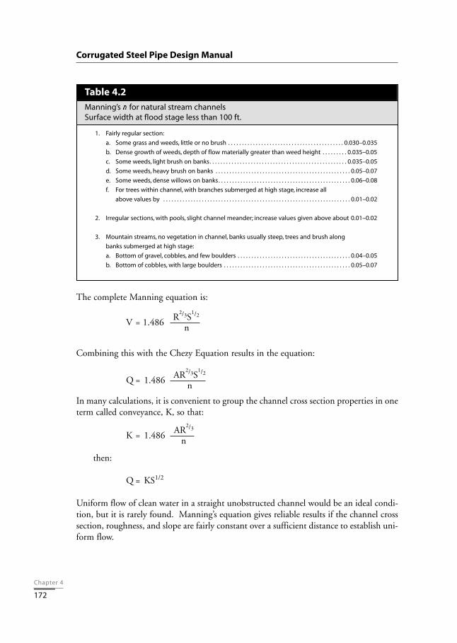
The complete Manning equation is:
V = 1.486
Combining this with the Chezy Equation results in the equation:
Q = 1.486
In many calculations, it is convenient to group the channel cross section properties in oneterm called conveyance, K, so that:
K = 1.486
then:
Q = KS1/2
Uniform flow of clean water in a straight unobstructed channel would be an ideal condi-tion, but it is rarely found. Manning’s equation gives reliable results if the channel crosssection, roughness, and slope are fairly constant over a sufficient distance to establish uni-form flow.
AR2/3
n
AR2/3S
1/2
n
R2/3S
1/2
n
Corrugated Steel Pipe Design Manual
Table 4.2
Manning’s n for natural stream channelsSurface width at flood stage less than 100 ft.
1. Fairly regular section:
a. Some grass and weeds, little or no brush . . . . . . . . . . . . . . . . . . . . . . . . . . . . . . . . . . . . . . . . . . 0.030–0.035
b. Dense growth of weeds, depth of flow materially greater than weed height . . . . . . . . . 0.035–0.05
c. Some weeds, light brush on banks. . . . . . . . . . . . . . . . . . . . . . . . . . . . . . . . . . . . . . . . . . . . . . . . . . 0.035–0.05
d. Some weeds, heavy brush on banks . . . . . . . . . . . . . . . . . . . . . . . . . . . . . . . . . . . . . . . . . . . . . . . . . 0.05–0.07
e. Some weeds, dense willows on banks. . . . . . . . . . . . . . . . . . . . . . . . . . . . . . . . . . . . . . . . . . . . . . . . 0.06–0.08
f. For trees within channel, with branches submerged at high stage, increase all
above values by . . . . . . . . . . . . . . . . . . . . . . . . . . . . . . . . . . . . . . . . . . . . . . . . . . . . . . . . . . . . . . . . . . . . 0.01–0.02
2. Irregular sections, with pools, slight channel meander; increase values given above about 0.01–0.02
3. Mountain streams, no vegetation in channel, banks usually steep, trees and brush along
banks submerged at high stage:
a. Bottom of gravel, cobbles, and few boulders . . . . . . . . . . . . . . . . . . . . . . . . . . . . . . . . . . . . . . . . . 0.04–0.05
b. Bottom of cobbles, with large boulders . . . . . . . . . . . . . . . . . . . . . . . . . . . . . . . . . . . . . . . . . . . . . . 0.05–0.07

Chapter 4
173
The Use of Charts and TablesWhile design charts for open-channel flow reduce computational effort, they cannotreplace engineering judgment and a knowledge of the hydraulics of open-channel flowand flow through conduits with a free water surface.
Design charts contain the channel properties (area and hydraulic radius) of many chan-nel sections and tables of velocity for various combinations of slope and hydraulic radius.Their use is explained in the following examples:
Example 1Given: A trapezoidal channel of straight alignment and uniform cross section in earth
with a bottom width of 2 feet, side slopes at 1:1, a channel slope of 0.003 ft/ft,and a normal depth of water of 1 foot.
Find: Velocity and discharge.
Solution:1. Based on Table 4.1, for an excavated channel in ordinary earth, n is taken
as 0.02.2. Cross-sectional area, A, is 3 ft2 [1 * (2 + 1 * 1)].3. Wetted perimeter, WP, is 4.83 ft [2 + 2 *( 1 * (12+12)1/2)].4. Hydraulic radius, R, is 0.62 ft [3 / 4.83].5. Using the nomograph in Figure 4.2, lay a straight edge between the outer
scales at the values of S = 0.003 and n = 0.02. Mark where the straight edge intersects the turning line.
6. Place the straight edge to line up the point on the turning line and the hydraulic radius of 0.62 ft.
7. Read the velocity, V, of 2.9 ft/s on the velocity scale.8. Discharge, Q, is 8.7 ft3/s[3 * 2.9].
Figure 4.3 provides the means to calculate a trapezoidal channel capacity for a specificbottom width, channel slope, side slope, n value and a variety of flow depths. For a givendrainage project, these variables are either known or determined using known site param-eters through trial and error. The flow rate, Q, can then be calculated.
Hydraulic Design • Culverts

Chapter 4
174
Corrugated Steel Pipe Design Manual
Nomograph for solution of Manning's equation.Figure 4.2

Chapter 4
175
Hydraulic Design • Culverts
Capacity of trapezoidal channel.Figure 4.3

Chapter 4
176
Example 2
Given: Bottom width, b = 20 ftSide slopes @ 2:1, z = 2Roughness coefficient, n = 0.030(from Table 4.2 for grass and weeds, no brush)Channel slope, S = 0.002 ft/ftDepth to bottom width ratio, d/b = 0.6 (flood stage depth)
Find: Depth of flow, d, and flow rate, Q.
Solution:1. Depth, d = 12 ft [0.6 * 20]2. From Figure 4.3:
= 0.92
3. So:= 0.92
4. And: Q = 4042 ft3/s
If the resulting design is not satisfactory, the channel parameters are adjusted and thedesign calculations are repeated.
Safe VelocitiesThe ideal situation is one where the velocity will cause neither silt deposition nor erosion.For the design of a channel, the approximate grade can be determined from a topograph-ic map, from the plan profiles or from both.
To prevent the deposition of sediment, the minimum gradient for earth and grass-linedchannels should be about 0.5 percent and that for smooth paved channels about 0.35 per-cent.
Convenient guidelines for permissible velocities are provided in Tables 4.3 and 4.4. Morecomprehensive design data may be found in HEC 15, Design of Stable Channels withFlexible Linings, U.S. Federal Highway Administration (FHWA).
Q (0.030)208/3 (0.002)1/2
Q • nb8/3 S1/2
Corrugated Steel Pipe Design Manual

Chapter 4
177
Channel ProtectionCorrugated steel flumes or chutes and pipe spillways are favored solutions for channelprotection, especially in wet, unstable or frost susceptible soils. They should be anchoredto prevent undue shifting. This will also protect against buoyancy and uplift, which canoccur especially when the pipe is empty. Cutoff walls or collars are used to prevent under-mining.
If the mean velocity exceeds the permissible velocity for the particular type of soil, thechannel should be protected from erosion. Grass linings are valuable where grass growthcan be supported. Ditch bottoms may be sodded or seeded with the aid of temporaryquick growing grasses, mulches or erosion control blankets. Grass may also be used incombination with other more rigid types of linings, where the grass is on the upper bankslopes and the rigid lining is on the channel bottom. Linings may consist of stone whichis dumped, hand placed or grouted, preferably laid on a filter blanket of gravel or crushedstone and a geotextile.
Hydraulic Design • Culverts
Table 4.3
Comparison of water velocity limits and tractive force valuesfor the design of stable channels
Water TransportingFor Clear Water Colloidal Silts
Tractive* Tractive*Velocity Force Velocity Force
Material n ft/sec Ib/ft2 ft/sec Ib/ft2
Fine sand colloidal . . . . . . . . . . . . . . . . . . . . . . . . . . . . . 0.020 1.50 0.027 2.50 0.075Sandy loam noncolloidal . . . . . . . . . . . . . . . . . . . . . . . 0.020 1.75 0.037 2.50 0.075Silt loam noncolloidal . . . . . . . . . . . . . . . . . . . . . . . . . . 0.020 2.00 0.048 3.00 0.11Alluvial silts noncolloidal . . . . . . . . . . . . . . . . . . . . . . . 0.020 2.00 0.048 3.50 0.15Ordinary firm loam . . . . . . . . . . . . . . . . . . . . . . . . . . . . . 0.020 2.50 0.075 3.50 0.15Volcanic ash . . . . . . . . . . . . . . . . . . . . . . . . . . . . . . . . . . . . 0.020 2.50 0.075 3.50 0.15Stiff clay very colloidal . . . . . . . . . . . . . . . . . . . . . . . . . . 0.025 3.75 0.26 5.00 0.46Alluvial silts colloidal . . . . . . . . . . . . . . . . . . . . . . . . . . . 0.025 3.75 0.26 5.00 0.46Shales and hardpans . . . . . . . . . . . . . . . . . . . . . . . . . . . 0.025 6.00 0.67 6.00 0.67Fine gravel . . . . . . . . . . . . . . . . . . . . . . . . . . . . . . . . . . . . . 0.020 2.50 0.075 5.00 0.32Graded loam to cobbles when non-colloidal . . . . 0.030 3.75 0.38 5.00 0.66Graded silts to cobbles when colloidal . . . . . . . . . . 0.030 4.00 0.43 5.50 0.80Coarse gravel noncolloidal. . . . . . . . . . . . . . . . . . . . . . 0.025 4.00 0.30 6.00 0.67Cobbles and shingles . . . . . . . . . . . . . . . . . . . . . . . . . . . 0.035 5.00 0.91 5.50 1.10
* Tractive force or shear is the force which the water exerts on the periphery of a channel due to the motionof the water. The tractive values shown were computed from velocities given by S. Fortier and Fred C. Scobeyand the values of n shown.
The tractive force values are valid for the given materials regardless of depth. For depths greater than 3 ft,higher velocities can be allowed and still have the same tractive force.
From U.S. Bureau of Reclamation, Report No. Hyd-352, 1952, 60 pp.

Chapter 4
178
Asphalt and concrete lined channels are used for steep erodible channels. Ditch checksare an effective means of decreasing the velocity and thereby the erodibility of the soil.High velocities, where water discharges from a channel, must be considered and provi-sions be made to dissipate the excess energy.
HYDRAULICS OF CULVERTS
IntroductionCulvert design has not yet reached the stage where two or more individuals will alwaysarrive at the same answer, or where actual service performance matches the designer’sexpectation. The engineer’s interpretation of field data and hydrology is often influencedby personal judgement, based on experience in a given locality. However, hydrology andhydraulic research are closing the gap to move the art of culvert design closer to becom-ing a science.
Corrugated Steel Pipe Design Manual
Table 4.4
Maximum permissible velocities in vegetal-lined channels
Permissible Velocitya
Erosion Resistant Easily ErodedSlope Range Soils Soils
Cover Average, UniformPercent ft/sec ft/sec
Stand, Well Maintained
0 - 5 8 6Bermudagrass 5 - 10 7 5
over 10 6 4
Buffalograss 0 - 5 7 5Kentucky bluegrass 5 - 10 6 4Smooth brome over 10 5 3Blue grama
Grass mixtureb 5 - 10 5 44 3
Lespedeza sericeaWeeping lovegrassYellow bluestem 0 - 5 3.5 2.5AlfalfaCrabgrass
Common lespedezab
Sudangrassb 0 - 5c 3.5 2.5
a From “Engineering Field Manual” USDA - Soil Conservation Service, 1979, (now Natural ResourceConservation Service).
b Annuals—used on mild slopes or as temporary protection until permanent covers are established .c Use on slopes steeper than 5 percent is not recommended.

Chapter 4
179
Up to this point, the design procedure has consisted of (1) collecting field data, (2) com-piling facts about the roadway, and (3) making a reasonable estimate of flood discharge.The next step is to design an economical corrugated steel structure to handle the flow,including debris, with minimum damage to the slope or culvert barrel. Treatment of theinlet and outlet ends of the structure must also be considered.
What Makes a Good Culvert?An ASCE Task Force on Hydraulics of Culverts offers the following recommendations for"Attributes of a Good Highway Culvert":
1. The culvert, appurtenant entrance and outlet structures should properly takecare of water, bed load, and floating debris at all stages of flow.
2. It should cause no unnecessary or excessive property damage.
3. Normally, it should provide for transportation of material without detrimentalchange in flow pattern above and below the structure.
4. It should be designed so that future channel and highway improvement can bemade without too much loss or difficulty.
5. It should be designed to function properly after fill has caused settlement.
6. It should not cause objectionable stagnant pools in which mosquitoes maybreed.
7. It should be designed to accommodate increased runoff occasioned by anticipat-ed land development.
8. It should be economical to build, hydraulically adequate to handle design dis-charge, structurally durable and easy to maintain.
9. It should be designed to avoid excessive ponding at the entrance which maycause property damage, accumulation of drift, culvert clogging, saturation offills, or detrimental upstream deposits of debris.
10. Entrance structures should be designed to screen out material which will notpass through the culvert, reduce entrance losses to a minimum, make use of thevelocity of approach in so far as practicable, and by use of transitions andincreased slopes, as necessary, facilitate channel flow entering the culvert.
11. The design of the culvert outlet should be effective in re-establishing tolerablenon-erosive channel flow within the right-of-way or within a reasonably shortdistance below the culvert.
Hydraulic Design • Culverts

Chapter 4
180
12. The outlet should be designed to resist undermining and washout.
13. Energy dissipaters, if used, should be simple, easy to build, economical and rea-sonably self-cleaning during periods of easy flow.
Design MethodThe culvert design process should strive for a balanced result. Pure fluid mechanicsshould be combined with practical considerations to help assure satisfactory performanceunder actual field conditions. This includes due consideration of prospective mainte-nance and the handling of debris.
The California Department of Transportation uses an excellent method of accomplishingthis, which has worked well for many years. Other states and agencies have used similarapproaches. California culvert design practice establishes the following:
Criteria for Balanced Design
The culvert shall be designed to discharge
a) a 10 year flood without static head at the entrance, and b) a 100 year flood utilizing the available head at the entrance.
This approach lends itself well to most modern design processes and computer programssuch as those published by the U.S. FHWA. It provides a usable rationale for determin-ing a minimum required waterway area. This design method is highly recommended andis followed here in conjunction with FHWA charts.
The permissible height of water at the inlet controls hydraulic design. This should bedetermined and specified for each site based on the following considerations:
1. Risk of overtopping the embankment and the resulting risk to human life.
2. Potential damage to the roadway, due to saturation of the embankment, andpavement disruption due to freeze-thaw.
3. Traffic interruptions.
4. Damage to adjacent or upstream property, or to the channel or flood plain envi-ronment.
5. Intolerable discharge velocities, which can result in scour and erosion.
6. Deposition of bed load and/or clogging by debris on recession of flow.
Corrugated Steel Pipe Design Manual

Flow Conditions and DefinitionsCulverts considered here are circular pipes and pipe arches with a uniform barrel cross-section throughout.
There are two major types of culvert flow conditions:
Inlet Control – A culvert flowing in inlet control is characterized by shallow, high veloci-ty flow categorized as supercritical. Inlet control flow occurs when the culvert barrel iscapable of conveying more flow than the inlet will accept. The control section is near theinlet, and the downstream pipe and flow have no impact on the amount of flow throughthe pipe. Under inlet control, the factors of primary importance are (1) the cross-section-al area of the barrel, (2) the inlet configuration or geometry, and (3) the headwater eleva-tion or the amount of ponding upstream of the inlet (see Figure 4.4). The barrel slopealso influences the flow under inlet control, but the effect is small and it can be ignored.
Outlet Control – A culvert flowing in outlet control is characterized by relatively deep,lower velocity flow categorized as subcritical. Outlet control flow occurs when the cul-vert barrel is not capable of conveying as much flow as the inlet opening will accept. Thecontrol section is at the outlet of the culvert. In addition to the factors considered forinlet control, factors that must be considered for outlet control include (1) the tailwaterelevation in the outlet channel, (2) the barrel slope, (3) the barrel roughness, and (4) thelength of the barrel (see Figure 4.5). Chapter 4
181
Hydraulic Design • Culverts
Inlet control flow regimes.Figure 4.4

Chapter 4
182
Hydraulics of Culverts in Inlet ControlInlet control means that the discharge capacity is controlled at the entrance by the head-water depth, cross-sectional area and type of inlet edge. The roughness, length, and out-let conditions are not factors in determining the culvert capacity.
Sketches A and B in Figure 4.4 show unsubmerged and submerged projecting inletsrespectively. Inlet control performance is classified by these two regimes (unsubmergedflow and submerged flow) as well as a transition region between them.
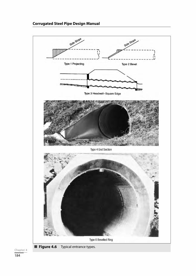
Entrance loss depends upon the geometry of the inlet edge and is expressed as a fractionof the velocity head. Research with models and prototype testing have resulted in coef-ficients for various types of inlets, as shown in Table 4.5 and Figure 4.6.
Corrugated Steel Pipe Design Manual
Outlet control flow regimes.Figure 4.5

The model testing and prototype measurements also provide information used to devel-op equations for unsubmerged and submerged inlet control flow. The transition zone ispoorly defined, but it is approximated by plotting the two flow equations and connect-ing them with a line which is tangent to both curves. These plots, done for a variety ofstructure sizes, are the basis for constructing the design nomographs included in thisdesign manual.
In the nomographs, the headwater depth (HW) is the vertical distance from the culvertinvert (bottom) at the entrance to the energy grade line of the headwater pool. It there-fore includes the approach velocity head. The velocity head tends to be relatively smalland is often neglected. The resulting headwater depth is therefore conservative and theactual headwater depth would be slightly less than the calculated value. If a more accu-rate headwater depth is required, the approach velocity head should be subtracted fromthe headwater depth determined using the nomographs.
Hydraulics of Culverts in Outlet ControlOutlet control means that the discharge capacity is controlled at the outlet by the tailwa-ter depth or critical depth, and it is influenced by such factors as the slope, wall rough-ness and length of the culvert. The following energy balance equation contains the vari-ables that influence the flow through culverts flowing under outlet control:
where: L = length of culvert, ftSo = slope of barrel, ft/ftHW = headwater depth, ftV1 = approach velocity, ft/sg = gravitational constant = 32.2 ft/s2
ho = outlet datum, ftH = head, ftV2 = downstream velocity, ft/s
V12 V2
2
L•So + HW + = ho + H + 2g 2g
Table 4.5
Entrance loss coefficients for corrugated steel pipes and pipe arches
Chapter 4
183
Hydraulic Design • Culverts
EntranceInlet End of Culvert Type Coefficient, ke
Projecting from fill (no headwall) 1 0.9Mitered (beveled) to conform to fill slope 2 0.7Headwall or headwall and wingwalls square-edge 3 0.5End-Section conforming to fill slope 4 0.5Headwall rounded edge 5 0.2Beveled Ring 6 0.25
Chapter 4
184
Corrugated Steel Pipe Design Manual
Typical entrance types.Figure 4.6

Chapter 4
185
The headwater depth (HW) is the vertical distance from the culvert invert at the entrance(where the entrance is that point in the pipe where there is the first full cross-section) tothe surface of the headwater pool.
As discussed under inlet control hydraulics, the water surface and energy grade line areusually assumed to coincide at the entrance; the approach velocity head is ignored. Thesame can be said for the downstream velocity head. That being the case, the approachvelocity head and downstream velocity head terms in the above equation would bedropped and the equation would take the form below. Note that this equation has beenorganized to provide the resulting headwater depth.
HW = ho + H – L•So
The head, or energy (Figures 4.7 through 4.9) required to pass a given quantity of waterthrough a culvert flowing in outlet control, is made up of a (1) entrance loss, (2) frictionloss, and (3) exit loss.
Hydraulic Design • Culverts
Definition of terms in energy balance equation.Figure 4.7
Terms of the energy balance equation related to a high tailwater condition.
Figure 4.8
Chapter 4
186
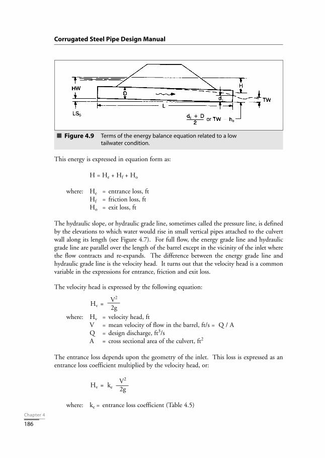
This energy is expressed in equation form as:
H = He + Hf + Ho
where: He = entrance loss, ftHf = friction loss, ftHo = exit loss, ft
The hydraulic slope, or hydraulic grade line, sometimes called the pressure line, is definedby the elevations to which water would rise in small vertical pipes attached to the culvertwall along its length (see Figure 4.7). For full flow, the energy grade line and hydraulicgrade line are parallel over the length of the barrel except in the vicinity of the inlet wherethe flow contracts and re-expands. The difference between the energy grade line andhydraulic grade line is the velocity head. It turns out that the velocity head is a commonvariable in the expressions for entrance, friction and exit loss.
The velocity head is expressed by the following equation:
where: Hv = velocity head, ftV = mean velocity of flow in the barrel, ft/s = Q / AQ = design discharge, ft3/sA = cross sectional area of the culvert, ft2
The entrance loss depends upon the geometry of the inlet. This loss is expressed as anentrance loss coefficient multiplied by the velocity head, or:
where: ke = entrance loss coefficient (Table 4.5)
V2
Hv = ke 2g
V2
Hv = 2g
Corrugated Steel Pipe Design Manual
Terms of the energy balance equation related to a low tailwater condition.
Figure 4.9

Chapter 4
187
The friction loss is the energy required to overcome the roughness of the culvert barreland is expressed by the following equation:
where: n = Manning’s friction factor (see Tables 4.6 and 4.7)R = hydraulic radius, ft = A / WPWP = wetted perimeter, ft
The exit loss depends on the change in velocity at the outlet of the culvert. For a suddenexpansion, the exit loss is expressed as:
As discussed previously, the downstream velocity head is usually neglected, in which casethe above equation becomes the equation for the velocity head:
Substituting in the equation for head we get (for full flow):
Nomographs have been developed and can be used for solving this equation. Note thatthese nomographs provide the head, whereas the inlet control nomographs provide theheadwater depth. The head is then used to calculate the headwater depth by solving thepreceding equation for HW (including the terms of ho and L•So).
This equation was developed for the full flow condition, which is as shown in Figure 4.5A. It is also applicable to the flow condition shown in Figure 4.5 B.
Backwater calculations are required for the partly full flow conditions shown in Figure4.5 C and D. These calculations begin at the downstream water surface and proceedupstream to the entrance of the culvert and the headwater surface. The downstreamwater surface is based on either the critical depth or the tailwater depth, whichever isgreater (Figure 4.9).
29n2L V2
Ho = ke+ + 1R1.33 2g{ }
V2
Ho = Hv =2g
V2 V22
Ho =1.0 -2g 2g[ ]
29n2L V2
Hf =R 1.33 2g{ }
Hydraulic Design • Culverts

Chapter 4
188
Corrugated Steel Pipe Design Manual
Tab
le 4
.6
Valu
es o
f co
effic
ien
t o
f ro
ug
hn
ess
(Man
nin
g's
n) fo
r st
and
ard
co
rru
gat
ed s
teel
pip
es
2-2/
3 x
1/2
Hel
ical
Co
rru
gat
ion
,Pit
ch x
Ris
e (in
.)
An
nu
lar
1-1/
2 x
1/4
2-2/
3 x
1/2
Flo
win
gFi
nis
hC
orr
ug
atio
nD
iam
eter
(in
.)
All
Dia
.8
1012
1518
2430
3642
48≥
54
Full
Un
pav
ed0.
024
0.01
20.
014
0.01
10.
012
0.01
30.
015
0.01
70.
018
0.01
90.
020
0.02
1
Full
25%
pav
ed0.
021
0.01
40.
016
0.01
70.
018
0.02
00.
019
Part
Fu
llU
np
aved
0.02
70.
012
0.01
30.
015
0.01
70.
019
0.02
00.
021
0.02
20.
023
All
Pip
e A
rch
Sp
an x
Ris
e (in
.)
Pip
e A
rch
es17
x 1
321
x 1
528
x 2
035
x 2
442
x 2
949
x 3
357
x 3
8≥
64 x
43
Full
Un
pav
ed0.
026
0.01
30.
014
0.01
60.
018
0.01
90.
020
0.02
10.
022
Part
Fu
llU
np
aved
0.02
90.
018
0.01
60.
021
0.02
30.
024
0.02
50.
025
0.02
6
3 x
1H
elic
al C
orr
ug
atio
n,P
itch
x R
ise
(in.)
An
nu
lar
3 x
1
Co
rru
gat
ion
Dia
met
er (i
n.)
All
Dia
.36
4248
5460
6672
≥ 78
Full
Un
pav
ed0.
027
0.02
20.
022
0.02
30.
023
0.02
40.
025
0.02
60.
027
Full
25%
Pav
ed0.
023
0.01
90.
019
0.02
00.
020
0.02
10.
022
0.02
20.
023
5 x
1H
elic
al C
orr
ug
atio
n,P
itch
x R
ise
(in.)
An
nu
lar
5 x
1
Co
rru
gat
ion
Dia
met
er (i
n.)
All
Dia
.48
5460
6672
≥ 78
Full
Un
pav
ed0.
025
0.02
20.
022
0.02
30.
024
0.02
40.
025
Full
25%
Pav
ed0.
022
0.01
90.
019
0.02
00.
021
0.02
10.
022
All
Dia
met
ers
Smo
oth
Inte
rio
r Pi
pe
(1)
0.01
2
No
te (1
):In
clu
des
fully
pav
ed,c
on
cret
e lin
ed.r
ibb
ed p
ipe
and
do
ub
le w
all p
ipe.

Chapter 4
189
The backwater calculations can be tedious and time consuming. Approximation meth-ods have therefore been developed for the analysis of partly full flow conditions.Backwater calculations have shown that a downstream extension of the full flow hydraulicgrade line, for the flow condition shown in Figure 4.5 C, intersects the plane of the cul-vert outlet cross section at a point half way between the critical depth and the top of theculvert. This is more easily envisioned as shown in Figure 4.9. It is possible to begin thehydraulic grade line at that datum point and extend the straight, full flow hydraulic gradeline to the inlet of the culvert. The slope of the hydraulic grade line is the full flow fric-tion slope:
If the tailwater elevation exceeds the datum point described above, the tailwater depth isused instead as the downstream starting point for the full flow hydraulic grade line.
The headwater depth is calculated by adding the inlet losses to the elevation of thehydraulic grade line at the inlet.
This method approximation works best when the culvert is flowing full for at least partof its length, as shown in Figure 4.5 C. If the culvert is flowing partly full for its wholelength, as shown in Figure 4.5 D, the results become increasingly inaccurate as the flowdepth decreases. The results are usually acceptable down to a headwater depth of aboutthree quarters of the structure rise. For lower headwater depths, backwater calculationsare required.
The outlet control nomographs can by used with this method of approximation. In thiscase, the head is added to the datum point elevation to obtain the headwater depth. Thismethod also works best when the culvert is flowing full for part of its length, and theresults are not as accurate for a culvert flowing partly full.
Hf 29n2 V2
Sn = =L R1.33 2g{ }
Hydraulic Design • Culverts
Table 4.7
Values of coefficient of roughness (Manning’s n) for structural plate pipe,6 in.x 2 in.corrugations
DiametersCorrugations
6 x 2 in. 5 ft 7 ft 10 ft 15ft
Plain – unpaved 0.033 0.032 0.030 0.028
25% Paved 0.028 0.027 0.026 0.024

Chapter 4
190
Research on Values of n for Helically Corrugated Steel PipeTests conducted on helically corrugated steel pipe, both round and pipe arch flowing fulland part full, demonstrate a lower coefficient of roughness compared to annularly corru-gated steel pipe. The roughness coefficient is a function of the corrugation helix angle(angle subtended between corrugation direction and centerline of the corrugated steelpipe), which determines the helically corrugated pipe diameter. A small helix angle asso-ciated with small diameter pipe, correlates to a lower roughness coefficient. Similarly, asthe helix angle increases with diameter, the roughness coefficient increases, approachingthe value associated with annularly corrugated pipe.
Values for 5 x 1 inch corrugations have been based on tests conducted using 6 x 2 inchand subsequently modified for the shorter pitch. Most published values of the coefficientof roughness, n, are based on experimental work conducted under controlled laboratoryconditions using clear or clean water. The test pipe lines are straight with smooth joints.However, design values should take into account the actual construction and service con-ditions, which can vary greatly for different drainage materials. Also, as noted on preced-ing pages, culvert or storm drain capacity under inlet control flow conditions is not affect-ed by the roughness of pipe material.
Field Studies on Structural Plate PipeModel studies by the U.S. Corps of Engineers, and analyses of the results by the U.S.Federal Highway Administration, have been the basis for friction factors of structuralplate pipe for many years. These values ranged from 0.0328 for 5 foot diameter pipe to0.0302 for 15 foot diameter pipe.
In 1968, the first full-scale measurements were made on a 1500 foot long 14 foot diam-eter structural plate pipe line in Lake Michigan. These measurements indicated a lowerfriction factor than those derived from the model studies. As a result, the recommendedvalues of Manning’s n for structural plate pipe of 10 foot diameter and larger have beenmodified as shown in Table 4.7. The values for the smaller diameters remain as they were.
HYDRAULIC COMPUTATIONSA balanced design approach is considered one in which the approach establishes a mini-mum opening required to pass, for example, a 10-year flood with no ponding. In thisexample, the 10-year discharge is established from hydrology data. The pipe size requiredto carry this flow, with no head at the entrance (HW/D = 1.0), is then determined fromnomographs. The designer uses the 10-year discharge to determine the pipe size requiredfor inlet control and for outlet control, and uses whichever is greater. This is typically theminimum required opening size for the culvert.
Corrugated Steel Pipe Design Manual

Chapter 4
191
Inlet ControlThe headwater (HW) for a given pipe flowing under inlet control can be determinedfrom Figures 4.10 through 4.17. Round pipes, pipe arches, and arches are included, asindicated.
These figures are first used to determine the pipe size required so there is no head at theentrance under a 10-year flood condition. Once a pipe size is chosen, the designer alsochecks that pipe to determine whether outlet control will govern (as described below),and makes pipe size adjustments accordingly.
The designer uses the selected pipe size to determine the headwater for specific entranceconditions for the 100-year flood discharge under inlet control. If this amount of head-water is acceptable, the chosen size is satisfactory for the full 100-year design dischargeunder inlet control. If the resulting headwater is too high, a larger size must be selectedbased on the maximum permissible headwater.
The values from the nomographs give the headwater in terms of a number of pipe rises(HW/D). The following equation is then used to calculate the headwater depth:
where: HWi= headwater depth under inlet control, ft
HW= headwater depth in number of pipe rises, from nomograph, ft/ft
D
D = diameter of pipe, or rise of arch or pipe arch, ft
HWHWi = • D
D
Hydraulic Design • Culverts
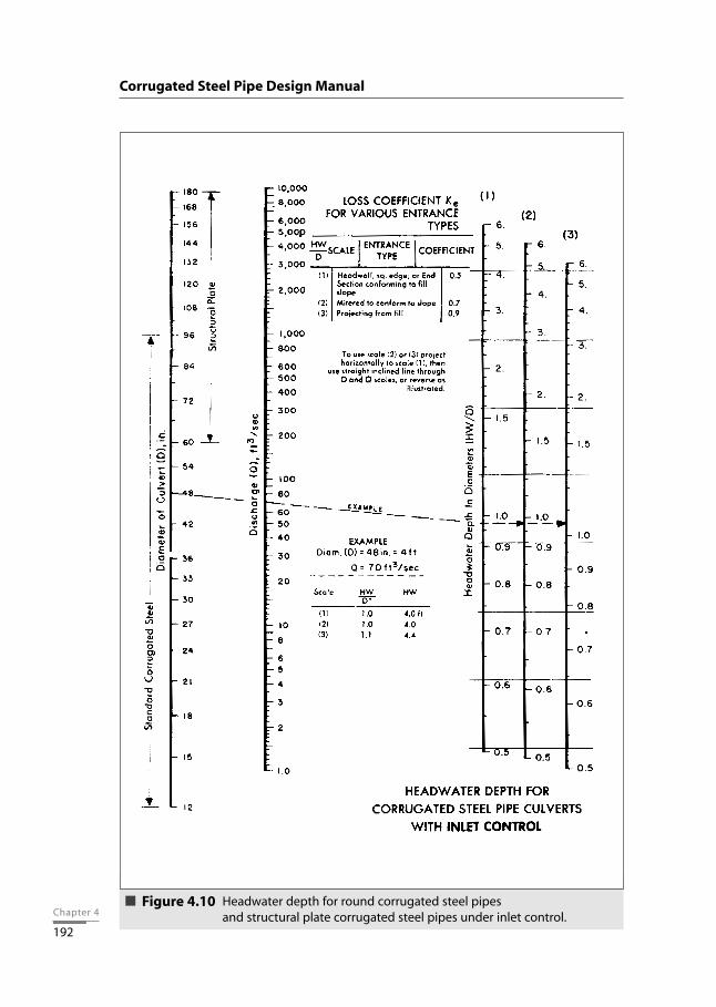
Headwater depth for round corrugated steel pipesand structural plate corrugated steel pipes under inlet control.
Figure 4.10Chapter 4
192
Corrugated Steel Pipe Design Manual

Chapter 4
193
Hydraulic Design • Culverts
Headwater depth for round corrugated steel pipes,with beveled ring headwall, under inlet control.
Figure 4.11
Chapter 4
194
Corrugated Steel Pipe Design Manual
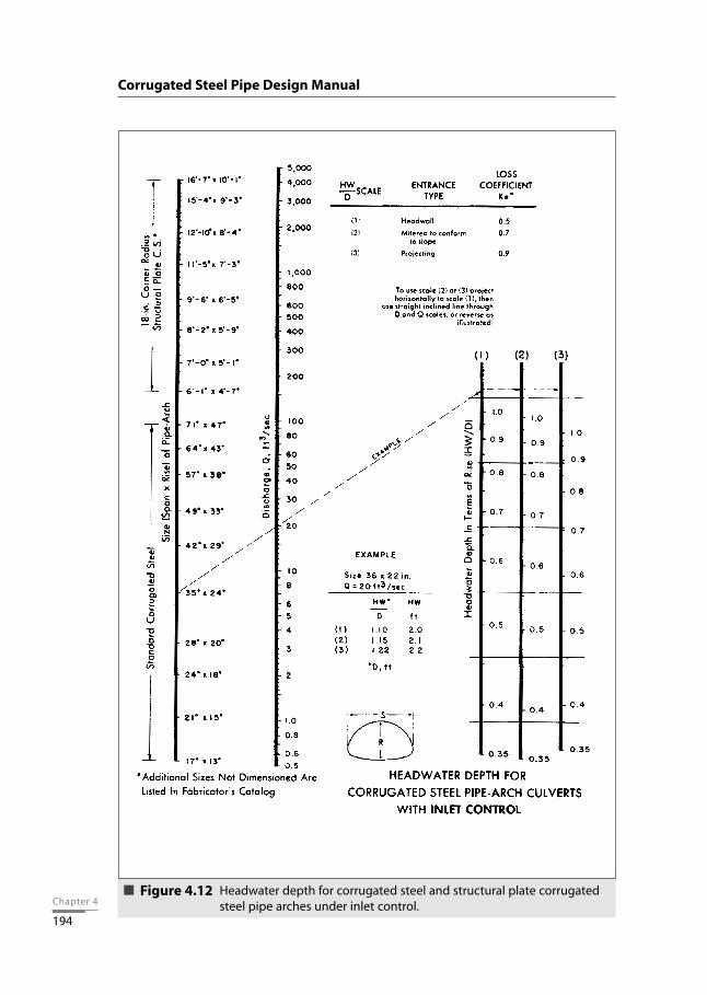
Headwater depth for corrugated steel and structural plate corrugatedsteel pipe arches under inlet control.
Figure 4.12
Chapter 4
195
Hydraulic Design • Culverts
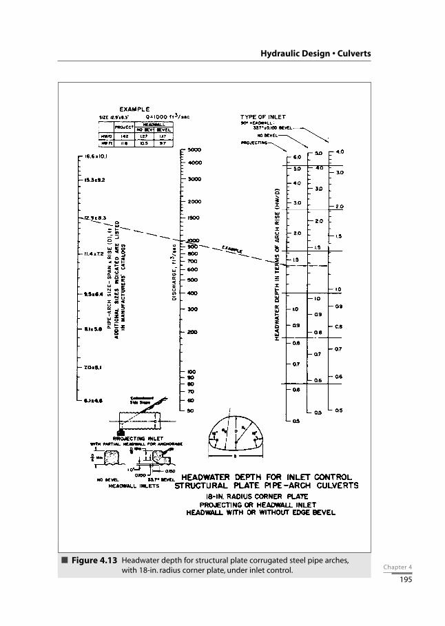
Headwater depth for structural plate corrugated steel pipe arches,with 18-in. radius corner plate, under inlet control.
Figure 4.13

Chapter 4
196
Corrugated Steel Pipe Design Manual
Headwater depth for structural plate corrugated steel pipe arches,with 31-in. radius corner plate, under inlet control.
Figure 4.14

Chapter 4
197
Hydraulic Design • Culverts
Headwater depth for structural plate corrugated steel arches,with 0.3 <= rise/span < 0.4, under inlet control.
Figure 4.15
Chapter 4
198
Corrugated Steel Pipe Design Manual
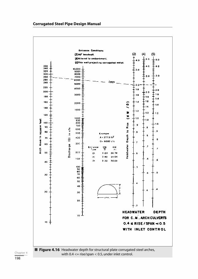
Headwater depth for structural plate corrugated steel arches,with 0.4 <= rise/span < 0.5, under inlet control.
Figure 4.16

Chapter 4
199
Hydraulic Design • Culverts
Headwater depth for structural plate corrugated steel arches,with 0.5 <= rise/span, under inlet control.
Figure 4.17
Chapter 4
200
Outlet ControlFigures 4.18 through 4.27 are used, with the pipe size selected for inlet control, to deter-mine the head loss, H. The head loss is then used in the following equation to determinethe headwater depth under outlet control. If the depth computed for outlet control isgreater than the depth determined for inlet control, then outlet conditions govern theflow conditions of the culvert and the higher headwater depth applies.
HWo = ho + H - L•So
where: HWo = headwater depth under outlet control, ftho = outlet datum, ft; the greater of the tailwater depth, TW,
or (dc + D)2
H = head, from nomograph, ftL = length of culvert barrel, ftSo = slope of culvert barrel, ft/ftTW = depth of flow in channel at culvert outlet, ftdc = critical depth, from Figures 4.28 through 4.31, ftD = diameter of pipe, or rise of arch or pipe arch, ft
Wall roughness factors (Manning’s n), on which the nomographs are based, are stated oneach figure. In order to use the nomographs for other values of n, an adjusted value forlength, L', is calculated using the equation below. This value is then used on the lengthscale of the nomograph, rather than the actual culvert length.
where L’ = adjusted length for use in nomographs, ftL = actual length, ftn’ = actual value of Manning’s nn = value of Manning’s n on which nomograph is based
Values of Manning’s n for standard corrugated steel pipe, which were listed in Table 4.6,are shown for convenience in Table 4.8, together with the corresponding length adjust-ment factors, . n’ 2
n( )
n’ 2L’ = L • n( )
Corrugated Steel Pipe Design Manual

Chapter 4
201
Values of Manning’s n for structural plate corrugated steel pipe, which were determinedin the 1968 full-scale field measurements and were listed in Table 4.7, are shown for con-venience in Table 4.9, together with the corresponding length adjustment factors, .
An appropriate entrance loss curve is used based on the desired entrance condition.Typical values of the entrance loss coefficient, ke, for a variety of inlet configurations, arelisted in Table 4.5.
If outlet control governs the capacity of the culvert and the headwater exceeds the maxi-mum allowable value, a larger size pipe can be selected so that an acceptable headwaterdepth results. In such a case, corrugated steel structures with lower roughness coefficientsshould be considered. See Table 4.6 for alternatives. A smaller size of paved pipe, a hel-ical pipe or a ribbed pipe may be satisfactory.
n’ 2
n( )
Hydraulic Design • Culverts
Table 4.8
Length adjustment factors for corrugated steel pipes
Length Adjustment FactorPipe Roughness Factor
Diameter, n’ n’ 2
in. for Helical Corr. n
12 0.011 0.2124 0.016 0.4436 0.019 0.6148 0.020 0.70
( )
Table 4.9
Length adjustment factors for 6 x 2 in.corrugation structural plate pipe
Roughness Factor Length Adjustment Pipe Factor
Diameter, Curves Based on n’ 2
ft n = Actual n’ = n5 0.0328 0.033 1.07 0.0320 0.032 1.0
10 0.0311 0.030 0.9315 0.0302 0.028 0.86
Roughness Factor Length Adjustment Pipe Arch Size Factor
ft Curves Based on n Actual n’ n’ 2
n6.1 x 4.6 0.0327 0.0327 1.08.1 x 5.8 0.0321 0.032 1.0
11.4 x 7.2 0.0315 0.030 0.90716.6 x 10.1 0.0306 0.028 0.837
( )
( )
Chapter 4
202
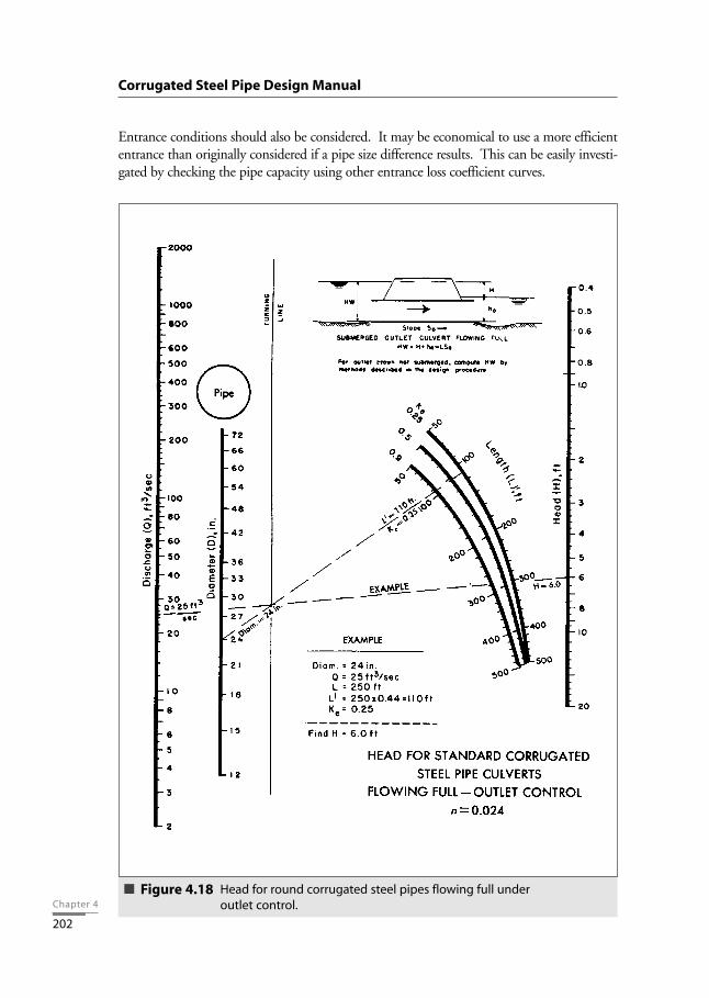
Entrance conditions should also be considered. It may be economical to use a more efficiententrance than originally considered if a pipe size difference results. This can be easily investi-gated by checking the pipe capacity using other entrance loss coefficient curves.
Corrugated Steel Pipe Design Manual
Head for round corrugated steel pipes flowing full underoutlet control.
Figure 4.18

Chapter 4
203
Hydraulic Design • Culverts
Head for round structural plate corrugated steel pipesflowing full under outlet control.
Figure 4.19

Chapter 4
204
Corrugated Steel Pipe Design Manual
Head for corrugated steel pipe arches flowing full underoutlet control.
Structural plate pipe arch for an irrigation ditch crossing.
Figure 4.20

Chapter 4
205
Hydraulic Design • Culverts
Head for structural plate corrugated steel pipe arches with 18-in. cor-ner radius, with submerged outlet and flowing full under outlet con-trol. For 31-in. corner radius structures, use structure sizes on the sizescale with equivalent end areas.
Figure 4.21

Chapter 4
206
Corrugated Steel Pipe Design Manual
Head for structural plate corrugated steel arches, with concrete bottomand 0.3 <= rise/span < 0.4, flowing full under outlet control.
Figure 4.22
Chapter 4
207
Hydraulic Design • Culverts
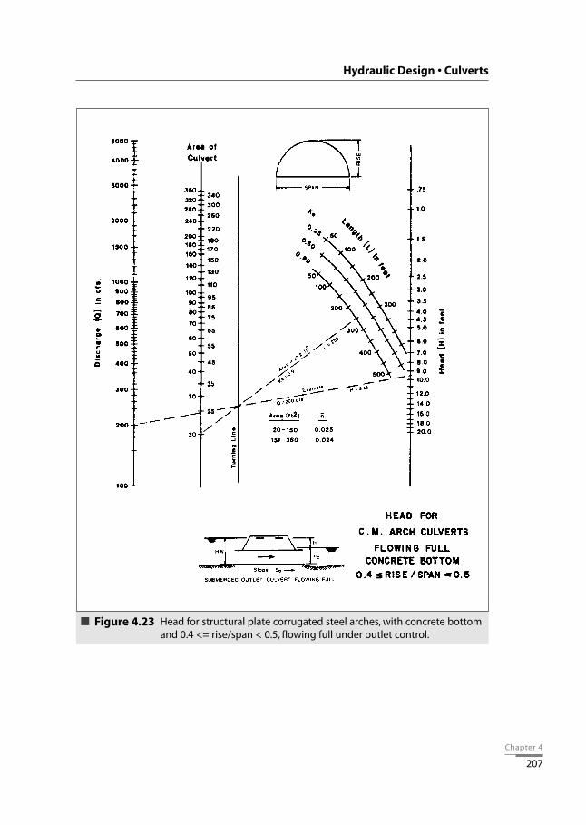
Head for structural plate corrugated steel arches, with concrete bottomand 0.4 <= rise/span < 0.5, flowing full under outlet control.
Figure 4.23

Chapter 4
208
Corrugated Steel Pipe Design Manual
Head for structural plate corrugated steel arches, with concrete bottomand 0.5 <= rise/span, flowing full under outlet control.
Figure 4.24

Chapter 4
209
Hydraulic Design • Culverts
Head for structural plate corrugated steel arches, with earth bottomand 0.3 <= rise/span < 0.4, flowing full under outlet control.
Figure 4.25

Chapter 4
210
Corrugated Steel Pipe Design Manual
Head for structural plate corrugated steel arches, with earth bottomand 0.4 <= rise/span < 0.5, flowing full under outlet control.
Figure 4.26

Chapter 4
211
Hydraulic Design • Culverts
Head for structural plate corrugated steel arches, with earth bottomand 0.5 <= rise/span, flowing full under outlet control.
Figure 4.27

Chapter 4
212
Corrugated Steel Pipe Design Manual
Critical depth for round corrugated steeland structural plate corrugated steel pipes.
Figure 4.28

Chapter 4
213
Hydraulic Design • Culverts
Critical depth for corrugated steel pipe arches.Figure 4.29

Chapter 4
214
Corrugated Steel Pipe Design Manual
Critical depth for structural plate corrugated steel pipe arches.Figure 4.30

Chapter 4
215
Hydraulic Design • Culverts
Critical depth for structural plate corrugated steel arches.Figure 4.31

Chapter 4
216
Improved InletsCulvert capacity may be increased through the use of special inlet designs. The U.S. FederalHighway Administration (FHWA) has developed design methods for these types of structures.While these designs increase the flow, their use has been limited as a result of their cost andthe level of knowledge of designers.
Hydraulic NomographsThe inlet and outlet control design nomographs which appear in this design manual (Figures4.10 through 4.27) were reproduced from nomographs developed and published by theFHWA. A certain degree of error is introduced into the design process due to the fact that theconstruction of nomographs involves graphical fitting techniques resulting in scales which donot exactly match equation results. All of the nomographs used in this design manual have aprecision which is better that ±10 percent of the equation value in terms of headwater depth(inlet control) or head loss (outlet control). This degree of precision is usually acceptable, espe-cially when considering the degree of accuracy of the hydrologic data. If a structure size is notshown on a particular nomograph, accuracy is not drastically affected when a user interpolatesbetween known points.
Partly Full FlowThe pipe capacities derived from the above work are for pipes flowing full. Tables 4.10through 4.14 provide full flow end areas and hydraulic radii for a variety of pipe shapes andsizes. Figures 4.32 through 4.34 provide the means to determine hydraulic section parame-ters for pipes flowing partly full.
The pipe arch shape is used when a low cover situation requires a pipe with less rise or whena larger flow area is desired for a given flow depth. Figure 4.35 shows a comparison, for anequivalent periphery round and pipe arch, of flow areas for a number of flow depths.
Corrugated Steel Pipe Design Manual

Chapter 4
217
Hydraulic Design • Culverts
Table 4.10
Area and hydraulic radius for round pipe flowing full
Diameter Area Hydraulic Diameter Area Hydraulicin. ft2 Radius, ft in. ft2 Radius, ft
1215182124303642485460667278849096
102108114120126132138144150
0.81.21.82.43.14.97.19.6
12.615.919.623.828.133.238.544.250.356.863.670.978.586.695.0
103.9113.1122.7
0.2500.3120.3750.4370.5000.6250.7500.8751.0001.1251.2501.3751.5001.6251.7501.8752.0002.1252.2502.3752.5002.6252.7502.8753.0003.125
156162168174180186192198204210216222228234240246252258264270276282288294300
132.7143.1153.9165.1176.7188.7201.1213.8227.0240.5254.5268.8283.5298.6314.2330.1346.4363.1380.1397.6415.5433.7452.4471.4490.9
3.2503.3753.5003.6253.7503.8754.0004.1254.2504.3754.5004.6254.7504.8755.0005.1255.2505.3755.5005.6255.7505.8756.0006.1256.250
Table 4.11
Area and hydraulic radius for corrugated steel pipe arches flowing full
Diameterin.
151821243036424854606672
Pipe ArchEquivalent
Sizein.
17 x 1321 x 1524 x 1828 x 2035 x 2442 x 2949 x 3357 x 3864 x 4371 x 4777 x 5283 x 57
WaterwayArea
ft2
1.11.62.22.94.56.58.9
11.614.718.121.926.0
HydraulicRadiusA/ππD
ft
0.2800.3400.4000.4620.5730.6900.8100.9241.0401.1531.2681.380
Diameterin.
5460667278849096
102108114120
Pipe ArchEquivalent
Sizein.
60 x 4666 x 5173 x 5581 x 5987 x 6395 x 67
103 x 71112 x 75117 x 79128 x 83137 x 87142 x 91
WaterwayArea
ft2
15.619.323.227.432.137.042.448.054.260.567.474.5
HydraulicRadiusA/ππD
ft
1.1041.2301.3431.4541.5731.6831.8001.9112.0312.1412.2592.373
Corrugations 2 2/3 x 1/2 in. Corrugations 3 x 1 in. and 5 x 1 in.

Chapter 4
218
Corrugated Steel Pipe Design Manual
Table 4.12
Area and hydraulic radius for structural plate pipe arches(6x2 corrugation,3N corner plates with 18 in.radius) flowing full
Dimensions, ft - in.
Waterway Area Hydraulic RadiusSpan Rise ft2 ft
6-1 4-7 22 1.296-4 4-9 24 1.356-9 4-11 26 1.397-0 5-1 28 1.457-3 5-3 30 1.517-8 5-5 33 1.55
7-11 5-7 35 1.61
8-2 5-9 38 1.678-7 5-11 40 1.71
8-10 6-1 43 1.779-4 6-3 45 1.819-6 6-5 48 1.879-9 6-7 51 1.93
10-3 6-9 54 1.9710-8 6-11 57 2.01
10-11 7-1 60 2.0711-5 7-3 63 2.1111-7 7-5 66 2.17
11-10 7-7 70 2.23
12-4 7-9 73 2.2612-6 7-11 77 2.3212-8 8-1 81 2.38
12-10 8-4 85 2.4413-5 8-5 88 2.48
13-11 8-7 91 2.52
14-1 8-9 95 2.5714-3 8-11 100 2.63
14-10 9-1 103 2.6715-4 9-3 107 2.7115-6 9-5 111 2.7715-8 9-7 116 2.83
15-10 9-10 121 2.8916-5 9-11 125 2.9216-7 10-1 130 2.98

Chapter 4
219
Hydraulic Design • Culverts
Table 4.13
Area and hydraulic radius for structural plate pipe arches(6x2 corrugation,5N corner plates with 31 in.radius) flowing full
Span Rise Area Hydraulic Radiusft - in. ft - in. ft2 ft
13-3 9-4 97 2.6813-6 9-6 102 2.7414-0 9-8 105 2.7814-2 9-10 109 2.8314-5 10-0 114 2.90
14-11 10-2 118 2.941 5-4 10-4 123 2.9815-7 10-6 127 3.04
15-10 10-8 132 3.1016-3 10-10 137 3.14
16-6 1 1-0 142 3.201 7-0 1 1-2 146 3.2417-2 1 1-4 151 3.3017-5 1 1-6 157 3.36
17-11 11-8 161 3.40
18-1 11-10 167 3.4518-7 12-0 172 3.5018-9 12-2 177 3.5619-3 12-4 182 3.5919-6 12-6 188 3.65
19-8 12-8 194 3.7119-11 12-10 200 3.7720-5 13-0 205 3.8120-7 13-2 211 3.87
Table 4.14
Area and hydraulic radius for structural plate arches flowing full
Dimensions1
Waterway Area Wetted Perimeter Hydraulic RadiusSpan, ft Rise, ft ft2 ft ft
6.0 1-9-1/2 8 13.2 0.6062-3-1/2 10 14.0 0.714
3-2 15 15.6 0.962
7.0 2-4 12 15.8 0.7592-10 15 16.6 0.9043-8 20 18.2 1.099
8.0 2-11 17 18.4 0.9243-4 20 19.2 1.0424-2 26 20.8 1.250
9.0 2-11 19 20.2 0.9413-10-1/2 27 21.8 1.2394-8-1/2 34 23.4 1.453

Chapter 4
220
Corrugated Steel Pipe Design Manual
Table 4.14 continued
Area and hydraulic radius for structural plate arches flowing full
Dimensions1
Waterway Area Wetted Perimeter Hydraulic RadiusSpan, ft Rise, ft ft2 ft ft
10.0 3-5-1/2 26 22.8 1.1404-5 34 24.4 1.3935-3 41 26.0 1.577
11.0 3-6 28 24.6 1.1384-5-1/2 37 26.2 1.412
5-9 50 28.6 1.748
12.0 4-0-1/2 35 27.2 1.2875-0 45 28.8 1.5636-3 59 31.2 1.891
13.0 4-1 38 29.0 1.3105-1 49 30.6 1.6016-9 70 33.8 2.071
14.0 4-7-1/2 47 31.6 1.4875-7 58 33.2 1.7477-3 80 36.4 2.198
15.0 4-7-1/2 50 33.4 1.4975-8 62 35.0 1.7716-7 75 36.6 2.0497-9 92 39.0 2.359
16.0 5-2 60 36.0 1.6677-1 86 39.2 2.1948-3 1 05 41.6 2.524
17.0 5-2-1/2 63 37.8 1.6677-2 92 41.0 2.244
8-10 119 44.2 2.692
18.0 5-9 74 40.4 1.8327-8 104 43.6 2.385
8-11 125 46.8 2.671
19.0 6-4 87 43.0 2.0238-2 118 46.2 2.554
9-5-1/2 140 49.4 2.834
20.0 6-4 91 45.6 1.9968-3-1/2 124 48.0 2.521
10-0 157 51.2 3.066
21.0 6-11 104 47.4 2.1948-10 140 50.6 2.76710-6 172 53.8 3.197
22.0 7-11 128 48.7 2.6288-11 1 46 52.4 2.78611-0 190 56.4 3.369
23.0 8-0 134 52.6 2.5489-10 170 55.8 3.04711 -6 207 59.0 3.508
24.0 8-6 149 55.2 2.69910-4 188 58.4 3.21912-0 226 61.6 3.669
25.0 8-6-1/2 155 57.0 2.71910-10-1/2 207 61.0 3.393
12-6 245 64.2 3.816
1 Dimensions are to inside crests and are subject to manufacturing tolerances.

Chapter 4
221
Hydraulic Design • Culverts
Hydraulic section parameters for circular corrugated steeland structural plate pipes.
Figure 4.32
Hydraulic section parameters for corrugated steeland structural plate pipe arches.
Figure 4.33

Chapter 4
222
Corrugated Steel Pipe Design Manual
Hydraulic section parameters for structural plate arches.Figure 4.34
Comparison of waterway cross-sectional areas,at a constant depth of flow, in pipe and pipe arch shapes.
Figure 4.35

Chapter 4
223
Hydraulic ProgramsNumerous computer programs now exist to aid in the design and analysis of highway cul-verts. These programs possess distinct advantages over traditional hand calculation meth-ods. The increased accuracy of programmed solutions represents a major benefit over theinaccuracies inherent in the construction and use of tables and nomographs. In addition,programmed solutions are less time consuming. This feature allows the designer to com-pare alternative sizes and inlet configurations very rapidly so that the final culvert selec-tion can be based on economics. Interactive capabilities in some programs can be utilizedto change certain input parameters or constraints and analyze their effects on the finaldesign. Familiarity with culvert hydraulics and the traditional analytical methods pro-vides a solid basis for designers to take advantage of the speed, accuracy and increasedcapabilities available in culvert hydraulics programs.
Most programs analyze the performance of a given culvert, although some are capable ofdesign. Generally, the desired result of either type of program is to obtain a culvert designwhich satisfies hydrologic needs and site conditions by considering both inlet and outletcontrol. Results usually include the barrel size, inlet dimensions, headwater depth, out-let velocity and other hydraulic data. Some programs are capable of analyzing side-tapered and slope-tapered inlets. The analysis or design of the barrel size can be for onebarrel only or for multiple barrels.
Some programs may contain features such as backwater calculations, performance curves,hydrologic routines and capabilities for routing based on upstream storage considerations.
HYDRAULICS OF LONG SPAN STRUCTURES
IntroductionStandard procedures are presented here to determine the headwater depth resulting froma given flow through a long span structure under both inlet and outlet control conditions.The most common long span hydraulic shapes are the horizontal ellipse, the low profilearch and the high profile arch. Useful hydraulic data pertaining to these shapes are pre-sented in tabular and graphic form. Basic hydraulic equations, flow conditions and def-initions have been given previously. However, long span hydraulics include factors whichare not considered in the earlier calculations.
DesignLong span structures are often small bridges that span the flood channel. This type ofstructure ordinarily permits little or no ponding at the inlet. Maximum headwater is usu-ally below the top of the structure. In other words, there is usually some freeboard
Hydraulic Design • Culverts

Chapter 4
224
between the water surface and the top of the structure. This condition is quite differentfrom the ordinary culvert, which normally presents a small opening in an embankmentcrossing a larger flood channel.
The typical long span hydraulic conditions just described maintain effective approachvelocity. The following long span hydraulic design procedure considers this approachvelocity. The formulas and coefficients taken from the U.S. Federal HighwayAdministration (FHWA) methodology have been modified to include the approachvelocity. In this discussion, headwater, HW, refers to the water surface and not to theenergy grade line. This is different from the FHWA procedures, where HW refers to theenergy grade line, which corresponds to HW + Φ in this discussion.
Design ChartInlet control is expected to govern in most long spans. Figure 4.36 allows the designer toconveniently calculate the headwater depth for three standard shapes having the mosttypical inlet condition. This figure is a plot of the two design equations below (for unsub-merged and submerged inlets), and is based on an inlet that is either a square end with aheadwall or a step-beveled end with a concrete collar (Type 1 in Table 4.15). The accu-racy of the curves is within the degree to which the graph can be read. Using the designdischarge and the structure span and rise, the curve for the structure desired gives theratio of the headwater depth, approach velocity head and slope correction to the struc-ture rise. The headwater depth is determined by subtracting the velocity head and slopecorrection from the product of the ratio and the structure rise. Figure 4.36 also includesa table of velocity heads for a variety of approach velocities.
Corrugated Steel Pipe Design Manual
Table 4.15
Entrance loss coefficients for long spans
Type Unsubmerged SubmergedInlet kd kp k j ke Maximum Mnimum
1 0.0379 0.69 0.0083 2.0 0.5 3.3 3.82 0.0300 0.74 0.0018 2.5 0.2 3.3 4.2
1) Type 1 inlet is square end with headwall or step-beveled end with concrete collar.
2) Type 2 inlet is square or step-beveled end with mitered edge on headwall. Step-beveled inlets were notincluded in FHWA criteria.
3) Special improved inlet configurations can reduce headwater depths.
4) Coefficient k and kd are not dimensionless.
Entrance CoefficientsQ
AD 1/2

Chapter 4
225
Hydraulic Design • Culverts
Headwater depth for long span corrugated steel structuresunder inlet control.
Figure 4.36

Chapter 4
226
Design Calculations
Inlet ControlThe equations for calculating headwater depth for long span structures under inlet controlare as follows:
For unsubmerged inlets:
For submerged inlets:
where: HW = headwater depth from the invert to the water surface, ftHc = critical head, ftHe = increment of head above the critical head, ftSo = slope of the structure, ft/ftD = rise of the structure, ftV1 = approach velocity, ft/sg = gravitational constant, 32.2 ft/s2
kd, kp = coefficients based on inlet type (Table 4.15)Q = design discharge, ft3/sA = full cross-sectional end area of the structure, ft2
To determine if the flow condition is submerged or unsubmerged, the value of is calculated and reference is made to Table 4.15. If the flow is in the transitionzone between unsubmerged and submerged, a reasonable approximation can be made byusing both equations and interpolating based on where the value occurs relative to the lim-its in the table. When a performance curve is plotted, such as in Figure 4.36, the transitionzone is filled in manually.
The critical head is equal to the critical depth in the structure at design flow plus the veloc-ity head at that flow:
where: dc = critical depth, ftVc= critical velocity, ft/s
Vc2
Hc = dc + 2g
Q
AD1/2 1{ }
Q 2 V12
HW = kd D + kp D - 0.5 So D -AD1/2 2g{ }
V12
HW = Hc + He - 0.5 So D -2g
Corrugated Steel Pipe Design Manual

Chapter 4
227
The critical depth can be interpolated from Tables 4.16 through 4.18. Using the designdischarge, the critical depth (as a decimal fraction of the structure rise) is estimated byinterpolating between known discharges for a number of set critical depth decimal frac-tions.
Hydraulic Design • Culverts
Table 4.16
Hydraulic section parameters for long span structural plate horizontal ellipses
19-4 x 12-920-1 x 13-020-2 x11-1120-10 x 12-2
21-0 x 15-221-11 x 13-122-6 x 15-823-0 x 14-1
23-3 x 15-1124-4 x 16-1124-6 x 14-8
25-2 x 14-11
25-5 x 16-926-1 x 18-2
26-3 x 15-1027-0 x 16-2
27-2 x 19-127-11 x 19.528-1 x 17-1
28-10 x 17-5
29-5 x 19-1130-1 x 20-230.3 x 17-1131-2 x 21-2
31-4 x 18-1132-1 x 19-232-3 x 22-233-0 x 22-5
33-2 x 20-134-1 x 23-434-7 x 20-8
34-11 x 21-4
35-1 x 24-436-0 x 22-437-2 x 22-2
191202183194
248221274249
288320274287
330369320334
405421369384
455472415513
454471555574
512619548574
665619631
50.752.350.752.3
57.155.560.358.7
61.965.161.963.5
66.769.966.968.3
73.174.771.573.1
77.979.576.382.7
79.581.185.987.5
84.390.787.589.1
93.992.393.9
3.773.863.613.71
4.353.984.554.25
4.654.924.434.53
4.955.284.804.89
5.545.645.165.26
5.845.945.446.20
5.715.816.466.56
6.086.826.266.44
7.086.716.72
462.7497.1430.6464.9
660.9555.0752.4653.3
802.3925.7739.1785.7
958.51118.9910.6962.2
1268.01334.01101.91161.4
1475.51548.11283.61731.3
1450.41522.21925.12011.5
1705.62226.11861.41986.9
2452.02202.12247.0
769823708756
1073897
12281051
1298148611771242
1523177514301503
1999209517141795
2289239119682659
2212230929473064
2577337627922975
370532863328
1204128211101154
1684140319211645
2033232718431947
2383277822402356
3131327826832812
3587374430844166
3467361746154798
4038528643724661
580151465215
1714183215841694
2390200527322347
2889330726342782
3391394931963366
4448466038304016
5098532644065925
4950517365616825
5762749562456652
824673417450
2316247821532298
3225272536873185
3903446435773780
4588533143404572
6004629051925452
6887719859858003
6720702088709220
78191015084819070
111319950
10100
3083329828713088
4336364048864256
5179591447855060
6101704658046113
7953832969437288
914395638014
10622
89839389
1175212236
10451134641132012053
147541328313537
4183450239354194
5901496659795801
7046805565186881
8295961179028303
108171132594389919
12434130081090014429
12205127741596416639
14210182801542416397
200481805418381
Span x Rise(B x D)ft - in.
Areaft2
WPft
Rft AR 2/3 0.40 0.50 0.60 0.70 0.80 0.90
Critical Depth Factor*
Discharge - (Q), ft2/secFull Flow Data
* Multiply factor by structure rise.

Chapter 4
228
Corrugated Steel Pipe Design Manual
Table 4.17
Hydraulic section parameters for long span structural plate low profile arches
20-1 x 7-619-5 x 6-921-6 x 7-9
22-3 x 7-11
23-0 x 8-023-9 x 8-224-6 x 8-325-2 x 8-5
25-11 x 8-727-3 x 10-028-1 x 9-6
28-9 x 10⁻³
28-10 x 9-830-3 x 9-11
30-11 x 10-831-7 x 12-1
31-0 x 10-132-4 x 12-331-9 x 10-233-1 x 12-5
33-2 x 11-134-5 x 13-334-7 x 11-4
37-11 x 15-7
35-4 x 11-538-8 x 15-9
120105133140
147154161168
176217212234
220237261309
246319255330
289367308477
318490
47.945.651.052.5
54.155.657.258.7
60.264.865.667.9
67.170.272.576.1
71.777.673.379.1
77.183.080.292.9
81.794.4
2.512.302.622.67
2.722.772.822.86
2.913.343.233.44
3.283.383.594.06
3.434.113.474.17
3.744.423.845.13
7871469
223183253269
286304321339
359485463533
486534612786
560819585855
696988755
1419
19623466
579480656698
738784830876
923122811791343
1236135315361901
1416197914802085
1741237218863356
27844881
819681929986
1042111211801249
1320173316661896
1747191421682684
2004279520992907
2459334626744726
37306496
1119933
12661344
1420150815931682
1774234022522558
2361258629223607
2702376028243916
3313446735896290
47828426
1443120616321720
1829194420542166
2290301729013297
3040332637614676
3476486936315065
4264581546148158
608910727
1839153220812207
2324246626122756
2901383636854193
3863422047605961
4411620146116443
541374005853
10390
801514122
2448204927232926
3083326734223640
3848504648585538
5105554362927836
5806814260868500
709997307722
13646
Span x Rise(B x D)ft - in.
Areaft2
WPft
Rft AR 2/3 0.4D 0.5D 0.6D 0.7D 0.8D 0.9D
Critical Depth Factor*
Discharge - (Q), ft3/secFull Flow Data
* Multiply factor by structure rise.
Housing Development in Thornton, Colorado. Super Cor Box Culvert 35’-9”span x 7’-9”rise.

Chapter 4
229
Hydraulic Design • Culverts
Table 4.18
Hydraulic section parameters for long span structural plate high profile arches
20-1 x 9-1 152 50.8 2.99 315.5 785 1107 1480 1923 2466 328220-8 x 12-1 214 56.5 3.78 518.6 1191 1687 2264 2936 3790 504421-6 x 11-8 215 57.5 3.73 516.1 1179 1669 2234 2911 3765 4989
22-10 x 14-6 284 63.9 4.45 768.9 1690 2402 3227 4193 5412 7209
22-3 x 11-10 224 59.1 3.80 546.5 1246 1762 2361 3077 3974 529722-11 x 14-0 275 63.3 4.34 731.3 1601 2279 3050 3969 5140 685323-0 x 11-11 234 60.7 3.86 576.7 1315 1858 2491 3246 4191 558924-4 x 14-10 309 67.2 4.60 854.4 1874 2658 3569 4636 5989 7980
23-9 x 12-1 244 62.3 3.93 608.8 1385 1956 2623 3418 4417 586924.6 x 13-9 288 66.0 4.37 770.5 1680 2376 3187 4154 5391 720025-9 x 15-1 334 70.5 4.74 942.5 2063 2924 3923 5096 6586 876925-2 x 13-1 283 66.6 4.25 742.0 1650 2331 3125 4079 5280 7030
26-6 x 15-3 347 72.1 4.81 988.1 2161 3062 4106 5312 6896 918425-11 x 13-3 294 68.2 4.31 778.4 1730 2445 3276 4280 5534 734827-3 x 15-5 360 73.7 4.88 1034.6 2260 3201 4292 5577 7803 958427-5 x 13-6 317 71.3 4.44 855.0 1896 2679 3591 4692 6064 8068
29-5 x 16-5 412 79.2 5.20 1235.4 2697 3820 5118 6639 8570 1139028-2 x 14-5 348 74.0 4.70 976.0 2123 2998 4019 5255 6802 905030-1 x 18-0 466 82.8 5.63 1474.0 3111 4402 5920 7694 9952 1326630-3 x 15-5 399 79.5 5.02 1169.0 2539 3589 4811 6278 8114 10775
31-7 x 18-4 496 86.1 5.77 1596.6 3366 4768 6405 8315 10760 1429131-0 x 15-7 412 81.1 5.08 1216.8 2642 3734 5004 6534 8437 1117331-8 x 17-9 483 85.4 5.65 1531.5 3222 4556 6114 7960 10323 13760
32-4 x 19-11 553 90.0 6.18 1863.2 3808 5404 7259 9450 12256 16350
31-9 x 17-2 469 84.8 5.53 1466.4 3080 4353 5836 7615 9890 1319033-1 x 20-1 570 91.2 6.25 1934.9 3940 5610 7534 9807 12721 1696332-6 x 17-4 484 86.4 5.60 1524.8 3200 4522 6061 7917 10270 13675
33-10 x 20-3 587 92.9 6.33 2009.9 4106 5820 7814 10172 13197 17607
34-0 x 17-8 513 89.6 5.73 1643.2 3445 4867 6524 8532 11054 1470334-7 x 19-10 590 93.9 6.28 2007.6 4095 5797 7775 10136 13176 1757534-8 x 17-9 528 91.2 5.79 1703.0 3572 5043 6762 8844 11458 1521035-4 x 20-0 607 95.5 6.35 2080.4 4255 6022 8076 10534 13697 18270
Span x Rise(B x D)ft - in.
Areaft2
WPft
Rft AR 2/3 0.4D 0.5D 0.6D 0.7D 0.8D 0.9D
Critical Depth Factor*
Discharge - (Q), ft3/secFull Flow Data
* Multiply factor by structure rise.
Chapter 4
230
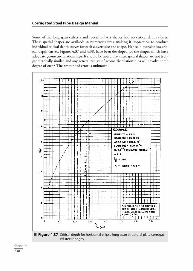
Some of the long span culverts and special culvert shapes had no critical depth charts.These special shapes are available in numerous sizes, making it impractical to produceindividual critical depth curves for each culvert size and shape. Hence, dimensionless crit-ical depth curves, Figures 4.37 and 4.38, have been developed for the shapes which haveadequate geometric relationships. It should be noted that these special shapes are not trulygeometrically similar, and any generalized set of geometric relationships will involve somedegree of error. The amount of error is unknown.
Corrugated Steel Pipe Design Manual
Critical depth for horizontal ellipse long span structural plate corrugat-ed steel bridges.
Figure 4.37
Chapter 4
231
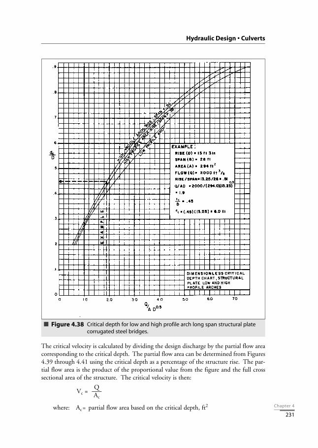
The critical velocity is calculated by dividing the design discharge by the partial flow areacorresponding to the critical depth. The partial flow area can be determined from Figures4.39 through 4.41 using the critical depth as a percentage of the structure rise. The par-tial flow area is the product of the proportional value from the figure and the full crosssectional area of the structure. The critical velocity is then:
where: Ac= partial flow area based on the critical depth, ft2
QVc =
Ac
Hydraulic Design • Culverts
Critical depth for low and high profile arch long span structural platecorrugated steel bridges.
Figure 4.38

Chapter 4
232
Corrugated Steel Pipe Design Manual
Hydraulic section parameters for long span horizontal ellipses.Figure 4.39
Hydraulic section parameters for long span low profile arches.Figure 4.40

Chapter 4
233
The accuracy of the critical depth may be checked using the basic equation for criticalflow:
where: Tc= width of the water surface for the critical depth case, ft
For this calculation, detailed structure cross section geometry is required in order to cal-culate the water surface width when the water depth is the critical depth.
The increment of head above the critical head is:
where: k, j = coefficients based on inlet type (Table 4.15)
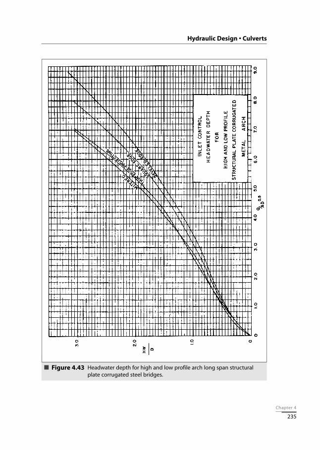
By plotting the results of the unsubmerged and submerged calculations and connecting theresultant curves with transition lines, the dimensionless design curves shown in Figures4.42 and 4.43 were developed. All circular and elliptical shapes can be represented by asingle curve for each inlet edge configuration. A similar set of curves was developed forhigh and low profile arches. It is recommended that the curves shown in Figure 4.42 be
QAD1/2
j{ }He = k D
gAc3
Tc
Qc =
Hydraulic Design • Culverts
Hydraulic section parameters for long span high profile arches.Figure 4.41

Chapter 4
234
used for curved shapes including circles, ellipses and pear shapes, and that the high andlow profile arch curves in Figure 4.43 be used for all true arch shapes (those with a flatbottom).
Corrugated Steel Pipe Design Manual
Headwater depth for circular and elliptical long span structural platecorrugated steel bridges.
Figure 4.42
Chapter 4
235
Hydraulic Design • Culverts
Headwater depth for high and low profile arch long span structuralplate corrugated steel bridges.
Figure 4.43

Chapter 4
236
Outlet Control
Free Water Surface
The situation where a long span has a free water surface extending through its full or near-ly full length, as shown in Figure 4.5 D (possibly the most common flow condition),exists when the headwater depth is less than:
where: ke = entrance loss coefficient based on inlet type (Table 4.15)
Under this condition, the headwater depth must be determined by a backwater analysisif accurate results are required. Datum points d1 and d2 are established upstream anddownstream from the structure, beyond the influence of the entrance and outlet. Thebackwater analysis determines the water surface profile by starting at the downstreampoint and moving to the upstream point. The backwater analysis must consider channelgeometry between the downstream point and the outlet end of the structure, outlet loss,changing geometry of flow within the structure, inlet loss, and conditions between theinlet end of the structure and the upstream point.
As discussed previously, long span hydraulic properties are provided in Tables 4.16through 4.18 and Figures 4.39 through 4.41, and entrance loss coefficients are in Table4.15. The exit loss for these types of structures is typically very small and is often assumedto be zero.
Backwater analyses are considered outside the scope of this design manual. There are ref-erences that provide guidance for this procedure. In particular, the FHWA’s "HydraulicDesign of Highway Culverts" CDROM contains a discussion and example of the back-water analysis procedure.
Full Flow
When full flow or nearly full flow exists, the headwater depth is determined by the fol-lowing:
where: HW = headwater depth, ftke = entrance loss coefficient (Table 4.15)g = gravitational constant = 32.2 ft/s2
n = Manning’s friction factor (Table 4.7)L = length of long span, ftR = hydraulic radius, ft = A / WP
HW = (ke + + 1) + ho – L So – V12
2g2gn2 LR4/3
V2
2g
Vc2
2gD + (1 + ke)
Corrugated Steel Pipe Design Manual

A = full cross sectional area of the long span, ft2
WP = perimeter of the long span, ftV = velocity, ft/sho = outlet datum, ftSo = slope of structure, ft/ftV1 = approach velocity, ft/s
These conditions are as shown in Figure 4.5 A through C. They occur when the head-water depth is greater than:
For arches or lined structures, a composite Manning’s n value must be developed. Amethod described in an FHWA document is based on the assumption that the con-veyance section can be broken down into a number of parts with associated wettedperimeters and Manning’s n values. Each part of the conveyance section is then assumedto have a mean velocity equal to the mean velocity of the entire flow section. Theseassumptions lead to:
where: n = weighted Manning’s n valueG = number of different roughnesses in the perimeterpi = wetted perimeter influenced by material i, ftni = Manning’s n value for material ip = total wetted perimeter, ft
In the case of arches, the wetted perimeter used in hydraulic radius calculations includesthat portion of the structure above the natural channel and the natural channel itself.
For flow conditions as shown in Figure 4.5 A and B, when the tailwater depth is equal toor greater than the structure rise:
ho = TW
For flow conditions as shown in Figure 4.5 C, when the tailwater depth is less than thestructure rise:
ho = or TW (whichever is greater)dc+ D2
Σ (pini1.5)
pi=1
0.67G[ ]n =
Vc2
2gD + (1 + ke)
Chapter 4
237
Hydraulic Design • Culverts

Chapter 4
238
The velocity, V, is determined by dividing the design discharge by the area, where the areais the full cross sectional area of the long span structure.
The remaining terms in the equation can be determined as previously discussed.
Summary of Procedure
Step 1. Collect all available information for the design. This includes the requireddesign discharge, the structure length and slope, an allowable headwater eleva-tion or depth, the average and maximum flood velocities in the channel, theproposed entrance type and a desired structure shape.
Step 2. Select an initial structure size. This may be an arbitrary choice or estimatedusing a maximum allowable velocity. To estimate a structure size, the minimumstructure end area is determined by dividing the design discharge by the maxi-mum allowable velocity. Geometric constraints may also influence the choiceof an initial structure size. An example of this is where a minimum structurespan is required to bridge a channel.
Step 3. Use Figure 4.36 and the design parameters to obtain a value for HW + Φ andthen the headwater depth, HW. When required, more accurate results can beachieved by using the inlet control formulas to calculate the headwater depth.
Step 4. Check the calculated headwater depth against the allowable headwater depth.If the calculated headwater depth is greater than the allowable, select a largerstructure and repeat Step 3. If the calculated headwater depth is less than theallowable, this is the resulting headwater depth for the structure selected underinlet control.
Step 5. Calculate
If this value is greater than the allowable headwater depth, use the backwatercurve method to determine the water surface profile through the structure andthe headwater depth. If this value is equal to or less than the allowable head-water depth, the full flow formula should be used to determine the headwaterdepth. The resulting headwater depth is for the structure selected under outletcontrol.
Step 6. Compare the inlet and outlet control headwater depths and use the larger. If theresulting headwater depth is greater than the allowable, a larger size or differentshape structure should be chosen and the procedure repeated. If the headwaterdepth is significantly less than the allowable, a smaller size can be chosen and theprocedure repeated in order to economize on the structure size.
Vc2
2gD + (1 + ke)
Corrugated Steel Pipe Design Manual

Chapter 4
239
HYDRAULICS OF STEEL BOX CULVERTS
Where large waterway openings are required with no or minimal ponding, a box culvertis often used. With a HW ratio of less than one (1.0), the steel structural plate box cul-vert may be designed as an open channel. This is the most efficient hydraulic design forthis condition.
By examining the geometry, it can be seen that the nearly vertical legs and flat bottomwill provide a linear relationship with lower depths of flow (to 0.6D, where D is the boxculvert rise). As the water surface elevation increases and begins to contact the corner orhaunch sections, the wetted perimeter increases at a rate faster than the rate of increase inthe waterway area. At water depths of 0.8D to 1.0D, there is a rapid increase in wettedperimeter and very little increase in area. Therefore, it can be seen that maximum flowwill occur at a point somewhat less than full (0.8 to 0.9D).
Manning’s equation is the accepted design method for open channel flow. Table 4.19 andFigures 4.44 through 4.57 provide hydraulic design information for steel box culvertswith a 6 x 2 inch corrugation. The procedure is similar to that summarized previously.
Hydraulic Design • Culverts
Table 4.19
Hydraulic section parameters for structural plate box culverts
No.Spanft-in.
Riseft-in.
Area(sq ft)
WPft.
AR 2/3 AD 1/2 No.Spanft-in.
Riseft-in.
Area(sq ft)
WPft.
AR 2/3 AD 1/2
123456789
101112131415161718192021222324252627
9-29-8
10-611-1
11-1012-913-214-114-69-0
10-110-1015-411-616-012-216-8
12-1013-617-614-418-29-6
14-1010-715-718-9
2-62-72-82-9
2-102-113-13-23-33-43-43-53-53-63-63-83-83-9
3-103-104-04-04-14-14-24-24-2
18.420.222.624.827.830.633.536.639.024.227.730.843.333.246.237.250.739.744.054.047.858.831.151.335.955.662.2
20.022.223.824.326.728.329.631.331.721.423.525.734.126.635.528.637.329.431.038.033.240.023.634.226.236.140.7
17.419.021.825.128.532.236.340.644.826.330.934.850.838.555.044.362.248.555.668.261.076.037.467.244.374.182.6
29.132.536.941.146.852.358.865.170.344.250.656.980.062.186.471.297.176.986.1
105.795.6
117.662.8
103.773.3
113.5127.0
282930313233343536373839404142434445464748495051525354
11-219-511-916-312-613-3
16-1020-017-920-813-914-718-410-011-015-019-221-611-8
15-1012-519-8
12-1016-417-220-813-8
4-34-34-44-44-54-64-64-64-74-74-84-94-9
4-114-114-114-114-115-05-05-15-15-25-25-35-35-4
39.466.042.459.546.949.464.170.867.274.754.859.173.139.144.263.278.283.848.268.152.582.356.672.277.688.460.8
27.742.628.337.030.731.538.843.240.045.033.035.042.025.728.235.743.247.329.037.831.344.532.038.840.646.534.0
49.888.455.681.762.366.789.598.595.0
104.776.883.9
105.851.759.792.5
116.1122.667.6
100.874.2
124.082.8
109.2119.5135.689.6
81.2136.188.3
123.998.6
104.8136.0150.2143.9159.9118.4128.8159.386.798.0
140.1173.4185.8107.8152.3118.4185.6128.7164.1177.8202.5140.4
(continued)

Chapter 4
240
Corrugated Steel Pipe Design Manual
Table 4.19 (continued)
Hydraulic section parameters for structural plate box culverts
No.Spanft-in.
Riseft-in.
Area(sq ft)
WPft.
AR 2/3 AD 1/2 No.Spanft-in.
Riseft-in.
Area(sq ft)
WPft.
AR 2/3 AD 1/2
555657585960616263646566676869707172737475767778798081828384858687888990919293949596979899
100101102103104105106107108
22-814-018-021-211-0
14-1018-411-515-519-322-212-016-0
19-1023-9
12-1016-813-214-017-219-223-420.1124-1014-418-0
10-1015-118-411-915-619-220-222-524-412-516-313-119-813-6
16-1017-521-314-219-723-514-818-121-225-415-511-418-912-3
5-45-55-55-55-75-75-75-85-85-85-85-9
5-105-105-105-115-116-06-16-16-16-16-26-26-36-36-46-46-46-56-66-66-66-66-66-76-76-86-86-96-9
6-106-106-116-116-117-07-07-07-07-17-27-27-3
95.065.682.294.147.970.787.952.675.193.3
101.057.280.797.2
108.262.384.766.672.191.397.1
113.7105.5119.076.696.953.882.5
101.961.287.1
106.6109.2118.4127.266.493.572.3
113.376.998.3
105.1121.783.1
111.9132.188.4
111.1127.4142.294.563.0
117.371.2
49.764.742.247.529.036.843.529.737.645.149.331.139.846.352.833.140.733.835.942.544.751.948.254.336.743.829.638.744.931.739.246.647.551.055.133.041.635.147.635.842.244.350.331.846.853.738.845.250.857.640.631.846.534.4
146.2100.3128.3148.466.9
109.2140.577.0
119.2151.5163.085.9
129.4159.4174.694.9
138.0104.7114.8152.1162.8191.7177.9200.7125.2164.480.2
136.6176.094.9
148.2185.2190.3207.5222.3105.8160.5117.1202.0128.1172.8186.8219.4140.6200.0240.7153.1202.5235.3259.8166.199.3
217.2115.6
219.4152.7191.3219.0113.2167.1207.7125.2178.8222.1240.4137.2194.9234.8261.3151.5206.0163.1177.8225.2239.5280.4262.0295.5191.5242.3135.4207.6256.4155.0222.1271.8278.4301.9324.3170.4239.9186.7292.5199.8255.4274.7318.1218.5294.3347.4233.9293.9337.1376.2251.5168.7314.0191.7
109110111112113114115116117118119120121121123124125126127128129130131132133134135136137138139140141142143144145146147148149150151152153154155156157158159160161
15-820-722-7
12-1019-124-513-416-6
16-1019-1014-014-417-620-021-223-615-025-418-315-8
18-1020-1016-019-3
20-1122-1016-824-6
16-1020-217-120-4
21-1017-823-818-421-225-4
18-1121-323-019-424-620-0
21-1023-1021-325-423-224-824-025-524-9
7-37-37-37-47-47-47-57-57-67-67-77-87-87-87-87-87-97-9
7-107-117-117-118-18-18-18-18-28-28-38-38-38-58-58-68-68-78-78-78-9
8-108-108-118-119-19-39-39-59-59-89-9
10-110-210-6
98.7125.0135.976.0
121.5146.880.4
106.5111.5129.888.491.0
119.0127.1134.8150.699.4
161.3125.5106.8132.1143.3111.8135.9141.2153.7119.6166.2124.4146.2125.8142.6155.7133.0169.3139.9160.7182.4147.0157.6171.6152.1185.7161.6173.3188.1177.4202.9189.8205.3207.0222.7225.0
41.149.452.935.047.656.536.143.344.149.538.438.645.648.750.955.640.659.147.242.548.751.743.249.251.354.744.858.145.651.545.750.753.947.557.248.754.160.850.053.456.451.259.953.055.959.255.662.258.461.560.994.063.2
176.9232.1255.0127.4226.8277.6137.2194.1207.0246.7154.0161.3225.6240.9258.1292.7180.6315.1240.9197.3256.8282.6210.9267.4277.2306.1230.2334.9243.0293.2246.9284.0315.9264.2349.0282.5332.0379.4301.7324.2360.1314.3394.8339.9368.4406.8384.4446.1416.4458.7468.0511.4524.6
265.8336.6365.9205.8329.0397.5219.0290.0305.4355.5243.4252.0329.5351.9373.2417.0276.7449.0351.2300.5371.7403.2317.9386.4401.4437.0341.8475.0357.3419.9363.2413.7451.7387.8493.6409.9470.8534.4434.8468.4510.0454.2554.5487.0527.1572.1544.4622.6590.1641.0657.3710.1729.1

Chapter 4
241
Hydraulic Design • Culverts
Headwater depths for structural plate box culverts,with rise/span < 0.3, under inlet control.
Figure 4.44

Chapter 4
242
Corrugated Steel Pipe Design Manual
Headwater depths for structural plate box culverts,with 0.3 <= rise/span < 0.4, under inlet control.
Figure 4.45

Chapter 4
243
Hydraulic Design • Culverts
Headwater depths for structural plate box culverts,with 0.4 <= rise/span < 0.5, under inlet control.
Figure 4.46

Chapter 4
244
Corrugated Steel Pipe Design Manual
Headwater depths for structural plate box culverts,with 0.5 <= rise/span, under inlet control.
Figure 4.47
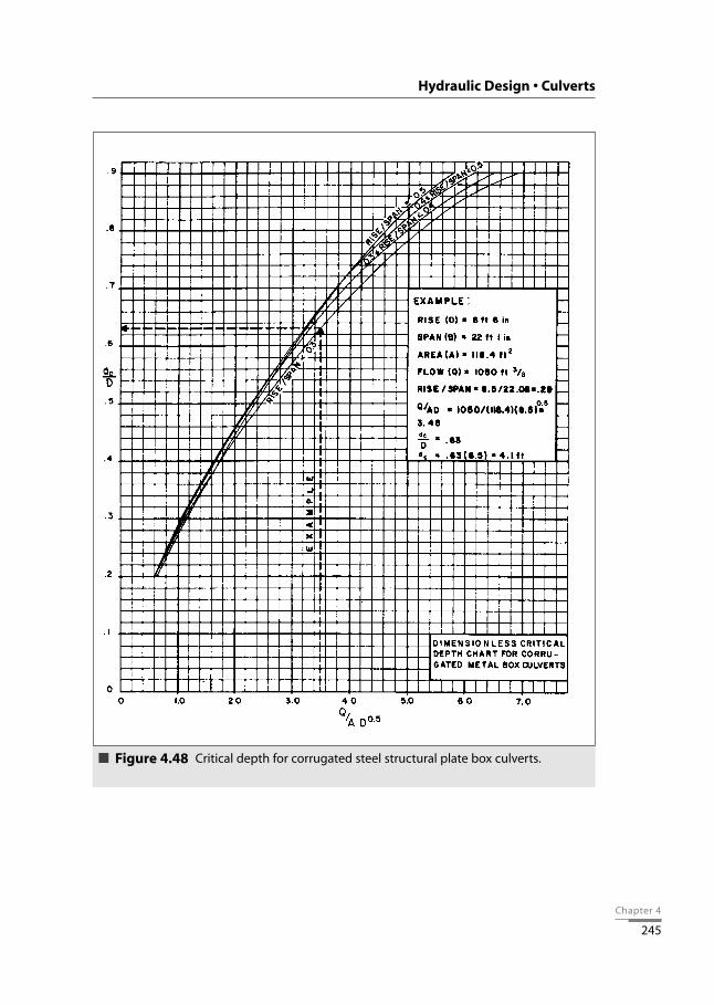
Chapter 4
245
Hydraulic Design • Culverts
Critical depth for corrugated steel structural plate box culverts.Figure 4.48

Chapter 4
246
Corrugated Steel Pipe Design Manual
Head for 6x2 structural plate box culverts, with concrete invert andrise/span < 0.3, flowing full under outlet control.
Figure 4.49

Chapter 4
247
Hydraulic Design • Culverts
Head for 6x2 structural plate box culverts, with concrete invert and0.3 <= rise/span < 0.4, flowing full under outlet control.
Figure 4.50

Chapter 4
248
Corrugated Steel Pipe Design Manual
Head for 6x2 structural plate box culverts, with concrete invert and0.4 <= rise/span < 0.5, flowing full under outlet control.
Figure 4.51
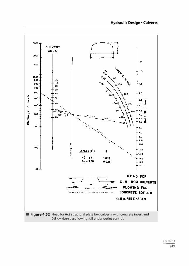
Chapter 4
249
Hydraulic Design • Culverts
Head for 6x2 structural plate box culverts, with concrete invert and 0.5 <= rise/span, flowing full under outlet control.
Figure 4.52
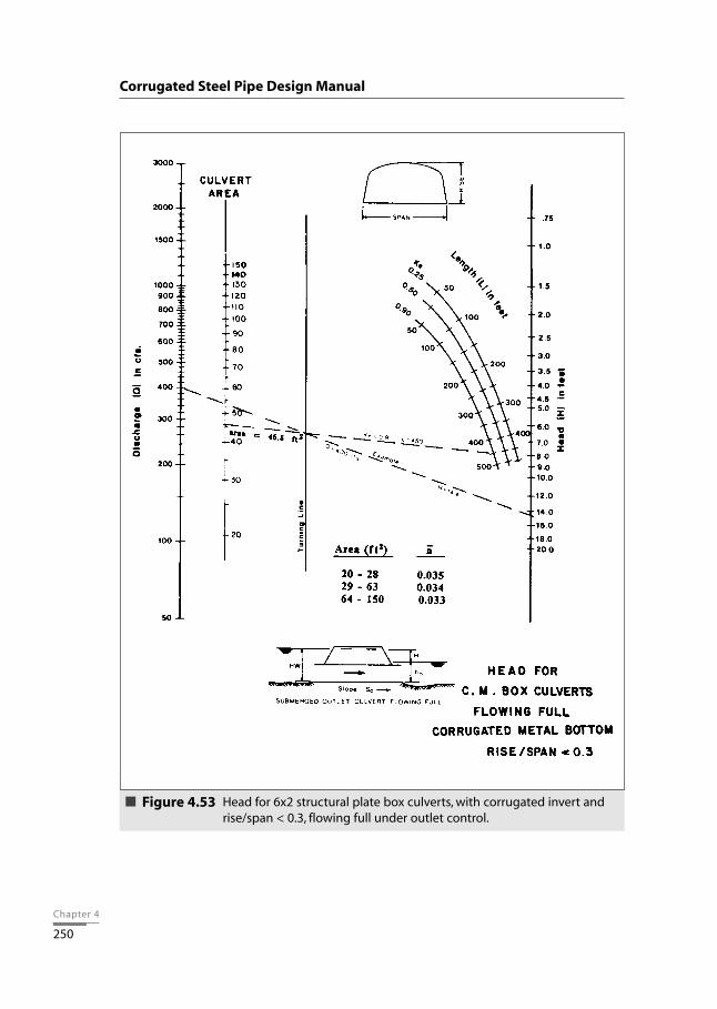
Chapter 4
250
Corrugated Steel Pipe Design Manual
Head for 6x2 structural plate box culverts, with corrugated invert andrise/span < 0.3, flowing full under outlet control.
Figure 4.53

Chapter 4
251
Hydraulic Design • Culverts
Head for 6x2 structural plate box culverts, with corrugated invert and0.3 <= rise/span < 0.4, flowing full under outlet control.
Figure 4.54

Chapter 4
252
Corrugated Steel Pipe Design Manual
Head for 6x2 structural plate box culverts, with corrugated invert and0.4 <= rise/span < 0.5, flowing full under outlet control.
Figure 4.55

Chapter 4
253
Hydraulic Design • Culverts
Head for 6x2 structural plate box culverts, with corrugated invert and0.5 <= rise/span, flowing full under outlet control.
Figure 4.56

Chapter 4
254
SPECIAL HYDRAULIC CONSIDERATIONSIn addition to flow hydraulics, the drainage designer must consider hydraulic forces andother hydraulic phenomena that may be factors in assuring the integrity of the culvert andembankment.
Uplifting ForcesUplifting forces on the inlet end of a culvert result from a variety of hydraulic factors thatmay act on the inlet during high flows. These may include: 1) Vortexes and eddy cur-rents that cause scour, which in turn undermine the inlet and erode the culvert support-ing embankment slope; 2) Debris blockage that accentuates the normal flow constriction,creating a larger trapped air space just inside the inlet, resulting in a significant buoyan-cy force that may lift the inlet; and 3) Sub-atmospheric pressures on the inside of theinlet, combined with flow forces or hydraulic pressures on the outside, that may cause theinward deflection of a skewed or beveled inlet, blocking flow and creating the potentialfor hydraulic uplift.
Corrugated Steel Pipe Design Manual
Hydraulic section parameters for structural plate box culverts.Figure 4.57

Chapter 4
255
Buoyancy type failures can be prevented by structural anchorage of the culvert entrance.This anchorage should be extended into the embankment both below and to the sides ofthe pipe. Cut-end treatment of the culvert barrel in bevels or skews should have hookbolts embedded in some form of slope protection to protect against bending.
PipingPiping is a hydraulic phenomena resulting from the submersion of the inlet end of a cul-vert and high pore pressure in the embankment. Hydrostatic pressure at the inlet willcause the water to seek seepage paths along the outside of the culvert barrel or throughthe embankment. Piping is the term used to describe the carrying of fill material, usual-ly fines, caused by seepage along the barrel wall. The movement of soil particles throughthe fill will usually result in voids in the fill. This process has the potential to cause fail-ure of the culvert and/or the embankment. Culvert ends should be sealed where thebackfill and embankment material is prone to piping.
Weep HolesThese are perforations in the culvert barrel which are used to relieve pore pressure in theembankment. Generally, weep holes are not required in culvert design. For an installa-tion involving prolonged ponding, there may be merit in considering a separate sub-drainage system to relieve pore pressure and control seepage in the embankment.
Anti-Seepage CollarsVertical cutoff walls may be installed around the culvert barrel at regular intervals to inter-cept and prevent seepage along the outer wall of the culvert. These may also be referredto as diaphragms. They are most often used in small earth fill dams or levees and are rec-ommended when ponding is expected for an extended time. An example of this is whenthe highway fill is to be used as a detention dam or temporary reservoir. In such cases,earth fill dam design and construction practices should be considered.
Single vs. Multiple OpeningsA single culvert opening is, in general, the most satisfactory because of its greater abilityto pass floating debris and driftwood. However, in many cases, the design requires thatthe waterway be wide in order to get the water through quickly without ponding andflooding of the land upstream. In such cases, the solution may consist of using either anarch, a pipe arch or a battery of two or more openings. See Figure 4.58.
Hydraulic Design • Culverts
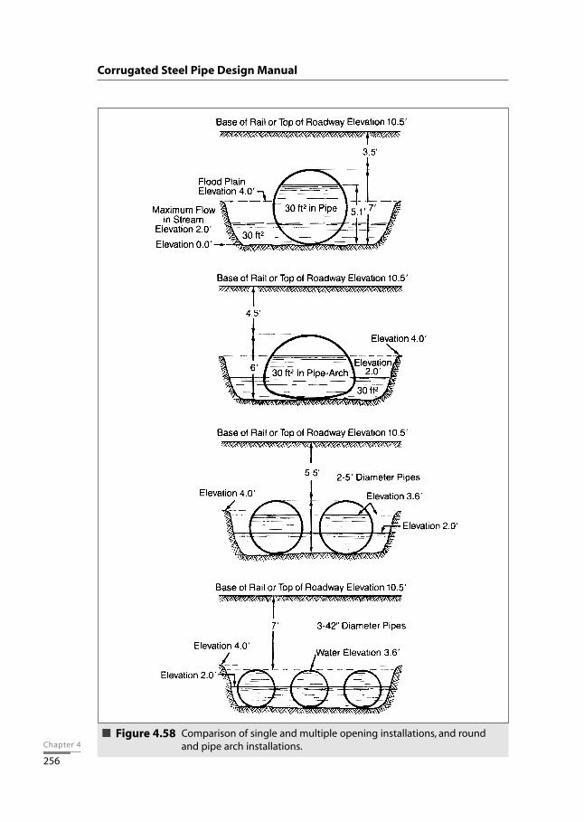
Chapter 4
256
Corrugated Steel Pipe Design Manual
Comparison of single and multiple opening installations, and roundand pipe arch installations.
Figure 4.58

Chapter 4
257
Hydraulic Design • Culverts
BIBLIOGRAPHY
AASHTO, “A Policy on Geometric Design of Highways and Streets”, American Associationof State Highway and Transportation Officials, 444 N. Capitol St., N.W., Ste. 249,Washington, D.C. 20001, 1994.
AASHTO, “Design of Roadside Channels with Flexible Linings,” Hydraulic EngineeringCircular No. 15, American Association of State Highway and Transportation Officials, 444N. Capitol St., N.W., Ste. 249, Washington, D.C. 20001.
AASHTO, “Highway Drainage Guidelines”, Vol. I - XIII, American Association of StateHighway and Transportation Officials, 444 N. Capitol St., N.W., Ste. 249, Washington,D.C. 20001, 1999.
Anon., “Drainage Management Manual”, Ministry of Transportation, Ontario, 1997.
ASCE, Design and Construction of Sanitary and Storm Sewers, American Society of CivilEngineers, 1986.
CSPI, Modern Sewer Design, Canadian Ed., Corrugated Steel Pipe Institute, 652 Bishop St.N., Unit 2A, Cambridge, Ontario, Canada N3H 4V6, 2002.
FHWA, “Capacity Charts for the Hydraulic Design of Highway Culverts,” HydraulicEngineering Circular No. 10, Federal Highway Administration, U.S. Department ofTransportation, 400 7th Street SW, Washington, D.C. 20590.
FHWA, “Culvert Analysis Program HY-8,” Federal Highway Administration, U.S.Department of Transportation, 400 7th Street SW, Washington, D.C. 20590
FHWA, “Hydraulic Charts for the Selection of Highway Culverts,” Hydraulic EngineeringCircular No. 12, Federal Highway Administration, U.S. Department of Transportation, 4007th Street SW, Washington, D.C. 20590.
FHWA, “Hydraulic Design of Energy Dissipaters for Culverts and Channels,” HydraulicEngineering Circular No. 14, Federal Highway Administration, U.S. Department ofTransportation, 400 7th Street SW, Washington, D.C. 20590.
FHWA, “Hydraulic Design of Highway Culverts,” Hydraulic Design Series No. 5, FederalHighway Administration, U.S. Department of Transportation, 400 7th Street SW,Washington, D.C. 20590.
FHWA, “Hydraulic Design of Highway Culverts”, Interactive Multimedia Document,FWHA-SA-96- 080, Federal Highway Administration, U.S. Department of Transportation,400 7th Street SW, Washington, D.C. 20590.
Smith, C. D., Hydraulic Structures, University of Saskatchewan Printing Services andUniversity Bindery, Saskatoon, Saskatchewan, Canada, 1995.

Pipe inspection.