Embed Size (px)
Citation preview
1
Contd…
CHAPTER-I
Induction Motor
Construction :
The induction motor mainly divided in to two parts.
(1) Stator (2) Rotor
In case of D. C. Motor basically it is divided into two main parts (i) Yoke (ii) Armature.
Yoke is outer & stationary part, similarly the outer portion of the induction motor is known as
stator. It is also stationary part of the induction motor. The stator of the induction motor is
cylindrical in shape.
The inner part of D. C. Motor i.e., armature is rotating in nature. Similarly the rotating
part of the induction motor is known as rotor. The rotor lies inside the stator. It is cylindrical in
shape.
Rotor is divided into two types.
(i) Squirrel cage Rotor
(ii) Phase wound Rotor or Slip ring Rotor,
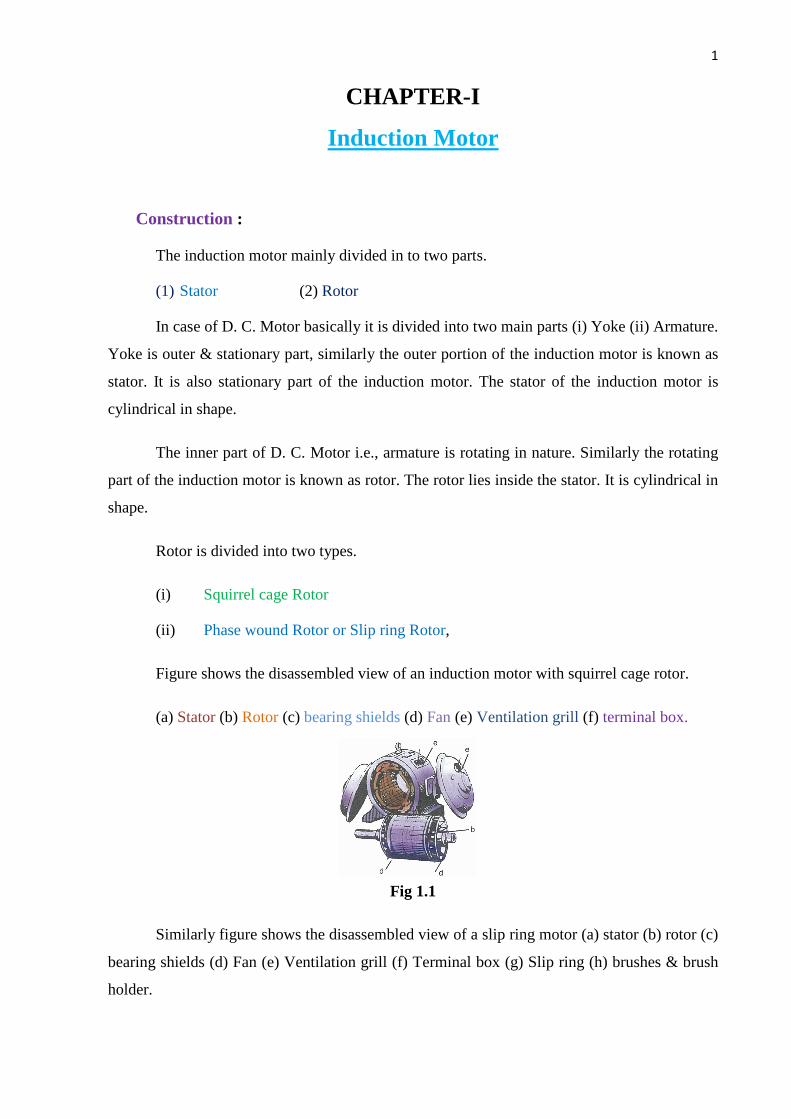
Figure shows the disassembled view of an induction motor with squirrel cage rotor.
(a) Stator (b) Rotor (c) bearing shields (d) Fan (e) Ventilation grill (f) terminal box.
Fig 1.1
Similarly figure shows the disassembled view of a slip ring motor (a) stator (b) rotor (c)
bearing shields (d) Fan (e) Ventilation grill (f) Terminal box (g) Slip ring (h) brushes & brush
holder.
2
Contd…
Production of Rotating Magnetic Field :
When 3 – phase stationary coils are fed with 3 – phase supply, a uniformly rotating
magnetic flux of constant magnitude will produce.
It will now be shown that when three – phase winding displaced in space by 1200, are
fed by three phase currents, displaced in time by 1200, they produce a resultant magnetic flux,
which rotates in space as if actual magnetic poles were being rotated mechanically.
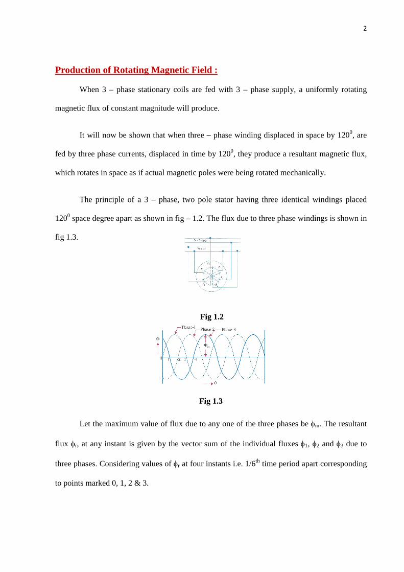
The principle of a 3 – phase, two pole stator having three identical windings placed
1200 space degree apart as shown in fig – 1.2. The flux due to three phase windings is shown in
fig 1.3.
Fig 1.2
Fig 1.3
Let the maximum value of flux due to any one of the three phases be fm. The resultant
flux fr, at any instant is given by the vector sum of the individual fluxes f1, f2 and f3 due to
three phases. Considering values of fr at four instants i.e. 1/6th time period apart corresponding
to points marked 0, 1, 2 & 3.

3
Contd…
Proof :
Case – 1 : Resultant flux at origin i.e. when q = 00 At that time f1 = 0,
f2 = fm Sin < - 1200 = 23
- fm f3 = fm Sin < - 2400 = 23
- fm.
Fig 1.4
Resultant flux fr :
As per law of parallerogram
2rf
= 2
2f + 23f + 2 f2 × f3 × cos 600
Þ 2rf =
2
m23
÷÷ø
öççè
æf +
2
m23
÷÷ø
öççè
æf + 2.
23
fm × 23
fm 21
Þ 2rf = 2
m43f + 2
m43f + 2
m43f
Þ 2rf = 2
m49f
Þ rf = m23f
Þ fr = 1.5 fm
Case – II : When q = 600
Therefore f1 = fm Sin < 600 = 23
fm

4
Contd…
f2 = fm Sin < - 1200 + 600 = fm Sin < - 600 = 2
3- fm
and f3 = fm Sin < - 2400 + 600 = fm Sin < - 180 = 0
case – III When q = 1200
f1 = fm Sin < 1200 = 23
fm
f2 = fm Sin < - 1200 + 1200 = fm Sin < 00 = 0
f3 = fm Sin < - 2400 + 1200 = fm Sin < - 1200 = 2
3- fm
fr can be calculated as earlier
Similarly fr = 1.5fm
Case – IV When q = 1800
f1 = fm Sin < 1800 = 0
f2 = fm Sin < - 1200 + 1800 = fm Sin < 600 = 23
fm
f3 = fm Sin < - 2400 + 1800 = fm Sin < - 600 = 2
3- fm
Similarly fr can be calculated as earlier fr = 1.5 fm
Hence from the above four cases we can draw a conclusion that the resultant flux (fr)
inside the stator winding at any time = 1.5 fm and the resultant flux (fr) rotates around the
stator at syncronous speed.
How the rotor rotates :
The rotor lies inside the stator. There is an air gap in between the stator and rotor. The
stator slots are provided with three Phase winding.
When three phase stator windings are fed by a 3-phase supply then a rotating magnetic
flux of constant magnitude will produce.
This rotating flux passes through air gap and cuts the stationary conductors on the rotor
. There is also a 3-phase rotor winding on the rotor. The stator and rotor windings act as

5
Contd…
primary and secondary windings of a 3-phase transformer. The air gap acts as core of the
transformer. The fluxes passes from stator to rotor winding through induction principle.
The rotating flux produces an emf in the rotor winding. The rotor winding is closed
circuit. Hence current will flow in the rotor conductors. When current will flow it will produce
the flux in the air gap. The flux in the rotor winding interacts with the flux in the stator winding
there by producing a torque, which is responsible for the rotation of the rotor.
Slip(s) :
The rotor never succeeds in catching up with the stator field. It is really did so, then there
would be no relative speed between the two, hence no rotor emf, no rotor current and so no
torque to maintain rotation. That in why the rotor runs at a speed which is always less than the
speed of the stator field.
The difference between synchronous speed Ns to the actual speed of the totor Nr is known as
slip speed.
Slip speed = Ns – Nr.
Slip (s) or % of Slip (s) = 100N
NN
s
rs ´-
s
rs
NNN
S-
=Þ
ÞNs – Nr = SNs
ÞNs – SNS = Nr
ÞNs(1-S) = Nr
Therefore Rotor speed Nr = Ns (1-S)
Frequency of Rotor Current :
When the rotor is stationary, the frequency of rotor current is the same as the supply frequency.
But when the rotor starts revolving, then the frequency depends upon the relative speed. Let the
frequency of the rotor current be f¢.
Hence Ns - Nr =P
f '120=
6
Contd…
As Ns = P
f120=
f
PP
fN
NN '
s
rs
120120
´=-
Þ
ff
S'
=Þ
Therefore f' = Sf
Hence Rotor frequency = slip x supply frequency
Torque of an Induction Motor :
The torque of an induction motor is the torque produced at the rotor. Hence T=Tr where
Tr is the rotor torque.
In case of D.C. motor torque = Armature Torque = Ta
Ta = 0.159fZIa ÷øö
çèæ
AP
N×m
There fore Ta = KfIa
[Where 0.159, Z, P and A are all constants)
Where f is the flux produced by the filed winding which is pulsating in nature.
Similarly in case of an induction motor the torque is also proportional to the product of
flux produced in stator and rotor current.
However there is another factor which is to be taken is power factor. Because in this
case both flux and current are alternating in nature.
Therefore Tr a f I2 cos f2
Where I2 – Rotor Current
f - flux produced in the stator.
f2 – The phase angle between rotor emf and rotor current (E2 and I2)
As f a E2
Therefore Tr = T a E2 I2 cos f2

7
Contd…
T = K E2 I2 cos f2
Starting Torque :
The torque developed by the motor at the instant of starting is called starting torque.
Let E2 = Rotor emf per phase at stand still
R2 = Rotor resistance / phase
X2 = Rotor reactance / phase at stand still
Z2 = 22
22 XR + = Rotor impedance / phase at stand still
Then I2 = 2
2
ZE
= 22
22
2
XR
E
+, cos f2 =
2
2
ZR
= 22
22
2
XR
R
+
Stand still or starting torque Tst = K E2 I2 cos f2
Or Tst = K E2 × 2
22
2
RR
E
+ ×
222
2
RR
R
+ =
222
222
RRR E K
+
If supply voltage V remains constant, then the flux f and hence E2 remain constant.
Therefore Tst = 22
22
21 XR
R K
+
Þ Tst = 22
21 Z
R K
Starting Torque of a Squirrel – cage Induction Motor :
The resistance of a squirrel cage motor is fixed and small as compared to its reactance
which is very large especially at the start because at stand still, the frequency of the rotor
currents equal the supply frequency. Hence the starting current I2 of the rotor, though very
large in magnitude, laggs by a very large angle E2, with the result that the starting torque per
ampere is very poor. Hence, such motors are not useful where the motor has to start against
heavy loads.
Starting Torque of a slip-ring motor :
The starting torque of such motor is increased by improving its power factor by adding
external resistance in the rotor circuit from the star connected rheostat, the rheostat resistance
8
Contd…
being progressively cut out as the motor gathers speed. Addition of external resistance,
however increases the rotor impedance and so reduces the rotor current. At first, the effect of
improved power factor predominates the current–decrearing effect of impedance. Hence,
starting torque is increased. But after a certain point, the effect of increased impedance
predominates the effect of improved power factor and so the torque starts decreasing.
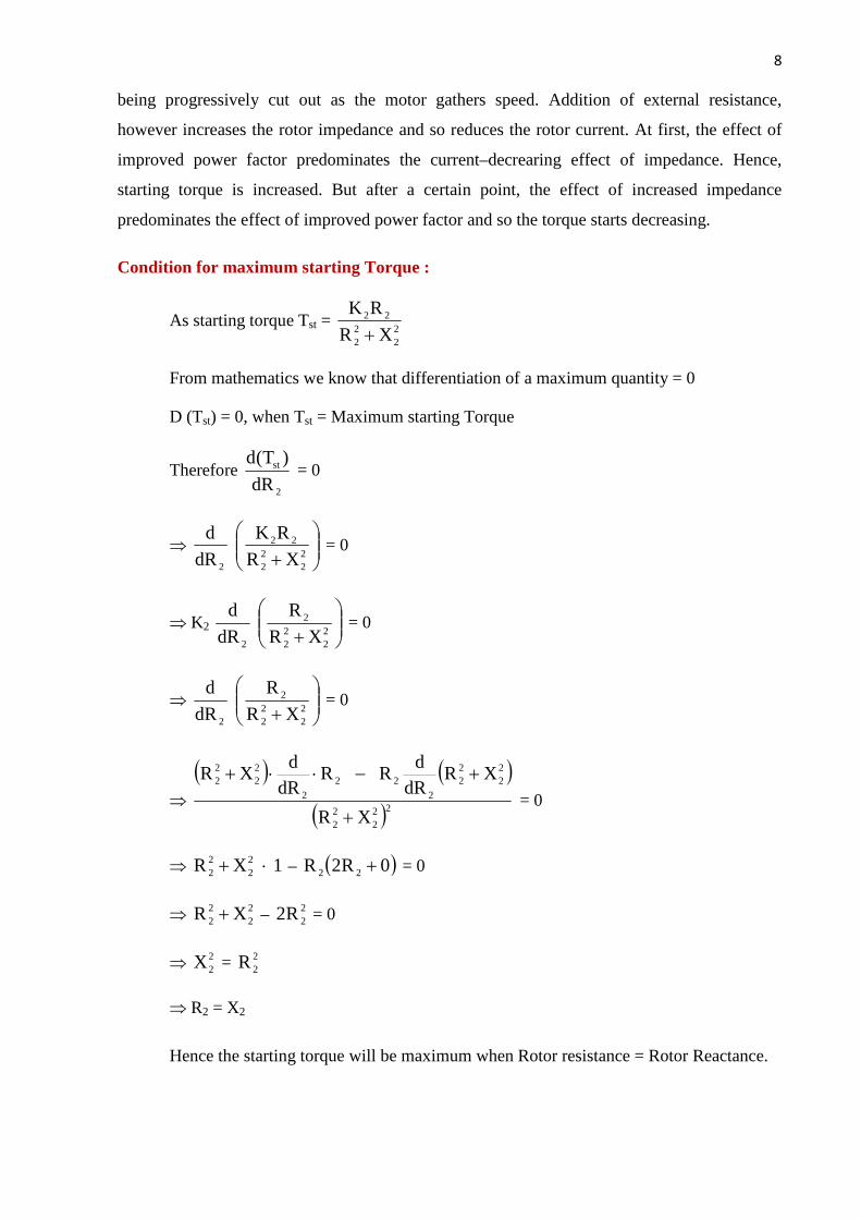
Condition for maximum starting Torque :
As starting torque Tst = 22
22
22
XRRK+
From mathematics we know that differentiation of a maximum quantity = 0
D (Tst) = 0, when Tst = Maximum starting Torque
Therefore 2
st
dR)T(d
= 0
Þ ÷÷ø
öççè
æ+ 2
222
22
2 XRRK
dR
d = 0
Þ K2 ÷÷ø
öççè
æ+ 2
222
2
2 XRR
dR
d = 0
Þ ÷÷ø
öççè
æ+ 2
222
2
2 XRR
dR
d = 0
Þ
( ) ( )
( )222
22
22
22
222
2
22
22
XR
XRdR
dR R
dRd
XR
+
+-××+ = 0
Þ 1 XR 22
22 ×+ – ( )0R2R 22 + = 0
Þ 22
22 XR + – 2
2R2 = 0
Þ 22X = 2
2R
Þ R2 = X2
Hence the starting torque will be maximum when Rotor resistance = Rotor Reactance.
9
Contd…
Rotor EMF and Rotor reactance under running condition :
Rotor EMF : Let E2 = Stand still rotor EMF / phase
X2 = Stand still rotor reactance / phase
When rotor starts rotating, the relative speed between rotor and rotating flux in the
stator starts decreasing.
Slip (s) = s
rs
NNN -
The rotor induced emf is directly proportional to this relative speed
i.e. Er a (Ns – Nr) E2
Þ Er = K (Ns – Nr) E2
Þ Er = s
rs
NNN -
× E2
Therefore Er = SE2
Rotor Reactance :
The frequency of the rotor current
fr = sf
Therefore Xr = 2psfrL
Þ Xr = 2 psfL
Þ Xr = S (2pfL)
Therefore Xr = S X2
Torque under running conditions :
As we know that starting torque Tst = KE2I2 cos f2
Therefore Tst a E2 I2 cos f2
So the torque under running condition Tr a Er Ir cos fr
Where Er = Rotor EMF/Phase under running condition
Ir = Rotor Current/Phase under running condition
As Er a f
Therefore Tr a f Ir × cos fr

10
Contd…
Ir = r
r
ZE
But Zr = R2 + j Xr = R2 + j SX2
Cos fr = ( )22
22
2
SXR
R
+ and Ir =
( )2222
2
SXR
SE
+
Therefore running torque Tr a Er Ir as fr
Therefore Tr a f 2
222
2
22
22
2
)XS(R
R
)XS(R
SE
×+×
×+
Þ Tr a f 2
222
22
)XS(RRSE×+
Þ As E2 a f
Otenu Tr a 2
222
222
)XS(RRSE×+
Therefore Tr = 2
222
2221
)XS(RRSEK×+
Torque under stand still condition :
Nr = 0 at stand still condition
S = S
S
N
0N -= 1
Therefore torque under stand still condition
Tr = 22
22
2221
XRR E K
+
Condition for maximum Torque under running condition :
The torque of a rotor under running condition
Tr = 2
222
2221
)XS(RRSEK×+
The conditions for maximum torque may be obtained by differentiating the above
equation w.r.t slip (s) and then putting it equal to zero.
11
Contd…
Let Y = rT
1 (For to make the differentiation easy)
Therefore Y = ( )
2221
2
222
RSEKSXR +
Þ Y = 221
2
SEKR
+ 2
221
22
REKSX
For maximum torque under running condition dSdY
= 0
Þ ÷÷ø
öççè
æ221
2
SEKR
dSd
+ ÷÷ø
öççè
æ
2221
22
REKSX
dSd
= 0
Þ ÷÷ø
öççè
æ22
2
SER
dSd
+ ÷÷ø
öççè
æ
222
22
RESX
dSd
= 0
Þ ( )
( )222
222
22
2
E S
SEdSd
R SEdS
dR-×
+ ( ) ( )
( )2222
222
222
22
22
RE
SXRE dSd
RE SE dSd
×-× = 0
Þ 42
22
22
E SRE 0 ×-
+ 22
42
222
22
R E0 REX -
= 0
Þ 42
2
222
E SER -
+ 2
22
22
R EX
= 0
Þ 22
22
E SR
= 2
22
22
REX
Þ 22
SR
= 2
22
RX
Þ 22R = 2
22XS
Therefore R2 = SX2
Hence the torque under running condition will be maximum when R2 = SX2
As the torque under running condition
Tr = ( )22
22
2221
SXR
RSEK
+

12
Contd…
Putting the value R2 = SX2
Therefore Tr = Tr (max) = ( ) ( )22
2
2
222
SXSX
SX SE K
+×
Þ Tr (max) = 22
22
22
2
XS2XEKS
= 2
22
X2E K
Hence Tr (max) = 2
22
X2E K
Relation between full load Torque and Maximum Torque :
As Torque (T) = ( )22
22
2221
SXR
R SE K
+
E2 is practically constant
Hence T = ( )22
22
22
SXR
SR K
+
Therefore T a ( )22
22
2
SXR
SR
+
Taking full load slip as Sf at full load torque Tf
Therefore Tf a ( )22
22
2f
SXR
RS
+ ………. (I)
As Tmax = 2
22
X2E K
Tmax a 2X2
1 ……….. (II)
)ii()i(
= max
f
TT
= ( )22f
22
2f
XSR
R S
+ ´
1X2 2
max
f
TT
= ( )22f
22
22f
XSR
XRS2
+
Dividing 22X on both side

13
Contd…
Þ max
f
TT
= 2f2
2
22
2
2f
SXR
XR
S2
+
Taking aXR
2
2 =
Þ 2f
2f
max
f
SaaS2
TT
+=
In general 22 as
as2
Torque MaximumTorque operating
+=
s – operating slip
Relation between starting Torque and Maximum Torque :
As 22
22
2st XR
RK T
+=
22
22
2st XR
R T
+aÞ …………………. (i)
But 2
max X21
T a …………………. (ii)
12X
XR
R
T
T
(ii)(i) 2
22
22
2
max
st ´+
==
22
22
22
max
st
XRX2R
TT
+
=Þ
22
22
22
22
22
22
max
st
XX
XR
XX2R
TT
+
=Þ
1
XR
X2R
TT
2
2
2
2
2
max
st
+÷÷ø
öççè
æ=Þ

14
Contd…
1aa2
TT
2
max
st
+=Þ
Relation between Torque and slip :
As Torque (T) = 2
222
222
)(SXRRKSE
+
Taking Torque in Y axis and slip in X axis
At origin i.e. S = 0, torque T = 0
Therefore the curve starts from origin. At normal speed, closed to synoronism that is
when Nr is very near to Ns, then slip is very nearly equal to zero.
Therefore SX2 << R2
22
222
RRSE
T aÞ Neglecting (SX2)2
(Taking supply voltage constant so E2 is also constant)
2R
S T aÞ
For a particular induction motor R2 is constant.
Hence T a S
Therefore low valve of slip, torque is directly proportional to slip. Hence the curve is
straight line for low valve of slip.
As slip increases the torque also increases and becomes maximum when = R2 = SX2
i.e. 2
2
XR
S =
As the slip further increases (SX2) becomes higher compare to R2.
Hence R2 can be neglected in compare to (SX2)
Fig. 1.5
15
Contd…
( )22SX
S T aÞ
22SX
1 T aÞ
Taking X2 is constant for a particular induction motor
Therefore S1
T a
So beyond the point of maximum torque any further increase in slip, results in decrease of
torque.
Method of standing of Induction Motor
The operation of the squirrel cage induction motor is similar to transformer having
short circuited on the secondary side.
Due to short circuited on the rotor circuit it will take heavy current when it is directly
switched on. Generally when direct switched, take five to seven times of their full load current.
This initial excessive current is objectionable, because it will produce large line voltage drop.
Hence it is not advisable to start directly motors of rating above 5 KW. But the starting
torque of an induction motor can be improved by increasing the resistance of the rotor circuit.
This is easily feasible in the case of slip ring induction motor but not in the case of squirrel
cage motors. However, in their case, the initial in rush of current is controlled by applying a
reduced voltage to the stator during the starting period, full normal voltage being applied when
the motor has run up to speed.
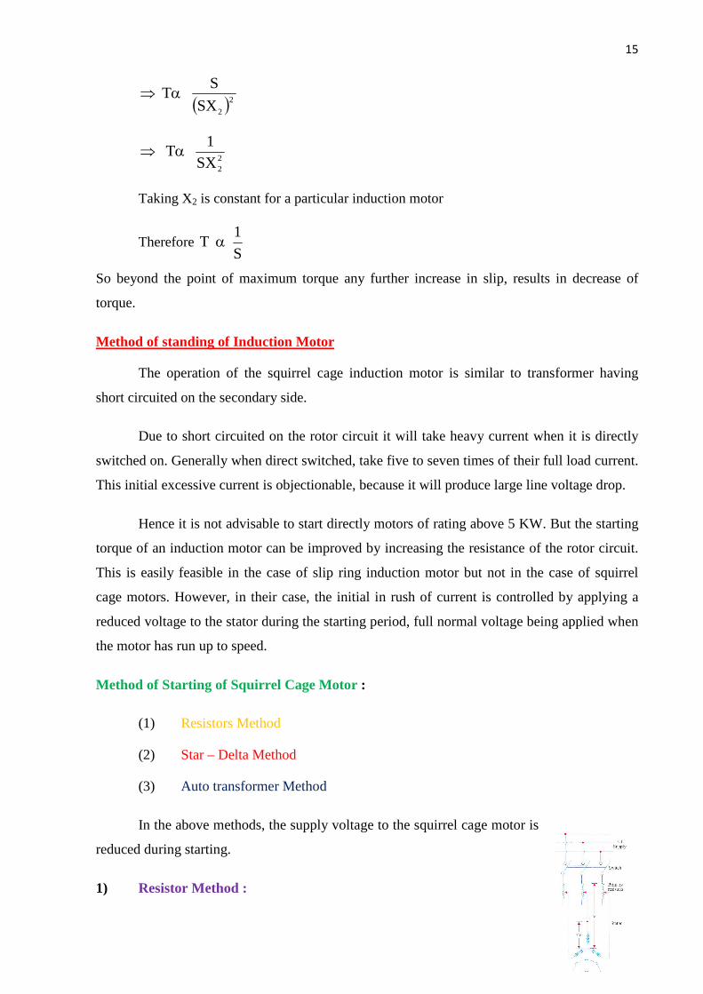
Method of Starting of Squirrel Cage Motor :
(1) Resistors Method
(2) Star – Delta Method
(3) Auto transformer Method
In the above methods, the supply voltage to the squirrel cage motor is
reduced during starting.
1) Resistor Method :

16
Contd…
In this method the resistors are connected in series with the stator phases, to give
reduced voltage to the stator winding.
When resistors are connected in series with the stator phases, the current in the stator
phases will reduce. If the voltage applied across the motor terminals is reduced by 50%,
starting current is reduced by 50%.
When the motor starts running the resistances in the circuit is gradually cut out and full
voltage is applied to the stator circuit. This method is useful for the smooth starting of small
machines only.
2) Star – Delta Starter :
This method is used in the case of motors which are built to run
normally with a delta connected stator winding. It consists of a two way
switch which connects the motor in star for starting and then in delta
for normal running.
At starting, when star connected, the applied voltage over each
motor phases is reduced by afactor 3
1 . Hence during starting, when
motor is star connected it takes 3
1 times as much as starting current.
When the motor catches the speed 80% of its normal speed switch is changed to delta
positions at that time VL = Vph.
Auto Transformer Method :
This starter is popularly known as auto starter in auto
transformer the secondary side gets less voltage in compare to
primary side.
As shown in the figure, at starting condition, a reduced
voltage is applied across the mo terminals. When the motor
catches the speed 80% of its normal speed, connections are
changed to running position, then full supply voltage is
applied across the motor.
Fig 1.6
Fig 1.7
Fig 1.8

17
Contd…
Most of the auto starters are provided with 3 – sets of taps so as to reduced the voltage
to 80, 65 or 50 percent of line voltage.
Slip ring Motor :
Rotor Rheostat Method :
These motors are practically always started with full line voltage applied across the
stator terminals. The value of starting current is adjusted by introducing a variable resistance in
the rotor circuit.
Fig 1.9
The controlling resistance is in the form of a rheostat, connected in star, the resistance
being gradually cut – out of the rotor circuit, as the motor gathers speed
Speed Control of Induction Motor :
The speed of an induction motor can be changed under two main headings.
(i) Control from stator side
(ii) Control from Rotor side
(i) Control from stator side :
(a) By changing the applied voltage
(b) By changing the applied frequency
(c) By changing the no of stator poles.

18
Contd…
(ii) Control from Rotor side :
(a) Rotor Rheostatic Control
(b) Cascade operation
(c) By injecting emf in the rotor circuit
By changing applied voltage :
This method is the easiest way for controlling speed of an induction motor. But this
method is rarely used for the following reasons.
(i) A large change in voltage is required for a small change in speed.
(ii) Due to the connection of resistances in the stator phases, large power loss occurs at
the resistors.
When the resistances are added in the stator circuit, voltage across the stator phase
decreases.
As torque (T) = 22
22
22
XRRKV
+
Þ Torque T = K1 V2
Þ T a V2
The torque depends on the supply voltage on the stator terminals, when V will decrease
T will decrease hence speed will decrease.
By Charging the number of stator poles :
This method is easily applicable to squirrel cage motors because the squirrel cage rotor
adopts it self to any reasonable number of stator poles.
The change in number of stator poles is achieved by having two more entirely
independent stator windings in the same slots. Each winding gives a different number of poles
and hence different synchronous speed.
Rotor Rheostatic Control :
This method is applicable to slip ring motors alone. The motor speed is reduced by
introducing an external resistance in the rotor circuit.
Fig 1.10
19
Contd…
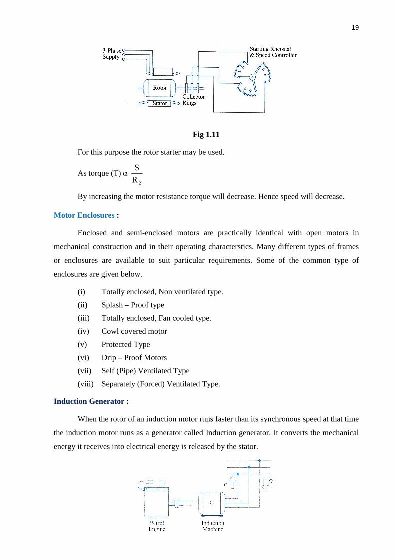
Fig 1.11
For this purpose the rotor starter may be used.
As torque (T) a 2R
S
By increasing the motor resistance torque will decrease. Hence speed will decrease.
Motor Enclosures :
Enclosed and semi-enclosed motors are practically identical with open motors in
mechanical construction and in their operating characterstics. Many different types of frames
or enclosures are available to suit particular requirements. Some of the common type of
enclosures are given below.
(i) Totally enclosed, Non ventilated type.
(ii) Splash – Proof type
(iii) Totally enclosed, Fan cooled type.
(iv) Cowl covered motor
(v) Protected Type
(vi) Drip – Proof Motors
(vii) Self (Pipe) Ventilated Type
(viii) Separately (Forced) Ventilated Type.
Induction Generator :
When the rotor of an induction motor runs faster than its synchronous speed at that time
the induction motor runs as a generator called Induction generator. It converts the mechanical
energy it receives into electrical energy is released by the stator.

20
Contd…
Fig 12
Figure shows a ordinary squirrel cage induction motor which is driven by a petrol
engine and is connected to a 3 – phase line. As soon as motor speed exceeds its synchronous
speed, it starts delivering active power P to the 3 – phase line. However, for creating its own
magnetic field, it absorbs reactive power Q from the line to which it connected.
-0-
21
Contd…
CHAPTER-II
(Alternators)
INTRODUCTION
An alternating voltage is generated in a single conductor/coil rotating in a uniform
magnetic field with stationary field poles .Similarly, an alternating voltage will also be
generated in a stationary conductor/coil when the field poles rotate past the conductor/coil
, as it is the relative motion between the field and the conductor/coil that matters so far as
emf induction in a conductor/coil is concerned. The wave shapes of voltage in both the cases
are sinusoidal as the wave shape of magnetic flux is sinusoidal.
In D.C. generators , the field poles are stationary and the armature conductors
rotate.The voltage generated in the armature conductors is of alternating nature. This
generated alternating voltage is converted to a direct voltage at the brushes with the help of the
commutator.
A.C. generators are usually called Alternators. They are also called Synchronous
generators. Rotating machines that rotate at a speed fixed by the supply frequency and the
number of poles are called synchronous machines.
A synchronous generator is a machine for converting mechanical power from a prime
mover to ac electric power at a specific voltage and frequency .A synchronous machine rotates
at a constant speed called the synchronous speed.Synchronous machines are usually of 3-
phase type because of various advantages of 3-phase Generation,Transmission and
Distribution.Large synchronous generators of several MVA ratings are used to generate bulk
power at thermal ,hydro and nuclear power stations.
ADVANTAGES OF ROTATING FIELD ALTERNATOR
Most alternators have the rotating field and the stationary armature.The rotating-field
type alternator has several advantages over the rotationg-armature type alternator.
(1) A stationary armature is more easily insulated for the high yoltage for which the
alternator is designed. This generated voltage may be as high as 33KV.
(2) The armature windings can be braced better mechanically against high electro-magnetic
forces due to large short-circuit currents when the armature windings are in the stator.
(3) The armature windings, being stationary, are not subjected to vibration and centrifugal
forces.
22
Contd…
(4) The output current can be taken directly from fixed terminals on the stationary armature
without using slip rings, brushes, etc.
(5) The rotating field is supplied with direct current. Usually the field voltage is between
100 to 500 volts. Only two slip rings are required to provide direct current for the
rotating field while at least three slip rings would be required for a rotating armature.
The insulation of the two relatively low voltage slip rings form the shaft can be
provided easily.
(6) The bulk and weight of the armature windings are substantially greater than the
windings of the field poles. The size of the machine is, therefore, reduced.
(7) Rotating field is comparatively light and can be constructed for high speed rotation.
The armatures of large alternators are forced cooled with circulating gas or liquids.
(8) The stationary armature may be cooled more easily because the armature can be made
large to provide a number of cooling ducts.
SPEED AND FREQUENCY
The frequency of the generated voltage depends upon the number of field poles and on
the speed at which the field poles are rotated. One compete cycle of voltage is generated in an
armature coil when a pair of field poles (one north and one south pole) passes over the coil.
Let P =total number of field poles
P= pair of field poles
N= speed of the field poles in r.p.m.
n=speed of the field poles in r.p.s.
f= frequency of the generated voltage in Hz
Obviously = n ……………………………………………….. 1.1
and = p ………………………………………………………………1.2
In one revolution of the rotor, an armature coil is cut by north poles and south poles. Since
one cycle is generated in an armature coil when a pair of field poles passes over the coil, the
number of cycles generated in one revolution of the rotor will be equal to the number of pairs
of poles. That is,
23
Contd…
Number of cycles per revolution = p
Also, number of revolutions per second=n
Now frequency=number of cycles per second
= X
f= p x n ………………………………………………………… 1.3
Since n =N/60 and p=p/2
f= …………………………………………………….. 1.4
Equation(1.2) and (1.4) give the relationship between the number of poles, speed and
frequency.
SYNCHRONOUS SPEED
From Eq.(1.4)
Ns= ………………………..(1.5)
Equation (1.5) shows that the rotor speed N bears a constant relationship with the field
poles and the frequency of the generated voltage in the armature winding. The speed given by
Eq. (1.5) us called synchronous speed . A machine which runs at synchronous speed is
called synchronous machine. Thus, a synchronous machine is an a.c. machine in which the
rotor moves at a speed which bears a constant relationship to the frequency of the generated
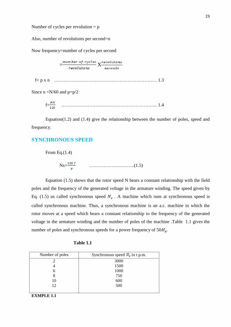
voltage in the armature winding and the number of poles of the machine .Table 1.1 gives the
number of poles and synchronous speeds for a power frequency of 50 .
Table 1.1
EXMPLE 1.1
Number of poles Synchronous speed in r.p.m.
2 4 6 8 10 12
3000 1500 1000 750 600 500

24
Contd…
Calculate the highest speed at which (a) 50 (b) alternator can be
operated.
Solution
Since it is not possible to have fewer than 2 poles, the minimum value of p= 2.
f =
=
For a minimum value of P the speed N will be a maximum.
(a) f= 50 Hz, p=2
= = 3000r.p.m.(Ans.)
(b) f=60 Hz, p=2
= = 3600r.p.m.(Ans.)
CONSTRUCTION OF THREE-PHASE SYNCHRONOUS
MACHINES
Similar to other rotating machines, an alternator consists of two main parts namely, the
stator and the rotor. The stator is the stationary part of the machine. It carries the armature
winding in which the voltage is generated. The output of the machine is taken from the stator.
The rotor is the rotating part of the machine. The rotor produces the main field flux.
STATOR CONSTRUCTION
The various parts of the stator include the frame, stator core, stator windings and
cooling arrangement. The frame may be of cast iron for small-size machines and of welded
steel type for large size machines. In order to reduce hysteresis and Eddy-current losses, the
stator core is assembled with high grade silicon content steel laminations. A 3-phase winding
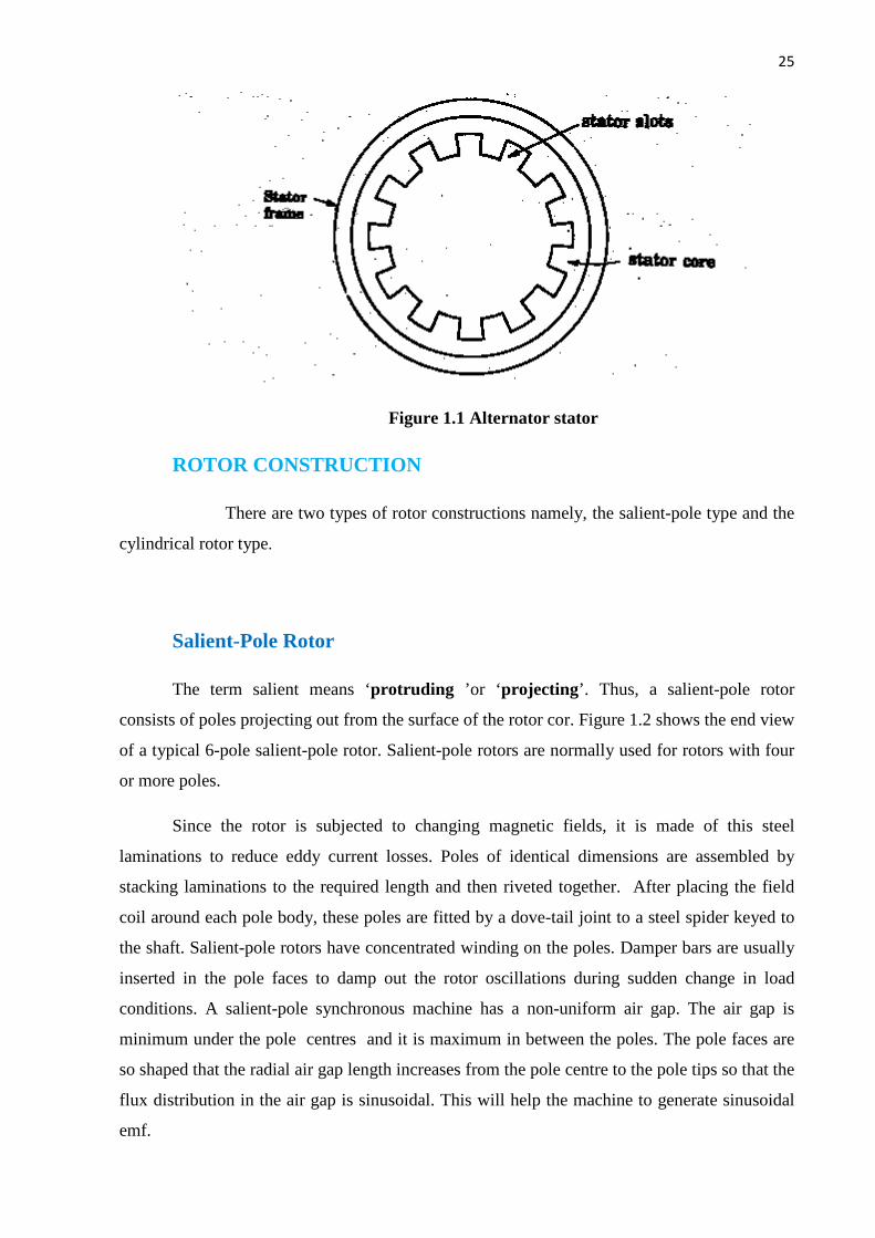
is put in the short cut on the inner periphery of the stator as shown in Fig.1. The winding is
star connected. The winding of each phase is distributed over slots . When current flows in a
distributed winding it produces an essentially sinusoidal space distribution of emf.
25
Contd…
Figure 1.1 Alternator stator
ROTOR CONSTRUCTION
There are two types of rotor constructions namely, the salient-pole type and the
cylindrical rotor type.
Salient-Pole Rotor
The term salient means ‘protruding ’or ‘projecting’. Thus, a salient-pole rotor
consists of poles projecting out from the surface of the rotor cor. Figure 1.2 shows the end view
of a typical 6-pole salient-pole rotor. Salient-pole rotors are normally used for rotors with four
or more poles.
Since the rotor is subjected to changing magnetic fields, it is made of this steel
laminations to reduce eddy current losses. Poles of identical dimensions are assembled by
stacking laminations to the required length and then riveted together. After placing the field
coil around each pole body, these poles are fitted by a dove-tail joint to a steel spider keyed to
the shaft. Salient-pole rotors have concentrated winding on the poles. Damper bars are usually
inserted in the pole faces to damp out the rotor oscillations during sudden change in load
conditions. A salient-pole synchronous machine has a non-uniform air gap. The air gap is
minimum under the pole centres and it is maximum in between the poles. The pole faces are
so shaped that the radial air gap length increases from the pole centre to the pole tips so that the
flux distribution in the air gap is sinusoidal. This will help the machine to generate sinusoidal
emf.

26
Contd…
Figure 1.2 Six-pole salient-pole rotor
The individual field-pole windings are connected in series to give alternate north and
south polarities. The ends of the field windings are connected to a dc source(a dc generator or a
rectifier)through the brushes on the slip rings. The slip rings are metal rings mounted on the
shaft and insulated from it. They are used to carry current to or from the rotating part of the
machine (usually ac machine) via carbon brushes.
Salient-pole generators have a large number of poles at lower speeds. A salient-
pole generator has comparatively a large diameter and a short axial length. The large diameter
accommodates a large number of poles.
Salient-pole alternators driven by water turbines are called hydro-alternators or
hydro-generators. Hydro-generators with relatively higher speeds are used with impulse
turbines and horizontal configuration. Hydro-generators with lower speeds are used with
reaction and Kaplan turbines and have vertical configuration.
Cylindrical Rotor
A cylindrical-rotor machine is also called a non-salient pole rotor machine. It has
rotor so constructed that it forms a smooth cylinder. The construction is such that there are no
physical poles to be seen as in the salient-pole construction. Cylindrical rotors are made from
solid forgings of high grade nickel-chrome-molybdenum steel. In about two-third of the rotor
periphery, slots are cut at regular intervals and parallel to the shaft. The dc field windings are
accommodated in these slots. The winding is of distributed type. The un slotted portion of the
rotor forms two (or four) pole faces. A cylindrical rotor machine has a comparatively small
27
Contd…
diameter and long axial length. Such a construction limits the centrifugal forces. Thus,
cylindrical rotors are particularly useful in high-speed machines. The cylindrical rotor type
alternator has two or four poles on the rotor. Such a construction provides a greater mechanical
strength and permits more accurate dynamic balancing. The smooth rotor of the machine
makes less windage losses and the operation is less noisy because of uniform air gap.
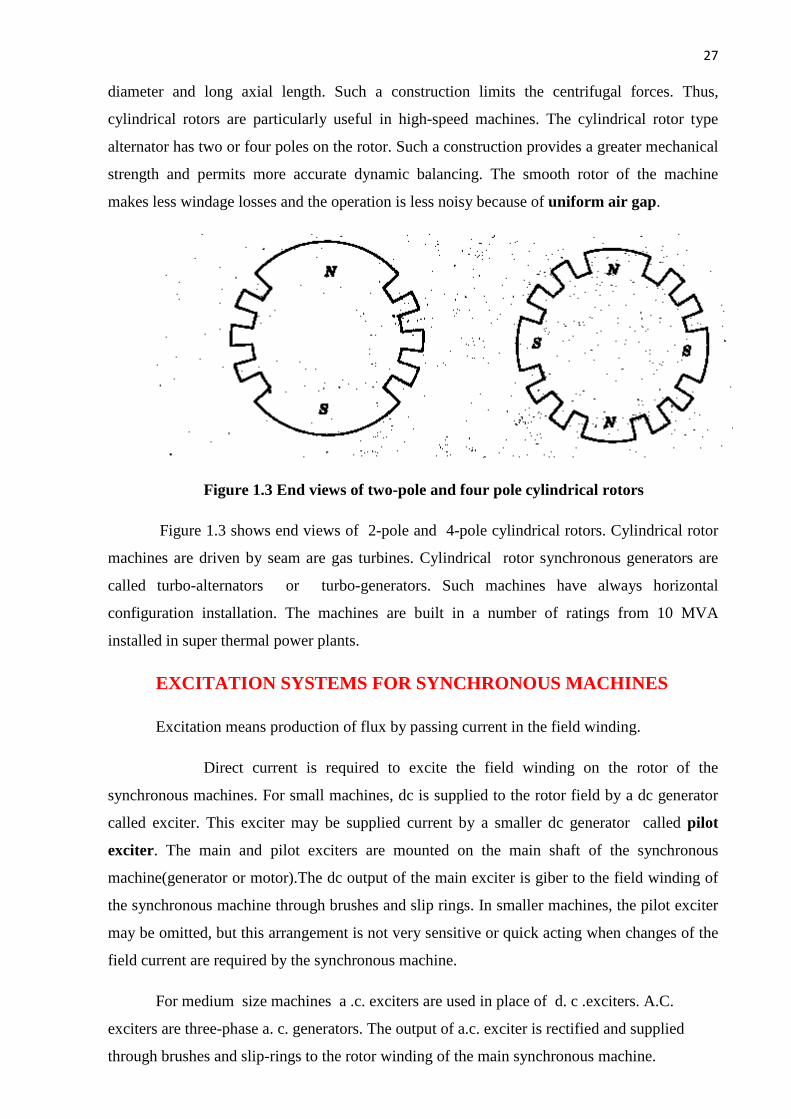
Figure 1.3 End views of two-pole and four pole cylindrical rotors
Figure 1.3 shows end views of 2-pole and 4-pole cylindrical rotors. Cylindrical rotor
machines are driven by seam are gas turbines. Cylindrical rotor synchronous generators are
called turbo-alternators or turbo-generators. Such machines have always horizontal
configuration installation. The machines are built in a number of ratings from 10 MVA
installed in super thermal power plants.
EXCITATION SYSTEMS FOR SYNCHRONOUS MACHINES
Excitation means production of flux by passing current in the field winding.
Direct current is required to excite the field winding on the rotor of the
synchronous machines. For small machines, dc is supplied to the rotor field by a dc generator
called exciter. This exciter may be supplied current by a smaller dc generator called pilot
exciter. The main and pilot exciters are mounted on the main shaft of the synchronous
machine(generator or motor).The dc output of the main exciter is giber to the field winding of
the synchronous machine through brushes and slip rings. In smaller machines, the pilot exciter
may be omitted, but this arrangement is not very sensitive or quick acting when changes of the
field current are required by the synchronous machine.
For medium size machines a .c. exciters are used in place of d. c .exciters. A.C.
exciters are three-phase a. c. generators. The output of a.c. exciter is rectified and supplied
through brushes and slip-rings to the rotor winding of the main synchronous machine.
28
Contd…
For large synchronous generators with ratings of few hundred megawatts, the excitation
requirements become very large. The problem of conveying such amounts of power through
high-speed sliding contacts becomes formidable. At present , large synchronous generators and
synchronous motors are using brushless excitation systems. A brushless exciter is a small
direct-coupled a . c. generator with its field circuit on the stator and the armature circuit on the
rotor. The three-phase output of the ac exciter generator is rectified by solid-state rectifiers.
The rectified output is connected directly to the field winding, thus eliminating the use of
brushes and slip rings.
A brushless excitation system requires less maintenance due to absence of brushes
and slip rings. The power loss is also reduced.
The d. c. required for the field of the exciter itself is sometimes provided by a small
pilot exciter. A pilot exciter is a small a. c. generator with permanent magnets mounted on the
rotor shaft and a three-phase winding on the stator. The permanent magnets of the pilot exciter
produce the field current of the exciter. The exciter supplies the field current of the main
machine. The use of a pilot exciter makes the excitation of the main generator completely
independent of external supplies.
VOLTAGE GENERATION
The rotor of the alternator is run at its proper speed by its prime mover. The prime
mover is a machine which supplies the mechanical energy input to the alternator. The prime
movers used for a low and medium speed alternators are water wheels or hydraulic turbines.
Steam and gas turbines are used as prime movers in large alternators and run at high speeds.
The steam-turbine driven alternators are called turboalternators or turbogenerators . As the
poles of the rotor move under the armature conductors on the stator, the field flux cuts
armature conductors. Therefore voltage is generated in these conductors. This voltage is of
alternating nature, since poles of alternate poles of alternate polarity successively pass by a
given stator conductor. A 3-phase alternator has a stator with three sets of windings arranged
so that there is a mutual phase displacement of . These windings are connected in star to
provide a 3-phase output.
E. M.F. EQUATION OF AN ALTERNATOR
Φ = useful flux per pole in webers (Wb)
P= total number of poles
= total number of conductors or coil sides in sries per phase
29
Contd…
= total number of coils or turns per phase
n= speed of rotation of rotor in revolutions per second(r. p. s)
f= frequency of generated voltage )
Since the flux per pole is Φ ,each stator conductor cuts a flux PΦ.
The average value of generated voltage per conductor
=
Since n revolutions are made in one second, one revolution will be made in 1/n second.
Therefore the time for one revolution of the armature is 1/n second. The average
voltage generated per conductor
/ conductor = = npΦ volts ……………………………..1.6
We know that f = = ……………………………………..1.7
Pn= 2f
Substituting the value of Pn in Eq.(1.6), we get
/ conductor= 2fФ ……………………………………………..1.8
Since there are conductors in series per phase, the average voltage generated per
phase is given by
/ phase = 2fФ …………………………………………………………………….. 1.9
Since one turn or coil has two sides, = , and the expression for the average generated
voltage per phase can be written as
/ phase =4fФ ……………………………………………………………….1.10
For the voltage wave, the form factor is given by
=
30
Contd…
For a sinusoidal voltage, = 1.11. Therefore , the r.m.s. value of the generated voltage per
phase can be written as
/phase = x /phase= 1.11x4fФ
=4.44 fФ
The suffix r. m. s. is usually deleted , The r.m.s.value of the generated voltage per phase is
given by
= 4.44fФ ………………………………………………………………. 1.11
Equation( 1.11) has been derived with the following assumptions :
(a) Coils have got full pitch.
(b) All the conductors are concentrated in one stator slot.
ARMATURE WINDINGS
The winding through which a current is passed to produce the main flux is called the
field winding. The winding in which voltage is induced is called armature winding. For
synchronous machines the field windings are on the rotor.Therefore,the terms rotor windings
and field windings are used interchangeably. Also,the armature windings are on the stator.
Therefore, the term stator windings and armature windings are used interchangeably.
Some basic terms related to the armature winding are defined as follows :
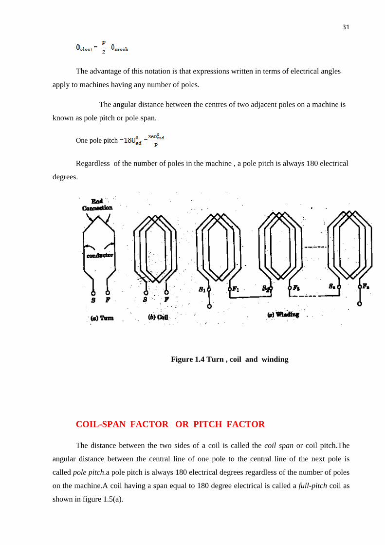
A TURN consists of two conductors connected to one end by an end connector.
A coil is formed by connecting several turns in series .
The turn ,Coil and windings are shown schematically in figure 1.4.
The beginning of the turn, or coil, is identified by the symbol S(Start) and the end of
the turn or coil by the symbol F(Finish).
The concept of electrical degrees is very useful in the study of machine. If
mechanical degrees or angular measure in space
= electrical degrees or angular measure in cycles
For a P-pole machine electrical degree is defined as follows:
31
Contd…
=
The advantage of this notation is that expressions written in terms of electrical angles
apply to machines having any number of poles.
The angular distance between the centres of two adjacent poles on a machine is
known as pole pitch or pole span.
One pole pitch = =
Regardless of the number of poles in the machine , a pole pitch is always 180 electrical
degrees.
Figure 1.4 Turn , coil and winding
COIL-SPAN FACTOR OR PITCH FACTOR
The distance between the two sides of a coil is called the coil span or coil pitch.The
angular distance between the central line of one pole to the central line of the next pole is
called pole pitch.a pole pitch is always 180 electrical degrees regardless of the number of poles
on the machine.A coil having a span equal to 180 degree electrical is called a full-pitch coil as
shown in figure 1.5(a).

32
Contd…
A coil having a span less than 180 electrical degrees is called a short-pitch coil or
fractional pitch coil.It is also called a chorded coil.A stator winding using fractional-pitch coils
is called a chorded winding.If the span of the coil is reduced by an angle of elctrical
degrees,the coil span will be (180- ) electrical degrees as shown in figure 1.6(a).
In case of full-pitch coil two coil sides span a distance exactly equal to the pole pitch of
180 electrical degrees .As a result, the voltage generated in a full-pitch coil is such that the coil
side voltages are in phase as shown in figure 1.5(b).Let be the voltages generated in
the coil sides and the resultant coil voltage. Then
+
Let |Ec1|=|Ec2|=E1
Since & are in phase,the resultant coil voltage is equal to their arithmetic sum.
+ = 2
Fig. 1.5 Fig. 1.6

33
Contd…
If the coil span of a single coil is less than the pole pitch of (elec.), the voltage
generated in each coil side are not in phase.The resultant coil voltage is equal to the phasor
sum of .
If the coil span is reduced by an angle elctrical degrees,the coil span is be (180- )
electrical degrees.The voltage generated in two coil sides will be out of phase w.r.t
each other by an angle the phasor sum of
is (=AC).
The coil span factor or pitch factor is defined as the ratio of voltage generated in
the short-pitch coil to the voltage generated in the full-pitch coil. The coil span factor is also
called the chording factor.
=
= = = cos
= cos ……………………………………………………….. 1.12
For full-pitch coil, =0, so, cos =1 and =1.For a short-pitch coil < 1.
Advantages of short pitching or chording
1. Shortens the ends of the winding and therefore there is aa saving in the conductor
material.
2. Reduces the effects of distorting harmonics, and thus the wave form of the
generated voltage is improved and making it approach a sine wave.
DISTRIBUTION FACTOR OR BREADTH FACTOR
In a concentrated winding ,the coil sides of a given phase are concentrated in a single
slot under a given pole. The individual coil voltages induced are in phase with each
other.These voltages may be added arithmetically. In order to determine the induced voltages

34
Contd…
induced per phase, a given coil voltage is multiplied by the number of series –connected coils
per phase. In actual practice, in each phase, coils are not concentrated in a single slot, but are
distributed in a number of slots in space to form a polar group under each pole. The voltages
induced in coil-sides constituting a polar group are not in phase but differ by an angle equal to the
angular displacement of the slots.The total voltage induced in any phase will be the phasor sum of
the individual coil voltages.
The distribution factor or breadth factor is defined as the ratio of the actual voltage
obtained to the possible voltage if all the coils of a polar group were concentrated in a single
slot.
= ……………….1.13
Let m = the slots per pole per phase ,that is slots per phase belt
m = …………………………………..1.14
= Angular displacement between adjacent slots in electrical degrees
= …………………………………..1.15
Fig.`1.7

35
Contd…
Thus, one phase of the winding consists of coils arranged in m consecutive slots.
Voltage , & ,…….. are the individual coil voltages .Each coil voltage will be
out of phase with the next coil voltage by the slot pitch .Figure 1.7 shows the voltage
polygon of the induced voltages in the four coils of a group(m=4).The voltages , , ,
and are represented by phasors AB,BC,CD and DF respectively in figure 1.7.Each of these
phasors is a chord of a circle with center o and subtends an angle at O.The phasor sum AF,
representing the resultant winding voltage ,subtends an angle m at the center.
Arithmatic sum of individual coil voltages
= m =m AB=m (2AM)
=2m sin Aom = 2m OA sin
= =
= …………………………………..1.16
It is to be noted that the distribution factor for a given number of phases is dependent only
on the number of distributed slots under a given pole.It is independent of the type of the winding,Lap or
wave,or the number of coil,etc. As the number of slots per pole increases the distribution factor
decreases.
ACTUAL VOLTAGE GENERATED
Taking the oil span factor and the distribution factor into acount ,the actual generated voltage
per phase is given by Ep =4.44 fФ
…………………………………………………………….. 1.17
Equation (1.17) is called the complete emf equation of an alternator.
The quantity ) is sometimes called effective turns per phase .
= …………………………………..1.18
36
Contd…
It ia smaller than the actual number of turns per phase due to fractional pitch coils and due to
distribution of winding over several slots under each pole.
The coil span factor and distribution factor of a winding are sometimes combined into a
single winding factor which is the product of . That is
= …………………………………..1.19
For a star connected alternator , the line voltage is times the phase voltage .
Alternative terms for the voltage E are
Open circuit voltage per phase
No-Load voltage per phase
Excitation voltage per phase
Internal voltage per phase
Voltage behind synchronous reactance per phase
The angle between the terminal voltage V and the internal voltage E is the machine
angle or rotor angle .
Example 1.2
A 3-phase , 50 Hz , 8-pole alternator has a star-connected winding with 120 slots and
8 conductors per slot.The flux per pole is 0.05 Wb, sinusoidally distributed.Determine the
phase and line voltages.
Solution :
Let us take the full-pitch coil,
So, = , = = = 1
m = = = 50 Hz
37
Contd…
= = =12
Kd= = = 0.9567
Total number of conductors = conductors per slot X number of slots = 8 x 120 = 960
Conductors per phase = , = = 320
Generated voltage per phase = = 2.22 fФ
= 2.22 x1 x 0.9567 x 50 x 0.05 x 320 = 1699 volts
Generated Line voltage = = = 2942.8 volts.
ARMATURE LEAKAGE REACTANCE
In a n ac machine ,any flux set up by the load current which does not contribute to the
usuful flux of the machine is a leakage flux. The effect of this leakage flux is to set up a self-
induced emf in the armature windings.
The leakage fluxes may be classified as follows :
1. Slot leakage
2. Tooth head leakage
3. Coil-end or over-hang leakage
The voltages induced in the armature windings by the air-gap flux is called the air-gap
voltages.
The leakage fluxes also induce voltages in the armature windings .These are taken into
account by introduction of leakage reactance drops. Most of the reluctances of the magnetic
circuits for armature leakage fluxes are due to air paths. The fluxes are therefore nearly
proportional to the armature currents producing them and are in phase with these currents. For
this reason, the voltages they induce in the armature windings can be taken into account by the
use of constant leakage reactances for the phases, which multiplied by the phase currents ,
give the component voltages induced in the phases of the leakage flux. These voltages are the
leakage reactance drops and lead the currents producing them by .
38
Contd…
ARMATURE REACTION
When load current flows through the armature windings of an alternator, the resulting
mmf produces flux. This armature flux reacts with the main-pole flux, causing the resultant
flux to become either less than or more than the original main flux. The effect of the
armature(stator) flux on the flux produced by the rotor field poles is called armature
reaction. The armature reaction flux is constant in magnitude and rotates at synchronous
speed. The armature reaction depends upon the power factor of the load. If the armature
reaction flux is assumed to act independently of the main field flux, it induces a voltage in each
phase which lag the respective phase currents by . It is to be noted that armature reaction
effects are seen to be an essential part of the torque producing mechanism.
Two things are worth noting about the armature reaction in an alternator. First,the
armature flux and the flux produced by rotor ampere-turns rotate at the same speed
(synchronous speed) in the same direction and,therefore,the two fluxex are fixed in space
relative to each other.Secondly,the modification of flux in the air-gap due to armature flux
depends on the magnitude of stator current and on the power factor of the load.It is the load
power factor which determines whether the armature flux distorts,opposes or helps the flux
produced by rotor ampere-turns.To illustrate this important point,the following three cases may
be considered :
(i) When load p.f. is unity
(ii) When load p.f. is zero lagging
(iii) When load p.f. is zero leading
When load p.f. is unity : Figure 1.7.1(i) shows an elementary alternator on no-
load.since the armature is on open-circuit, there is no stator current in the flux due to rotor
current is distributed symmetrically in the air-gap as shown in fig.1.7.1(i).Since the direction of
the rotor is assumed clockwise, the generated e.m.f in phase is at its maximum and is
towards the paper in the conductor and outwards in conductor . No armature flux is
produced since no current flows in the armature winding.
39
Contd…
Fig.1.7.1
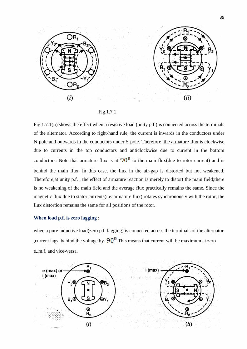
Fig.1.7.1(ii) shows the effect when a resistive load (unity p.f.) is connected across the terminals
of the alternator. According to right-hand rule, the current is inwards in the conductors under
N-pole and outwards in the conductors under S-pole. Therefore ,the armature flux is clockwise
due to currents in the top conductors and anticlockwise due to current in the bottom
conductors. Note that armature flux is at to the main flux(due to rotor current) and is
behind the main flux. In this case, the flux in the air-gap is distorted but not weakened.
Therefore,at unity p.f. , the effect of armature reaction is merely to distort the main field;there
is no weakening of the main field and the average flux practically remains the same. Since the
magnetic flux due to stator currents(i.e. armature flux) rotates synchronously with the rotor, the
flux distortion remains the same for all positions of the rotor.
When load p.f. is zero lagging :
when a pure inductive load(zero p.f. lagging) is connected across the terminals of the alternator
,current lags behind the voltage by .This means that current will be maximum at zero
e..m.f. and vice-versa.
40
Contd…
Fig.1.7.2
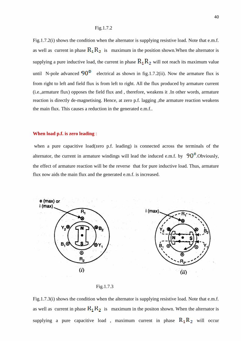
Fig.1.7.2(i) shows the condition when the alternator is supplying resistive load. Note that e.m.f.
as well as current in phase is maximum in the position shown.When the alternator is
supplying a pure inductive load, the current in phase will not reach its maximum value
until N-pole advanced electrical as shown in fig.1.7.2(ii). Now the armature flux is
from right to left and field flux is from left to right. All the flux produced by armature current
(i.e.,armature flux) opposes the field flux and , therefore, weakens it .In other words, armature
reaction is directly de-magnetising. Hence, at zero p.f. lagging ,the armature reaction weakens
the main flux. This causes a reduction in the generated e.m.f..
When load p.f. is zero leading :
when a pure capacitive load(zero p.f. leading) is connected across the terminals of the
alternator, the current in armature windings will lead the induced e.m.f. by .Obviously,
the effect of armature reaction will be the reverse that for pure inductive load. Thus, armature
flux now aids the main flux and the generated e.m.f. is increased.
Fig.1.7.3
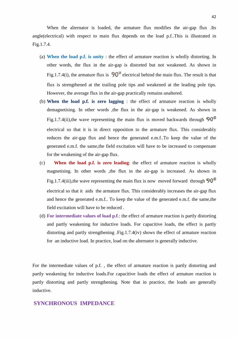
Fig.1.7.3(i) shows the condition when the alternator is supplying resistive load. Note that e.m.f.
as well as current in phase is maximum in the positon shown. When the alternator is
supplying a pure capacitive load , maximum current in phase will occur

41
Contd…
before the occurrence of maximum induced e.m.f.Therefore,maximum
current in phase will occur if the position of the rotor remains behind as
compared to its position under resistive load. This is illustrated in fig.1.7.3(ii).It is clear that
armature flux is now in the same direction as the field flux and therefore, strengthens it. This
causes an increase in the generated voltage. Hence at zero p.f. leading ,the armature reaction
strengthens the main flux.
For intermediate values of p.f., the effect of armature reaction is partly distorting and partly
weakening for inductive loads. For capacitive loads, the effect of armature reaction is partly
distorting and partly strengthening. Note that in practice, loads are generally inductive.
Summary :
Fig.1.7.4
42
Contd…
When the alternator is loaded, the armature flux modifies the air-gap flux .Its
angle(electrical) with respect to main flux depends on the load p.f..This is illustrated in
Fig.1.7.4.
(a) When the load p.f. is unity : the effect of armature reaction is wholly distorting. In
other words, the flux in the air-gap is distorted but not weakened. As shown in
Fig.1.7.4(i), the armature flux is electrical behind the main flux. The result is that
flux is strengthened at the trailing pole tips and weakened at the leading pole tips.
However, the average flux in the air-gap practically remains unaltered.
(b) When the load p.f. is zero lagging : the effect of armature reaction is wholly
demagnetising. In other words ,the flux in the air-gap is weakened. As shown in
Fig.1.7.4(ii),the wave representing the main flux is moved backwards through
electrical so that it is in direct opposition to the armature flux. This considerably
reduces the air-gap flux and hence the generated e.m.f..To keep the value of the
generated e.m.f. the same,the field excitation will have to be increased to compensate
for the weakening of the air-gap flux.
(c) When the load p.f. is zero leading: the effect of armature reaction is wholly
magnetising. In other words ,the flux in the air-gap is increased. As shown in
Fig.1.7.4(iii),the wave representing the main flux is now moved forward through
electrical so that it aids the armature flux. This considerably increases the air-gap flux
and hence the generated e.m.f.. To keep the value of the generated e.m.f. the same,the
field excitation will have to be reduced .
(d) For intermediate values of load p.f.: the effect of armature reaction is partly distorting
and partly weakening for inductive loads. For capacitive loads, the effect is partly
distorting and partly strengthening .Fig.1.7.4(iv) shows the effect of armature reaction
for an inductive load. In practice, load on the alternator is generally inductive.
For the intermediate values of p.f. , the effect of armature reaction is partly distorting and
partly weakening for inductive loads.For capacitive loads the effect of armature reaction is
partly distorting and partly strengthening. Note that in practice, the loads are generally
inductive.
SYNCHRONOUS IMPEDANCE

43
Contd…
The actual generated voltage consists of the summation of two component voltages. One of
these component voltages is the voltage that would be generated if there were no armature
reaction. It is the voltage that would be generated because of only the field excitation. This
component of the generated voltage is called the excitation voltage, .
The other component of the generated voltage is called the armature reaction voltage, .
This is the voltage that must be added to the excitation voltage to take care of the effect of
armature reaction upon the generated voltage
…………………………………..1.20
Since armature reaction results, in a voltage effect in a circuit caused by change in flux by
current in the same circuit ,its effect is of the nature of an inductive reactance .Therefore,
is equivalent to a voltage of inductive reactance and
= -j …………………………………..1.21
The inductive reactance is a ficticitous reactance which will result in a voltage in the
armature circuit to account for the effect of armature reaction upon the voltage relations of the
armature circuit. Therefore, armature reaction voltage can be modeled as an inductor in series
with the internal generated voltage.
In addition to the effects of armature reaction, the stator winding also has a self-inductance
and a resistance.
Let = Self-inductance of stator winding
= Self-inductive reactance of stator winding
=Armature (stator) resistance
The terminal voltage V is given by
V = -j -j -
Where = armature resistance drop
= armature leakage reactance drop
= armature reaction voltage
44
Contd…
The armature reaction effects and the leakage flux effects in the machine are both represented
by inductive reactances . Therefore, it is customary to combine them in to a single reactance,
called the synchronous reactance of the machine, .
…………………………………..1.22
V= - j -
Or V= - …………………………………..1.23
V= - …………………………………..1.24
Where = …………………………………..1.25
The impedance is called the synchronous impedance.
The synchronous reactance is the ficticious reactance employed to account for the
voltage effects in the armature circuit produced by the actual armature leakage reactance and
by the change in air-gap flux caused by the armature reaction.
Similarly,the synchronous impedance is a ficticious impedance employed to
account for the voltage effects in the armature circuit produced by the actual armature
resistance,the actual armature leakage reactance and the change in air-gap flux caused by the
armature reaction.
EQUIVALENT CIRCUIT AND PHASOR DIAGRAMS OF A SYNCHRONOUS
GENERATOR
The equivalent reactance of a synchronous generator is shown in figure 1.8(a). It is redrawn in
Fig.1.8(b) by taking

45
Contd…
Fig.1.8 Equivalent circuit of a synchronous generator
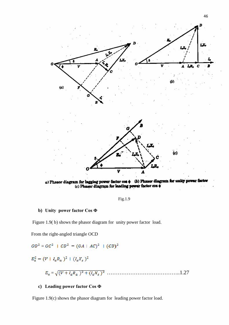
a) Lagging power factor Cos Φ
Figure 1.9(a) shows the phasor diagram for lagging p.f. load. The power factor is Cos
Ф lagging.In this diagram the terminal voltage V is taken as reference phasor along OA such
that OA =V. For lagging power factor Cos Ф, the direction of armature current lags behind
the voltage V by an angle Ф along OB ,where OB = .The voltage drop in the armature
resistance is .It is represented by phasor AC.The voltage drop in the synchronous
reactance is .It is represented by CD .It leads the current by and, therefore,CD is
drawn in a direction perpendicular to OB. The total voltage drop in the synchronous
impedance is the phasor sum of .It is represented by AD.The phasor OD
represents .
The magnitude can be found from the right-angled triangle OGD
=
=
…………………………………..1.26
46
Contd…
Fig.1.9
b) Unity power factor Cos Φ
Figure 1.9( b) shows the phasor diagram for unity power factor load.
From the right-angled triangle OCD
=
= …………………………………..1.27
c) Leading power factor Cos Φ
Figure 1.9(c) shows the phasor diagram for leading power factor load.
47
Contd…
From the right-angled triangle OGD
=
=
…………………………………..1.28
The angle δ between & V is called the power angle or Torque angle of the
machine. It varies with load and is a measure of air-gap power developed in the machine.
VOLTAGE REGULATION
The voltage regulation of as synchronous generator is defined as the change in terminal voltage
from no-load to full-load divided by the full-load voltage when the speed and field current remaining
constant.
It is expressed as a fraction or a percentage of full-load terminal voltage .It can be written as
Per unit voltage regulation =
Percentage voltage regulation == = x 100
Where = magnitude of generated voltage per phase
V = magnitude of rated terminal voltage per phase
The voltage regulation depends upon the power factor of the load. For unity and
lagging power factors, there is always a voltage drop with the increase of load, but for a
certain leading p.f. the full-load regulation is zero. In this case the terminal voltage is same for
both full-load and no-load conditions. At lower leading power factors the voltage rises with the
increase of load,and the regulation is negative.
DETERMINATION OF VOLTAGE REGULATION
The KVA ratings of commercial alternators are very high(.Example 500MVA). It is
neither convenient nor practicable to determine the voltage regulation by direct loading. There
are several indirect methods of determining the voltage regulation of an alternator. These

48
Contd…
methods require only a small amount of power as compared to the power required for a direct
loading method.
Three such methods are
(i) Synchronous impedance method
(ii) Ampere-Turn method
(iii) Zero power factor or Potier method
For the synchronous impedance method the following tests are conducted .
MEASUREMENT OF SYNCHRONOUS IMPEDANCE
The following tests are performed on an alternator to know itsb performance.
a) DC resistance test
b) Open-circuit test
c) Short-circuit Test
DC RESISTANCE TEST
Assume that the alternator is star connected with d.c. field winding open(Fig. 1.10) ,
measure the d.c. resistance between each pair of terminals either by using ammeter-voltmeter
method or by using Wheat stone’s bridge. The average of three sets of resistance values is
taken. This value of is divided by 2 to get the d.c. resistance(ohmic resistance) per
phase.The alternator should be at rest. Since the effective a.c. resistance is larger than d.c.
resistance due to skin effect, therefore, effective a.c. resistance per phase is obtained by
multiplying the d.c. resistance by a factor of 1.2 to 1.75 depending on the size of the machine.
Fig.1.10 D.C. resistance test on an alternator.
Open –circuit Test

49
Contd…
The alternator is run at rated synchronous speed and the load terminals are kept open
Fig.1.11. That is, all the loads are disconnected .The field current is set to zero.
Fig.1.11 Open-circuit test on an alternator.
Then the field current is gradually increased in steps, and the terminal voltage is
measured at each step.The excitation current may be increased to get 25% more than rated
voltage of the alternator.A graph is plotted between the open-circuit. phase voltage
(= / ) and field current .The characteristics curve so obtained is called open-circuit
characteristics(O.C.C.).It takes the shape of a normal magnetization curve.The extension of the
linear portion of an O.C.C is called the air-gap line of the characteristics. The O.C.C. and the
air-gap line are shown in figure 1.12.
Fig.1.12 The O.C.C. of an alternator

50
Contd…
Short-Circuit Test
The armature terminals are shorted through three ammeters (Fig. 1.13) . Care should be
taken in performing this test, and the field current should first be decreased to zero before
starting the alternator. Each ammeter should have a range greater than the rated full-load value.
The alternator is then run at synchronous speed. Then the field current is gradually increased in
steps , and the armature current is measured at each step. The field current may be increased to
get armature currents upto 150% of the rated value. The field current and the average of
three ammeter readings at each step is taken. A graph is plotted between the armature current and
the field current .The characteristics so obtained is called short-circuit characteristics (SCC).This
characteristic is a straight line as shown in figure 1.14.
Fig.1.13
Fig.1.14.The S.C.C of an alternator
51
Contd…
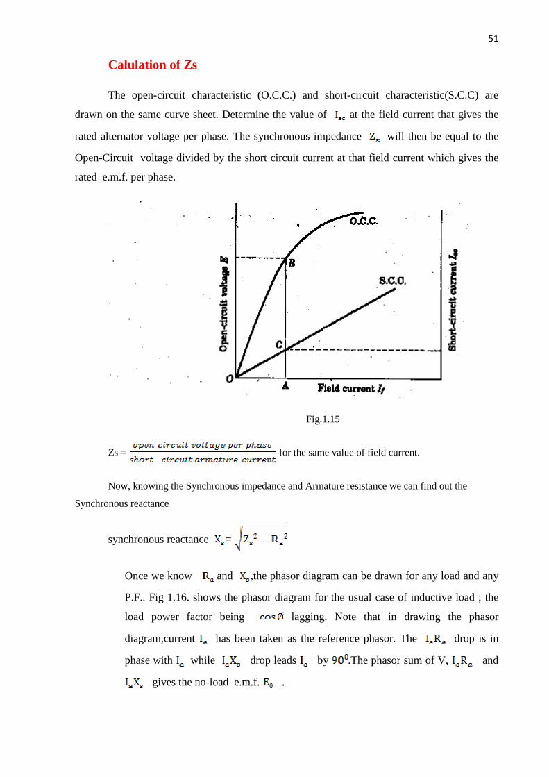
Calulation of Zs
The open-circuit characteristic (O.C.C.) and short-circuit characteristic(S.C.C) are
drawn on the same curve sheet. Determine the value of at the field current that gives the
rated alternator voltage per phase. The synchronous impedance will then be equal to the
Open-Circuit voltage divided by the short circuit current at that field current which gives the
rated e.m.f. per phase.
Fig.1.15
Zs = for the same value of field current.
Now, knowing the Synchronous impedance and Armature resistance we can find out the
Synchronous reactance
synchronous reactance =
Once we know and ,the phasor diagram can be drawn for any load and any
P.F.. Fig 1.16. shows the phasor diagram for the usual case of inductive load ; the
load power factor being lagging. Note that in drawing the phasor
diagram,current has been taken as the reference phasor. The drop is in
phase with while drop leads by .The phasor sum of V, and
gives the no-load e.m.f. .

52
Contd…
.
Fig.1.16
Now,
=
= V + and = V +
=
voltage regulation = 100
Drawback : This method is easy but it gives approximate results .The reason is
simple. The combined effect of (armature leakage reactance) and (reactance of armature
reaction ) is measured on short-circuit.Since the current in this condition is almost lagging
,the armature reaction will provide its worst demagnetizing effect. It follows that under any
normal operation at,say 0.8 or 0.9 lagging power factors will produce error in calculations.
This method gives a value higher than the value obtained from an actual load test.For this
reason, it is called pessimistic method.
53
Contd…
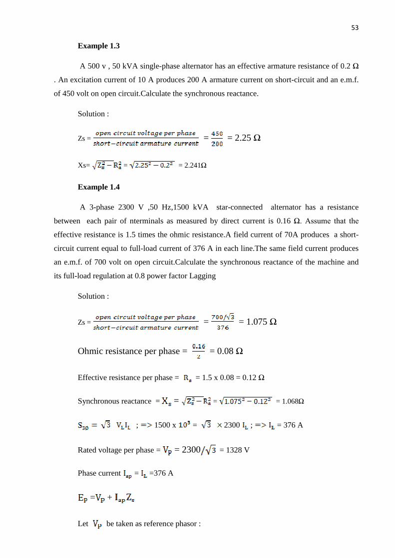
Example 1.3
A 500 v , 50 kVA single-phase alternator has an effective armature resistance of 0.2 Ω
. An excitation current of 10 A produces 200 A armature current on short-circuit and an e.m.f.
of 450 volt on open circuit.Calculate the synchronous reactance.
Solution :
Zs = = = 2.25 Ω
Xs= = = 2.241Ω
Example 1.4
A 3-phase 2300 V ,50 Hz,1500 kVA star-connected alternator has a resistance
between each pair of nterminals as measured by direct current is 0.16 Ω. Assume that the
effective resistance is 1.5 times the ohmic resistance.A field current of 70A produces a short-
circuit current equal to full-load current of 376 A in each line.The same field current produces
an e.m.f. of 700 volt on open circuit.Calculate the synchronous reactance of the machine and
its full-load regulation at 0.8 power factor Lagging
Solution :
Zs = = = 1.075 Ω
Ohmic resistance per phase = = 0.08 Ω
Effective resistance per phase = = 1.5 x 0.08 = 0.12 Ω
Synchronous reactance = = = = 1.068Ω
; 1500 x = 2300 ; = 376 A
Rated voltage per phase = = 2300 = 1328 V
Phase current = =376 A
= +
Let be taken as reference phasor :

54
Contd…
= L = 1328 L volts =1328 + j 0 volts
= L =376 L- A
= + = 0.12+j 1.068 =1.075L8 Ω
= 1328 + j 0 +(376 L- )( 1.075L8 ) = 1328+404.2L
= 1328+277.1+j 294.26 = 1605.1+j 294.26 =1631L volt
Percentage Regulation = x 100 = 22.8
AMPERE-TURN METHOD
This method of finding voltage regulation considers the opposite view to the synchronous
impedance method. It assumes the armature leakage reactance to be additional armature
reaction. Neglecting armature resistance(always small),this method assumes that change in
terminal p.d. on load is due entirely to armature reaction. The same two tests(Open and short
circuit test)are required as for synchronous reactance determination ; the interpretation of the
results only is different. Under short-circuit, the current lags by ( considered zero) and
the power factor is zero.Hence,the armature reaction is entirely demagnetizing. Since,the
terminal p.d. is zero,all the field AT(ampere-turns)are neutralized by armature AT produced by
the short circuit armature current.
(i) Suppose the alternator is supplying full-load current at normal voltage V(i.e.,operating
load voltage)and zero p.f. lagging. Then d.c. field AT required will be those needed
to produce normal voltage V(or if is to be taken into account,then V+
) on no-load plus those to overcome the armature reaction.
Let AO =field AT required to produce the normal voltage V (or V+ ) at
no-load.
O =field AT required to neutralize the armature reaction
Then total field AT required are the phasor sum of AO+O (Fig.1.17(i))
total field AT, A = AO+O ………phasor sum

55
Contd…
The AO can be found from O.C.C. and O can be determined from S.C.C.. Note
that the use of a d.c. quantity(field AT)as a phasor is perfectly valid in this case
because the d.c. field is rotating at the same speed as the a.c. phasors i.e. .
Fig 1.17
(ii) For a full-load current of zero p.f. leading, the armature AT are unchanged. Since they
aid the main field, less field AT are required to produce the given e.m.f.
So, the total field AT, A = AO- ……………………………phasor difference
Where =field AT required to neutralize armature reaction
This is illustrated in Fig 1.17(ii).Note that again AO is determined from O.C.C. and
from S.C.C.
(iii)Between zero lagging and zero leading power factors,the armature m.m.f. rotates
through . At unity p.f. ,armature reaction is cross-magnetising only.Therefore,
O is drawn perpendicular to AO(Fig.1.17(iii)).Now A shows the required AT
in magnitude and direction.
General Case .
It may now be discussed the case when the pf has any value between zero (lagging
or leading) and inity.If the power-factor is lagging,then is laid off to the
right of the vertical line O as shown in Fig.1.18(i).The total field AT required are
A i.e.,phasor sum of AO and O .If the power factor is leading , then is
laid off to the left of the vertical line O as shown in Fig.1.18(ii).The total field
AT required are A i.e.,phasor sum of AO and O .

56
Contd…
Fig 1.18
Since current AT , it is more convenient to work in terms of field current.Fig. 1.19 shows
the current diagram for the usual case fo lagging power factor.Here AO represents the field
current required to produce normal voltage V (or ) on no-load. The phasor
OB represents the field current required for producing full-load current on short –circuit.The
resultant field current is AB and the phasor sum of AO and OB.Note thatphasor AB represents
the field current required for demagnetizing an dto produce voltage V and drop.(if
is taken into account).
Fig.1.19
PROCEDURE FOR AT METHOD
Suppose the alternator is supplying full-load current at operating voltage Vand p.f.
lagging.The procedure for finding voltage regulation for AT method is as under :
(i) From the O.C.C.,field current OA required to produce the operating load voltage V(or
) is determined as shown in Fig.1.20.The field current OA is alid
off horizontally as shown in Fig.1.21.

57
Contd…
Fig.1.20 Fig.1.21
(ii) From S.C.C.,the field current OC required for producing full-load current on short-
circuit is determined.The phasor AB(=OC) is drawn at an angle of (
i.e.,Arg(OAB = as shown in Fig. 1.21.
(iii)The phasor sum of OA and AB gives the total field current OB required.The O.C.
voltage corresponding to field current OB on O.C.C. is the no-load e.m.f.
voltage regulation = 100
This method gives a regulation lower than the actual performance of the
machine.For this reason,it is known as Optimistic method.
ZERO POWER FACTOR METHOD OR POTIER METHOD
In this method, we separately determine the voltage drop due to armature leakage
reactance(= ) and voltage drop due to armature reaction(= ).Therefore, it gives more
accurate results. The Potier method consists of the following steps:
(i) Plotting O.C.C. :
The open-circuit characteristics (O.C.C.) of the alternator is plotted by conducting no-load test
on the alternator as explained earlier .The lower part of O.C.C. is practically a straight line and
when extended becomes the air-gap line. Therefore, air-gap line represents O.C.C. of the
alternator if the reluctance of the iron portion of the magnetic circuit of the machine is
neglected as compared to the reluctance of the air-gap.

58
Contd…
Fig.1.22
(ii) Plotting zero p.f. (lagging) full-load curve :
This is the curve between the terminal voltage and field current when the alternator is
delivering its full rated current to a zero power factor(lagging) load. The test is carried out by
running the alternator at synchronous speed and connecting a purely inductive 3-phase load to
its terminals. The load is varied in steps and at each step, the field current is adjusted so that
the armature current is equal to its rated value. There is no need to plot the full curve. Only two
points S &C (see fig.1.22) are sufficient. The point S corresponds to a field current which
gives the rated terminal voltage while the zero p.f. load is adjusted to draw the rated armature
current. The point C corresponds to the short-circuit conditions on the alternator(i.e. terminal
voltage =0) with the field current adjusted to give rated armature current. Since the armature
resistance is negligible, the short-circuit current lags behind the resultant induced e.m.f. by
.Therefore,point C constitutes a point on the zero p.f. curve.
(iii) Costructing potier triangle :
Referring to Fig. 1.22 OC is field current producing full-load armature current on
short-circuit(the current lags by ). Therefore, the field current OC must be sufficient to
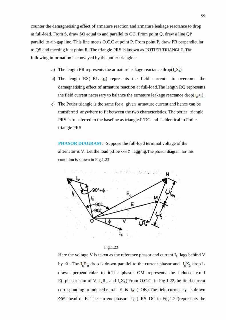
59
Contd…
counter the demagnetising effect of armature reaction and armature leakage reactance to drop
at full-load. From S, draw SQ equal to and parallel to OC. From point Q, draw a line QP
parallel to air-gap line. This line meets O.C.C at point P. From point P, draw PR perpendicular
to QS and meeting it at point R. The triangle PRS is known as POTIER TRIANGLE. The
following information is conveyed by the potier triangle :
a) The length PR represents the armature leakage reactance drop( ).
b) The length RS(=KL= ) represents the field current to overcome the
demagnetising effect of armature reaction at full-load.The length RQ represents
the field current necessary to balance the armature leakage reactance drop( ).
c) The Potier triangle is the same for a given armature current and hence can be
transferred anywhere to fit between the two characteristics. The potier triangle
PRS is transferred to the baseline as triangle P’DC and is identical to Potier
triangle PRS.
PHASOR DIAGRAM : Suppose the full-load terminal voltage of the
alternator is V. Let the load p.f.be lagging.The phasor diagram for this
condition is shown in Fig.1.23
Fig.1.23
Here the voltage V is taken as the reference phasor and current lags behind V
by . The drop is drawn parallel to the current phasor and drop is
drawn perpendicular to it.The phasor OM represents the induced e.m.f
E(=phasor sum of V, and ).From O.C.C. in Fig.1.22,the field current
corresponding to induced e.m.f. E is (=OK).The field current is drawn
ahead of E. The current phasor (=RS=DC in Fig.1.22)represents the

60
Contd…
field current necessary to overcome the demagnetising effect of armature
reaction at full-load and is drawn parallel to the current phasor .The phasor
sumof & gives the total field current required to produce .The
phasor (=ON) lags behind by .Note that phasor MN represents the
voltage drop due to armature reaction.
Percentage voltage regulation = x 100
PROCEDURE FOR POTIER METHOD
For solving problems relating to Potier method, the following procedure is adopted:
(i) Suppose the terminal voltage per phase is V.
(ii) Find the armature leakage reactance drop( ) from the potier
triangle.
(iii) Add )(and if given) vectorially to V to get E.
(iv) From the O.C.C, find the field current required to produce E. Let it be
.
(v) From the potier triangle, find the field current necessary for balancing
armature reaction. Let it be .
(vi) Find the phasor sum of to get the resultant field current .
(vii) From the O.C.C. , find the e.m.f. corresponding to field current . This
gives us .Therefore, we can find the voltage regulation.
LIMITATIONS OF POTIER METHOD
The Potier method has the following drawbacks :
(a) The Potier triangle is based on the assumption that the armature leakage
reactance is constant and the O.C.C. of the alternator is the same under load as it
is under open-circuit conditions. However ,this is not correct. Therefore, the
value of armature leakage reactance determined by the potier triangle method is
not absolutely accurate. In order to distinguish the value of leakage reactance
thus determined from the absolutely correct value, the value of leakage
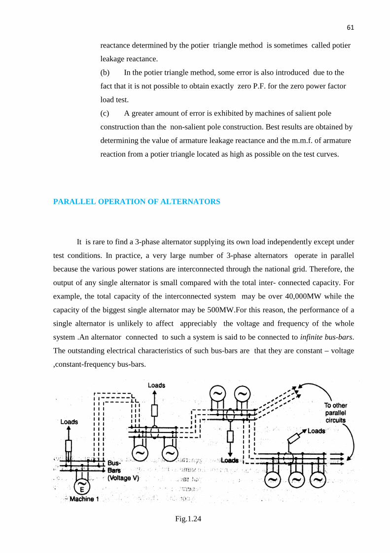
61
Contd…
reactance determined by the potier triangle method is sometimes called potier
leakage reactance.
(b) In the potier triangle method, some error is also introduced due to the
fact that it is not possible to obtain exactly zero P.F. for the zero power factor
load test.
(c) A greater amount of error is exhibited by machines of salient pole
construction than the non-salient pole construction. Best results are obtained by
determining the value of armature leakage reactance and the m.m.f. of armature
reaction from a potier triangle located as high as possible on the test curves.
PARALLEL OPERATION OF ALTERNATORS
It is rare to find a 3-phase alternator supplying its own load independently except under
test conditions. In practice, a very large number of 3-phase alternators operate in parallel
because the various power stations are interconnected through the national grid. Therefore, the
output of any single alternator is small compared with the total inter- connected capacity. For
example, the total capacity of the interconnected system may be over 40,000MW while the
capacity of the biggest single alternator may be 500MW.For this reason, the performance of a
single alternator is unlikely to affect appreciably the voltage and frequency of the whole
system .An alternator connected to such a system is said to be connected to infinite bus-bars.
The outstanding electrical characteristics of such bus-bars are that they are constant – voltage
,constant-frequency bus-bars.
Fig.1.24
62
Contd…
Fig. 1.24 Shows a typical infinite bus system .Loads are tapped from the infinite bus at
various load centers. The alternators may be connected to or disconnected from the infinite
bus, depending on the power demand on the system. If an alternator is connected to infinite
bus-bars, no matter what power is delivered by the in-coming alternator, the voltage and the
frequency of the system remain the same. The operation of connecting an alternator to the
infinite bus-bars is known as parallel with the infinite bus-bars. It may be noted that before an
alternator is connected to an infinite bus-bars, certain conditions must be satisfied.
ADVANTAGES of PARALLEL OPERTIONS OF ALTERNATORS
The following are the advantages of operating alternators in parallel.
(i) Continuity of service : The continuity of service is one of the important requirements of
any electrical apparatus. If one alternator fails, the continuity of supply can be maintained
through the other healthy units. This will ensure un-interrupted supply to the consumers.
(ii)Efficiency :The load on the power system varies during the whole day ; being minimum
during the late night hours. Since, alternators operate most efficiently when delivering full-
load ,units can be added or put-off depending upon the load requirement. This permits the
efficient operation of power system.
(iii)Maintainance and Repair : It is often desirable to carry out routine maintenance and
repair of one or more units. For this purpose , the desired unit /units can be shut down and the
continuity of supply is maintained through the other units.
(iv)Load growth: The load demand is increasing due to the increase in use of electrical
energy. The load growth can be met by adding more units without disturbing the original
installation .
CONDITIONS FOR PARALLELING ALTERNATOR WITH INFINITE BUSBARS
The proper method of connecting an alternator to the infinite bus-bars is called synchronising.
A stationary alternator must not be connected to live bus-bars. It is because the induced e.m.f.
is zero at stand-still and a short-circuit will result .In order to connect an alternator safely to the
infinite bus-bars , the following conditions are met.
(i) The terminal voltage (r.m.s. value) of the incoming alternator
must be the same as bus-bars voltage.
(ii) The frequency of the generated voltage of the incoming
alternator must be equal to the bus-bars frequency.
63
Contd…
(iii) The phase of the incoming alternator voltage must be identical
with the phase of the bus-bars voltage. In other words, the two
voltages must be in-phase with each other.
(iv) The phase sequence of the voltage of the incoming alternator
should be same as that of the bus-bars.
The magnitude of the voltage of the incoming alternator can be adjusted by changing its field
excitation. The frequency of the incoming alternator can be changed by adjusting the speed of
the prime-mover driving the alternator.
Condition(i) is indicated by a voltmeter, condition (ii) & (ii) are indicated by synchronizing
lamps or a synchroscope. The condition (iv) is indicated by a phase sequence indicator.
METHODS OF SYNCHRONISATION
The method of connecting an incoming alternator safely to the live busbars is called
synchronising. The quality of voltage between the incoming alternators and the busbars can be
easily checked by a voltmeter. The phase sequence of the alternator and the busbars can be
checked by a phase sequence indicator. Differences in frequency and phase of the voltages of
the incoming alternators and busbars can be checked by one of the following two methods.
1. By three lamps(one dark,two bright) method.
2. By synchroscope
Three-Lamp method : In this method of synchronising ,three lamps are
connected as shown inFig1.25.The lamp is straight connected between the corresponding
phases ( ) and the other two are cross-connected between the other two phases. Thus,
lamp is connected between & and lamp between & .When the frequency
& phase of the voltage of the incoming alternator is the same as that of the busbars, the straight
connected lamp will be dark while cross-connected lamp will be equally bright.
At this instant ,the synchronisation is perfect and the switch of the incoming alternator can be
closed to connect it to the busbars. In Fig.1.25 Phasors , represent the busbar
voltages and phasors , & represent the voltages of the incoming alternator. At the
instant when is inphase with ,voltage across lamp is zero and voltages across lamps

64
Contd…
& are equal. Therefore ,lamp is dark while lamps & will be equally bright .At
this instant, the switch of the incoming alternator can be closed.Thus,incoming alternator gets
connected in parallel with the busbars.
Fig.1.25
Synchroscope : A synchroscope is an instrument that indicates by means of a revolving
pointer the phase difference and the frequency difference between the voltages of the
incoming alternator and the busbars(Fig. 1.26). It is essentially a small motor ,the field being
supplied from the busbars through a potential transformer and the rotor from the incoming
alternator. Pointer is attached to the rotor. When the incoming alternator is running fast
,(i.e.the frequency of the incoming alternator is higher than that of the busbars),the rotor and
hence pointer moves in the clock-wise direction. When the incoming alternator is running slow
that is ,(frequency of the incoming alternator is lower than that of the busbars),the pointer
moves in anti-clockwise direction.When the frequency of the incoming alternator is equal to
that of the busbars , no torque acts on the rotor and the pointer points vertically upwards (“12
O’ Clock”).It indicates the correct instant for connecting the incoming alternator to the
busbars. The synchroscope method is superior to the Lamp method because it not only gives a
positive indication of the time to close the switch but also indicates the adjustments to be made

65
Contd…
should there be a difference between the frequencies of the incoming alternator and the
busbars.
Fig.1.26
Synchronising action :
When two or more alternators have been connected in parallel ,they will remain in stable
operation under all normal conditions i.e., voltage ,frequency, speed and phase equality will
continue .In other words, once synchronised properly, the alternators will continue to run in
synchronism under all normal conditions. If one alternator tries to fall out of synchronism ,it is
immediately counteracted by the production of a synchronising torque which brings it back
to synchronism. This automatic action is called the synchronising action of the alternators.
Consider two similar single-phase alternators 1 &2 operating in parallel as shown in
Fig. 1.27 (i).For simplicity, let us assume that the alternators are at no-load. When in exact
synchronism , magnitudes of the small e.m.f. s (Machine 1) & (machine 2 ) are equal.
These e.m.f.s are acting in the same direction with respect to the external circuit as shown in
Fig.1.27(ii).But in relation to each other, these e.m.f.s are in phase opposition i.e. ,if we trace
the closed circuit formed by the two alternators we find that the e.m.f.s oppose each other as
shown in Fig 1.27(iii).When the alternators are in exact synchronism, & are in exact
phase opposition.Since, in magnitude, no current flows in the closed circuit formed
by the two alternators.
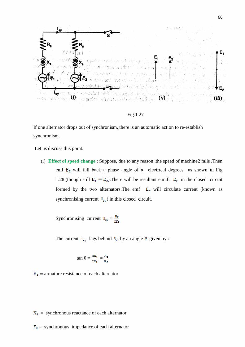
66
Contd…
Fig.1.27
If one alternator drops out of synchronism, there is an automatic action to re-establish
synchronism.
Let us discuss this point.
(i) Effect of speed change : Suppose, due to any reason ,the speed of machine2 falls .Then
emf will fall back a phase angle of α electrical degrees as shown in Fig
1.28.(though still ).There will be resultant e.m.f. in the closed circuit
formed by the two alternators.The emf will circulate current (known as
synchronising current ) in this closed circuit.
Synchronising current =
The current lags behind by an angle given by :
tan θ = =
armature resistance of each alternator
= synchronous reactance of each alternator
= synchronous impedance of each alternator

67
Contd…
Fig.1.28 Fig.1.29
Since, is very small as compared to , θ is nearly so that the current is almost
in phase with & in phase opposition to .This means that machine 1 is generating and
machine 2 is motoring . consequently, the machine 1 tends to slow down and machine 2, by
accepting power , tends to accelerate. This restores the status quo i.e., synchronism is re
established.
Conversely,if E2 tends to advance in phase,as shown in Fig.1.29 The directions of
and are changed such that now machine 2 is generating and machine 2 is motoring
.Once again the synchronism is restored.
(ii) Effect of inequality of e.m.f.s : The automatic re-establishment of synchronism of
two alternators operating in parallel also extends to any changes tending to alter the
individual e.m.f. s . When in exact synchronism ,then (magnitude) and they
are in exact phase opposition as shown in Fig.1.30(i). Suppose due to any reason ,
e.m.f. increases.Then resultant e.m.f. exists in the closed circuit formed by
the two alternators. Then = and is in-phase with .The resultant
e.m.f. sends synchronising current in the closed circuit.Here again the
current almost lags behind by (as Zs=Xs) as shown in Fig.1.30(ii).
Also lags almost behind and leads almost by .The power
produced is practically zero ; just enough to overcome copper losses. The current
lags behind and produces a demagnetising armature reaction effect on
machine1 .At the same time leads and produces magnetising armature
reaction effect on the machine2. Thus, tends to fall and tends to rise.The

68
Contd…
result is that synchronism is re-established . The converse is true for as
shown in Fig.1’30(iii)
Fig.1.30
SYNCHRONISING POWER :
When two alternators are operating in parallel, each machine has an inherent
tendency to remain synchronised . Consider two similar single-phase alternators 1
& 2 operating in parallel at no-load as shown in Fig . suppose ,due to any reason
,the speed of machine 2 decreases. This will cause to fall back by a phase angle
of α electrical degrees as shown in Fig.1.31(though still = ).Within the local
circuit formed by two alternators,the resultant e.m..f is the phasor difference
.This resultant e.m.f. results in the production of synchronising current
which sets up synchronising torque. The synchronising torque retards machine 1
and accelerates machine 2 so that synchronism is re-established.The power
associated with synchroniosing torque is called synchronizing power.
In Fig.1.32, machine 1 is generating and machine2 is motoring. The power supplied
by machine 1 is called synchronising power.

69
Contd…
Fig.1.31 Fig.1.32 Referring to Fig.1.32 we have, Synchronising power , = = =
= ( As θ = so that =1)
The synchronizing power goes to supply power input to machine 2 and the Cu losses in the local circuit of two machines. = + Cu losses
Resultant e.m.f. , =2E [ As
=2 E ) = 2 E = 2 E ( As α is small)
= αE
Note that in this expression, α is in electrical radians.
synchronising current = = ………………….. of both machines is
negligible
Here =synchronizing reactance of each machine
synchronizing power supplied by machine 1 is = = E =
Total synchronizing power for three phases =3 =
Note that this is the value of synchronizing power when two alternators operate in parallel at no-load.
……………………………..xxxxxxxxxxxxxxxxxxxxxxxx……………………………
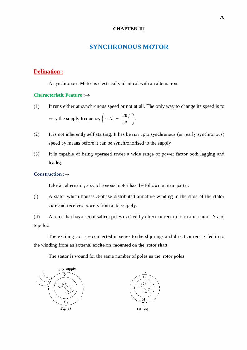
70
Contd…
CHAPTER-III
SYNCHRONOUS MOTOR
Defination :
A synchronous Motor is electrically identical with an alternation.
Characteristic Feature :®
(1) It runs either at synchronous speed or not at all. The only way to change its speed is to
very the supply frequency ÷øö
çèæ =
Pf
Ns120Q .
(2) It is not inherently self starting. It has be run upto synchronous (or rearly synchronous)
speed by means before it can be synchronorised to the supply
(3) It is capable of being operated under a wide range of power factor both lagging and
leadig.
Construction :®
Like an alternator, a synchronous motor has the following main parts :
(i) A stator which houses 3-phase distributed armature winding in the slots of the stator
core and receives powers from a 3f -supply.
(ii) A rotor that has a set of salient poles excited by direct current to form alternator N and
S poles.
The exciting coil are connected in series to the slip rings and direct current is fed in to
the winding from an external excite on mounted on the rotor shaft.
The stator is wound for the same number of poles as the rotor poles

71
Contd…
Principle of Operation :®
When a 3f winding is fed by a 3f supply then a magnetic field of constant magnitude
but rotating synchronous speed is produced in the stator. Consider a two pole stator which are
shown two stator pole Ns and Ss rotating at synchronous speed in clockwise direction.
With the rotor position as shown in fig. suppose the stator pole are at that instant
situated at point B. The two similar poles N and Ns as well as S and Ss will repel each other
with the result that the rotor tends to rotate on the anticlockwise direction.
But half a period later stator poles having rotate around interchange their position i.e.
Ns is at point B and Ss is at point A. Under these condition Ns atleast S and Ss attract N. Hence
rotor tends to rotate clockwise (which is just the reverse direction).
It is seen that due to continuous and rapid rotation the stator pole, te rotor is subjected a
torque which is rapidly revenging owing to this large inertial, the rotor cannot instantaneously
respond to such likely revenging torque with the result that it remains stationary.
Considering the condition in fig(b) the stator and rotor are alternating each other.
Suppose that the rotor is not stationary but is rotating clockwise with such a speed that it
rotates through one pole pitch by the times the stator poles interchanged their positions. As
shown in fig(c). Hence again stator and rotor poles attract each other. It means that if the rotor
pole also shift their position along with the stator poles, then they will produce a torque.
Method of starting :
The following steps are adopted for starting of a synchronous motor.
(1) The fed winding is shorted that means D.C. excitation is not given to the field winding.
(2) Reduced voltage with the help of auto-trans transformer is applied across the stator
terminal.
(3) When the motors at far nearly 9% of the synchronous speed, a d.c. excitation as applied to
the field winding. At that time the motor is synchronized.

72
Contd…
(4) full supply voltage is applied across stator terminals by cutting out the autotransformer .
(5) the motor then can be operated at any power factor by the d.c. excitation.
(6) At light load or heavy load condition the rotor advances and backs to the stator flux
respectively with an angle α. It is called the load angle.
Motor on no-load :
When a 3f supply is feed to a synchronous motor, the motor starts rotating. As a result
back emf (Es ) is set up in the alternator (stator) by the rotor flux which oppose the applied
voltage ‘V’ his back emf of (Es) depends on rotor excitation only (and not on peed) as in
D.C. motor. The net voltage of armature (stator in the voter difference of V & Eb Armature
current is obtained by dividing this vector difference of voltage by the armature impendance
i.e. S
EVI b
a
®®
-=
The Fig, show condition when the moor is running on no- direction on no-load & is
having loss. As field excitation is given such that Eb = V
The vector difference of Eb & V is f hence hence the armature current is also zero)
If the motor is on no load but it has losses then q vector for Eb faces back by a certain
angle ‘a’ . So that a resultant voltage ER & hence current ‘Ia is brought into existence which
supplies the losses.
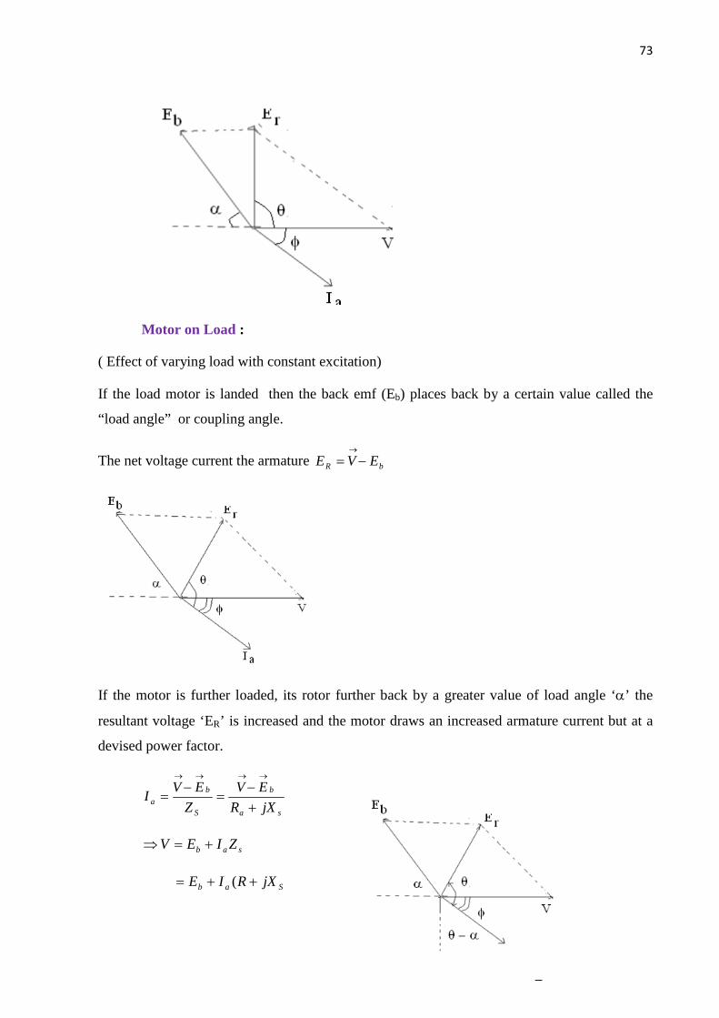
73
Contd…
Motor on Load :
( Effect of varying load with constant excitation)
If the load motor is landed then the back emf (Eb) places back by a certain value called the
“load angle” or coupling angle.
The net voltage current the armature bR EVE -=®
If the motor is further loaded, its rotor further back by a greater value of load angle ‘a’ the
resultant voltage ‘ER’ is increased and the motor draws an increased armature current but at a
devised power factor.
sa
b
S
ba jXR
EVZ
EVI
+-
=-
=
®®®®
sab ZIEV +=Þ
Sab jXRIE ++= (
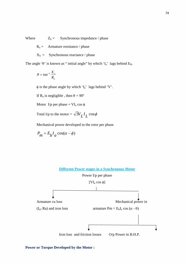
74
Contd…
Where ZS = Synchronous impedance / phase
Ra = Armature resistance / phase
XS = Synchronous reactance / phase
The angle ‘q’ is known as “ initial angle” by which ‘Ia’ lags behind ER.
a
s
RX1tan-=q
f is the phase angle by which ‘Ia’ lags behind ‘V’.
If Ra is negligible , then q = 90°
Motor I/p per phase = VIa cos f
Total I/p to the motor = fcos3 LILV
Mechanical power developed in the rotor per phase
)cos( fa -= aIbEmP
Different Power stages in a Synchronous Motor
Power I/p per phase
[VIa cos f]
Armature cu loss Mechanical power in
(Ia2 Ra) and iron loss armature Pm = EbIa cos (a - q)
Iron loss and friction losses O/p Power in B.H.P.
Power or Torque Developed by the Motor :
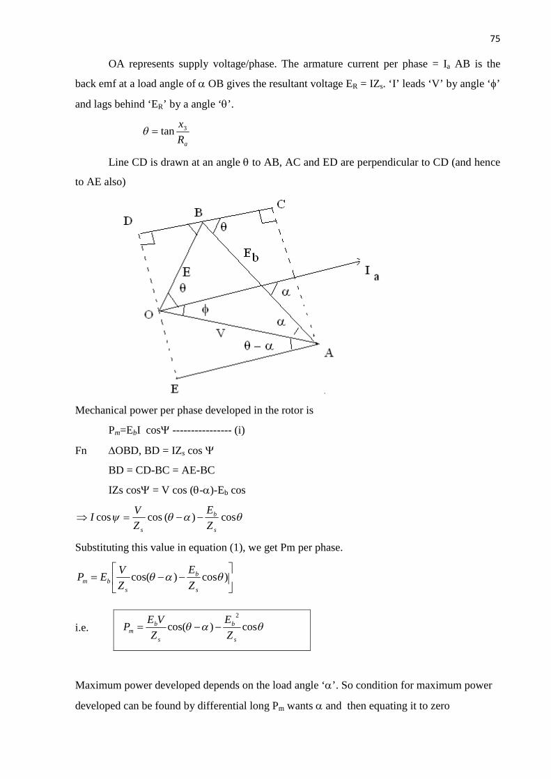
75
Contd…
OA represents supply voltage/phase. The armature current per phase = Ia AB is the
back emf at a load angle of a OB gives the resultant voltage ER = IZs. ‘I’ leads ‘V’ by angle ‘f’
and lags behind ‘ER’ by a angle ‘q’.
aR
x3tan=q
Line CD is drawn at an angle q to AB, AC and ED are perpendicular to CD (and hence
to AE also)
Mechanical power per phase developed in the rotor is
Pm=EbI cosY ---------------- (i)
Fn DOBD, BD = IZs cos Y
BD = CD-BC = AE-BC
IZs cosY = V cos (q-a)-Eb cos
qaqy cos )( cos coss
b
s ZE
ZV
I --=Þ
Substituting this value in equation (1), we get Pm per phase.
úû
ùêë
é--= )cos)cos( qaq
s
b
sbm Z
EZV
EP
i.e.
Maximum power developed depends on the load angle ‘a’. So condition for maximum power
developed can be found by differential long Pm wants a and then equating it to zero
qaq cos)cos( 2
s
b
s
bm Z
EZ
VEP --=

76
Contd…
0=ad
dPm
0cos)cos(2
=úû
ùêë
é--Þ qaq
a s
b
s
b
ZE
ZVE
dd
[ ) 00sin( =---Þ aqs
b
ZVE
0)sin( =--Þ aqs
b
ZVE
Þ sin (q-a) = 0
Þ sin (q-a) = sin 0
Þ q - a = 0
Þ q = a
Value of maximum power
aaq cos)cos()(2
maxs
b
s
bEm Z
EZ
VP --=
acos2
s
b
s
bE
ZE
Z
V-=
qcos2
s
b
s
bE
ZE
Z
V-=
Now, maximum power developed in the rotor depends on the value of internal angle ‘q’.
® When q = a = 90°
The power will be maximum.
s
bm Z
VEP =max)(
If ‘Tg’ is the grass rotor torque developed by the motor, then
rpsinN
NP
T
PNT
s
s
mg
msg
2
2
ïþ
ïý
ü
=Þ
=´
p
p
] [60/2
rpminNNP
T ss
mg p=Þ

77
Contd…
=´=Þs
mg N
PT
p260
Shaft torque is given as
N-M
Synchronous Motor with different excitations
(i) When Eb = V, is known as normal excitation
(ii) When Eb < V, is known as under excitation, lagging pf .
(iii) When Eb > V, is known as over excitation. leading pf.
The diagram shows the induced back emf in various pf.
i) Lagging pf:
AC2=AB2+BC2=[V-ERcos(q-.)]2+[ERsin(q-.)]2
Eb=
ii) Leading pf:
iii) Unity pf:
OB=IaRa, BC=IaXs
Eb=(V-IaRa)+jIaXs
ssh N
PT
oul55.9 =
mNNP
s
m -55.9

78
Contd…
Motor on Load
Þ Effect of varying excitation with constant load.
Suppose a synchronous motor is operating with normal excitation (Eb=V) at unity power factor
with a given load. The armature is drowning a power of Via per phase which is enough to meet
the mechanical load on the motor. The effect of changing excitation with load remains constant
is discussed below.
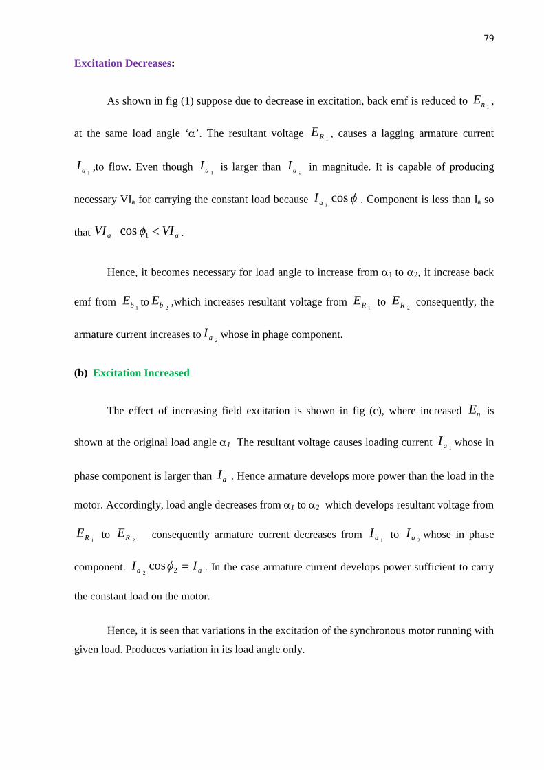
79
Contd…
Excitation Decreases:
As shown in fig (1) suppose due to decrease in excitation, back emf is reduced to 1 nE ,
at the same load angle ‘a’. The resultant voltage 1 RE , causes a lagging armature current
1 aI ,to flow. Even though 1 aI is larger than
2 aI in magnitude. It is capable of producing
necessary VIa for carrying the constant load because f cos 1 aI . Component is less than Ia so
that aa VIVI <1 cos f .
Hence, it becomes necessary for load angle to increase from a1 to a2, it increase back
emf from 1 bE to
2 bE ,which increases resultant voltage from 1 RE to
2 RE consequently, the
armature current increases to2 aI whose in phage component.
(b) Excitation Increased
The effect of increasing field excitation is shown in fig (c), where increased nE is
shown at the original load angle a1 The resultant voltage causes loading current 1 aI whose in
phase component is larger than aI . Hence armature develops more power than the load in the
motor. Accordingly, load angle decreases from a1 to a2 which develops resultant voltage from
1 RE to 2 RE consequently armature current decreases from
1 aI to 2 aI whose in phase
component. aa II =2 cos2
f . In the case armature current develops power sufficient to carry
the constant load on the motor.
Hence, it is seen that variations in the excitation of the synchronous motor running with
given load. Produces variation in its load angle only.
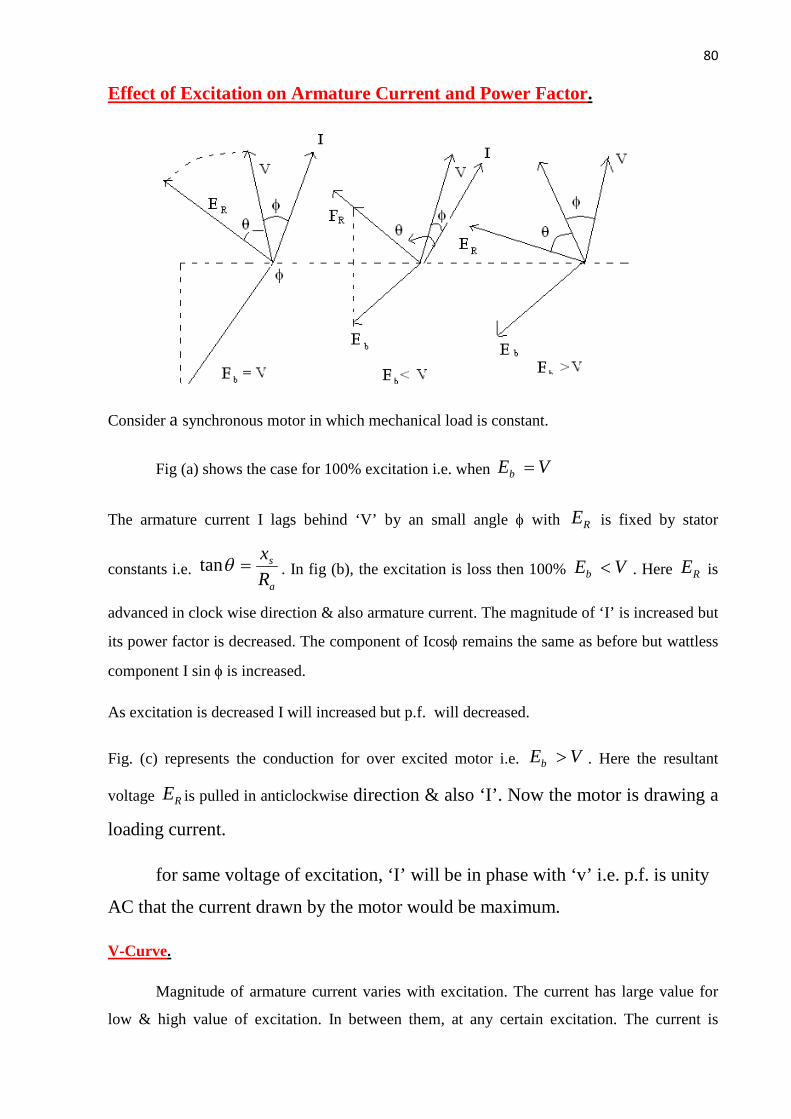
80
Contd…
Effect of Excitation on Armature Current and Power Factor.
Consider a synchronous motor in which mechanical load is constant.
Fig (a) shows the case for 100% excitation i.e. when VEb =
The armature current I lags behind ‘V’ by an small angle f with RE is fixed by stator
constants i.e. a
s
Rx
=qtan . In fig (b), the excitation is loss then 100% VEb < . Here RE is
advanced in clock wise direction & also armature current. The magnitude of ‘I’ is increased but
its power factor is decreased. The component of Icosf remains the same as before but wattless
component I sin f is increased.
As excitation is decreased I will increased but p.f. will decreased.
Fig. (c) represents the conduction for over excited motor i.e. VEb > . Here the resultant
voltage RE is pulled in anticlockwise direction & also ‘I’. Now the motor is drawing a
loading current.
for same voltage of excitation, ‘I’ will be in phase with ‘v’ i.e. p.f. is unity
AC that the current drawn by the motor would be maximum.
V-Curve.
Magnitude of armature current varies with excitation. The current has large value for
low & high value of excitation. In between them, at any certain excitation. The current is

81
Contd…
minimum. The variation of current ‘I’ with excitation is shown in fig below which is known as
V-curve. Since it looks like ‘V’.
Motor runs with loading p.f. when over-excited and with lagging p.f. when under
excited. In between, the power factor will be unity. The variation of p.f. with excitation (shown
in dotted line) which is known as inverted v-curve, since is looks like inverted ‘V’. It is seen
that the armature current will be minimum when the p.f. will be unity.
Synchronous Condenser / Capacitor
Both transformer & induction motor draws lagging currents from the lien on light
loads, the power drawn by them has a large reactive component and power factor is very low.
It is seen that an over-excited synchronous motor will run with leading p.f. by using
synchronous motor and transformers. The power factor can be increased and the reactive
components of power can be decreased when synchronous motors are used for this purpose (
p.f. improvement), is known as synchronous condenser or synchronous capacitor because it
draws a leading current from the line like a capacitors because it draws a leading current from
the line like a capacitor.
Hunting or Phase Swinging.
When synchronous motor is used for driving a varying load. Then a condition known as
hunting is produced. Hunting may also be caused if supply frequency is pulsating.
When a synchronous motor is loaded its rotor falls back in phase by the coupling angle
‘a’. As the load is progressively increased, thus angle also increases so as to produced motor
torque to meet with the increased load. If now there is a sudden decrease in the motor load, the
rotor is pull back to new value of ‘a’. In this way rotor starts oscillating about its new position
of equilibrium. Corresponding to the new load. If the time period of those oscillations equals to

82
Contd…
the natural time period of the machine, then mechanical resonance is set up. The amplitude of
these oscillations may become so large to throw the machine out of synchronous.
To stop the oscillations damper or damping grids are employed. These damper-consists
of (short circuited copper were in the faces of the field poles of the motor. The oscillatory
motion of the rotor sets up eddy currents in the dampers which flows in such a way as to
suppress the oscillations.
Comparison between induction motor and synchronous motor.
Induction Motor Synchronous Motor
1. Its speed decreases slightly as the load
increased.
1. It runs at either synchronous speed or not
at all
2. It always run with lagging power factor. 2. It can be run under a wide rang of p.f.
both lagging & leading.
3. It is self –starting. 3. It is inherently not self-starting.
4. D.C. excitation is not required 4. D.C. excitation is required.
5. It is cheap & simple 5. It is costlier & complicated.
Application of Synchronous Motor :
1. Power factor correction :
Over excited synchronous motor having leading p.f. are widely use for improving p.f.
of power systems.
2. Constant speed application.
High speed synchronous motor (above 600rpm) are used for centrifugal pumps, belt
driven reciprocating, compressor, blowers, line shafts, rubber & paper mills etc.
Low speed synchronous motors (below 600rpm) are used for drives such as centrifugal
and screw type pumps, balls and tube mills, vaccum pumps, choppers and metal rolling mills
etc.
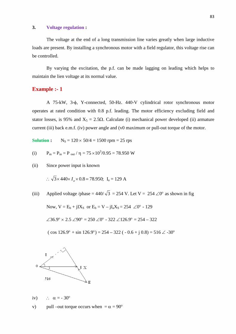
83
Contd…
3. Voltage regulation :
The voltage at the end of a long transmission line varies greatly when large inductive
loads are present. By installing a synchronous motor with a field regulator, this voltage rise can
be controlled.
By varying the excitation, the p.f. can be made lagging on leading which helps to
maintain the lien voltage at its normal value.
Example :- 1
A 75-kW, 3-f, Y-connected, 50-Hz. 440-V cylindrical rotor synchronous motor
operates at rated condition with 0.8 p.f. leading. The motor efficiency excluding field and
stator losses, is 95% and X5 = 2.5W. Calculate (i) mechanical power developed (ii) armature
current (iii) back e.m.f. (iv) power angle and (v0 maximum or pull-out torque of the motor.
Solution : NS = 120 ´ 50/4 = 1500 rpm = 25 rps
(i) Pm = Pin = P out / h = 75 ´103/0.95 = 78.950 W
(ii) Since power input is known
;950.788.04403 =´´´\ aI Ia = 129 A
(iii) Applied voltage /phase = 440/ 3 = 254 V. Let V = 254 Ð0° as shown in fig
Now, V = Eb + jIXS or Eb = V – jIaXS = 254 Ð0° - 129
Ð36.9° ´ 2.5 Ð90° = 250 Ð0° - 322 Ð126.9° = 254 – 322
( cos 126.9° + sin 126.9°) = 254 – 322 ( - 0.6 + j 0.8) = 516 Ð -30°
iv) \ a = - 30°
v) pull –out torque occurs when = a = 90°
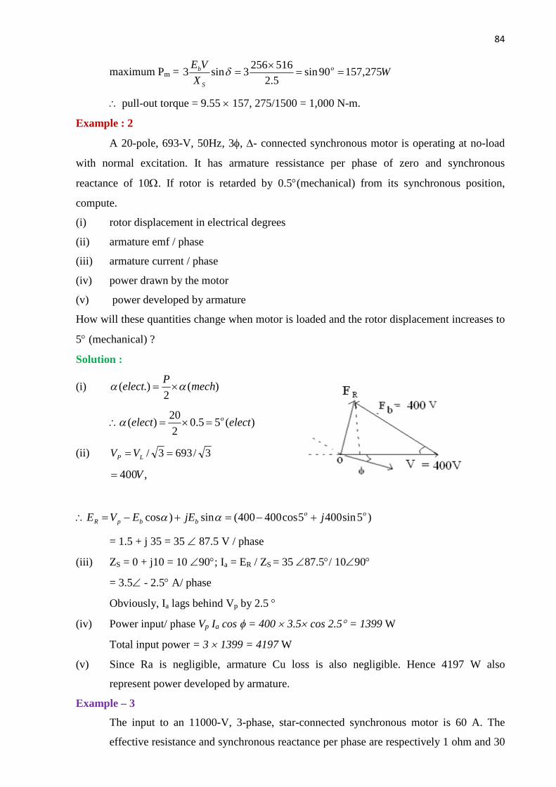
84
Contd…
maximum Pm = WX
VE o
S
b 275,15790sin5.2516256
3sin3 ==´
=d
\ pull-out torque = 9.55 ´ 157, 275/1500 = 1,000 N-m.
Example : 2
A 20-pole, 693-V, 50Hz, 3f, D- connected synchronous motor is operating at no-load
with normal excitation. It has armature ressistance per phase of zero and synchronous
reactance of 10W. If rotor is retarded by 0.5°(mechanical) from its synchronous position,
compute.
(i) rotor displacement in electrical degrees
(ii) armature emf / phase
(iii) armature current / phase
(iv) power drawn by the motor
(v) power developed by armature
How will these quantities change when motor is loaded and the rotor displacement increases to
5° (mechanical) ?
Solution :
(i) )(2
.)( mechP
elect aa ´=
)(55.0220
)( electelect o=´=\a
(ii) 3/6933/ == LP VV
,400V=
)5sin4005cos400400(sin)cos oobbpR jjEEVE +-=+-=\ aa
= 1.5 + j 35 = 35 Ð 87.5 V / phase
(iii) ZS = 0 + j10 = 10 Ð90°; Ia = ER / ZS = 35 Ð87.5°/ 10Ð90°
= 3.5Ð - 2.5° A/ phase
Obviously, Ia lags behind Vp by 2.5 °
(iv) Power input/ phase Vp Ia cos f = 400 ´ 3.5´ cos 2.5° = 1399 W
Total input power = 3 ´ 1399 = 4197 W
(v) Since Ra is negligible, armature Cu loss is also negligible. Hence 4197 W also
represent power developed by armature.
Example – 3
The input to an 11000-V, 3-phase, star-connected synchronous motor is 60 A. The
effective resistance and synchronous reactance per phase are respectively 1 ohm and 30
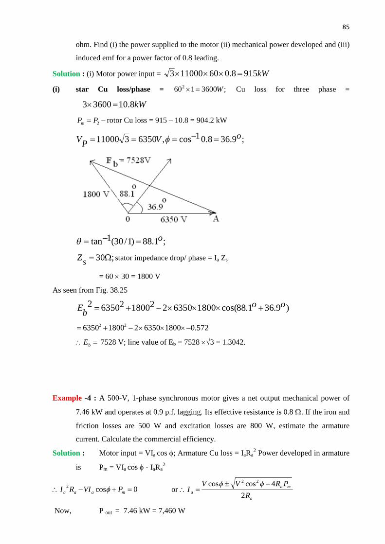
85
Contd…
ohm. Find (i) the power supplied to the motor (ii) mechanical power developed and (iii)
induced emf for a power factor of 0.8 leading.
Solution : (i) Motor power input = kW9158.060110003 =´´´
(i) star Cu loss/phase = ;36001602 W=´ Cu loss for three phase =
kW8.1036003 =´
-= 2PPm rotor Cu loss = 915 – 10.8 = 904.2 kW
;9.368.01cos,6350311000 oVPV =-=== f
;1.88)1/30(1tan o=-=q
;30W=sZ stator impedance drop/ phase = Ia Zs
= 60 ´ 30 = 1800 V
As seen from Fig. 38.25
)9.361.88cos(18006350221800263502 oobE +´´´-+=
572.018006350218006350 22 -´´´-+=
=\ bE 7528 V; line value of Eb = 7528 ´Ö3 = 1.3042.
Example -4 : A 500-V, 1-phase synchronous motor gives a net output mechanical power of
7.46 kW and operates at 0.9 p.f. lagging. Its effective resistance is 0.8 W. If the iron and
friction losses are 500 W and excitation losses are 800 W, estimate the armature
current. Calculate the commercial efficiency.
Solution : Motor input = VIa cos f; Armature Cu loss = IaRa2 Power developed in armature
is Pm = VIa cos f - IaRa2
0cos2 =+-\ maaa PVIRI f or a
maa R
PRVVI
2
4coscos 22 -±=\
ff
Now, P out = 7.46 kW = 7,460 W

86
Contd…
Pm = Pout + iron and friction losses + excitation losses
= 7460 + 500 + 800 = 8760 W
AIa 2.206.13.32
6.17.417450
8.02
37608.04)9.0500(9.0500 2
==±
=´
´´-´±´=
Example :- 5
The synchronous reactance per phase of a 3-phase star-connected 6.600 V synchronous
motor is 10W. For a certain load , the input is 900 kW and the induced line emf is 8,900 V.
(line value) Evaluate the line current. Neglect resistance.
Solution : Applied voltage / phase = 6.600/ Ö3 = 3, 810 V
Back e.m.f. / phase = 8,900 / Ö 3 = 5, 140 V
Input = 000.900cos.3 =fIVL
\ fcosI = 9´ 105 / Ö3´6.600 = 78.74 A
In D ABC of vector digram in Fig we have AB2 = AC2 +BC2
Now OB = I.XS = 10 I
BC = OB cos f = 10 ´ 78.74 = 787.4 V
\ 5,1402 = 787.42+ AC2
\ AC = 5,079 V
OC = 5,079 – 3, 810 = 1, 269 V
Tan f = 1269/787.4 = 1.612 f = 58.2°, cosf = 0527
Now I cos f = 78.74; I = 78.74/0.527 = 149.4 A

87
Contd…
CHAPTER-IV
Single Phase induction Motor
A single phase Induction Motor (I.M.) is very similar to 3 Phase squirrel cage I.M. It
has a squirrel cage rotor and a single phase winding on stator like 3 phase I.M., single phase
I.M. is not self starting. The stator winding produces a magnetic field which polarity
reversed after each half cycle. So the field don’t produce rotating field. If a single phase I.M.
having squirrel cage rotor and 1-phase distributed stator winding, it doesn’t develop any
resulting starting torque as the torque developed in both the cycle neutralize each other. To
make the I.M. starting, we have to add an another winding in the stator circuit is known as
auxiliary winding (starting)
Making Single Phase I.M. Self starting :
To make a 1-phase I.M. self starting we should some how produce a revolving stator
magnetic field, this may be achieved by converting a 1-phase supply in to two phase supply
by using an additional winding. Hence the rotor of the single phase motor starts rotating like
3 phase motor. When it achieves sufficient speed, the additional winding may be removed.
But the rotor continue running.
Different types of single phase I.M.-
1. Induction Motors like split-phase, capacitor and shaded pole type.
2. Repulsion type motors
3. A.C. series motors (Commutator motors) etc.
Split Phase Motor:
The Stator circuit of a split phase I.M. is added with an auxiliary winding with the
main winding and it is located 900 electrically apart from the main winding. The two
windings are so designed that the auxiliary winding has high resistance and small reactance
while the main winding has low resistance and large reactance.

88
Contd…
Operation-
When supply is given to the starter windings both the windings are energized. Since
main winding is made by highly inductive while the auxiliary winding is resistive that
produce a weak revolving field for which it produces revolving flux and rotor starts revolving
hence the motor started.
The Torque produced is,
Ts = K Im Is Sin α
When α is the phase angle between Im & Is. When the motor achieves about 75 % of
synchronous speed, the centrifugal switch S will open and the auxiliary winding is cut off
from the circuit. Then the motor operates as a 1 – Ф I.M. and it continues to accelerate till it
reaches it’s normal speed which is below the synchronous speed. The starting torque is
proportional to the Current
If the starting period delay exceeds 5 Seconds, the winding may burn out because the winding
made of fine wire.
Uses
Fan, Washing machine, small machine tools etc.
Capacitor Start I.M. :
A Capacitor start motor is identical to a split phase motor except that the starting winding has
same number of turns as main winding and a capacitor is connected in series with the starting
winding.
Figure 1 split phase I M motor

89
Contd…
Operation
The value of the capacitor is such that “Is” leads “Im” by The starting torque which is
more than the split phase I.M. When torque is produced, the rotor starts rotating. When the
rotor achieves 75 % of the Ns, the centrifugal switch will be open. Then auxiliary winding is
cut off from the circuit. The motor then operate as a 1-phase I.M. and continue to accelerate
till it reaches it’s normal speed.
Advantages
It’s starting characteristics are better than the split phase I.M. For the same starting
torque, the current of starting winding is only about half that in split phase I.M. so, it is
heated less quickly.
Uses :
It is used where low starting torque is required.
Capacitor start and run
It is similar to capacitor start motor except that the starting winding is not opened
after starting. So, when the motor runs both windings are connected in the circuit . It has two
capacitors with the starting winding. The capacitor C1 has smaller capacity than C2 and is
connected in the circuit in series with the starting winding permanently during starting as well
as running. The large capacitor C2 is connected in parallel in C1 for starting purpose only.
When the motor approaches about 75 % of Ns then Centrifugal switch is opened and the
capacitor C2 is disconnected from circuit.
Figure 2 Capacitor Start I.M.

90
Contd…
Figure 3 capacitor start induction motor
The important kind of capacitor motor is permanent capacitor motor. In such type the
capacitor is permanently connected to the circuit and one in number only.
Figure 4 permanent capacitor motor
Characteristics
This type of motor is designed for perfect 2–phase operation at any load and it
produces continuous torque as compared to induction motor.
Uses
Due to it’s continuous torque and vibration free, it is used in hospitals, studio,
refrigerators, compressors, stokers, ceiling fan, blowers etc.
Shaded Pole Motor
The shaded pole motor is very popular for rating up to 0.05 HP. A small portion of pole core
of about 30% is slot cut and surrounded by a short circuited ring of Cu strip called shading
coil.
Figure 5 shaded pole motor

91
Contd…
Operation
From the total of core, the flux produced and emf is induced in the shading
coil. The resulting current in shading coil is in such a direction, so as to oppose I and
so the charge in flux according to Lens’s law. So this flux in the shaded portion of the
pole is weakened while in the unshaded portion is strengthened. The magnetic axis
lies along the middle of this part.
Figure 6 torque in shaded pole motor
During the portion in AB as shown in figure (6), the flux is reached almost maximum
value, the flux distribution across the pole is uniform. Since no current is flowing in shading
coil, the magnetic axis shift to the centre of the pole.
As the flux decreases as shown in figure (6), from B to C, This again set a induced
current in the shading coil. This current flows in such a direction that to oppose the decrease
in current. Thus the flux in the shaded portion of the pole is strengthened while the unshaded
portion is weakened. So the magnetic axis shift to the middle part of the shaded pole.
This shifting of flux is like a rotating weak field moving in the direction from
unshaded portion to shaded portion of the pole. Under the influence of the moving field a
small staring torque is developed which torque starts to rotate the rotor, additional torque is
produced by single phase motor action. Such motors are built in very small sizes of 5-50w
but are simple in construction and are extremely rugged, reliable and cheap.they do not need
any commutator, switch, brush, collector rings etc. However they suffer from disadvantages
of (i) low starting torque, (ii) very little over load capacity and (iii) very low efficiency
ranging from 5% to 35% from lower to higher ratings respectively.
Uses
It is used in small fans, toys, hair drier of power up to 50 W.
AC Series Motor / Universal Motor
The construction of AC series motor is as like as DC series motors. If a DC Series motor
is connected to an AC supply, it will rotate and produce unidirectional torque because the

92
Contd…
current flowing in both the armature and field reverses at the same time. When a DC series
motor operates on a single phase supply, then it is called a AC series motor. The
performances of this type of motor will not be satisfactory due to the following reasons.
1. The alternating flux would cause excessive eddy current loss in the yoke and the field
core will become extremely heated.
2. Sparking will occur at brushes because of huge voltage and current induced in the
short circuited armature coil during commutation period.
3. Power factor is very low.
Due to the above drawbacks DC series motor required some changes by which AC
supply input disadvantages solved.. The changes made are
a) The entire magnetic circuit is laminated in order to reduce the eddy current losses.
b) A high field flux is obtained by using a low reluctance magnetic circuit.
c) Excessive sparking eliminated by using high resistance leads to connect the coil to the
commutator segment.
Though this type of motor can be operated either on AC or DC supply, the resulting
torque speed curve is same. It is also known as Universal motor.
Operation
When it is connected to an AC supply the same alternating current flows through the
field and armature winding. The field winding produces an alternating flux that react with an
armature current to produce a torque and the direction of the torque is always same because
they (current and flux) reverses simultaneously.
Characteristics
a) Speed increases to a high value with a decreasing load.
b) It has very high starting torque.
c) At Full load, the power factor is 90 %.
Uses.
a. Sewing machine b. vacuum cleaners, c. mixer grinders and blenders
d) High speed vacuum cleaners. e. hair driers f. power saw
f. Drills g. Electric Shaver.
Single Phase Repulsion Motor
A repulsion motor is similar to an Ac Series motor except some modification. The
brushes are not connected to supply but are short circuited by themselves. The current
induced in the armature conductor by mutual induction method.

93
Contd…
Construction Single Phase Repulsion Motor
Figure 7 Single Phase Repulsion Motor
The field of the stator winding is connected directly to the AC single phase source.
The rotor is similar to a DC motor armature winding connected to the commutator. The
brushes are short circuited which make the rotor squirrel cage type. It has very high starting
torque and also better power factor as compared to other single phase motor.
Operation
The figure shows, two pole repulsion motor with short circuited brushes. The brush
axis is parallel to stator field. The emf is induced in the armature Conductor by induction
method and current flows through the rotor conductors. The current flows from N to S brush
in two paths. during this brush position half of the rotor conductors under N pole carry
current inward and half carry current outward. The same thing occurs under S pole.
Therefore, same torque is produced in opposite direction in both the half coils. So the net
torque is zero.
If the brush axis is in some angle other than 00 or 900, then a torque is developed in the
rotor and accelerate the rotor to final speed. The brush axis is shifted in clockwise direction
through some angle from stator field axis. The emf is induced in same direction, the current
flows in two paths of the rotor winding between N & S. Now the more conductors under
North pole carrying current in one direction while more conductors under south pole carrying
current in opposite direction, so that the torque is developed in clockwise direction and the
rotor rotates to it’s final speed.
The direction of rotation of the rotor depends upon the direction in which the brushes
are shifted. If the brushes are shifted in clockwise direction from the stator field axis then the
net torque in clockwise direction. It has high starting torque.
Use
Commercial refrigerators, compressors and pumps.

94
Contd…
CHAPTER -V
COMMUTATOR MOTORS
A.C. Series Motor or Universal Motor
A dc series motor will rotate in the same direction regardless of the polarity of the
supply.
When a dc series motor operates on a single phase ac supply it is called an AC series
motor. However some changes are required in a DC motor so that it can satisfactorily
operates on A.C. supply.
The changes are as follows:
i) The field core is constructed of a material having low hysteresis loss. It is laminated
in order to reduce eddy current loss. Hence A.C. series motor requires a more
expensive construction than a D.C. series motor.
ii) The series field winding uses as few turns as possible to reduce the reactance of the
field winding to minimum. This reduces the voltage drop across the field winding.
iii) A high field flux is obtained by using low reluctance magnetic circuit.
iv) There is considerable sparking between the brushes and the commutator when the
motor is used on A.C. supply. It is because the alternating flux establishes high currents in the
coils short circuited by the brushes. When the short circuited coils break contact from the
commutator, excessive sparking is produced. This can be eliminated by using high resistance
leads to connect the coils to the commutator segments.
v) In order to reduce the effect of armature reaction thereby improving commutation and
reducing armature reactance a compensating winding is used. This winding is put in
the stator slot.
The drawback when A.C. supply is given to D.C. series motor (without modification)
–
i) The efficiency is low due to hysteresis and eddy current loss.
ii) The power factor is low due to large reactance of the field and armature winding.
iii) The sparking at the brush is excessive.
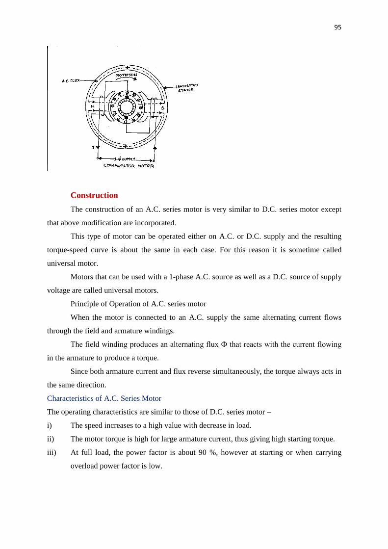
95
Contd…
Construction
The construction of an A.C. series motor is very similar to D.C. series motor except
that above modification are incorporated.
This type of motor can be operated either on A.C. or D.C. supply and the resulting
torque-speed curve is about the same in each case. For this reason it is sometime called
universal motor.
Motors that can be used with a 1-phase A.C. source as well as a D.C. source of supply
voltage are called universal motors.
Principle of Operation of A.C. series motor
When the motor is connected to an A.C. supply the same alternating current flows
through the field and armature windings.
The field winding produces an alternating flux Ф that reacts with the current flowing
in the armature to produce a torque.
Since both armature current and flux reverse simultaneously, the torque always acts in
the same direction.
Characteristics of A.C. Series Motor
The operating characteristics are similar to those of D.C. series motor –
i) The speed increases to a high value with decrease in load.
ii) The motor torque is high for large armature current, thus giving high starting torque.
iii) At full load, the power factor is about 90 %, however at starting or when carrying
overload power factor is low.

96
Contd…
Application
The fractional horsepower A.C. series motor have high speed and large starting torque.
Therefore be used to drive –
a) High speed vacuum cleaners.
b) Sewing Machine
c) Electric Shavers
d) Drills
e) Mechanical tools etc.
Repulsion Motor
A repulsion motor is similar to an A.C. series Motor except –
i) The brushes are not connected to supply but are short circuited. Hence current are induced
in the armature conductor by transformer action.
ii) The field structure has non-silent pole construction
By adjusting the position of short circuited brushes on the commutator, the starting torque
can be developed in the motor.
Construction
The field of the stator winding is connected to the 1 – Ф A.C. supply.
The armature or rotor with drum type winding like D.C. motor is connected to a commutator.
Here the brushes are not connected to the supply but are connected to each other or short
circuited. Hence it is possible to vary the starting torque by changing the brush axis. So
Commutator motor has better power factor than conventional 1-phase motor.
Principle of Operation
Fig. 1 shows two pole repulsion motor with its two short-circuited brushes
When field current is increasing in the direction shown the left hand pole is north pole and
right hand pole is south pole.
i) Here the brush axis is parallel to the stator field.
When the stator winding is energized from 1 – Ф supply emf is induced in the armature
conductor by induction. This emf will cause a current to flow in the armature conductor. By
lens’s law the direction of the emf is such that magnetic field of the resulting armature current
will oppose the increase in flux.
The current direction in armature conductor is shown in the Fig.

97
Contd…
With brushes set in this position, half of the armature conductors under the N-pole carry
current inward and half carry current outward. The same is true under south pole.
So as much torque is developed in one direction as in the other and the armature remains
stationary.
The armature will also remain stationary if the brush axis is perpendicular to the stator field
axis as even then net torque is zero.
If the brush axis is at some angle other than 00 or 900 to the axis of stator field a net torque is
developed on the rotor and rotor accelerate to it’s final speed.
Here in figure 2 because of the new brush position, the greater part of the conductor under the
N-pole carry current in one direction. While the greater part of conductor under S-pole carry
current in opposite direction.
With brushes in position 2 torque in developed in the clockwise direction and the rotor
quickly attains the final speed.
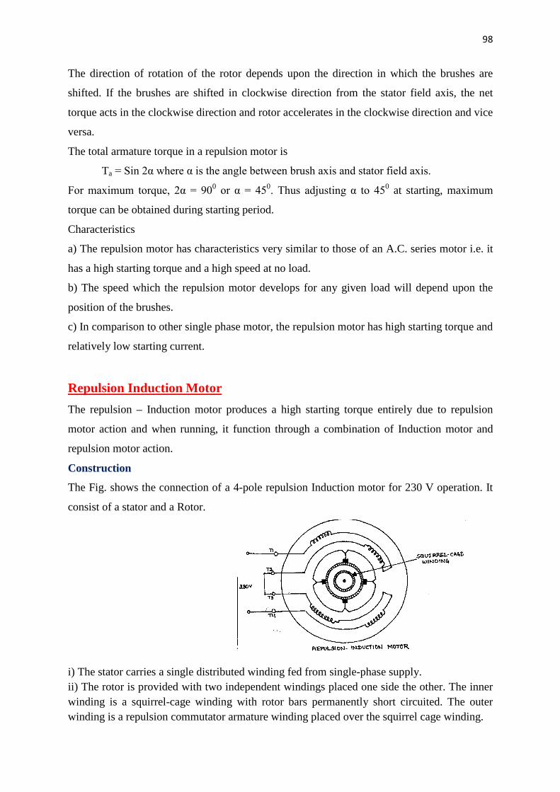
98
Contd…
The direction of rotation of the rotor depends upon the direction in which the brushes are
shifted. If the brushes are shifted in clockwise direction from the stator field axis, the net
torque acts in the clockwise direction and rotor accelerates in the clockwise direction and vice
versa.
The total armature torque in a repulsion motor is
Ta = Sin 2α where α is the angle between brush axis and stator field axis.
For maximum torque, 2α = 900 or α = 450. Thus adjusting α to 450 at starting, maximum
torque can be obtained during starting period.
Characteristics
a) The repulsion motor has characteristics very similar to those of an A.C. series motor i.e. it
has a high starting torque and a high speed at no load.
b) The speed which the repulsion motor develops for any given load will depend upon the
position of the brushes.
c) In comparison to other single phase motor, the repulsion motor has high starting torque and
relatively low starting current.
Repulsion Induction Motor
The repulsion – Induction motor produces a high starting torque entirely due to repulsion
motor action and when running, it function through a combination of Induction motor and
repulsion motor action.
Construction
The Fig. shows the connection of a 4-pole repulsion Induction motor for 230 V operation. It
consist of a stator and a Rotor.
i) The stator carries a single distributed winding fed from single-phase supply. ii) The rotor is provided with two independent windings placed one side the other. The inner winding is a squirrel-cage winding with rotor bars permanently short circuited. The outer winding is a repulsion commutator armature winding placed over the squirrel cage winding.
99
Contd…
The repulsion winding is connected to a commutator on which ride short circuited brushes. Operation When single phase stator winding is driven by an A.C. supply the repulsion winding is active. Consequently the motor starts as a repulsion motor with a corresponding high starting torque. As the motor speed increases, the current shifts from the outer to inner winding due to the decreasing impedance of the inner winding with increasing speed. Consequently at running speed, the squirrel cage winding carries the greater part of rotor current. This shifting of repulsion motor action to induction motor action is thus achieved without any switching arrangement. It may be seen that the motor starts as a repulsion motor. When running, it function through a combination of principle of induction and repulsion. Characteristics The no-load speed of a repulsion – Induction Motor is somewhat above the synchronous speed because of the effect of repulsion winding, however the speed at full load is slightly less than the synchronous speed in an induction motor. The speed regulation of the motor is about 6 %. The starting torque is 2.25 to 3 times the full load torque. The starting current is 3 to 4 times the full load current. Application This type of motor is used for applications requiring a high starting torque with essentially constant running speed. Repulsion – Start Induction – Run motor The action of repulsion motor is combined with that of a 1 – Ф induction motor to produce repulsion – start induction – run motor (also called Repulsion Start Motor) This motor starts as an ordinary repulsion motor, but after it reaches about 75 % of its full speed, Centrifugal short – circuiting device / switch short circuits its commutator. From then on it runs as an Induction Motor with a short – circuited squirrel – Cage Rotor. After the commutator is short circuited, brushes do not carry any current, hence they may also be lifted from the commutator in order to avoid unnecessary wear and tear and friction losses. Characteristics The starting torque is 2.5 to 4.5 times the full load torque and the starting current is 3.75 times the full load value. Due to their high starting torque, repulsion motors were used to operate devices such as refrigerators, pumps, compressor etc.
100
Contd…
CHAPTER- VI
SPECIAL PURPOSE ELECTRIC MACHINES
INTRODUCTION
Special purpose electric machines have some features that distinguishes them from
conventional machines.Stepper motor belongs to that type machine which rotates by a
specific number of degrees in response to an input electrical signal and is widely used in
digital control systems.
STEPPER MOTOR
Stepper motors are also known as stepping motors or step motors. A stepper motor is an
electro-magnetic motor that rotates by a specific number of degrees in response to an input
electrical signal. Typical step sizes are ,2 , 7 , for each electrical pulse. Note that
there is no continuous energy conversion so that the rotor does not rotate continuously as in a
conventional electric motor.The stepper motor converts electrical pulses into proportionate
mechanical movement. Each revolution of stepper motor is made up of a series of definite
individual steps. a step is defined as the angular rotation in degrees of the motor each time it
receives the electrical pulse. such a step control is required in many applications. Figure 1.1
illustrates a simple application for a stepper motor. Each time the controller receives an input
electrical signal, the paper is driven to a certain incremental distance. Stepper motors are
relatively cheap and simple in construction and can be made to rotate in steps in either
direction. These motors are excellent candidates for such applications as type-writers, control
of floppy disc drives, numerical control of machine tools etc. The two most popular types of
stepper motors are :
(i) Permanent-magnet (PM) Stepper Motor
(ii) Variable –reluctance(VR) Stepper Motor

101
Contd…
Fig. 1.1
The stator of a stepper motor of either type above carries stator windings which
are energized from a dc source to create two or more stator poles. The stator poles
are also called stator teeth. The rotor of a stepper motor may be a permanent
magnet as in a Permanent Magnet stepper motor or a soft-iron material as in
case of a variable reluctance motor. The rotor may also have two or more poles.
The rotor poles are also called rotor teeth.
The stator coils are energized in groups referred to as phases. The stator
windings may be 2-phase,3-phase or 4-phase windings. The phase windings are
brought out to terminals for DC excitation .
PM Stepper Motor
The figure1.2 shows a two-pole 1-phase permanent magnet stepper motor. When
the stator is energized, the excitation torque acts on the rotor. The rotor will
move to a position where the excitation torque is zero i.e. the rotor will be aligned in
parallel to the stator field.
Fig.1.2 Fig.1.3

102
Contd…
Fig 1.3 shows how excitation torque varies with thee rotor position for a PM
rotor. Note that maximum torque is developed when the rotor is displaced from
the stator field by either or . However , the torque is zero and the rotor
is aligned (parallel) with the stator field.
(iii) VR Stepper Motor
Fig. 1.4 shows a 2-pole , single phase variable-reluctance(VR) stepper
motor.When the stator is energized ,reluctance torque acts on the rotor
(soft-iron material). The rotor will move a position where reluctance is minimum
and air-gap flux is maximum. This means that rotor teeth will align with the
energized stator poles.
Fig.1.4 Fig.1.5
Fig.1.5 shows how reluctance torque varies with the rotor position for a VR soft-
iron rotor.With the rotor at or , no torque is developed. Maximum torque is
developed at and Which is the position where reluctance torque forces
the rotor or move to position of minimum reluctance.
step angle :the angle through which the motor shaft rotates for each command
pulse is called step angle. It can be shown that for any PM or VR stepper
motor,the step angle can be found from the following two relation:
i) In terms of stator poles ( ) and rotor poles ( ), the step angle (α) is given
by:
Step angle, α= x
where α= Step angle in degrees
103
Contd…
( )=Number of stator poles(or teeth)
( )=Number of rotor poles (or teeth)
ii) In terms of stator phases (m) and rotor poles ( ), the step angle is given by:
step angle,α= α=
α= step angle in degrees
m=Number of stator phases
=Number of rotor poles (or teeth)
stepping rate. An important specification of a stepper motor is the stepping rate. The
number of steps per second is known as stepping frequency(f).The actual speed of a
stepper motor depends on the step angle (α) and stepping frequency(f) and is given by :
Speed of stepper motor, N =
N = motor speed in r.p.m.
f = stepping frequency i.e. steps/second
Example 1.1
Determine the step angle of a variable-reluctance stepper motor with 12 teeth in the stator
and 8 rotor teeth.
Solution :
Number of stator teeth, = 12
Number of rotor teeth, = 8
Step angle, α= x = x = /step
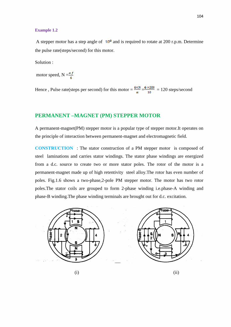
104
Contd…
Example 1.2
A stepper motor has a step angle of and is required to rotate at 200 r.p.m. Determine
the pulse rate(steps/second) for this motor.
Solution :
motor speed, N =
Hence , Pulse rate(steps per second) for this motor = = = 120 steps/second
PERMANENT –MAGNET (PM) STEPPER MOTOR
A permanent-magnet(PM) stepper motor is a popular type of stepper motor.It operates on
the principle of interaction between permanent-magnet and electromagnetic field.
CONSTRUCTION : The stator construction of a PM stepper motor is composed of
steel laminations and carries stator windings. The stator phase windings are energized
from a d.c. source to create two or more stator poles. The rotor of the motor is a
permanent-magnet made up of high retentivity steel alloy.The rotor has even number of
poles. Fig.1.6 shows a two-phase,2-pole PM stepper motor. The motor has two rotor
poles.The stator coils are grouped to form 2-phase winding i.e.phase-A winding and
phase-B winding.The phase winding terminals are brought out for d.c. excitation.
(i) (ii)

105
Contd…
(iii)
Fig.1.6
OPERATION : for this PM stepper motor,the number of rotor poles, = 2 and number
of phases, m=2.
Step angle, =m = /(2x2)= /step
(i) When only phase-A winding is energized by a constant current as shown in
Fig.1.6(i) stator tooth 1 becomes the south pole. This makes the north pole of the
PM rotor to align parallel with the south pole(stator tooth 1) of the stator. The
rotor will remain locked in this position as long as phase-A winding remains
energized. The first row of truth table in Fig. shows that only phase-A winding is
excited while phase-B winding is unexcited. Under this condition, step angle
= .The applied voltage waveforms in Fig also tally with the facts shown in the
truth table.
(ii) If phase A winding is de-energized and phase-B winding is energised as shown in
Fig.1.6(ii), stator tooth 2 becomes south pole. As a result, the north pole of the PM
rotor aligns parallel with the south pole(stator tooth2) of the stator. Thus the rotor
has displaced in the anticlockwise direction.
(iii) If phase B winding is de-energized and phase-A winding is excited by a reverse
current the rotor will further rotate in anticlockwise direction as shown in
Fig1.6(iii). Now the north pole of PM motor aligns with the stator tooth 3.

106
Contd…
Fig.1.7
Fig.1.8
(iv) So far the rotor has completed one-half revolution. However, if we continue the
appropriate switching the rotor will complete one revolution in steps.
We can change the step angle of a PM stepper motor by changing the
number of rotor poles and the number of phases(m).Thus for a 3-phase,24-
pole PM stepper motor, the step angle = /mNr= /3x24= /step.
Limitations : The PM stepper motor has the following draw\backs :
i) It is difficult to make a small permanent magnet rotor with a large number of poles.
Therefore ,PM stepper motors are restricted to large step angles in the range of
to .
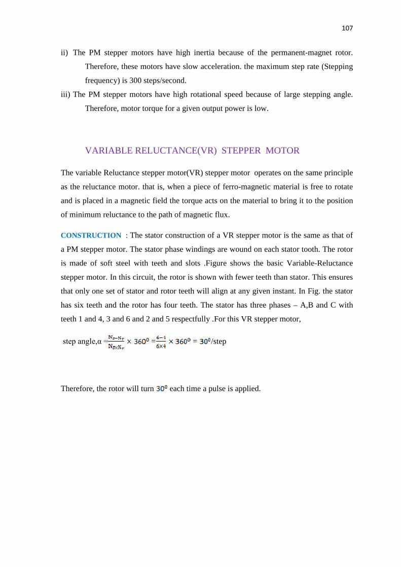
107
Contd…
ii) The PM stepper motors have high inertia because of the permanent-magnet rotor.
Therefore, these motors have slow acceleration. the maximum step rate (Stepping
frequency) is 300 steps/second.
iii) The PM stepper motors have high rotational speed because of large stepping angle.
Therefore, motor torque for a given output power is low.
VARIABLE RELUCTANCE(VR) STEPPER MOTOR
The variable Reluctance stepper motor(VR) stepper motor operates on the same principle
as the reluctance motor. that is, when a piece of ferro-magnetic material is free to rotate
and is placed in a magnetic field the torque acts on the material to bring it to the position
of minimum reluctance to the path of magnetic flux.
CONSTRUCTION : The stator construction of a VR stepper motor is the same as that of
a PM stepper motor. The stator phase windings are wound on each stator tooth. The rotor
is made of soft steel with teeth and slots .Figure shows the basic Variable-Reluctance
stepper motor. In this circuit, the rotor is shown with fewer teeth than stator. This ensures
that only one set of stator and rotor teeth will align at any given instant. In Fig. the stator
has six teeth and the rotor has four teeth. The stator has three phases – A,B and C with
teeth 1 and 4, 3 and 6 and 2 and 5 respectfully .For this VR stepper motor,
step angle,α = = = /step
Therefore, the rotor will turn each time a pulse is applied.
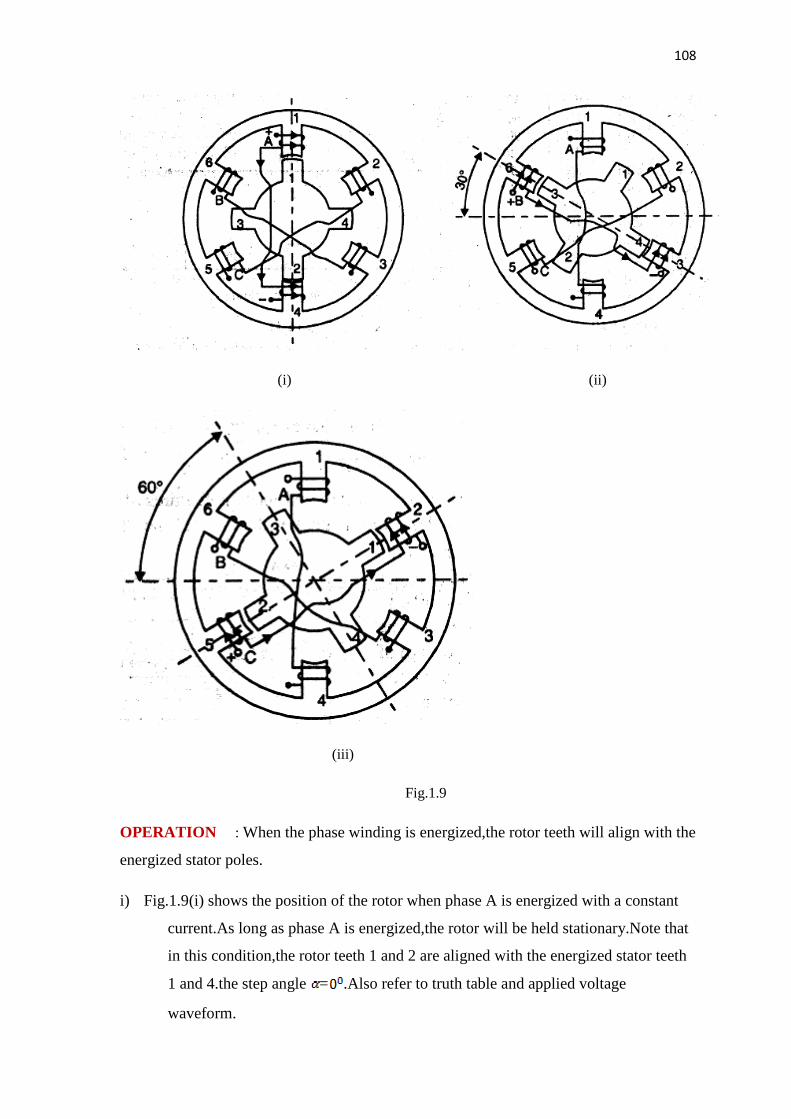
108
Contd…
(i) (ii)
(iii)
Fig.1.9
OPERATION : When the phase winding is energized,the rotor teeth will align with the
energized stator poles.
i) Fig.1.9(i) shows the position of the rotor when phase A is energized with a constant
current.As long as phase A is energized,the rotor will be held stationary.Note that
in this condition,the rotor teeth 1 and 2 are aligned with the energized stator teeth
1 and 4.the step angle = .Also refer to truth table and applied voltage
waveform.

109
Contd…
ii) when phase A is switched off and phase B is energized,the rotor will turn
clockwise so that the rotor teeth 3 and 4 align with the energized stator teeth 6 and
3.
iii) The effect of de-energising phase B and energizing phase C is shown in Fig.1.9(iii).In
this circuit,the rotor has further moved clockwise so that rotor teeth 1 and 2
align with energized stator teeth 2 and 5.
iv) after the rotor has displaced clockwise from iots starting point,the step sequence
has completed one cycle. The truth table in fig. shows the switching sequence to
complete a full rotation for the motor with six stator poles and four rotor
poles.
Fig.1.10 Fig.1.11
The direction of rotation will be reversed if the switching sequence is in the order
of A,C and B.For this particular motor,applied voltage must have at least five
cycle for one revolution.
HYBRID STEPPER MOTOR
The hybrid stepper motor combines the features of the PM and the VR stepper
motors.The torque developed by this motor is greater than that of the PM or VR stepper
motor.

110
Contd…
Construction : Fig1.12 shows the basic construction of a hybrid stepper motor.The stator
construction is similar to that of a VR or PM stepper motor. However, the rotor
construction combines the design of the rotors of a VR and a PM stepper motor. The rotor
of a hybrid stepper motor consists of two identical stacks of soft iron as well as an axially
magnetized round permanent magnet. Soft iron stacks are attached to the north and south
poles of the permanent magnet as shown in Fig.1.12
Fig 1.12
The rotor teeth are machined on the sot iron stacks. Thus the rotor teeth on one end
become the north pole and those at the other end become the south pole.
This rotor teeth of both north and south poles are displaced in angle for the proper
alignment of the rotor pole with that of the stator as shown in Fig.1.12
OPERATION : The operating mode of the hybrid stepper motor is very similar to that of
a PM or VR stepper motor.The phase windings are energized in proper sequence and the
111
Contd…
rotor rotaes in steps.Unlike the VR or PM stepper motors,the step angle of a hybrid
stepper motor is independent of the number of stator phases and depends only on the
number of rotor teeth( ).It is given by :
Step angle, α = / in deg
For a hybrid stepper motor having 5 rotor teeth,the step angle alpha = / = /5
= /step. It means that for each change of stator excitation,the rotor will turn by a step of
.
It may be noted that a hybrid stepper motor operates under the combined principles of the
PM and VR stepper motors.Therefore,the hybrid motor develops both excitation torqe
and relucatance torque.Consequently the resultant torque developed by the hybrid stepper
motor is greater than that of the PM or VR stepper motor.
…………………………………………..xxxxxxxxxxxxxxx………………………………………

112
Contd…
CHAPTER VII
THREE PHASE TRANSFORMER
All alternating current electrical energy is nearly generated by three phase alternating
current generators. Similarly three phase systems are used for transmission and distribution of
electrical energy. There are several reasons why a three phase system is preferred over a
single phase system. Some of the important reasons are
· Smaller size - KVA ratings of three phase generators and horse power ratings of three
phase motors for a given physical size are higher than those of similar single phase
units.
· Superior operating characteristics - operating characteristics of three phase motors and
other appliances are superior to those of similar single phase units.
· Better efficiency - the efficiency of transmission and distribution of power in three
phase system are better than in a single phase system.
Alternating current generated through a three phase generator has to be
transmitted at higher voltage level for economic reason. Again at the receiving end of
transmission line it is necessary to transform the energy through a suitable lower voltage
level for distribution. It is therefore often necessary to transform the three phase voltage
system to a higher or lower value.
Electric energy may be transferred from one three phase current to another
three phase current with a change in voltage by means of a three phase transformer.
Voltage transmission on a three phase system may also be performed by using three
separate single phase transformer with the winding of the transformer connected in star or
delta.
Advantages of single three phase transformer over a bank of three single phase
transformers
Recently, three phase transformer are increasingly being used for both step
up and step down applications for the following reasons-
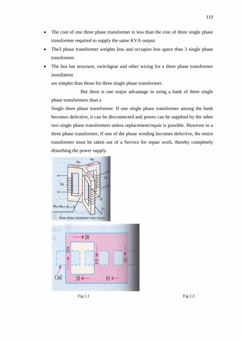
113
Contd…
· The cost of one three phase transformer is less than the cost of three single phase
transformer required to supply the same KVA output.
· The3 phase transformer weights less and occupies less space than 3 single phase
transformer.
· The bus bar structure, switchgear and other wiring for a three phase transformer
installation
are simpler than those for three single phase transformer.
But there is one major advantage in using a bank of three single
phase transformers than a
Single three phase transformer. If one single phase transformer among the bank
becomes defective, it can be disconnected and power can be supplied by the other
two single phase transformers unless replacement/repair is possible. However in a
three phase transformer, If one of the phase winding becomes defective, the entire
transformer must be taken out of a Service for repair work, thereby completely
disturbing the power supply.
Fig.1.1 Fig.1.2
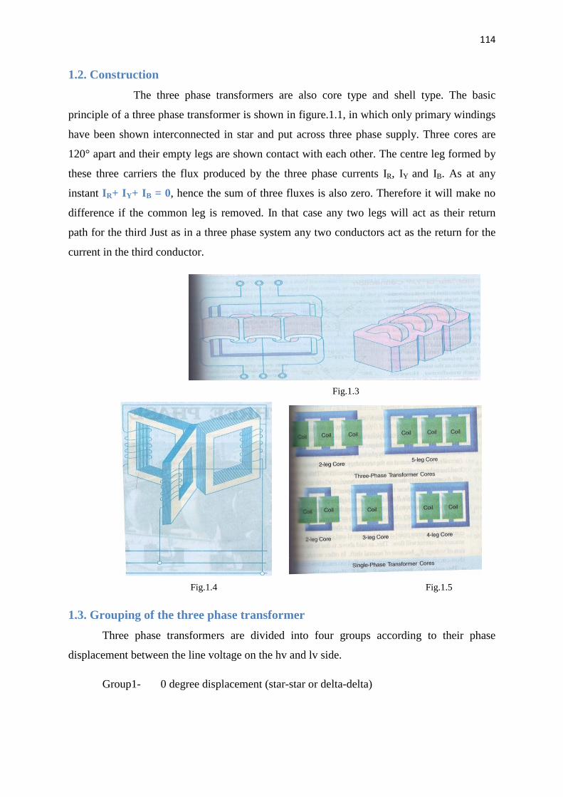
114
Contd…
1.2. Construction
The three phase transformers are also core type and shell type. The basic
principle of a three phase transformer is shown in figure.1.1, in which only primary windings
have been shown interconnected in star and put across three phase supply. Three cores are
120° apart and their empty legs are shown contact with each other. The centre leg formed by
these three carriers the flux produced by the three phase currents IR, IY and IB. As at any
instant IR+ IY+ IB = 0, hence the sum of three fluxes is also zero. Therefore it will make no
difference if the common leg is removed. In that case any two legs will act as their return
path for the third Just as in a three phase system any two conductors act as the return for the
current in the third conductor.
Fig.1.3
Fig.1.4 Fig.1.5
1.3. Grouping of the three phase transformer
Three phase transformers are divided into four groups according to their phase
displacement between the line voltage on the hv and lv side.
Group1- 0 degree displacement (star-star or delta-delta)

115
Contd…
Group2 - 180 degree displacement (star-star or delta-delta but the secondary is
reversed)
Group3- +30 degree displacement (sta-delta)
Group4- -30 degree displacement (delta-star)
Thus a connection Yd11 gives the following information
Y indicates that hv is connected in star
d indicates that lv is connected in delta
11 indicate that lv line voltage lags hv line voltage by +30 degree. (Measured from hv
phasor in anticlockwise direction).
The phase difference between the hv & lv windings for different types of connection
can be represented by comparing it with the hour hand of the clock. When the hour hand of
the clock is at 12 O’clock position, the phase displacement is zero. Similarly
Position of hour hand of clock Phase displacement
0 0°
11 +30°
1 -30°
6 180°
Depending on the phase displacement of the voltages of hv (high voltage) & lv (low
voltage) sides, transformers are classified into groups called “Vector group”. Transformer
having the same phase displacement between the hv & lv sides are classified into one same
group. For successful parallel operation of transformers, they should belong to the same
vector group. For example, a star-star connected three phase transformer can be paralleled
with another three phase transformer whose windings are either star-star connected or delta-
delta connected. A star-star connected transformer cannot be paralleled with another star-
delta connected transformer as this may result in short-circuiting of the secondary side.
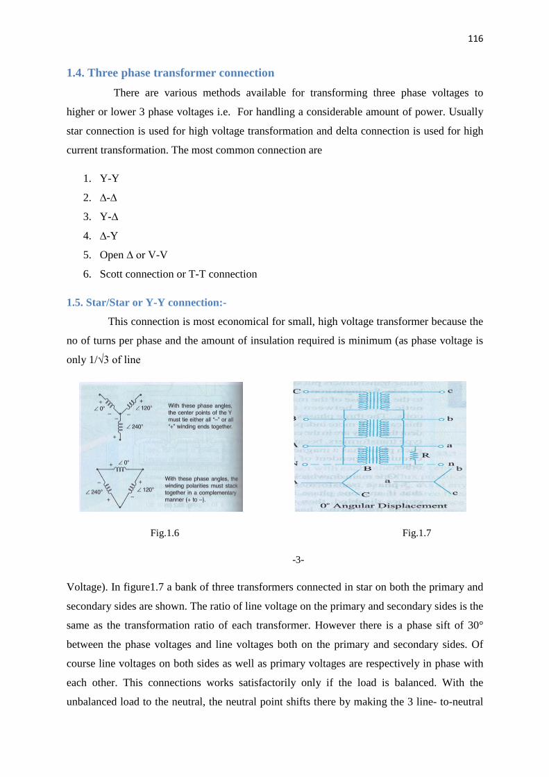
116
Contd…
1.4. Three phase transformer connection
There are various methods available for transforming three phase voltages to
higher or lower 3 phase voltages i.e. For handling a considerable amount of power. Usually
star connection is used for high voltage transformation and delta connection is used for high
current transformation. The most common connection are
1. Y-Y
2. ∆-∆
3. Y-∆
4. ∆-Y
5. Open ∆ or V-V
6. Scott connection or T-T connection
1.5. Star/Star or Y-Y connection:-
This connection is most economical for small, high voltage transformer because the
no of turns per phase and the amount of insulation required is minimum (as phase voltage is
only 1/√3 of line
Fig.1.6 Fig.1.7
-3-
Voltage). In figure1.7 a bank of three transformers connected in star on both the primary and
secondary sides are shown. The ratio of line voltage on the primary and secondary sides is the
same as the transformation ratio of each transformer. However there is a phase sift of 30°
between the phase voltages and line voltages both on the primary and secondary sides. Of
course line voltages on both sides as well as primary voltages are respectively in phase with
each other. This connections works satisfactorily only if the load is balanced. With the
unbalanced load to the neutral, the neutral point shifts there by making the 3 line- to-neutral

117
Contd…
(I.e. phase) voltages unequal. The effect of unbalanced loads can be illustrated by placing a
single load between phase (or coil) a and the neutral on secondary side. The power in the load
has to be supplied by primary phase (or coil) A. This primary coil A cannot supply the
required power because it is in series with primaries B and C whose secondaries are opened.
Under these condition the primary coils B and C act as very high impedances so that primary
coil A can obtain but very little current through them from the line. Hence secondary coil a
cannot supply appreciable power. In fact, a very low resistance approaching a short circuit
may be connected between point A and the neutral and only a very small amount of current
will flow. This, as said above, is due to the reduction of voltage Ean because of neutral shift.
In other words, under short-circuit condition, the neutral is pulled too much towards coil a.
This reduces Ean but increases Ebn & Ecn (however line voltage EAB, EBC,ECA are
unaffected). On the primary side, Ean will be practically reduced to zero whereas EBN & ECN
will rise to nearly full primary line voltage. This difficulty of shifting (or floating) neutral can
be obviated by connecting the primary neutral (shown dotted in the figure) back to the
generator so that primary coil A can take its required power from between its line and the
neutral. It should be noted that if a single phase load is connected between the lines a and b,
there will be a similar but less pronounced neutral sheet which results in an over voltage on
one or more transformers.
Another advantage of stabilizing the primary neutral by connecting it to neutral of the
generator is that it eliminates distortion in the secondary phase voltages. This is explained as
follows. For delivering a sine wave of voltage, it is necessary to have a sine wave of flux in
the core, but on account of the characteristics of iron, a sine wave flux requires a third
harmonic component in the exciting current. As the frequency of this component is thrice the
frequency of three circuit, at any given instant of time, it needs it tends to flow either towards
or away from the neutral point in all the three transformers. If the primary neutral is isolated
the triple frequency current cannot flow. Hence, the flux in the core cannot be a sine wave
and so the voltages are distorted. But if the primary neutral is earthed i.e. joined to the
generator neutral, then this provides a path for the triple frequency currents and e.m.fs and the
difficulty is overcome. Another way of avoiding this trouble of oscillating neutral is to
provide each of the transformers with a third or tertiary winding of relatively low KVA
rating. This tertiary winding connected in delta and provides a circuit in which the triple
frequency component of the magnetising current can flow (with an isolated neutral, it could
not). In this case a sine wave of voltage applied to the primary will result in a sine wave of

118
Contd…
phase voltage in the secondary. As said above, the advantage of this connection is that
insulation is stressed only to the extent of line to neutral voltage i.e. 58% of the line voltage.
1.6. Delta-Delta or ∆-∆ connection:-
This connection is economical for large, low voltage transformers in which insulation
problem is not so urgent, because it increases the number of turns/phase. The transformers
connection and voltage triangles are shown in fig 1.8 The ratio of transformation between
primary and secondary line voltage is exactly the same as that of each transformers. Further,
the secondary voltage triangle abc occupy the same relative position as the primary voltage
triangle ABC i.e. there is no angular displacement between the two. Moreover, there is no
internal phase shift between phase and line voltages on either side as was the case in Y-Y
connection. This connection has the following advantages:
-4-
Fig.1.8
1. As explained above, in order that the output voltage be sinusoidal, it is necessary
that the magnetising current of the transformer must contained a third harmonic component.
In this case third harmonic component of the magnetising current can flow in the ∆ connected
transformer primaries without flowing in the line wires. The three phases are 120° apart
which is 3X120°=360° with respect to the third harmonic, hence it merely circulates in the ∆.
Therefore the flux is sinusoidal which results in sinusoidal voltages.

119
Contd…
2. No difficulty is experienced from unbalanced loading as was the case in Y-Y
connection. The three phase voltages remain practically constant regardless of load
imbalance.
3. An added advantage of this connection is that if one transformer becomes disable,
the system can continue to operate in open delta or in V-V although with reduced available
capacity. The reduced capacity is 58% and not 66.7% of the normal value as explained in
Art.1.9.
1.7. Wye/Delta or Y-∆ connection:-
The main use of this connection is at the substation end of the transmission line
where the voltage is to be stepped down. The primary winding is Y connected with grounded
neutral as shown in fig1.9 the ratio between the secondary and primary line voltage is 1/√3
times the transformation ratio of each transformer. There is a 30° shift between the primary
and secondary line voltages which means that a Y-∆ transformer bank cannot be paralleled
with either a Y-Y and ∆-∆ bank. Also, a third harmonic current flows in the ∆ to provide a
sinusoidal flux.
Fig.1.9
1.8. Delta/Wye or ∆-Y connection:-
This connection is generally employed where it is necessary to step up the voltage as for
example at the beginning of high tension transmission system. The connection is show in fig1.10 the
neutral of the secondary is grounded for providing three phase four wire service. In recent years, these
connections has gained considerable popularity because it can be used to serve both the three phase
power equipment and single phase lighting circuit.
-5-

120
Contd…
This connection is not open to the objection of a floating neutral and voltage
distortion because the existence of a ∆ connection allows a path for the third harmonic
currents. It would be observed that the primary and secondary line voltages and line currents
are out of phase with each other by 30°. Because of this 30° shift it is impossible to parallel
such a bank with a ∆-∆ and Y-Y bank of transformers even though the voltage ratios are
correctly adjusted. The ratio of secondary to primary voltage is √3 times the transformation
ratio of each transformer.
Fig.1.10
Example 1.1. A 3 phase, 50 Hz transformer has a delta-connected primary and star connected
secondary, the line voltage being 22000 V and 400V respectively. The secondary has a star
connected balanced load at 0.8 power factor lagging. The line current on the primary side is
5A.Determine the current in each coil of the primary and in each secondary line. What is the
output of the transformer in KW ?
Solution : It sould be noted that in 3 phase tranformer, the phase tranformation ratio is equal
to the turn ratio but the terminal or line voltages depend upon the method of connection
employed. The delta/star connection is shown in figure 1.11 .
Phase voltage on primary side= 22000V
Phase voltage on secondary side= 400/√3
K=400/22000x√3 = 1/55√3
Primary phase current = 5/√3 A
Secondary phase current= (5/√3)/K =(5/√3)/(1/55√3) =275 A
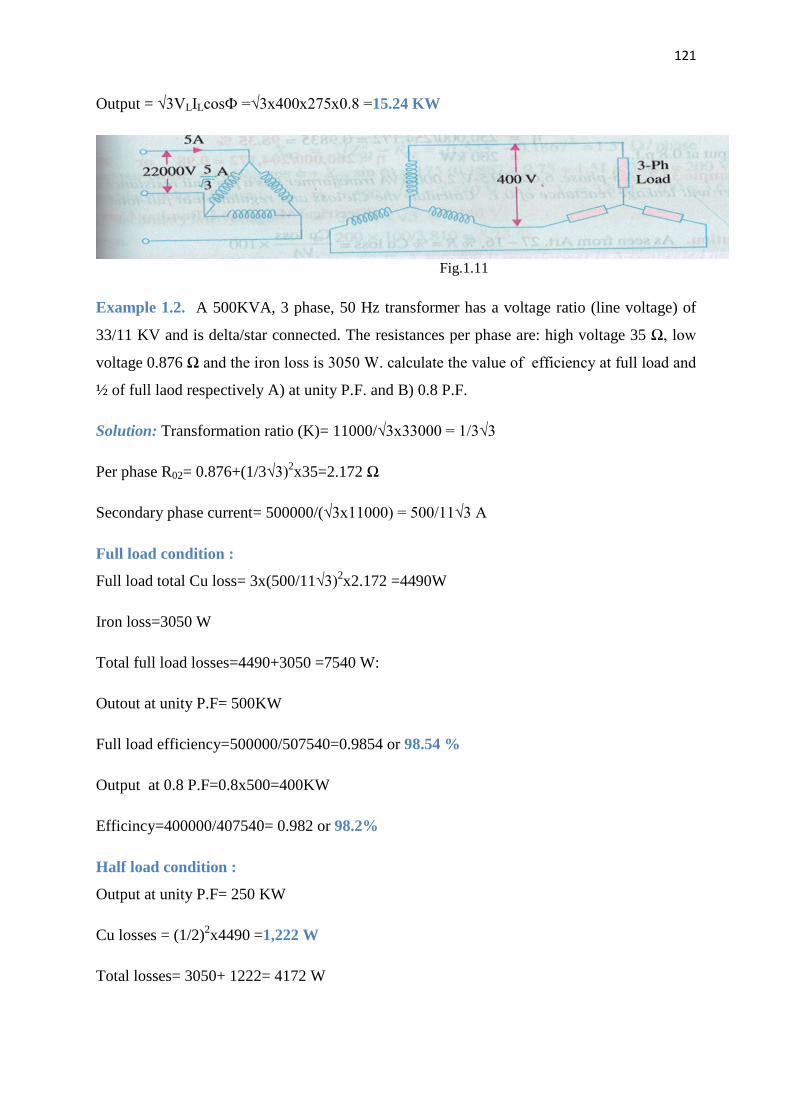
121
Contd…
Output = √3VLILcosФ =√3x400x275x0.8 =15.24 KW
Fig.1.11
Example 1.2. A 500KVA, 3 phase, 50 Hz transformer has a voltage ratio (line voltage) of
33/11 KV and is delta/star connected. The resistances per phase are: high voltage 35 Ω, low
voltage 0.876 Ω and the iron loss is 3050 W. calculate the value of efficiency at full load and
½ of full laod respectively A) at unity P.F. and B) 0.8 P.F.
Solution: Transformation ratio (K)= 11000/√3x33000 = 1/3√3
Per phase R02= 0.876+(1/3√3)2x35=2.172 Ω
Secondary phase current= 500000/(√3x11000) = 500/11√3 A
Full load condition :
Full load total Cu loss= 3x(500/11√3)2x2.172 =4490W
Iron loss=3050 W
Total full load losses=4490+3050 =7540 W:
Outout at unity P.F= 500KW
Full load efficiency=500000/507540=0.9854 or 98.54 %
Output at 0.8 P.F=0.8x500=400KW
Efficincy=400000/407540= 0.982 or 98.2%
Half load condition :
Output at unity P.F= 250 KW
Cu losses = (1/2)2x4490 =1,222 W
Total losses= 3050+ 1222= 4172 W
122
Contd…
Efficiency=250000/254172=0.9835 or 98.35%
Output at 0.8 P.F=200 KW
Efficiency= 200000/204172= 0.98 or 98%
1.9. Open- Delta or V-V Connection.
If one of the transformers of a ∆-∆ is removed and 3phase supply is connected to the
primaries as shown in Fig. 1.12, then three equal 3 phase valtages will be at the secondary
terminals on no load. This method of transforming 3-pahse power by means of only two
transformers is called the open -∆ or V-V connection.
It is employed:
1. When the three-phase load is too small to warrant the installation of full three phase
transformer bank.
2. When one of the transformers in a ∆-∆ bank is disabled, so that service is continued
although at reduced capacity, till the faulty transformers is repaired or a new one is
substituted.
3. When it is anticipated that in future the load will increase necessitating the closing of
open delta.
One important point to note is that the total load that can be carried by a V-V
bank is not two-third of the capacity of a ∆-∆ bank but it is only 57.7% of it. That is a
reduction of 15% (STRICTLY, 15.5%) from its normal rating. Suppose there is ∆-∆
bank of three 10-kVA transformers. When one transformer removed, then it runs in
V-V. The total rating of the transformer kVA rating but only 0.866 of it i.e.
20x0.866=17.32 (or 30x0.57=17.3kVA). The fact that the ratio of V- capacity to ∆-
capacity is 1/ (or nearly 58%) instead of 66.67 percent can be proved as
follows:
-7-

123
Contd…
Fig1.12
As seen from fig 1.13(a)
∆-∆ capacity = √3.VLIL=√3.VL (√3IS )=3 VL .IS
In Fig1.13 (b) it is obvious that when ∆-∆ bank becomes V-V bank, the secondary
line current IL becomes equal to the secondary phase current IS.
(V-V- capacity/∆-∆ capacity) = √3.VLIS / 3 VL .IS =1/√3=0.577 or 58%
(a) Fig1.13 (b)
It means that the 3-phase load which can be carried without exceeding the rating of
the transformers is 57.7 per cent of the original load rather than the expected 66.7%.It is
obvious from above that when one transformer is removed from a ∆-∆ bank.
1. The bank capacity is reduced from 30 kVA to 30X0.577=17.3KVA and
not to 20 kVA as might be tought off hand.
2. Only 86.6% of the rated capacity of the two remaining transformers is
avalible (i.e. 20X0.866=17.3kVA). In other words, ratio of operating
capacity to avalible capacity on an open -∆ is 0.866. This factor of 0.866 is
sometimes called the utility factor.
3. Each transformer will supply 57.7% of load and not 50% when operating
in V-V.
However, it is worth noting that if three transformers in a ∆-∆ bank are delivering
their rated load and one transformer is removed, the overload on each of the remaining
transformers is 73.2% because
(Total load in V-V)/ (VA/transformer) = √3.VLIS/ VLIS=√3=1.732

124
Contd…
This over-load may be carried temporarily but some provision must be made to
reduce the load if overheating and consequent breakdown of the remaining two transformers
is to be avoided.
The disadvantages of this connection are:
1. The average power factor at which the V-bank opeates is less than that
of the load, this power factor is actually 86.6% of the balanced load
power factor. Another significant point to note is that, except for a
balanced unity power factor load, the two transformers in the V-V
bank operate at different power factors.
2. Secondary terminal voltages tend to become unbalanced to a great
extent when the load is increased, this happens even when the load is
perfectly balanced.
It may, however be noted that if two transformers are operating in V-V
and loaded to rated capacity in the above example, to 17.3kVA, the
addition of a third transformer increases the total capacity by √3 or
173.2% (i.e to 30kVA). it means that for an increase in cost of 50% for
the third transformer. The increase in capacity is 73.2%when
converting from a V-V system to a ∆-∆ system.
1.10. Power supplied by V-V connection:
When a V-V bank of two transformer supplies a balanced 3-phae load of power factor
cos ф, then one transformer operates at a p.f. of cos(300- ф) and the other at cos(300+ ф).
Consequently, the two transformers will not have the same voltage regulation.
P1= KVA X cos (300- ф) And P2= KVA X cos (300+ф)
i) When ф=0 i.e. load p.f. =1
Each transformer will have a p.f. = cos300 =0.866
ii) When ф=300 i.e. load p.f. =0.866,
In this case, one transformer has a p.f. of cos (300 - 300) = 1 and the other of cos (300 +300) =
0.866
iii) ) when ф=600 i.e. load p.f.=0.5,

125
Contd…
In this case, one transformer has a p.f. of cos (300 - 600) = cos (-300 )=0.866 and the other of
cos (300 +600) = cos (900 )=0. It means that one of the transformers will not supply any load
whereas the other having a power factor of 0.866 will supply the entire load.
Example 1.3. What should be the kVA rating of each transformer in a V – V bank when the
3 – phase balanced load is 40 kVA? If a third similar transformer is connected for operation
,what is the rated capacity? What percentage increase in rating is affected in this way?
Solution. As pointed out earlier, the kVA rating of each transformer has to be 15% greater.
kVA / transformer = ( 40 / 2) x 1.15 = 23
Δ – Δ bank rating = 23 x 3 = 69; Increase = [(69 – 40) / 40] x 100 = 72.5 %.
1.11. Scott Connection or T-T connection:
This is a connection by which 3-phase to 3-phase transformation is accomplished with
the help of two transformers as shown in Fig. 1.14. Since it was first proposed by Charles F.
Scott, it is frequently referred to as Scott connection. This connection can also be used for 3-
phase to 2-phase transformation as explained.
One of the transformers has centre taps both on the primary and secondary ending
(Fig1.14) and is known as the main transformer. It forms the horizontal member of the
connection (Fig.1.15).
The other transformer has a 0.866 tap and is known as teaser transformer. One end
of both the primary and secondary of the teaser transformer is joined to the centre taps on
both primary and secondary of the main transformer respectively as shown in Fig. 1.15(a) .
The other end A of the teaser primary and the two ends B and C of the main transformer
primary are connected to the 3-phase supply.
The voltage diagram is shown in Fig 1.15(a) where the 3-pahse supply line voltage is
assumed to be 100 V and a transformation ratio of unity. For understanding as to how 3-
phase transformation results from this arrangement, it is desirable to think of the primary and
secondary vector voltage forming geometrical Ts’ (from which this connection gets its
name).

126
Contd…
Fig1.14
In the primary voltage T of Fig 1.15(a) EDC and EDB are each 50V and differ in phase
by 1800 because both coils DB and DC are on the same magnetic circuit and are connected in
opposition. Each side of the equilateral triangle represents 100 V. The voltage EDA being the
altitude of the equilateral triangle is equal to (√3/2) X100=86.6 V and lags behind the voltage
across the main by 900. The same relation holds good in the secondary winding so that abc is
a symmetrical 3-phase system.
Fig.1.15
With reference to the secondary voltage triangle of Fig. 1.15(b),it is should be noted
that for a load of unity power factor, current Idb lags behind voltage Edb by 300 and Idb leads
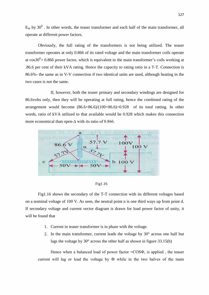
127
Contd…
Edc by 300 . In other words, the teaser transformer and each half of the main transformer, all
operate at different power factors.
Obviously, the full rating of the transformers is not being utilized. The teaser
transformer operates at only 0.866 of its rated voltage and the main transformer coils operate
at cos300= 0.866 power factor, which is equivalent to the main transformer’s coils working at
.86.6 per cent of their kVA rating. Hence the capacity to rating ratio in a T-T. Connection is
86.6%- the same as in V-V connection if two identical units are used, although heating in the
two cases is not the same.
If, however, both the teaser primary and secondary windings are designed for
86.6volts only, then they will be operating at full rating, hence the combined rating of the
arrangement would become (86.6+86.6)/(100+86.6)=0.928 of its total ratting. In other
words, ratio of kVA utilized to that available would be 0.928 which makes this connection
more economical than open-∆ with its ratio of 0.866.
Fig1.16
Fig1.16 shows the secondary of the T-T connection with its different voltages based
on a nominal voltage of 100 V. As seen, the neutral point n is one third ways up from point d.
If secondary voltage and current vector diagram is drawn for load power factor of unity, it
will be found that
1. Current in teaser transformer is in phase with the voltage.
2. In the main transformer, current leads the voltage by 30° across one half but
lags the voltage by 30° across the other half as shown in figure 33.15(b)
Hence when a balanced load of power factor =COSФ, is applied , the teaser
current will lag or lead the voltage by Ф while in the two halves of the main
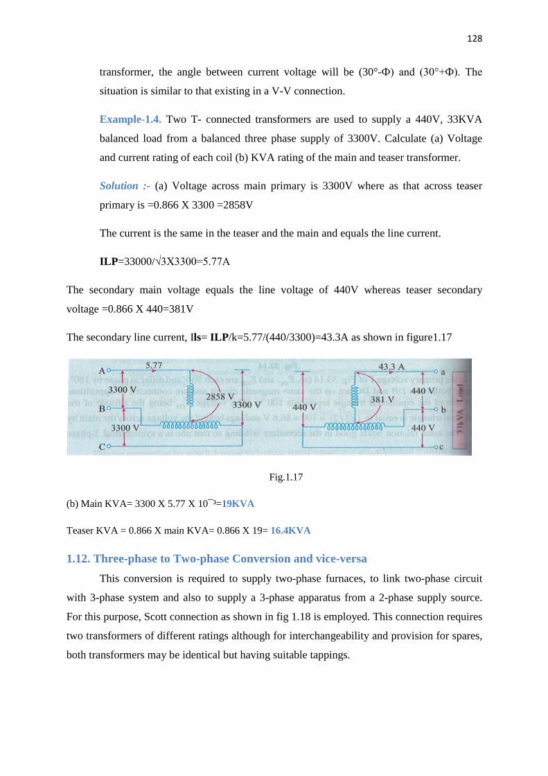
128
Contd…
transformer, the angle between current voltage will be (30°-Ф) and (30°+Ф). The
situation is similar to that existing in a V-V connection.
Example-1.4. Two T- connected transformers are used to supply a 440V, 33KVA
balanced load from a balanced three phase supply of 3300V. Calculate (a) Voltage
and current rating of each coil (b) KVA rating of the main and teaser transformer.
Solution :- (a) Voltage across main primary is 3300V where as that across teaser
primary is =0.866 X 3300 =2858V
The current is the same in the teaser and the main and equals the line current.
ILP=33000/√3X3300=5.77A
The secondary main voltage equals the line voltage of 440V whereas teaser secondary
voltage =0.866 X 440=381V
The secondary line current, Ils= ILP/k=5.77/(440/3300)=43.3A as shown in figure1.17
Fig.1.17
(b) Main KVA= 3300 X 5.77 X 10¯³=19KVA
Teaser KVA = 0.866 X main KVA= 0.866 X 19= 16.4KVA
1.12. Three-phase to Two-phase Conversion and vice-versa
This conversion is required to supply two-phase furnaces, to link two-phase circuit
with 3-phase system and also to supply a 3-phase apparatus from a 2-phase supply source.
For this purpose, Scott connection as shown in fig 1.18 is employed. This connection requires
two transformers of different ratings although for interchangeability and provision for spares,
both transformers may be identical but having suitable tappings.

129
Contd…
Fig1.18 Fig.1.19
If, in the secondaries of Fig.1.15 (b), points c and d are connected as shown in
Fig.1.19 (b), then a 2-phase, 3-wire system is obtained. The voltage Edc is 86.6 V but Ecb =
100V, hence the resulting 2-phase voltages will be unequal. However, as shown in Fig.1.20
(a) if the3-phase line is connected to point A1, such that DA1 represents 86.6%of the teaser
primary turns (which are the same as that of main primary), then this will increase the
volts/turn in the ratio of 100:86.6, because now 86.6 volts are applied across 86.6 percent of
turns and not 100% turns. In other words, this will make volts/turn the same both in primary
of the teaser and that of the main transformers. If the secondaries are of both the
transformers have the same number of turns, then the secondary voltage will be equal
magnitude as shown, thus resulting in a 2-phase, 3-wire system.
Fig1.20
Consider the same connection drawn slightly differently as in fig.1.21. The primary
of the main transformer having N1 turns is connected between terminals CB of a 3-phse
supply. If supply line voltage is V. then obviously VAB=VBC=VCA= V but voltage between A
and D is V x √3/2. As said above, the number of turns between A and D should be (√3/2)N1
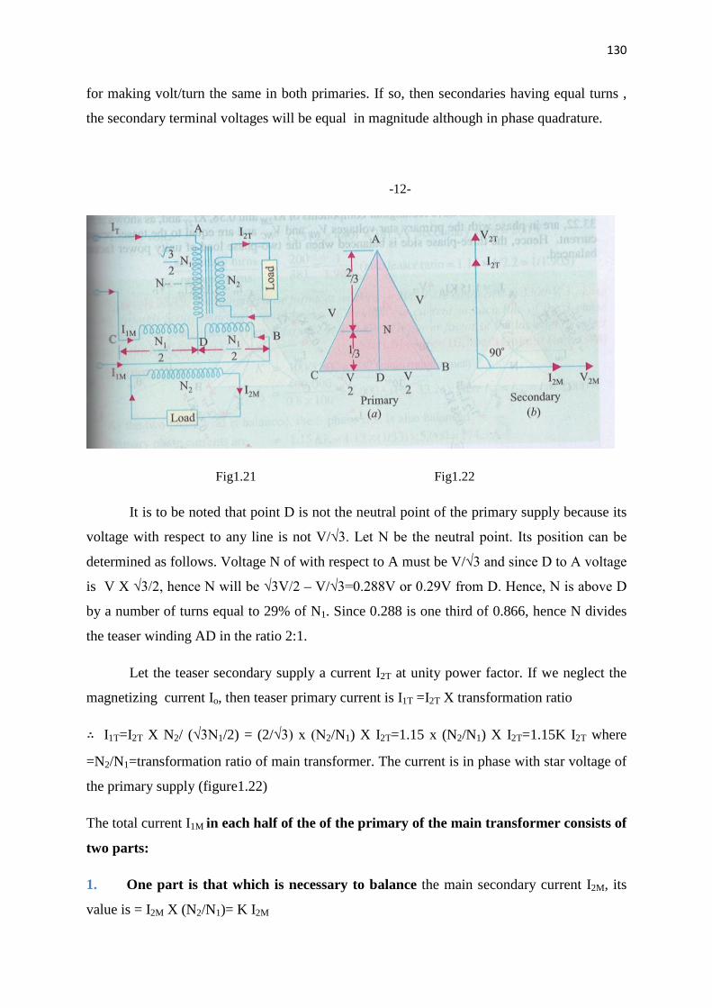
130
Contd…
for making volt/turn the same in both primaries. If so, then secondaries having equal turns ,
the secondary terminal voltages will be equal in magnitude although in phase quadrature.
-12-
Fig1.21 Fig1.22
It is to be noted that point D is not the neutral point of the primary supply because its
voltage with respect to any line is not V/√3. Let N be the neutral point. Its position can be
determined as follows. Voltage N of with respect to A must be V/√3 and since D to A voltage
is V X √3/2, hence N will be √3V/2 – V/√3=0.288V or 0.29V from D. Hence, N is above D
by a number of turns equal to 29% of N1. Since 0.288 is one third of 0.866, hence N divides
the teaser winding AD in the ratio 2:1.
Let the teaser secondary supply a current I2T at unity power factor. If we neglect the
magnetizing current Io, then teaser primary current is I1T =I2T X transformation ratio
I1T=I2T X N2/ (√3N1/2) = (2/√3) x (N2/N1) X I2T=1.15 x (N2/N1) X I2T=1.15K I2T where
=N2/N1=transformation ratio of main transformer. The current is in phase with star voltage of
the primary supply (figure1.22)
The total current I1M in each half of the of the primary of the main transformer consists of
two parts:
1. One part is that which is necessary to balance the main secondary current I2M, its
value is = I2M X (N2/N1)= K I2M

131
Contd…
Fig1.23
2. The second part is equal to one half of the teaser primary current i.e. 0.5 I1T. This is so
because the main transformer primary forms a return path for the teaser primary current
which divides itself into two halves at mid point D in either direction. The value of each half
is =0.5 I1T=1.15K I2T/2= 0.58 K I2T.
Hence the current in the lines B and C are obtained vectorially as shown in
fig.1.23. It should be noted that as the two halves of the teaser primary current flow in
opposite directions from point D, they have no magnetic effect on the core and play no part at
all in balancing the secondary ampere-turns of the main transformer.
The line currents thus have rectangular components of K I2M and 0.58 K I2T and
as shown in fig. 1.23, are in phase with primary star voltages VNB and VNC and are equal to
the teaser primary current. Hence, the three phase side is balanced when the two phase load
of unity power factor is balanced.
132
Contd…
Fig1.24
Figure 1.24(a) illustrates the condition corresponding to a balanced two phase
load at a lagging power factor of 0.866. The construction is the same as in figure 1.23. it will
be seen that the three- phase side is again balanced. But under these conditions the main
transformer rating is 15%greater than that of the teaser, because its voltage is 15% greater
although its current is the same.
Hence, we conclude that if the load is balanced on one side, it would always be
balanced on the other side.
The conditions corresponding to an unbalanced two-phase load having different currents and
power factors are shown in figure 1.24(b). The geometrical construction is similar to those
explained in figure 1.23 and 1.24(a).
Summarizing the above we have:
1. Teaser transformer primary has √3/2 times the turns of main primary. But volt/turn is
the same. Their secondaries have the same turns which result in equal secondary terminal
voltages.
2. If main primary has N1 turns and main secondary has N2 turns, then main
transformation ratio is N2/ N1. However, the transformation ratio of teaser is N2/ (√3 N1/2)
=1.15 N2/ N1=1.15K.
3. If the load is balanced on one side, it is balanced on the other side as well.
4. Under balanced load conditions, main transformer rating is 15% greater than that of the
teaser.
5. The currents in either of the two halves of main primary are the vector sum of K I2M and
0.58K I2T(or 0.5 I1T)
Example 1.5. Two transformers are required for Scott connection operating from a 440V,
three phase supply for supplying two single phase furnaces at 200V on the two phase side. If
the total output is 150KVA, calculate the secondary to primary turn ratio and the winding
currents of each transformer.

133
Contd…
Soln: - main transformer
Primary volts= 440V secondary volts=200V N2/ N1=200/440=1/2.2
Secondary current = 150000/2 X 200=375 A
Primary current =375 X 1/2.2=197A
Teaser transformer
Primary volts= (√3/2 X 440) =381V: Secondary volts =200V
Secondary turns /primary turns =200/381=0.52(also teaser ratio =1.15 X
1/2.2=0.52).
1.13. Parallel operation of three phase transformer
Transformers are said to be connected in parallel when their primary windings are
connected to a common voltage supplier and their secondary windings are connected to a
common load.
1.14. Reasons for parallel operation
1. Extension of loads - for large loads it may be impracticable or uneconomical to have
a single large transformer.
2. Capacity to spare – in substations the total load required may be supplied by an
appropriate no of transformers of standard size. This reduces the spare capacity of the
substation.
3. Future extension - there scope of future extension of a substation to supply a load
beyond the capacity of the transformers already installed.
4. If there is a breakdown of transformer in system of transformers connected in
parallel, there is no interruption of power supply for essential service. Similarly when a
transformer is taken out of service for its maintenance and inspection the continuity of supply
is maintained.

134
Contd…
1.15. Condition for parallel operation
All the condition which applied to the parallel operation of single phase transformer
also is applied to the parallel running of three phase transformer but with the following
addition
1. The voltage ratio must refer to the terminal voltage of primary and secondary. It is
obvious that this ratio may not be equal to the ratio of the number of turns per phase. For
example, if V1, V2 are the primary and secondary terminal voltages, then for Y/∆ connection
the turn ratio is V2/ ( V1/√3) = √3V2/ V1.
2. The phase displacement between primary and secondary voltages must be the same
for all transformers which are to be connected for parallel operation.
3. Phase sequence must be the same.
4. All the three transformers in the three phase transformer bank will be of the same
construction either core or shell.
Note 1: IN dealing with three phase transformer calculation are made for one phase only. The
value of equivalent impedance used is the impedance per phase referred to secondary.
2. In case the impedance of primary and secondary windings are given separately then
primary impedance must be referred to secondary by multiplying it with (transformation
ratio) .
3. For Y/∆ or ∆/ Y transformers should be remembered that the voltage ratio as given in the
question is referred to terminal voltages and are quite different from turn ratio.
1.16. Tap changers in transformers
The modern equipments, utilising electrical energy are design to operate satisfactorily at one
voltage level. It is therefore of paramount importance to keep the consumers’ terminal
voltage, within the prescribed limits. The transformer output voltage and hence the
consumers’ terminal voltage, can be controlled by providing taps either on the primary or on
the secondary.
The principle of regulating the secondary output voltage is based on changing the
number of turns in the secondary quantities. V2= (N2/ N1) X V1.

135
Contd…
If the tap changer is design to operate, when the transformer is out of circuit, it is then
called off-load (or no load) tap changer. A tap changer design to operate with the transformer
in the circuit is called on load tap changer.
1.17. No load (or off-load) Tap changer
This tap changer is used for seasonal voltage variation. And elementary form of no
load tap changer is illustrated in figure.1.25. It has six studs mark from one to six. The
winding is tapped at six points equal to the number of studs. The tapping leads are connected
to six correspondingly marks stationary studs arranged in circle. The face plate carrying the
six studs, can be mounted anywhere on the transformer, say on the yoke or any other
convenient place. The rotatable arm R can be rotated by means of hand wheel, from outside
the tank.
If the winding is tapped at 2.5% intervals, than with the rotatable arm R
· At studs 1,2: Full winding is in circuit
· At studs 2,3: 97.5% of the winding is in circuit
· At studs 3,4: 95% of the winding is in circuit
· At studs 4,5: 92.5% of the winding is in circuit
· At studs 5,6: 90% of the winding is in circuit
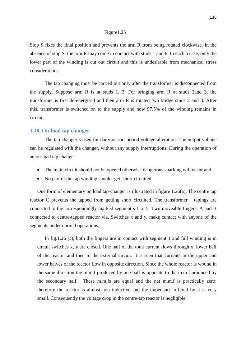
136
Contd…
Figure1.25
Stop S fixes the final position and prevents the arm R from being rotated clockwise. In the
absence of stop S, the arm R may come in contact with studs 1 and 6. In such a case, only the
lower part of the winding is cut out circuit and this is undesirable from mechanical stress
considerations.
The tap changing must be carried out only after the transformer is disconnected from
the supply. Suppose arm R is at studs 1, 2. For bringing arm R at studs 2and 3, the
transformer is first de-energised and then arm R is rotated two bridge studs 2 and 3. After
this, transformer is switched on to the supply and now 97.5% of the winding remains in
circuit.
1.18. On-load tap changer
The tap changer s used for daily or sort period voltage alteration. The output voltage
can be regulated with the changer, without any supply interruptions. During the operation of
an on-load tap changer.
· The main circuit should not be opened otherwise dangerous sparking will occur and
· No part of the tap winding should get short circuited
One form of elementary on load tap-changer is illustrated in figure 1.26(a). The centre tap
reactor C prevents the tapped from getting short circuited. The transformer tapings are
connected to the correspondingly marked segment s 1 to 5. Two moveable fingers, A and B
connected to centre-tapped reactor via. Switches x and y, make contact with anyone of the
segments under normal operations.
In fig.1.26 (a), both the fingers are in contact with segment 1 and full winding is in
circuit switches x, y are closed. One half of the total current flows through x, lower half
of the reactor and then to the external circuit. It is seen that currents in the upper and
lower halves of the reactor flow in opposite direction. Since the whole reactor is wound in
the same direction the m.m.f produced by one half is opposite to the m.m.f produced by
the secondary half. These m.m.fs are equal and the net m.m.f is practically zero:
therefore the reactor is almost non inductive and the impedance offered by it is very
small. Consequently the voltage drop in the centre-tap reactor is negligible.

137
Contd…
When a change in voltage is required the finger A and B can be brought to segment
to, by adopting the following sequence of operations.
· Open switch y figure 1.26 (b1). The entire current must now flow through the
lower half of the reactor. It therefore, becomes highly inductive and there is a
large voltage drop. It should be noted that the rector must be designed to handle
full load current, momentarily.
· The finger B carries no current and can therefore, be moved to segment 2, without
any sparking (figure 1.26(b2)).
· Close switch Y figure1.26 (b3) the transformer winding between taps 1 and 2 gets
connected across the reactor. Since the impedance offered by the reactor is high
for a current flowing in only one direction, the local circulating current flowing
through the reactor and tapped winding is quite small. In this manner, the reactor
prevents the tapped winding from getting short circuited. The terminal voltage
will be mid-way between the potentials of tappings 1 and 2.
· Open switch x: The entire currents start flowing through the upper half of the
reactor, manifested by large voltage drop, fig.1.26 (b4).
· Move the finger A from segment 1 to segment 2 and then close switch x: The
winding between taps 1 and 2 is therefore completely out of circuit, fig. 1.26(b5).
If further change in voltage is required, the above sequence of operations is
repeated.
· For large power transformers the switches x and y may be circuit breakers.
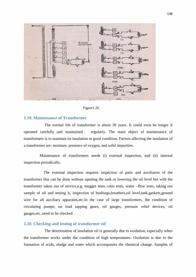
138
Contd…
Figure1.26
1.19. Maintenance of Transformer
The normal life of transformer is about 30 years. It could even be longer if
operated carefully and maintained regularly. The main object of maintenance of
transformers is to maintain its insulation in good condition. Factors affecting the insulation of
a transformer are: moisture, presence of oxygen, and solid impurities.
Maintenance of transformers needs (i) external inspection, and (ii) internal
inspection periodically.
The external inspection requires inspection of parts and auxiliaries of the
transformer that can be done without opening the tank or lowering the oil level but with the
transformer taken out of service,e.g. megger tests, ratio tests, water –flow tests, taking out
sample of oil and testing it, inspection of bushings,breathers,oil level,tank,gaskets,ground
wire for all auxiliary apparatus,etc.In the case of large transformers, the condition of
circulating pumps, on load tapping gears, oil gauges, pressure relief devices, oil
gauges,etc.,need to be checked.
1.20. Checking and testing of transformer oil
The deterioration of insulation oil is generally due to oxidation, especially when
the transformer works under the condition of high temperatures. Oxidation is due to the
formation of acids, sludge and water which accompanies the chemical change. Samples of

139
Contd…
transformer oil are taken out carefully and tested for colour and odour. Cloudiness in oil may
be due to suspended moisture or suspended solid matter. Dark brown colour may indicate
dissolved asphalt, green colour dissolved copper compounds; and acid smell indicates the
presence of volatile acids.
The oil samples may be tested as follows:
(a) The dielectric strength of oil should be tested as per IS: 335 – 1953.The oil should
withstand the test voltage of at least 30kV for one minute without breakdown.
(b) Cracle test for free water should be performed as per IS: 335 – 1953.The test is only
qualitative.
(c) The acidity of oil should be determined as per IS: 1866 – 1961.
(d) Sludge test: The traces of solid matter in oil samples may be examined as per IS: 1866
– 1961.
1.21. Insulation resistance
The insulation resistance is measured by megger test along with the
temperature. This is because the insulation resistance in megohms gets reduced to nearly half
for every 100c temperature rise. The insulation resistance should not be less than two
megohms for each 1000 v of operating voltage.
1.22. Internal inspection of Transformer
Take samples of oil from top and bottom for testing: Lower oil in transformer. Check inside
bushings, brackets, HV, LV windings for damage insulation; check connections, ground of
core, insulation condition of various parts, and inside condition. An inspection schedule
should be drawn for checks monthly, quarterly and yearly inspection.
1.23. Maintenance schedule
Every hour: Check temperature of oil, windings, ambient, load & voltage. Adjust load to
keep the temperature rise within a permissible limit.
Daily: (a) Check oil level; if low, fill in dry oil.
(b) Check the colour of the silica gel in the breather. Colour should be blue. If the
colour of the silica gel becomes pink replace them.
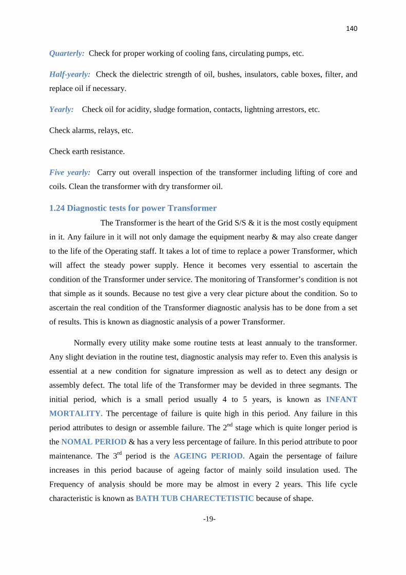
140
Contd…
Quarterly: Check for proper working of cooling fans, circulating pumps, etc.
Half-yearly: Check the dielectric strength of oil, bushes, insulators, cable boxes, filter, and
replace oil if necessary.
Yearly: Check oil for acidity, sludge formation, contacts, lightning arrestors, etc.
Check alarms, relays, etc.
Check earth resistance.
Five yearly: Carry out overall inspection of the transformer including lifting of core and
coils. Clean the transformer with dry transformer oil.
1.24 Diagnostic tests for power Transformer
The Transformer is the heart of the Grid S/S & it is the most costly equipment
in it. Any failure in it will not only damage the equipment nearby & may also create danger
to the life of the Operating staff. It takes a lot of time to replace a power Transformer, which
will affect the steady power supply. Hence it becomes very essential to ascertain the
condition of the Transformer under service. The monitoring of Transformer’s condition is not
that simple as it sounds. Because no test give a very clear picture about the condition. So to
ascertain the real condition of the Transformer diagnostic analysis has to be done from a set
of results. This is known as diagnostic analysis of a power Transformer.
Normally every utility make some routine tests at least annualy to the transformer.
Any slight deviation in the routine test, diagnostic analysis may refer to. Even this analysis is
essential at a new condition for signature impression as well as to detect any design or
assembly defect. The total life of the Transformer may be devided in three segmants. The
initial period, which is a small period usually 4 to 5 years, is known as INFANT
MORTALITY. The percentage of failure is quite high in this period. Any failure in this
period attributes to design or assemble failure. The 2nd stage which is quite longer period is
the NOMAL PERIOD & has a very less percentage of failure. In this period attribute to poor
maintenance. The 3rd period is the AGEING PERIOD. Again the persentage of failure
increases in this period bacause of ageing factor of mainly soild insulation used. The
Frequency of analysis should be more may be almost in every 2 years. This life cycle
characteristic is known as BATH TUB CHARECTETISTIC because of shape.
-19-
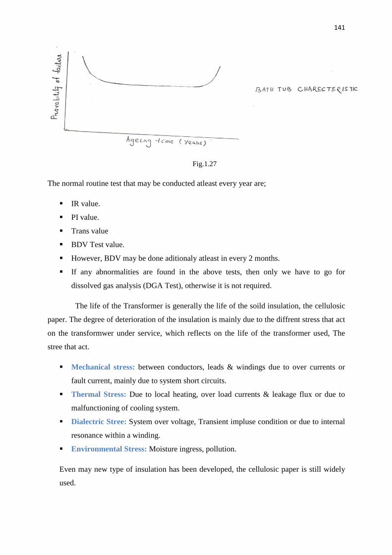
141
Contd…
Fig.1.27
The normal routine test that may be conducted atleast every year are;
§ IR value.
§ PI value.
§ Trans value
§ BDV Test value.
§ However, BDV may be done aditionaly atleast in every 2 months.
§ If any abnormalities are found in the above tests, then only we have to go for
dissolved gas analysis (DGA Test), otherwise it is not required.
The life of the Transformer is generally the life of the soild insulation, the cellulosic
paper. The degree of deterioration of the insulation is mainly due to the diffrent stress that act
on the transformwer under service, which reflects on the life of the transformer used, The
stree that act.
§ Mechanical stress: between conductors, leads & windings due to over currents or
fault current, mainly due to system short circuits.
§ Thermal Stress: Due to local heating, over load currents & leakage flux or due to
malfunctioning of cooling system.
§ Dialectric Stree: System over voltage, Transient impluse condition or due to internal
resonance within a winding.
§ Environmental Stress: Moisture ingress, pollution.
Even may new type of insulation has been developed, the cellulosic paper is still widely
used.
142
Contd…
The rising temperature in presence of moisture & oxygen accelerate the aging
process of the soild insulation, For a example, the paper with 2% moisture ages three
times taster then 1% moisture & 30 times to 3% moisture content. The degradation
product from oil oxidation, such as peroxides & water soluble acid absorbs in paper &
makes it brittle & low strength oxycellulose. The oxidation gradully deplets the natural
oxidation inhibitors present in naphthalenic oil & products are acid, ketones, peroxides,
soap, and aldehyds. This causes colloidal contamination in the oil which form
hydrocorbon which again polymerisis to form partly conduting sludge & get deposited on
the windings thus it makes heat transfer more diffcult & oxidation become more faster
due to rise of temperture, So it is conclusive that presence of moisture & oxygen in oil or
paper is the main culprit to reduce life of the transformer. The routine test must be
conducted regularly to know the presence of the moisture & weather it is within the limit
or not. If the value is low then there is no problem othewise we have to go for further
analysis regrading the presence of moisture & other conducting gaese & where it is
present (whether in oil or in paper or in both).A accordingly steps will be taken. The
oxidations also accelerate due to partial discharge.
By now our stand is more clear that;
§ We want to know whether any moisture or any conducting soluble gas or
conducting particulars present in the insulation.
§ If present not within limit then it is essential to know where it is and in which
formand how to separate it out & to increase the life period.
§ We should not allow to increase the moisture content in oil and if however it has
entered then it is assentail to knwo to what level the damage has been taken place.
So that we can decrease the effect to certain level and increase the life of our
transformer.
1.25. Routine test
(1) IR value:
It is simlpy the insulation resistance of the insulating materials i.e. paper & oil in
combination, A DC petential is applied usally 5 KV between diffrent windings, between
winding & tank of the transformer. Earlier, the value was noted after allowing the current for
15 sec. But now a day value is noted after 1 min. As the real values can be known only after
allowing the current for certain time. What should be the IR Value? It is a real debate. It
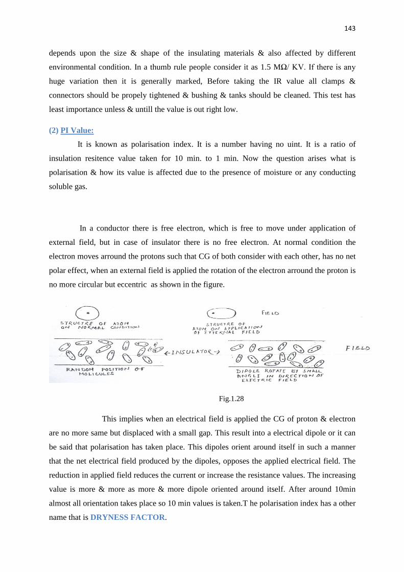
143
Contd…
depends upon the size & shape of the insulating materials & also affected by different
environmental condition. In a thumb rule people consider it as 1.5 MΩ/ KV. If there is any
huge variation then it is generally marked, Before taking the IR value all clamps &
connectors should be propely tightened & bushing & tanks should be cleaned. This test has
least importance unless & untill the value is out right low.
(2) PI Value:
It is known as polarisation index. It is a number having no uint. It is a ratio of
insulation resitence value taken for 10 min. to 1 min. Now the question arises what is
polarisation & how its value is affected due to the presence of moisture or any conducting
soluble gas.
In a conductor there is free electron, which is free to move under application of
external field, but in case of insulator there is no free electron. At normal condition the
electron moves arround the protons such that CG of both consider with each other, has no net
polar effect, when an external field is applied the rotation of the electron arround the proton is
no more circular but eccentric as shown in the figure.
Fig.1.28
This implies when an electrical field is applied the CG of proton & electron
are no more same but displaced with a small gap. This result into a electrical dipole or it can
be said that polarisation has taken place. This dipoles orient around itself in such a manner
that the net electrical field produced by the dipoles, opposes the applied electrical field. The
reduction in applied field reduces the current or increase the resistance values. The increasing
value is more & more as more & more dipole oriented around itself. After around 10min
almost all orientation takes place so 10 min values is taken.T he polarisation index has a other
name that is DRYNESS FACTOR.
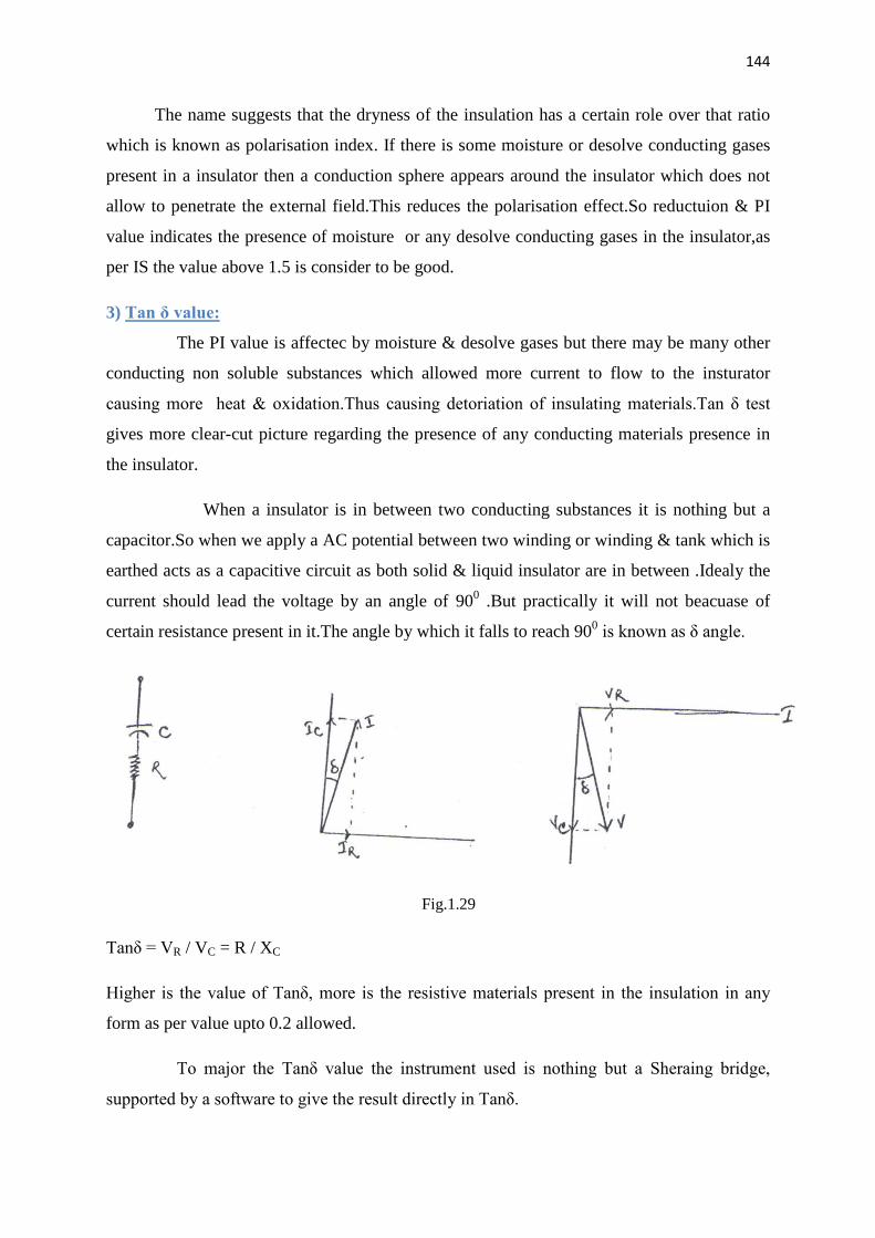
144
Contd…
The name suggests that the dryness of the insulation has a certain role over that ratio
which is known as polarisation index. If there is some moisture or desolve conducting gases
present in a insulator then a conduction sphere appears around the insulator which does not
allow to penetrate the external field.This reduces the polarisation effect.So reductuion & PI
value indicates the presence of moisture or any desolve conducting gases in the insulator,as
per IS the value above 1.5 is consider to be good.
3) Tan δ value:
The PI value is affectec by moisture & desolve gases but there may be many other
conducting non soluble substances which allowed more current to flow to the insturator
causing more heat & oxidation.Thus causing detoriation of insulating materials.Tan δ test
gives more clear-cut picture regarding the presence of any conducting materials presence in
the insulator.
When a insulator is in between two conducting substances it is nothing but a
capacitor.So when we apply a AC potential between two winding or winding & tank which is
earthed acts as a capacitive circuit as both solid & liquid insulator are in between .Idealy the
current should lead the voltage by an angle of 900 .But practically it will not beacuase of
certain resistance present in it.The angle by which it falls to reach 900 is known as δ angle.
Fig.1.29
Tanδ = VR / VC = R / XC
Higher is the value of Tanδ, more is the resistive materials present in the insulation in any
form as per value upto 0.2 allowed.
To major the Tanδ value the instrument used is nothing but a Sheraing bridge,
supported by a software to give the result directly in Tanδ.
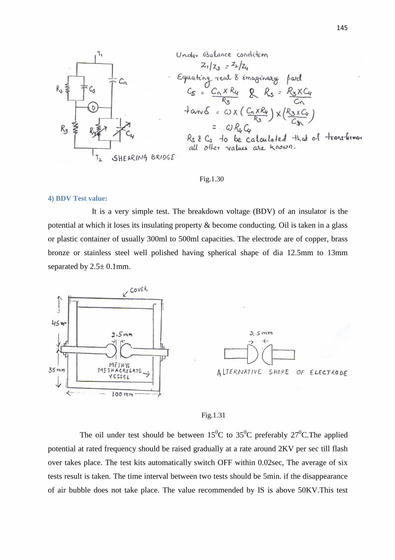
145
Contd…
Fig.1.30
4) BDV Test value:
It is a very simple test. The breakdown voltage (BDV) of an insulator is the
potential at which it loses its insulating property & become conducting. Oil is taken in a glass
or plastic container of usually 300ml to 500ml capacities. The electrode are of copper, brass
bronze or stainless steel well polished having spherical shape of dia 12.5mm to 13mm
separated by 2.5± 0.1mm.
Fig.1.31
The oil under test should be between 150C to 350C preferably 270C.The applied
potential at rated frequency should be raised gradually at a rate around 2KV per sec till flash
over takes place. The test kits automatically switch OFF within 0.02sec, The average of six
tests result is taken. The time interval between two tests should be 5min. if the disappearance
of air bubble does not take place. The value recommended by IS is above 50KV.This test
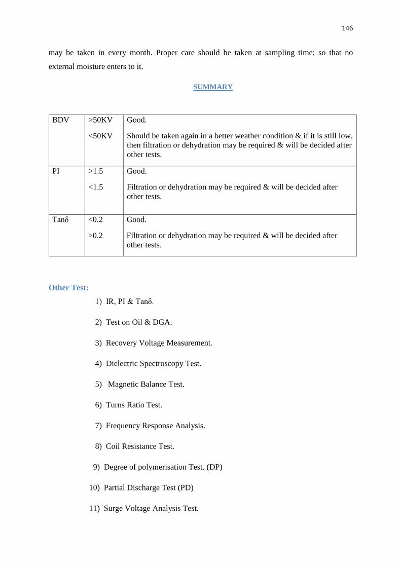
146
Contd…
may be taken in every month. Proper care should be taken at sampling time; so that no
external moisture enters to it.
SUMMARY
BDV
>50KV
<50KV
Good.
Should be taken again in a better weather condition & if it is still low, then filtration or dehydration may be required & will be decided after other tests.
PI
>1.5
<1.5
Good.
Filtration or dehydration may be required & will be decided after other tests.
Tanδ <0.2
>0.2
Good.
Filtration or dehydration may be required & will be decided after other tests.
Other Test:
1) IR, PI & Tanδ.
2) Test on Oil & DGA.
3) Recovery Voltage Measurement.
4) Dielectric Spectroscopy Test.
5) Magnetic Balance Test.
6) Turns Ratio Test.
7) Frequency Response Analysis.
8) Coil Resistance Test.
9) Degree of polymerisation Test. (DP)
10) Partial Discharge Test (PD)
11) Surge Voltage Analysis Test.