Embed Size (px)
Citation preview

CHAPTER III
CIRCUIT ANALYSIS TECHNIQUES
• Circuit Reduction & Source Transformation
• Node-Voltage method
• Mesh- Current method.
• Superposition method.
• Thevenin’s and Norton’s circuits.
• Maximum Power Transfer theorem

THE SUPERPOSITION
METHOD

OBJECTIVES
• To apply the superposition principle to solve linear circuits.
• To introduce the concept of equivalent circuits.
• To determine “Thevenin” and “Norton” Equivalent circuits.

THE SUPERPOSITION PRINCIPLE
“In any linear circuit containing multiple
independent sources, the current or voltage at any
point in the circuit may be calculated as the
algebraic sum of the individual contributions of
each source acting alone.”

HOW TO APPLY SUPERPOSITION
• To find the contribution due to an individual independent
source, zero out the other independent sources in the circuit.
• Voltage source short circuit.
• Current source open circuit.
• Solve the resulting circuit using your favorite technique(s).
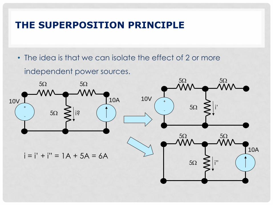
THE SUPERPOSITION PRINCIPLE
• The idea is that we can isolate the effect of 2 or more
independent power sources.
10V +
- 5W
5W 5W
i?
10A 10V +
- 5W
5W 5W
i’
5W
5W 5W
i”
10A i = i’ + i” = 1A + 5A = 6A

SUPERPOSITION PROCEDURE
For each independent source (repeat the following):
• Replace the other independent voltage sources with a short
circuit (i.e., V = 0).
• Replace the other independent current sources with an open
circuit (i.e., I = 0).
Note: Dependent sources are not changed!
• Calculate the contribution of this particular voltage or current
source to the desired output parameter.
• Algebraically sum the individual contributions (current and/or
voltage) from each independent source.

Example

Solution

Example
Use the superposition method to find Vo

THÉVENIN EQUIVALENT CIRCUIT
• Any linear 2-terminal (1-port) and active network can be
replaced by an equivalent circuit consisting of an
independent voltage source in series with a resistor.
network
of
sources
and
resistors
≡
– +
VTh
RTh
RL
iL +
vL
–
a
b
RL
iL +
vL
–
a
b
Thévenin equivalent circuit Actual circuit

NORTON EQUIVALENT CIRCUIT
• Any linear 2-terminal (1-port) network of independent voltage
sources, independent current sources, and linear resistors can
be replaced by an equivalent circuit consisting of an
independent current source in parallel with a resistor without
affecting the operation of the rest of the circuit.
Norton equivalent circuit
network
of
sources
and
resistors
≡ RL
iL +
vL
–
a
b
a
RL
iL +
vL
–
iN
b
RN

DETERMINATION OF THÉVENIN/NORTON EQUIVALENT
Calculate the open-circuit voltage, voc
Calculate the short-circuit current, isc
Note that isc is in the direction of the open-circuit voltage drop
across the terminals a,b !
sc
oc
Th
ocTh
i
vR
vV
network
of
sources
and
resistors
a
b
+
voc
–
network
of
sources
and
resistors
a
b
isc

ALTERNATIVE METHOD OF CALCULATING RTH
For a network containing only independent sources
and linear resistors:
1. Set all independent sources to zero
voltage source short circuit
current source open circuit
2. Find equivalent resistance Req between the terminals by
inspection
Or, set all independent sources to zero
1. Apply a test voltage source VTEST
2. Calculate ITEST
TEST
TEST
ThI
VR
network of
independent
sources and
resistors, with
each source
set to zero
Req
network of
independent
sources and
resistors, with
each source
set to zero
ITEST
– +
VTEST

FINDING IN
IN ≡ isc = VTh/RTh
Analogous to calculation of Thevenin Equivalent Circuit:
• Find open-circuit voltage and short-circuit current
• Or, find short-circuit current and Norton (Thevenin) resistance

FINDING IN AND RN
• We can derive the Norton equivalent circuit from a Thévenin equivalent
circuit simply by making a source transformation:
RL RN
iL
iN
+
vL
–
a
b
– +
RL
iL +
vL
–
vTh
RTh
sc
Th
Th
N
sc
oc
ThN ; i
R
vi
i
vRR
a
b

EXAMPLE
Find the Thevenin equivalent with respect to the terminals a,b:


![[PPT]Distributed Power Systems ELCT 908 - German …eee.guc.edu.eg/Courses/Electronics/ELCT908 Distributed... · Web viewDistributed Power Systems ELCT 908 Instructor: Prof. Yasser](https://img.pdfslide.net/doc/110x75/5ad00ac57f8b9ac1478d8f6c/pptdistributed-power-systems-elct-908-german-eeeguceduegcourseselectronicselct908.jpg)