Embed Size (px)
Citation preview

Chapter 3
Signal Degradation in
Optical FibersOptical Fibers
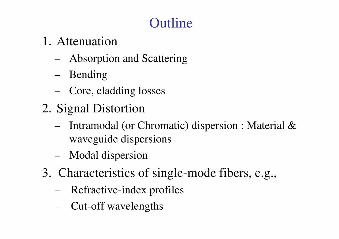
Outline
1. Attenuation
– Absorption and Scattering
– Bending
– Core, cladding losses
2. Signal Distortion
– Intramodal (or Chromatic) dispersion : Material & – Intramodal (or Chromatic) dispersion : Material &
waveguide dispersions
– Modal dispersion
3. Characteristics of single-mode fibers, e.g.,
– Refractive-index profiles
– Cut-off wavelengths

Signal Attenuation & Distortion in
Optical Fibers
• What are the loss or signal attenuation mechanism in a fiber?
• Why & to what degree do optical signals get distorted as they
propagate down a fiber?
• Signal attenuation (fiber loss) largely determines the maximum • Signal attenuation (fiber loss) largely determines the maximum
repeaterless separation between optical transmitter & receiver.
• Signal distortion cause that optical pulses to broaden as they
travel along a fiber, the overlap between neighboring pulses,
creating errors in the receiver output, resulting in the limitation
of information-carrying capacity of a fiber.
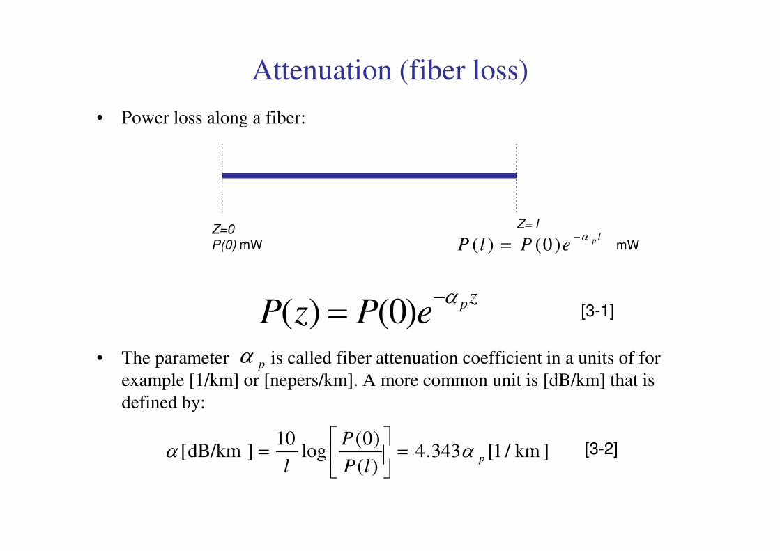
Attenuation (fiber loss)
• Power loss along a fiber:
Z=0
P(0) mW
Z= llpePlP
α−= )0()( mW
• The parameter is called fiber attenuation coefficient in a units of for
example [1/km] or [nepers/km]. A more common unit is [dB/km] that is
defined by:
zpePzPα−= )0()( [3-1]
pα
]km/1[343.4)(
)0(log
10]dB/km[ p
lP
P
lαα =
= [3-2]
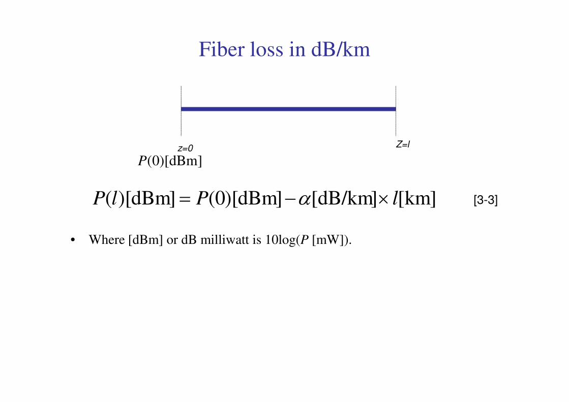
Fiber loss in dB/km
z=0 Z=l
]dBm)[0(P
]km[]dB/km[]dBm)[0(]dBm)[( lPlP ×−= α [3-3]
• Where [dBm] or dB milliwatt is 10log(P [mW]).
]km[]dB/km[]dBm)[0(]dBm)[( lPlP ×−= α [3-3]
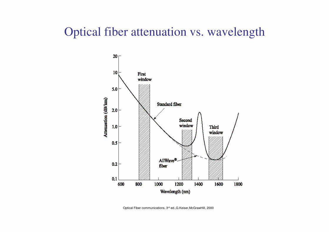
Optical fiber attenuation vs. wavelength
Optical Fiber communications, 3rd ed.,G.Keiser,McGrawHill, 2000
Absorption
• Absorption is caused by three different mechanisms:
1- Impurities in fiber material: from transition metal ions (must
be in order of parts per billion (ppb)) & particularly from OH
ions with absorption peaks at wavelengths 2700 nm, 1400 nm,
950 nm & 725nm.
2- Intrinsic absorption (fundamental lower limit): electronic
absorption band (UV region) & atomic bond vibration band
(IR region) in basic SiO2.
3- Atomic defects : typically relatively small except exposed to
nuclear radiation level (e.g., inside a nuclear reactor, nuclear
explosion)
Scattering Loss
• Scattering losses are due to microscopic variations in the
material density, compositional fluctuations (inclusion of
GeO2, P2O5, etc.), structural inhomogeneities and defects.
• The first two effects give rise to refractive-index variations.
• The refractive-index variations cause Rayleigh scattering,
which is the same phenomenon as the scattering of light in the
atmosphere giving rise to blue sky.atmosphere giving rise to blue sky.
• Rayleigh scattering is proportion to λ-4 .
• The structural inhomogeneities and defects (created during
fabrication) can cause scattering of light out of fiber. These
defects include trapped gas bubbles, unreacted starting
materials and crytallized regions.
• These defects are minimized by improving preform
manufacturing methods and this scattering is negligible
compared to the Rayleigh scattering.
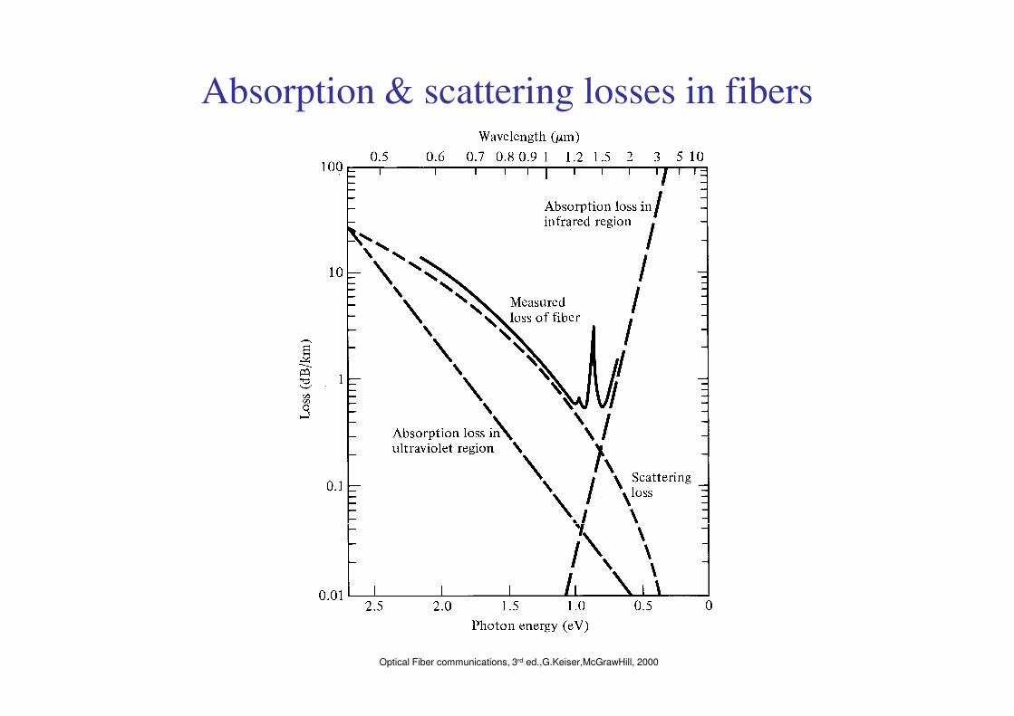
Absorption & scattering losses in fibers
Optical Fiber communications, 3rd ed.,G.Keiser,McGrawHill, 2000
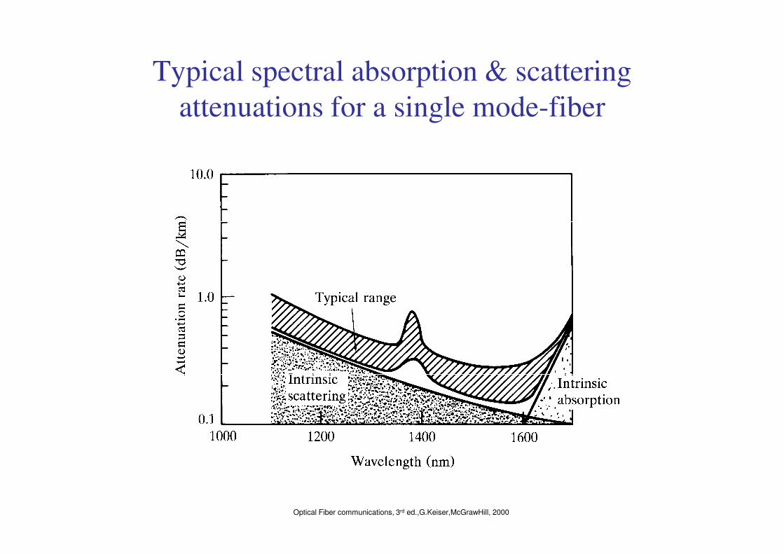
Typical spectral absorption & scattering
attenuations for a single mode-fiber
Optical Fiber communications, 3rd ed.,G.Keiser,McGrawHill, 2000

Bending Loss (Macrobending & Microbending)
Macrobending Loss: The
curvature of the bend is much
larger than fiber diameter.
Lightwave suffers sever loss due
to radiation of the evanescent
field in the cladding region. As
the radius of the curvaturethe radius of the curvature
decreases, the loss increases
exponentially until it reaches at a
certain critical radius. For any
radius a bit smaller than this
point, the losses suddenly
becomes extremely large. Higher
order modes radiate away faster
than lower order modes.
Optical Fiber communications, 3rd ed.,G.Keiser,McGrawHill, 2000
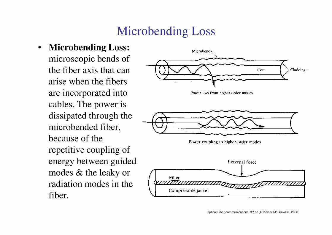
Microbending Loss
• Microbending Loss:
microscopic bends of
the fiber axis that can
arise when the fibers
are incorporated into
cables. The power is
dissipated through the dissipated through the
microbended fiber,
because of the
repetitive coupling of
energy between guided
modes & the leaky or
radiation modes in the
fiber.
Optical Fiber communications, 3rd ed.,G.Keiser,McGrawHill, 2000
Dispersion in Optical Fibers
• Dispersion: Any phenomenon in which the velocity of propagation of any electromagnetic wave is wavelength dependent.
• In communication, dispersion is used to describe any process by which any electromagnetic signal propagating in a physical medium is degraded because the various wave characteristics (i.e., frequencies) of the signal have different propagation velocities within the physical medium.within the physical medium.
• There are 3 dispersion types in the optical fibers, in general:
1- Material Dispersion
2- Waveguide Dispersion
3- Modal Dispersion -> Intermodal delay
Material & waveguide dispersions are main causes ofIntramodal Dispersion.
Group Velocity
Wave Velocities:
1- Plane wave velocity: For a plane wave propagating along z-axis in an unbounded homogeneous region of refractive index , which is represented by , the velocity of constant phase plane is:
2- Modal wave phase velocity: For a modal wave propagating along z-axis
1n)ωexp( 1zjktj −
11 n
c
kv ==
ω
2- Modal wave phase velocity: For a modal wave propagating along z-axis represented by , the velocity of constant phase plane is:
3- For transmission system operation the most important & useful type of velocity is the group velocity, . This is the actual velocity which the signal information & energy is traveling down the fiber. It is always less than the speed of light in the medium. The observable delay experiences by the optical signal waveform & energy, when traveling a length of l along the fiber is commonly referred to as group delay.
)ωexp( zjtj β−
βω
=pv
gV
Group Velocity & Group Delay• The group velocity is given by:
• The group delay is given by:
βd
dV g
ω=
dl
l βτ ==
• It is important to note that all above quantities depend both on frequency
& the propagation mode. In order to see the effect of these parameters on
group velocity and delay, the following analysis would be helpful.
ωd
dl
V
l
g
g
βτ ==
Input/Output signals in Fiber Transmission
System
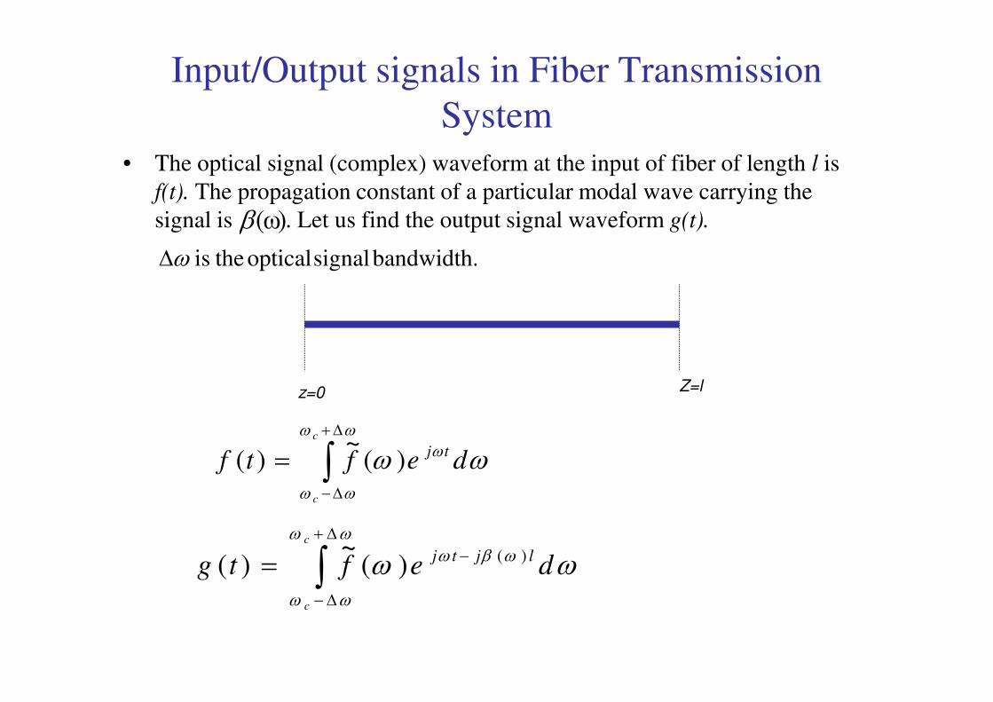
• The optical signal (complex) waveform at the input of fiber of length l is
f(t). The propagation constant of a particular modal wave carrying the
signal is . Let us find the output signal waveform g(t).)ω(βbandwidth. signal optical theis ω∆
z=0 Z=l
∫∆+
∆−
=ωω
ωω
ω ωωc
c
deftftj)(
~)(
∫∆+
∆−
−=ωω
ωω
ωβω ωωc
c
deftgljtj )()(
~)(
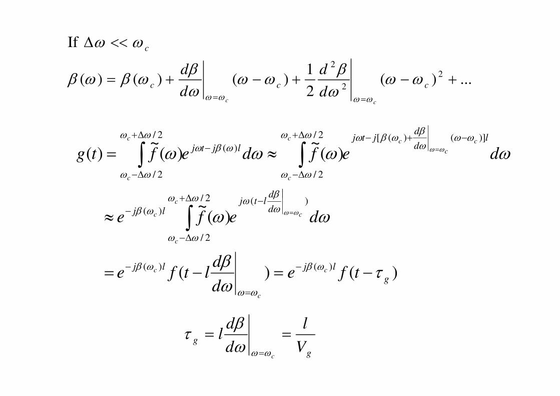
...)(2
1)()()(
If
2
2
2
+−+−+=
<<∆
==ccc
c
ccd
d
d
dωω
ωβ
ωωωβ
ωβωβ
ωω
ωωωω
~
)(~
)(~
)(
)(2/
)]()([2/
2/
)(
2/
2/
dltj
ld
djtj
ljtjdefdeftg
c
c
c
cc
c
c
c
ωωωω
βωωω
ωωωβ
ωβωωω
ωω
ωβωωω
ωω
ωω≈=
−∆+
−+−∆+
∆−
−∆+
∆−
=∫∫
)()(
)(~
)()(
)(2/
2/
)(
g
ljlj
d
dltj
lj
tfed
dltfe
defe
c
c
c
c
c
c
c
τωβ
ωω
ωβ
ωω
ωβ
ωβ
ωωω
ωω
ωβ ωω
−=−=
≈
−
=
−
−∆+
∆−
− =∫
g
gV
l
d
dl
c
===ωωω
βτ
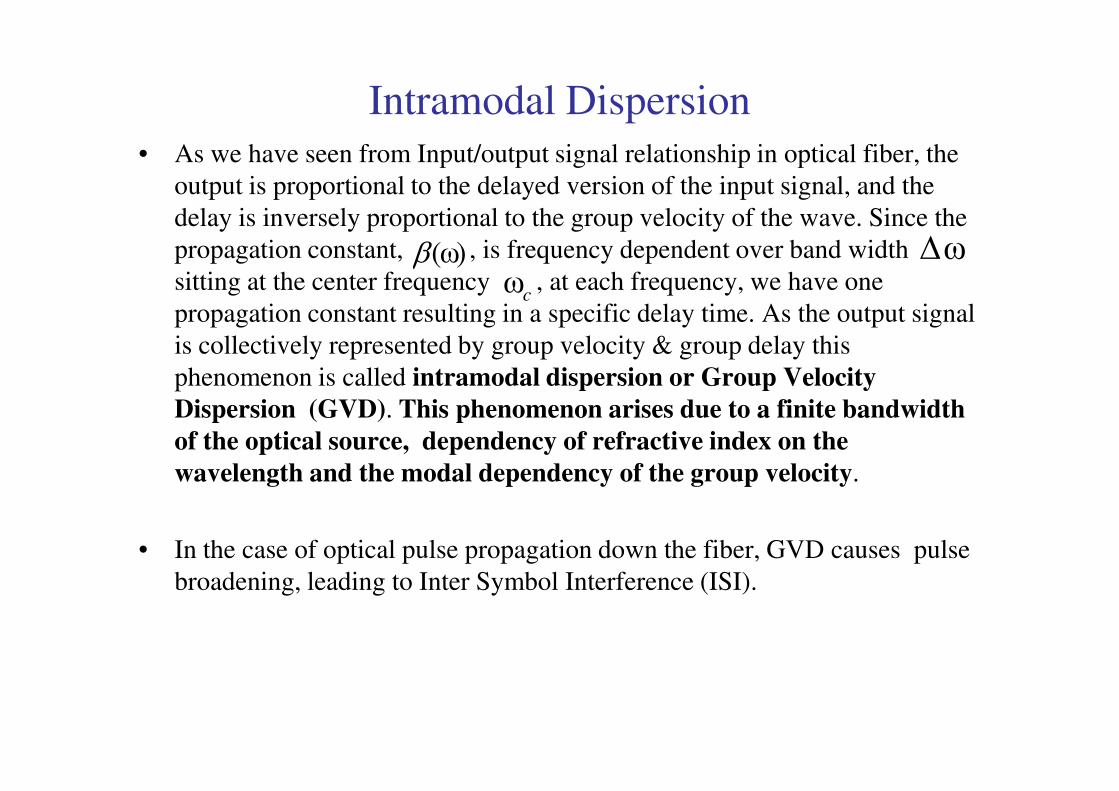
Intramodal Dispersion• As we have seen from Input/output signal relationship in optical fiber, the
output is proportional to the delayed version of the input signal, and the
delay is inversely proportional to the group velocity of the wave. Since the
propagation constant, , is frequency dependent over band width
sitting at the center frequency , at each frequency, we have one
propagation constant resulting in a specific delay time. As the output signal
is collectively represented by group velocity & group delay this
phenomenon is called intramodal dispersion or Group Velocity
Dispersion (GVD). This phenomenon arises due to a finite bandwidth
)ω(β ω∆cω
Dispersion (GVD). This phenomenon arises due to a finite bandwidth
of the optical source, dependency of refractive index on the
wavelength and the modal dependency of the group velocity.
• In the case of optical pulse propagation down the fiber, GVD causes pulse
broadening, leading to Inter Symbol Interference (ISI).
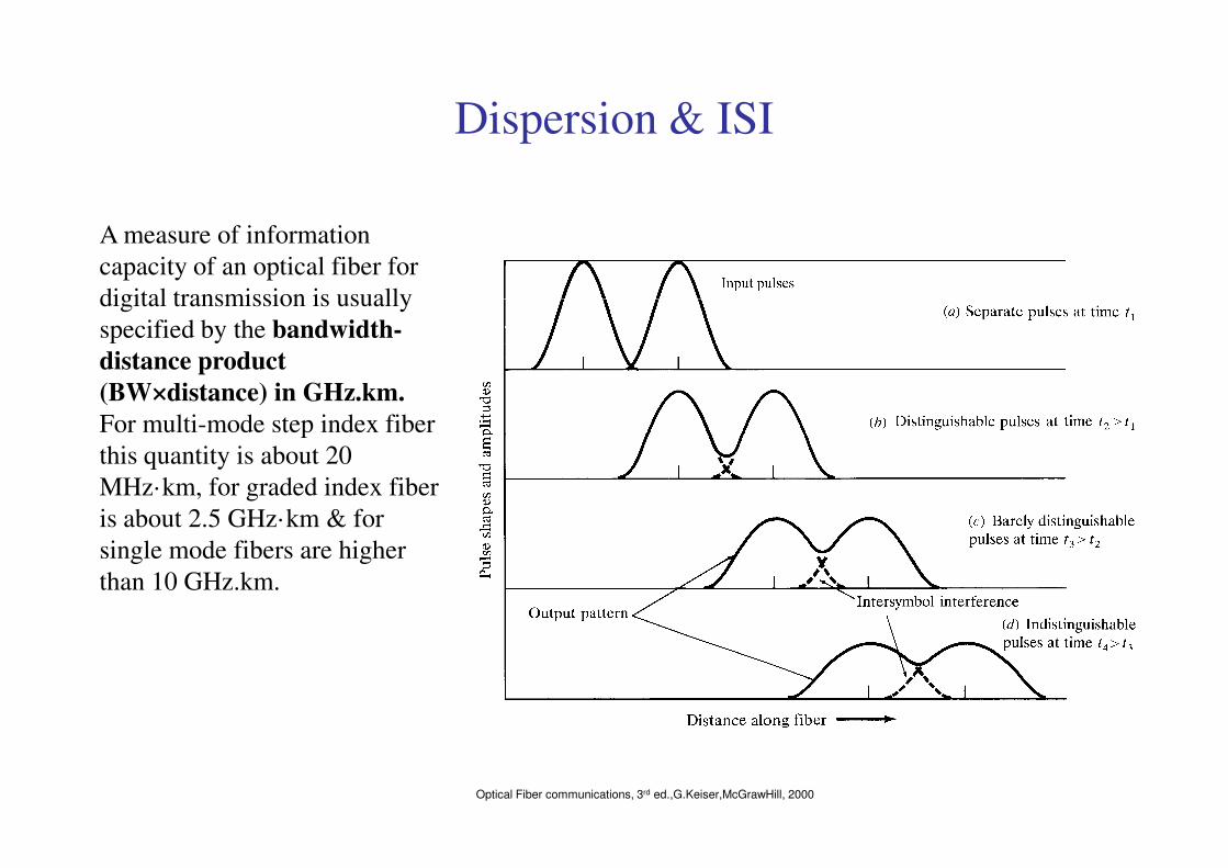
Dispersion & ISI
A measure of information
capacity of an optical fiber for
digital transmission is usually
specified by the bandwidth-
distance product
(BW×distance) in GHz.km.
For multi-mode step index fiber
Optical Fiber communications, 3rd ed.,G.Keiser,McGrawHill, 2000
For multi-mode step index fiber
this quantity is about 20
MHz·km, for graded index fiber
is about 2.5 GHz·km & for
single mode fibers are higher
than 10 GHz.km.
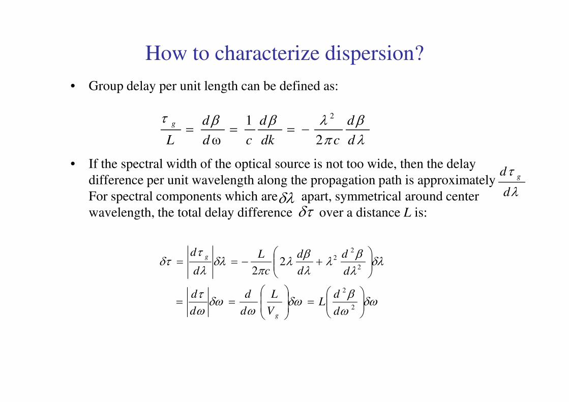
How to characterize dispersion?
• Group delay per unit length can be defined as:
• If the spectral width of the optical source is not too wide, then the delay
difference per unit wavelength along the propagation path is approximately
For spectral components which are apart, symmetrical around center
λβ
πλββτ
d
d
cdk
d
cd
d
L
g
2
1
ω
2
−===
λ
τ
d
d g
δλFor spectral components which are apart, symmetrical around center
wavelength, the total delay difference over a distance L is: δλ
δτ
δωωβ
δωω
δωωτ
δλλβ
λλβ
λπ
δλλ
τδτ
=
==
+−==
2
2
2
22
22
d
dL
V
L
d
d
d
d
d
d
d
d
c
L
d
d
g
g
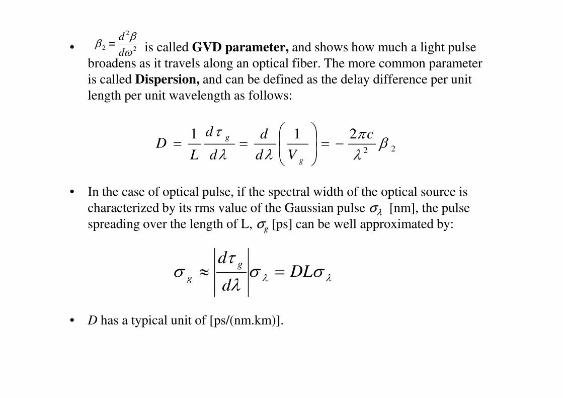
• is called GVD parameter, and shows how much a light pulse
broadens as it travels along an optical fiber. The more common parameter
is called Dispersion, and can be defined as the delay difference per unit
length per unit wavelength as follows:
• In the case of optical pulse, if the spectral width of the optical source is
σ
2
2
2 ωβ
βd
d≡
22
211β
λπ
λλ
τ c
Vd
d
d
d
LD
g
g −=
==
characterized by its rms value of the Gaussian pulse σλ [nm], the pulse
spreading over the length of L, σg [ps] can be well approximated by:
• D has a typical unit of [ps/(nm.km)].
λλ σσλ
τσ DL
d
d g
g =≈
Spread, ² τSpectrum, ² λ
Intensity Intensity Intensity
Cladding
CoreEmitter
Very short
light pulse
vg(λ
2)
vg(λ
1)
Input
Output
Material Dispersion
τtt
0λ
λ1λ2λo
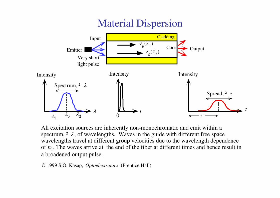
All excitation sources are inherently non-monochromatic and emit within aspectrum, ² λ, of wavelengths. Waves in the guide with different free spacewavelengths travel at different group velocities due to the wavelength dependenceof n1. The waves arrive at the end of the fiber at different times and hence result in
a broadened output pulse.
© 1999 S.O. Kasap, Optoelectronics (Prentice Hall)
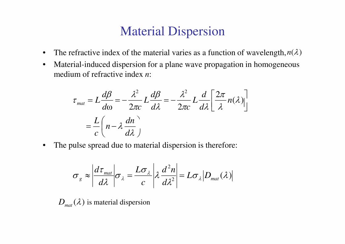
Material Dispersion
• The refractive index of the material varies as a function of wavelength,
• Material-induced dispersion for a plane wave propagation in homogeneous
medium of refractive index n:
)(λn
−=
−=−==
λ
λλπ
λπλ
λβ
πλβ
τ
dnn
L
nd
dL
cd
dL
cd
dLmat
)(2
22ω
22
• The pulse spread due to material dispersion is therefore:
−=λ
λd
dnn
c
L
)(2
2
λσλ
λσ
σλτ
σ λλ
λ matmat
g DLd
nd
c
L
d
d==≈
)(λmatD is material dispersion
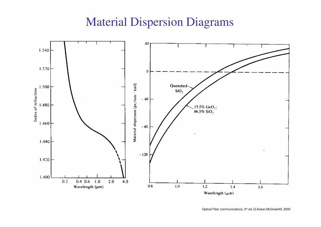
Material Dispersion Diagrams
Optical Fiber communications, 3rd ed.,G.Keiser,McGrawHill, 2000

Waveguide Dispersion
• Waveguide dispersion is due to the dependency of the group velocity of the
fundamental mode as well as other modes on the V number, (see Fig 2-18
of the textbook). In order to calculate waveguide dispersion, we consider
that n is not dependent on wavelength. Defining the normalized
propagation constant b as:
2
22
2
2
22 //
nn
nk
nn
nkb
−−
≈−
−=
ββ
• solving for propagation constant:
• Using V number:
21
2
2
2
1nnnn
b−
≈−
=
1212 /)();1( nnnbkn −=∆∆+≈β
∆≈−= 2)( 1
2/12
2
2
1 kannnkaV
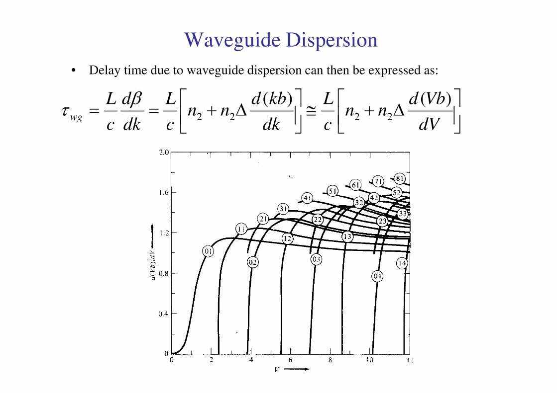
Waveguide Dispersion
• Delay time due to waveguide dispersion can then be expressed as:
∆+≅
∆+==dV
Vbdnn
c
L
dk
kbdnn
c
L
dk
d
c
Lwg
)()(2222
βτ
Optical Fiber communications, 3rd ed.,G.Keiser,McGrawHill, 2000

Waveguide dispersion in single mode fibers
• For single mode fibers, waveguide dispersion is in the same order of
material dispersion. The pulse spread can be well approximated as:
2
2
2 )()(
dV
VbdV
c
LnDL
d
dwg
wg
wg λσ
λσσλ
τσ λ
λλ
∆−==≈
)(λwgD
Optical Fiber communications, 3rd ed.,G.Keiser,McGrawHill, 2000
)(λwgD
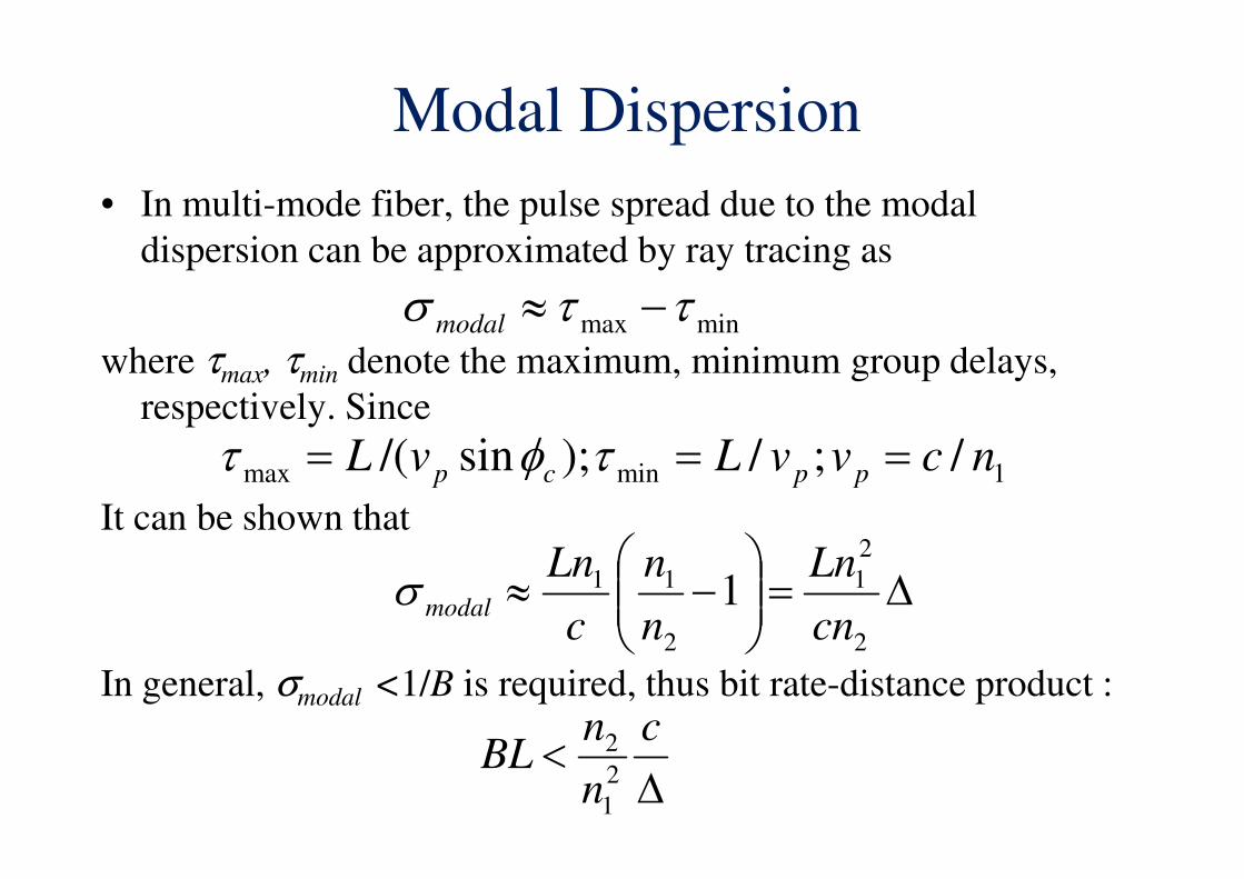
Modal Dispersion
• In multi-mode fiber, the pulse spread due to the modal
dispersion can be approximated by ray tracing as
where τmax, τmin denote the maximum, minimum group delays,
respectively. Since
minmax ττσ −≈modal
/;/);sin/( ncvvLvL === τφτIt can be shown that
In general, σmodal <1/B is required, thus bit rate-distance product :
∆=
−≈
2
2
1
2
11 1cn
Ln
n
n
c
Lnmodalσ
1minmax /;/);sin/( ncvvLvL ppcp === τφτ
∆<
c
n
nBL
2
1
2
Polarization Mode dispersion
Core
z
n1 x
// x
n1y
// y
Ey
Ex
Ex
Ey
∆τ = Pulse spread
Output light pulse
t
t
∆τ
Intensity
EInput light pulse
t
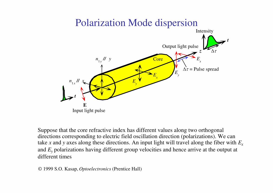
Suppose that the core refractive index has different values along two orthogonaldirections corresponding to electric field oscillation direction (polarizations). We cantake x and y axes along these directions. An input light will travel along the fiber with Ex
and Ey polarizations having different group velocities and hence arrive at the output at
different times
© 1999 S.O. Kasap, Optoelectronics (Prentice Hall)
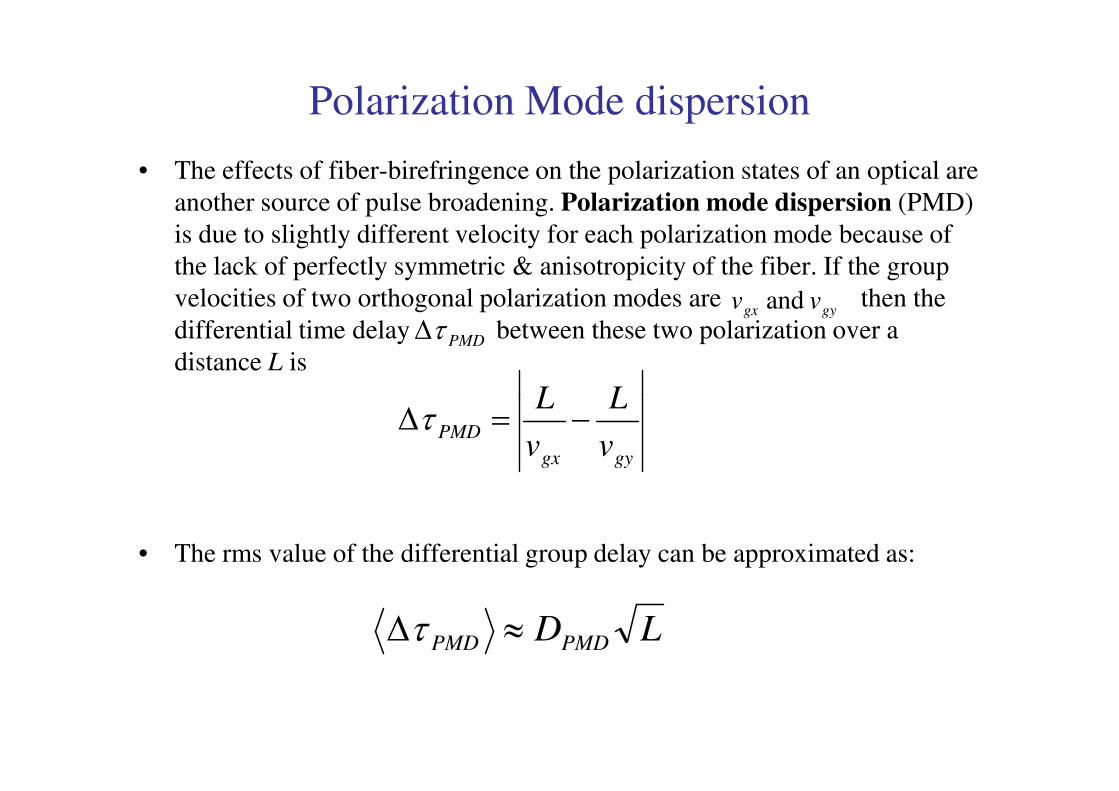
Polarization Mode dispersion
• The effects of fiber-birefringence on the polarization states of an optical are
another source of pulse broadening. Polarization mode dispersion (PMD)
is due to slightly different velocity for each polarization mode because of
the lack of perfectly symmetric & anisotropicity of the fiber. If the group
velocities of two orthogonal polarization modes are then the
differential time delay between these two polarization over a
distance L is
gygx vv and
PMDτ∆
LL
• The rms value of the differential group delay can be approximated as:
gygx
PMDv
L
v
L−=∆τ
LDPMDPMD ≈∆τ
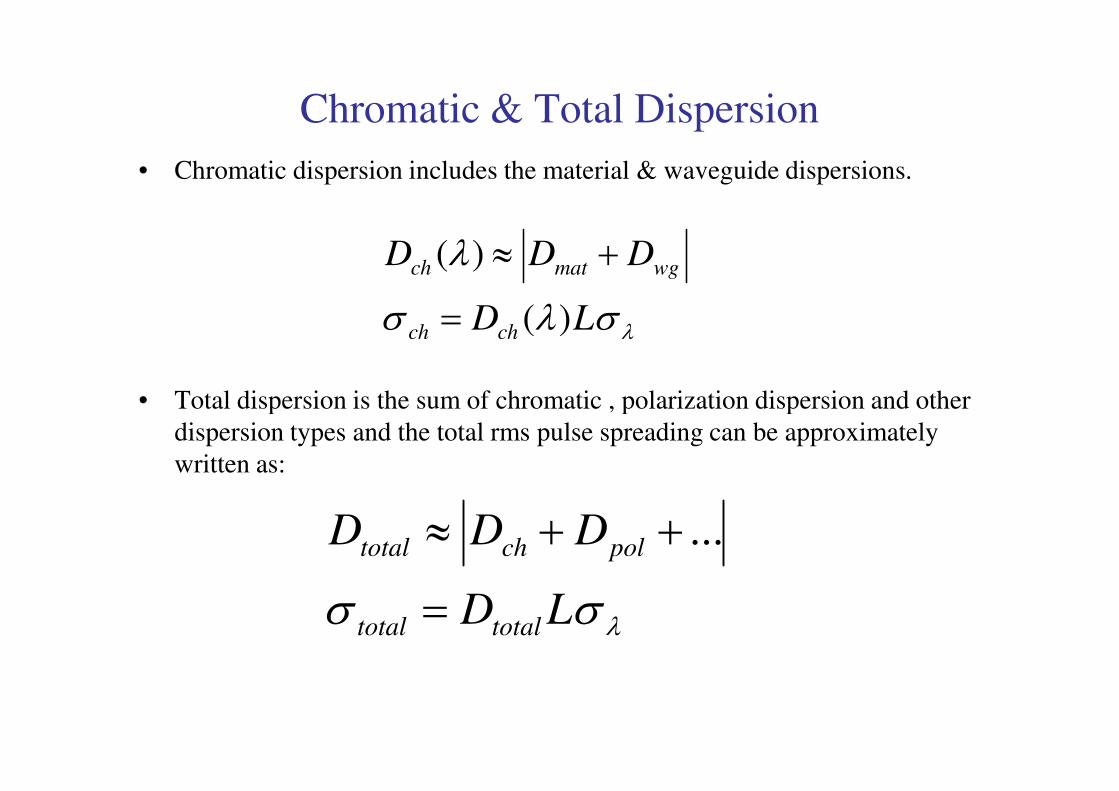
Chromatic & Total Dispersion
• Chromatic dispersion includes the material & waveguide dispersions.
• Total dispersion is the sum of chromatic , polarization dispersion and other
λσλσ
λ
LD
DDD
chch
wgmatch
)(
)(
=
+≈
• Total dispersion is the sum of chromatic , polarization dispersion and other
dispersion types and the total rms pulse spreading can be approximately
written as:
λσσ LD
DDD
totaltotal
polchtotal
=
++≈ ...
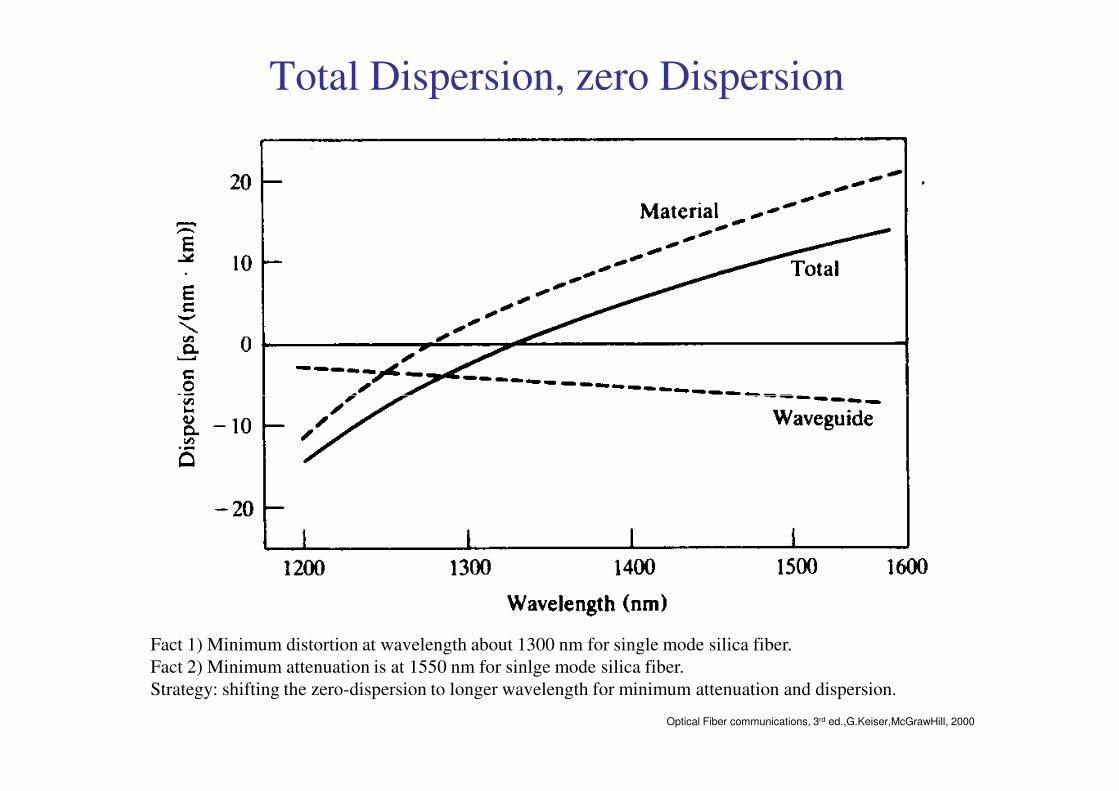
Total Dispersion, zero Dispersion
Optical Fiber communications, 3rd ed.,G.Keiser,McGrawHill, 2000
Fact 1) Minimum distortion at wavelength about 1300 nm for single mode silica fiber.
Fact 2) Minimum attenuation is at 1550 nm for sinlge mode silica fiber.
Strategy: shifting the zero-dispersion to longer wavelength for minimum attenuation and dispersion.
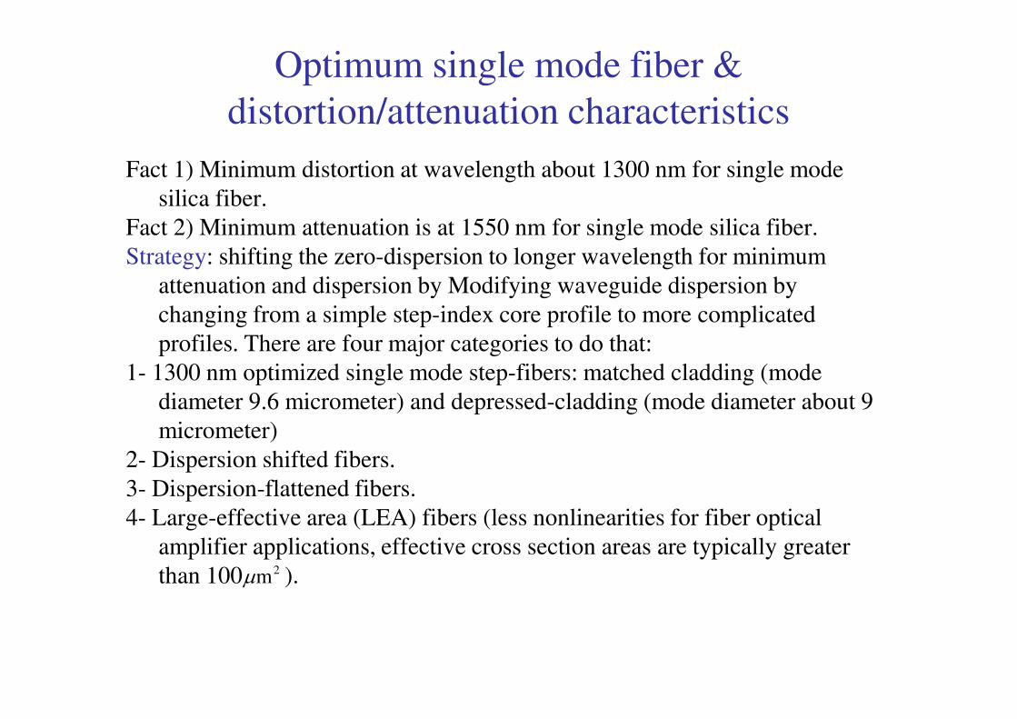
Optimum single mode fiber &
distortion/attenuation characteristics
Fact 1) Minimum distortion at wavelength about 1300 nm for single mode
silica fiber.
Fact 2) Minimum attenuation is at 1550 nm for single mode silica fiber.
Strategy: shifting the zero-dispersion to longer wavelength for minimum
attenuation and dispersion by Modifying waveguide dispersion by
changing from a simple step-index core profile to more complicated
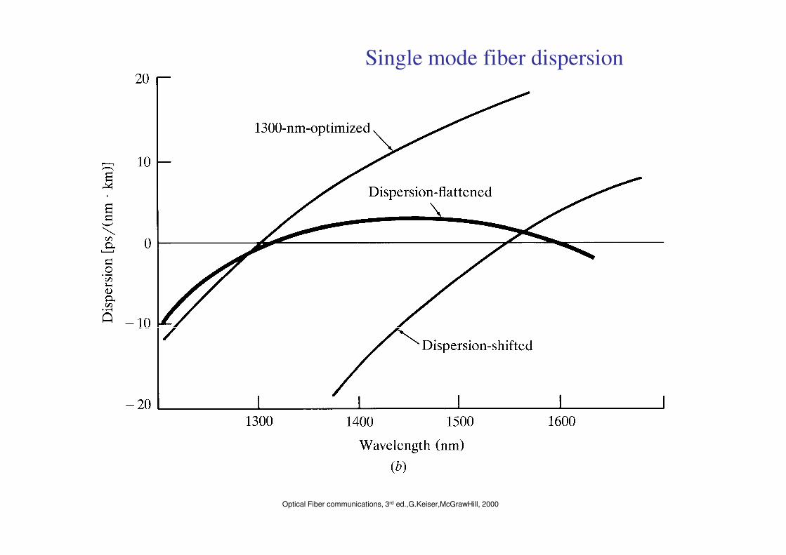
profiles. There are four major categories to do that:
1- 1300 nm optimized single mode step-fibers: matched cladding (mode 1- 1300 nm optimized single mode step-fibers: matched cladding (mode
diameter 9.6 micrometer) and depressed-cladding (mode diameter about 9
micrometer)
2- Dispersion shifted fibers.
3- Dispersion-flattened fibers.
4- Large-effective area (LEA) fibers (less nonlinearities for fiber optical
amplifier applications, effective cross section areas are typically greater
than 100 ).2mµ
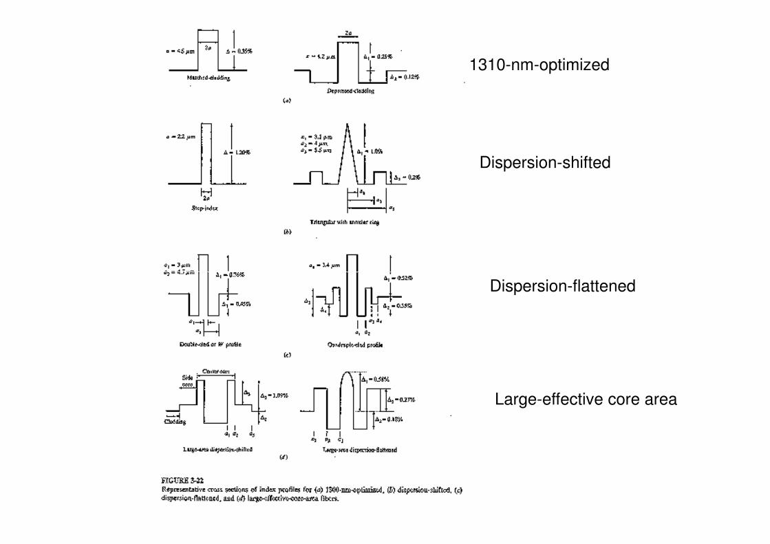
1310-nm-optimized
Dispersion-shifted
Dispersion-flattened
Large-effective core area
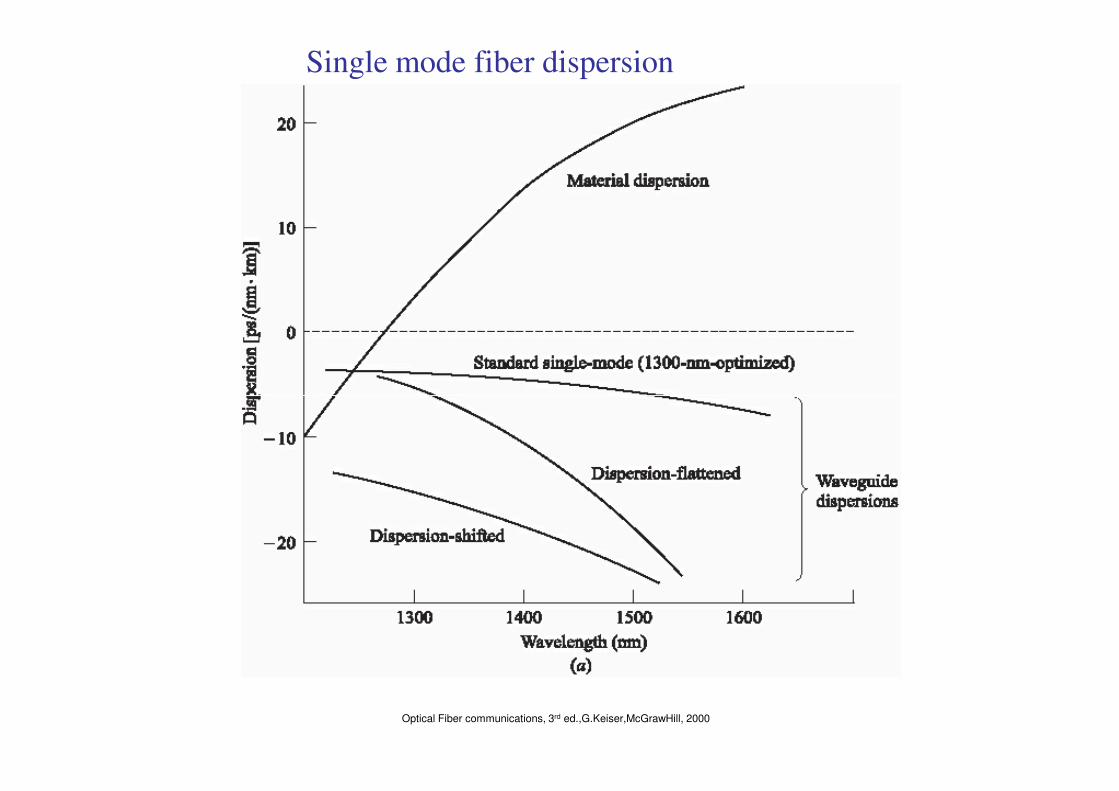
Single mode fiber dispersion
Optical Fiber communications, 3rd ed.,G.Keiser,McGrawHill, 2000
Single mode fiber dispersion
Optical Fiber communications, 3rd ed.,G.Keiser,McGrawHill, 2000
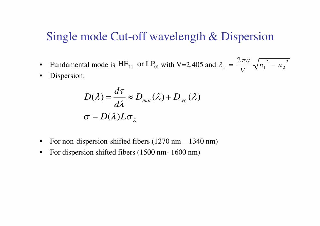
Single mode Cut-off wavelength & Dispersion
• Fundamental mode is with V=2.405 and
• Dispersion:
0111 LPor HE 2
2
2
1
2nn
V
ac −=
πλ
σλσ
λλλτ
λ
LD
DDd
dD wgmat
)(
)()()(
=
+≈=
• For non-dispersion-shifted fibers (1270 nm – 1340 nm)
• For dispersion shifted fibers (1500 nm- 1600 nm)
λσλσ LD )(=
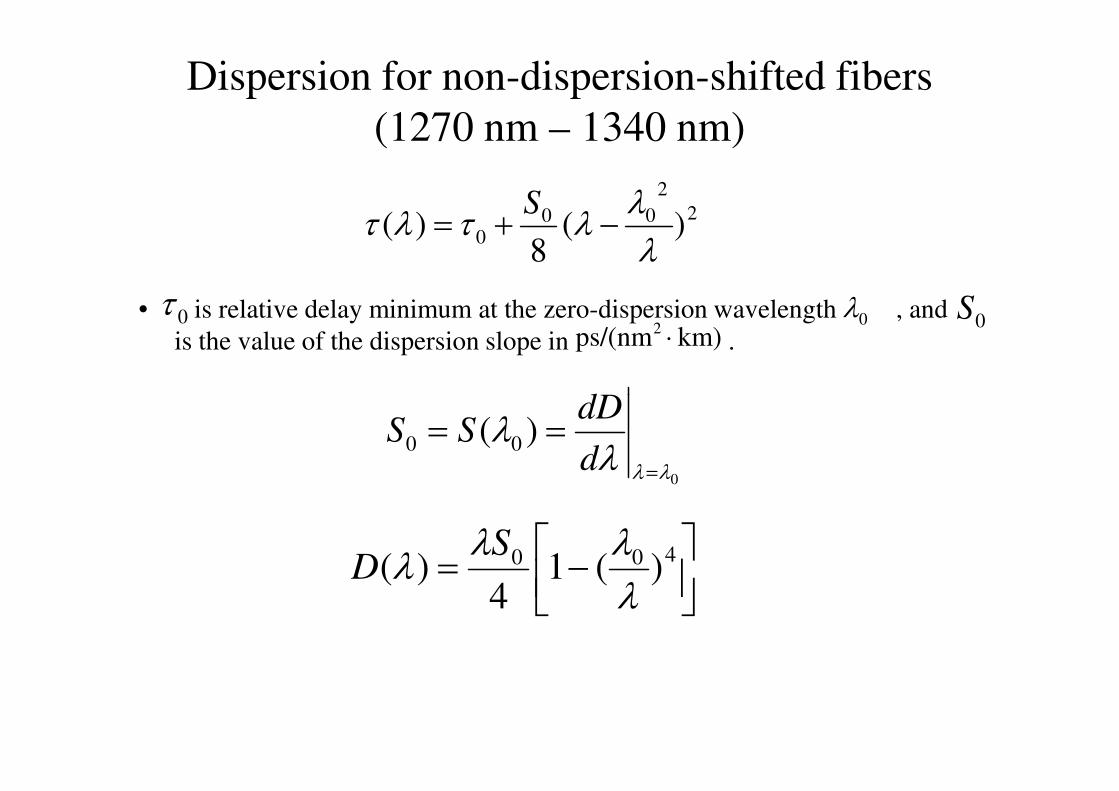
Dispersion for non-dispersion-shifted fibers
(1270 nm – 1340 nm)
• is relative delay minimum at the zero-dispersion wavelength , and
is the value of the dispersion slope in .
2
2
000 )(
8)(
λλ
λτλτ −+=S
0τ 0λ 0Skm)ps/(nm2 ⋅
dD
0
)( 00
λλλλ
=
==d
dDSS
−= 400 )(14
)(λλλ
λS
D
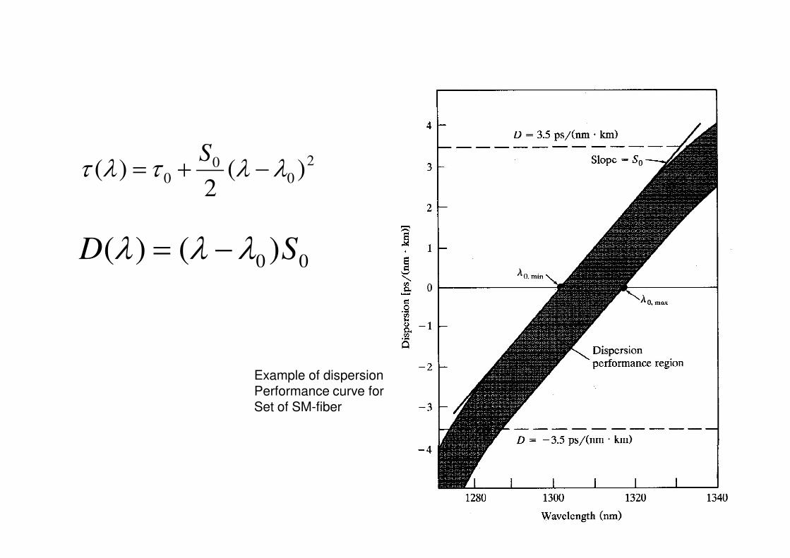
2
00
0 )(2
)( λλτλτ −+=S
00 )()( SD λλλ −=
Example of dispersionPerformance curve for Set of SM-fiber
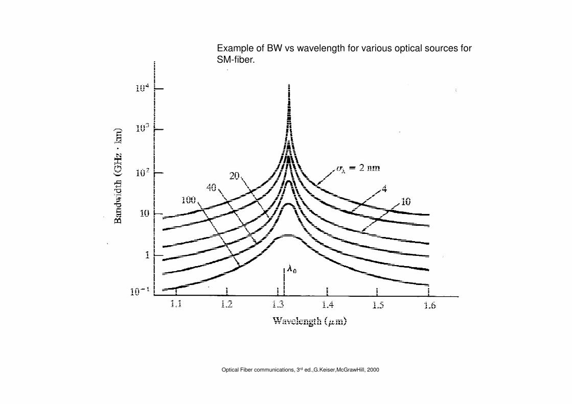
Example of BW vs wavelength for various optical sources for SM-fiber.
Optical Fiber communications, 3rd ed.,G.Keiser,McGrawHill, 2000
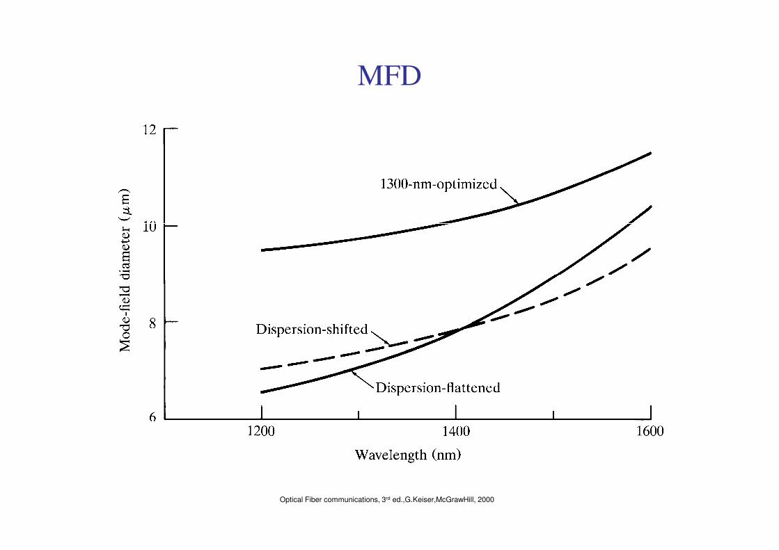
MFD
Optical Fiber communications, 3rd ed.,G.Keiser,McGrawHill, 2000
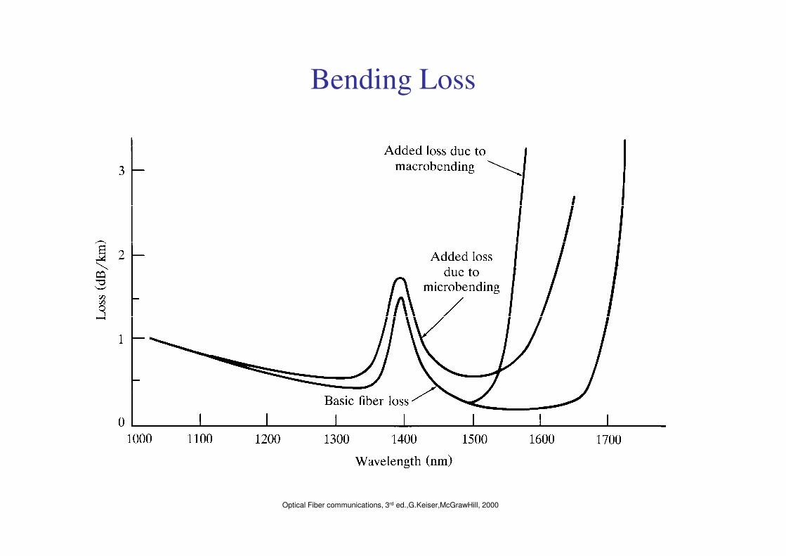
Bending Loss
Optical Fiber communications, 3rd ed.,G.Keiser,McGrawHill, 2000
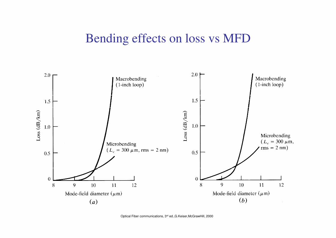
Bending effects on loss vs MFD
Optical Fiber communications, 3rd ed.,G.Keiser,McGrawHill, 2000
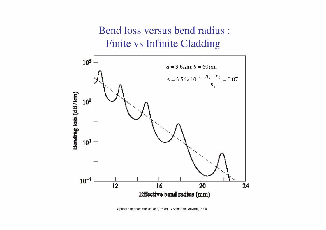
Bend loss versus bend radius :
Finite vs Infinite Cladding
07.0 ;1056.3
m60 ;m6.3
2
233 =−
×=∆
==
−
n
nn
ba µµ
Optical Fiber communications, 3rd ed.,G.Keiser,McGrawHill, 2000