Embed Size (px)
Citation preview
Nebraska Department of Transportation - Roadway Design Manual July 2006 Chapter Seven: Earthwork Page 7-1 The information contained in Chapter Seven: Earthwork, dated July 2006, has been updated to reflect the February 2018 Errata. The errata addresses errors, changes in procedure, changes in NDOT department titles, changes in other Roadway Design Manual chapters and other reference material citations which have occurred since the latest publication of this chapter.
Chapter Seven Earthwork
The following items are not earthwork items; do not include these items in your grading quantities:
• Shoulder Construction (Surfacing pay item, See Chapter Eight: Surfacing, Section 4.C). • Median Construction (Surfacing pay item, See EXHIBIT 4.23 and the Standard Specifications
for Highway Construction, (Reference 7.2), Section 308), (http://dot.nebraska.gov/media/10343/2017-specbook.pdf).
• Excavation for Box Culverts (Culverts pay item, See the Drainage Design and Erosion Control Manual, (Reference 7.1), Chapter One: Drainage, Section 8.R), (http://www.roads.nebraska.gov/business-center/design-consultant/rd-manuals/).
• Excavation for Culvert Pipes and Headwalls (Culverts pay item, See the Drainage Design and Erosion Control Manual, (Reference 7.1), Chapter One: Drainage, Section 8.R).
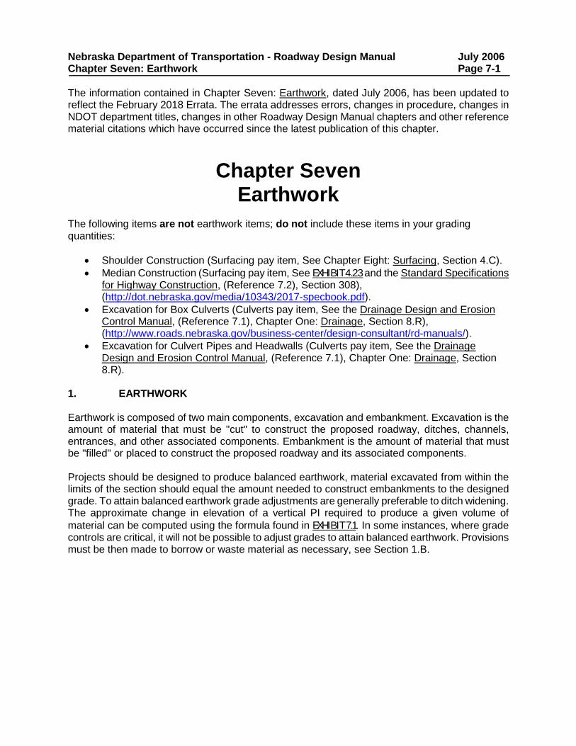
1. EARTHWORK Earthwork is composed of two main components, excavation and embankment. Excavation is the amount of material that must be "cut" to construct the proposed roadway, ditches, channels, entrances, and other associated components. Embankment is the amount of material that must be "filled" or placed to construct the proposed roadway and its associated components. Projects should be designed to produce balanced earthwork, material excavated from within the limits of the section should equal the amount needed to construct embankments to the designed grade. To attain balanced earthwork grade adjustments are generally preferable to ditch widening. The approximate change in elevation of a vertical PI required to produce a given volume of material can be computed using the formula found in EXHIBIT 7.1. In some instances, where grade controls are critical, it will not be possible to adjust grades to attain balanced earthwork. Provisions must be then made to borrow or waste material as necessary, see Section 1.B.
Nebraska Department of Transportation - Roadway Design Manual July 2006 Chapter Seven: Earthwork Page 7-2
Exhibit 7.1 Earthwork Computation Formula Adjustment to the roadway side slopes and adjustments to the grading within loops and ramps, to either slightly reduce fill requirements or gain excavation, should be weighed against safety criteria, possible aesthetic damage and maintenance problems in these areas. The following summarizes the earthwork considerations associated with mainline alignment design:
1. Urban/Rural. Earthwork balance is generally practical only in rural areas. In urban areas other considerations such as limiting right-of-way impacts and matching elevations of existing development may have a higher priority than balancing earthwork.
2. Borrow Sites. The availability and quality of borrow sites in the vicinity of the project will impact the feasibility of balancing earthwork. Environmental, archaeological and historical considerations can prevent the use of otherwise acceptable sites. Generally, the use of borrow should be minimized. When borrow cannot be avoided, borrow sites should be discussed at the plan-in-hand. Costs should be held to a minimum by obtaining borrow from wetland mitigation sites, existing borrow pits, snow control areas, etc.
3. Balance Points. Wherever practical, earthwork should be balanced at bridges, railroad crossings, roadway intersections, and at other manmade or natural interruptions in the roadway. Short balances of 100 to 300 ft. (30 to 100 m) should generally not be shown on the plans but should be shown as part of a combined larger balance. The desirable length of balances should be from 0.5 mile to 1 mile (0.80 km to 1.6 km), with one mile (1.6 km) being the preferred balance length.
L, ft. (meter)
Average width of limits of construction = W, ft. (meter)
Old P.I.
New P.I.
XChange in P.I.
Elevation, ft. (meter)
If the volume of additional excavation required is V, cu. yd. (cubic meter) then:
English: X = V/(1.85WL) Metric: X = V/(0.5WL)
Nebraska Department of Transportation - Roadway Design Manual July 2006 Chapter Seven: Earthwork Page 7-3 1.A Computations Currently there are a variety of computer programs available for earthwork computations. Although the methods may vary, the basic approach is the same:
• Identify existing ground cross-sections with elevations. • Specify proposed roadway templates with centerline subgrade elevations. • Compute cross-section end areas of cut and fill. • Compute volumes of excavation and embankment. • Establish balance points and perform an earthwork distribution analysis.
Regardless of the program used, earthwork computations are used to determine pay quantities and to verify final calculations in the field. NDOT designers should refer to the Business Technology Support Division – IT Support for assistance with the earthwork calculations computer programs. 1.A.1 Data Requirements The following information is needed to perform earthwork calculations, regardless of the method used:
• Proposed horizontal and vertical alignments. • Cross-sections of the existing terrain every 100 feet (25 meters) or where the terrain
changes. • Proposed design-cross-sections.
1.A.2 Balance Factors Balance factors are multipliers applied to the embankment (fill) volumes to adjust for the shrinkage or swell of the soils used for the embankment. When soil is excavated, hauled and compacted into an embankment, the final volume of the compacted soil is usually less than when it is in its natural state. This difference in volume is usually defined as shrinkage. When rock is excavated, broken and placed into an embankment, it will occupy more space than rock in solid form due to the increase in void spaces. This increase in volume is known as swell. The amount of shrinkage and swell are quantified as balance factors and are percentages of the original volume. In most cases, one balance factor is used for an entire project; therefore, an average balance factor must be determined for the various materials encountered over the length of a project. At the plan-in-hand field inspection possible balance factors can be discussed based on previous similar projects and individual design experience. The Materials and Research Division may also be consulted for recommendations on specific adjustments.
Nebraska Department of Transportation - Roadway Design Manual July 2006 Chapter Seven: Earthwork Page 7-4 1.A.3 Distribution Analysis Distribution analysis helps the designer to determine if the earthwork is going to be balanced, borrowed or wasted. A balance in earthwork is obtained when the amount of available excavation equals the amount of embankment needed in-place (after compaction). The amount of adjusted embankment needed is the measured volume of embankment times the balance factor. Sometimes the adjusted embankment required exceeds the amount of excavation available. In those instances, borrow, from either contractor or state-furnished borrow pits, is required. Waste occurs when the amount of available excavation exceeds the amount of needed embankment. The leftover material must be disposed of at approved waste sites or it may be used for shoulder construction (shoulder construction is not a part of the earthwork, it is a surfacing item and is paid for by the station, see Chapter Eight: Surfacing, Section 4.C). It will be determined at the plan-in-hand field inspection if a project is to be balanced with material from the right-of-way, using contractor-furnished borrow, using state-furnished borrow, or if it will be necessary to waste excess material. Considerations in determining if earthwork balance is practical for a given project include:
• Right-of-way limitations. • Matching existing elevations of cross roads, bridges or existing roads. • The availability and quality of borrow sites within the vicinity of the project. • Will the borrow be State-furnished or contractor-furnished. • Would earthwork balance require crossing bridges or going through towns with earth
hauling equipment. • The availability of waste sites within the vicinity of the project. • Environmental, archaeological and historical considerations.
Information regarding the distribution of earthwork is required. Whether distribution analysis is generated manually or electronically, the following information must be shown in the distribution analysis for each station:
• End areas in sq. ft. (m2) of excavation and embankment. • Accumulated volume of excavation. • Accumulated volume of embankment. • Added quantities for intersections, large driveways, etc. • Balance factor(s). • Mass ordinate.
The above information, together with the identification of approximate balance points, is considered adequate. Mass diagrams generally are not plotted. The computer program provides a summary of earthwork distribution analysis.
Nebraska Department of Transportation - Roadway Design Manual July 2006 Chapter Seven: Earthwork Page 7-5 The following guidelines should be used when doing the earthwork distribution analysis:
• Desirable balance lengths should be from one half mile (0.80 km) to one mile (1.6 km) with one mile being the preferred length.
• Short balances of 300 ft. (100 m) or less should not generally be shown on the plans, they should be shown as part of a combined larger balance.
• For rural projects constructed under traffic, earthwork distribution analysis for the left and right side of the roadway should be computed separately, for information only. This shows earthwork for each side so that the contractor knows how much material must be hauled across traffic.
• Earthwork should balance at major highway intersections, both sides of towns, rivers or major streams or other natural breaks. Do not haul across bridges or through towns if possible.
• An earthwork analysis should be developed and quantities shown on plans for each phase of construction, for information only.
• Haul distances should be kept to a minimum. • The volume of existing pavement to be wasted or salvaged shall be eliminated from the
earthwork run. • Earthwork in urban areas should be either "Excavation Established Quantity" or
"Earthwork Measured in Embankment." Urban projects usually will not be balanced. • Earthwork quantities for temporary roads may be determined using established quantities.
Temporary road material is put in as embankment and removed as excavation specified for the temporary road. Earthwork quantities for temporary roads may also be incorporated in the roadway earthwork if the designer includes the temporary road structure in the computer calculations.
1.A.3.a Haul Considerations Haul is the distance excavated material is moved, as shown on the plans, from the location where the material is obtained to the location where the material is to be deposited. When distribution analysis is performed, the following questions should be considered in order to keep haul distances to a minimum:
• Is waste available from the other side of the road? • Is waste available from adjacent balances? • Could contractor-furnished borrow be used? • Could balance points be adjusted?
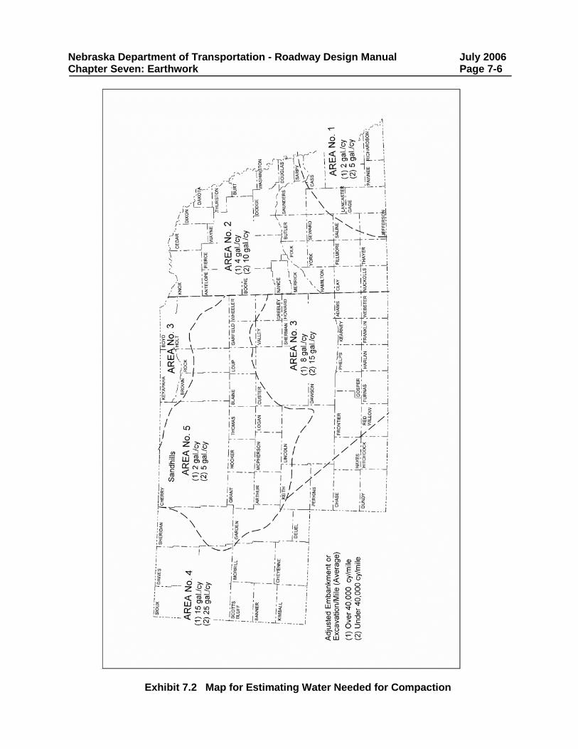
1.A.4 Moisture Content The moisture content of soil at the time of compaction shall be within the moisture range designated in the Soils and Situation Report (See Section 6.A.3). When the moisture content is not within the acceptable range, water must be added or the soil must be aerated depending upon the moisture content of the soil. EXHIBIT 7.2 should be used to estimate the amount of water that may need to be applied to obtain optimum moisture content when estimating grading costs. EXHIBIT 7.2 is based on excavation quantities; adjustments are required when paying for the quantity “Earthwork Measured in Embankment”, (See Section 1.A.5.a).
Nebraska Department of Transportation - Roadway Design Manual July 2006 Chapter Seven: Earthwork Page 7-6
Exhibit 7.2 Map for Estimating Water Needed for Compaction
Nebraska Department of Transportation - Roadway Design Manual July 2006 Chapter Seven: Earthwork Page 7-7
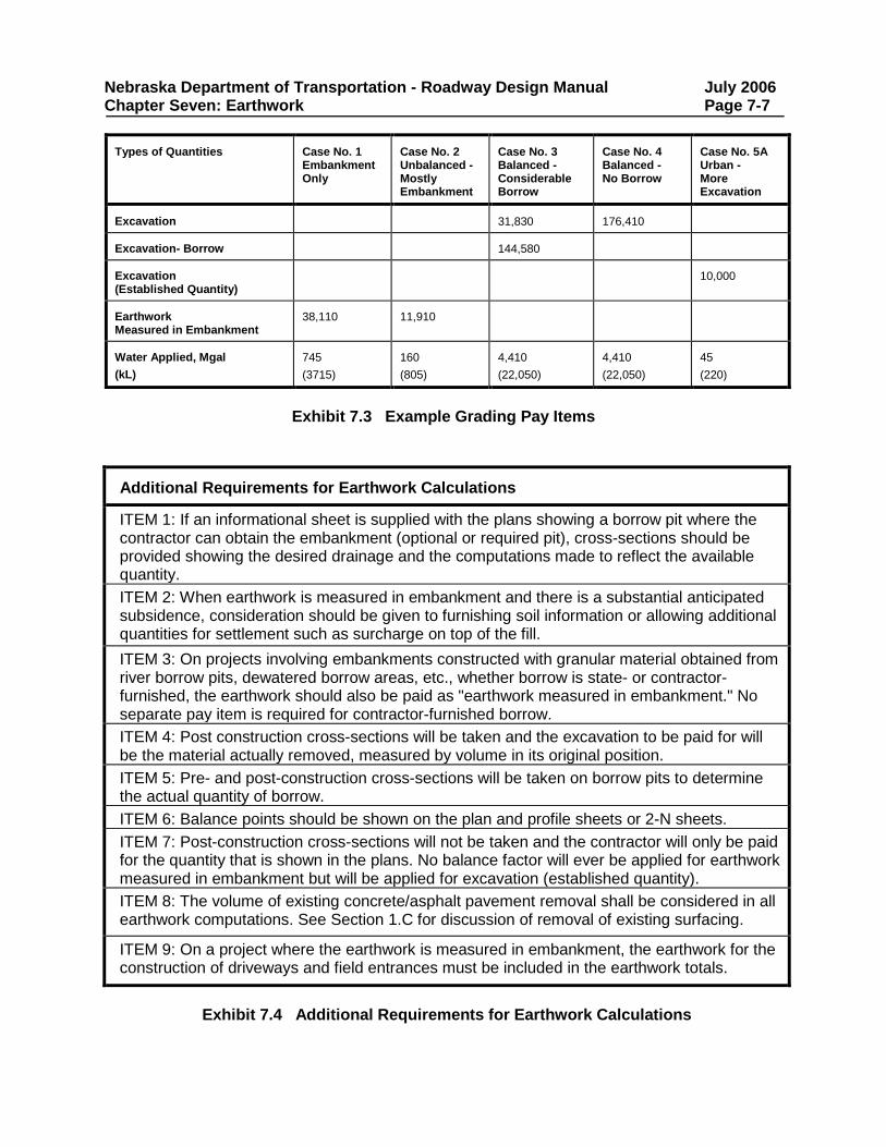
Types of Quantities
Case No. 1 Embankment Only
Case No. 2 Unbalanced - Mostly Embankment
Case No. 3 Balanced - Considerable Borrow
Case No. 4 Balanced - No Borrow
Case No. 5A Urban - More Excavation
Excavation
31,830
176,410
Excavation- Borrow
144,580
Excavation (Established Quantity)
10,000
Earthwork Measured in Embankment
38,110
11,910
Water Applied, Mgal (kL)
745 (3715)
160 (805)
4,410 (22,050)
4,410 (22,050)
45 (220)
Exhibit 7.3 Example Grading Pay Items
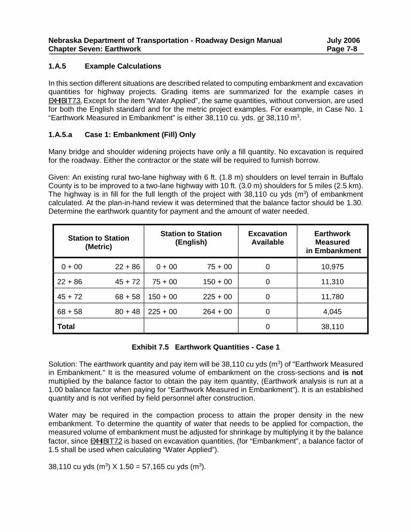
Additional Requirements for Earthwork Calculations
ITEM 1: If an informational sheet is supplied with the plans showing a borrow pit where the contractor can obtain the embankment (optional or required pit), cross-sections should be provided showing the desired drainage and the computations made to reflect the available quantity.
ITEM 2: When earthwork is measured in embankment and there is a substantial anticipated subsidence, consideration should be given to furnishing soil information or allowing additional quantities for settlement such as surcharge on top of the fill.
ITEM 3: On projects involving embankments constructed with granular material obtained from river borrow pits, dewatered borrow areas, etc., whether borrow is state- or contractor- furnished, the earthwork should also be paid as "earthwork measured in embankment." No separate pay item is required for contractor-furnished borrow.
ITEM 4: Post construction cross-sections will be taken and the excavation to be paid for will be the material actually removed, measured by volume in its original position.
ITEM 5: Pre- and post-construction cross-sections will be taken on borrow pits to determine the actual quantity of borrow.
ITEM 6: Balance points should be shown on the plan and profile sheets or 2-N sheets.
ITEM 7: Post-construction cross-sections will not be taken and the contractor will only be paid for the quantity that is shown in the plans. No balance factor will ever be applied for earthwork measured in embankment but will be applied for excavation (established quantity).
ITEM 8: The volume of existing concrete/asphalt pavement removal shall be considered in all earthwork computations. See Section 1.C for discussion of removal of existing surfacing.
ITEM 9: On a project where the earthwork is measured in embankment, the earthwork for the construction of driveways and field entrances must be included in the earthwork totals.
Exhibit 7.4 Additional Requirements for Earthwork Calculations
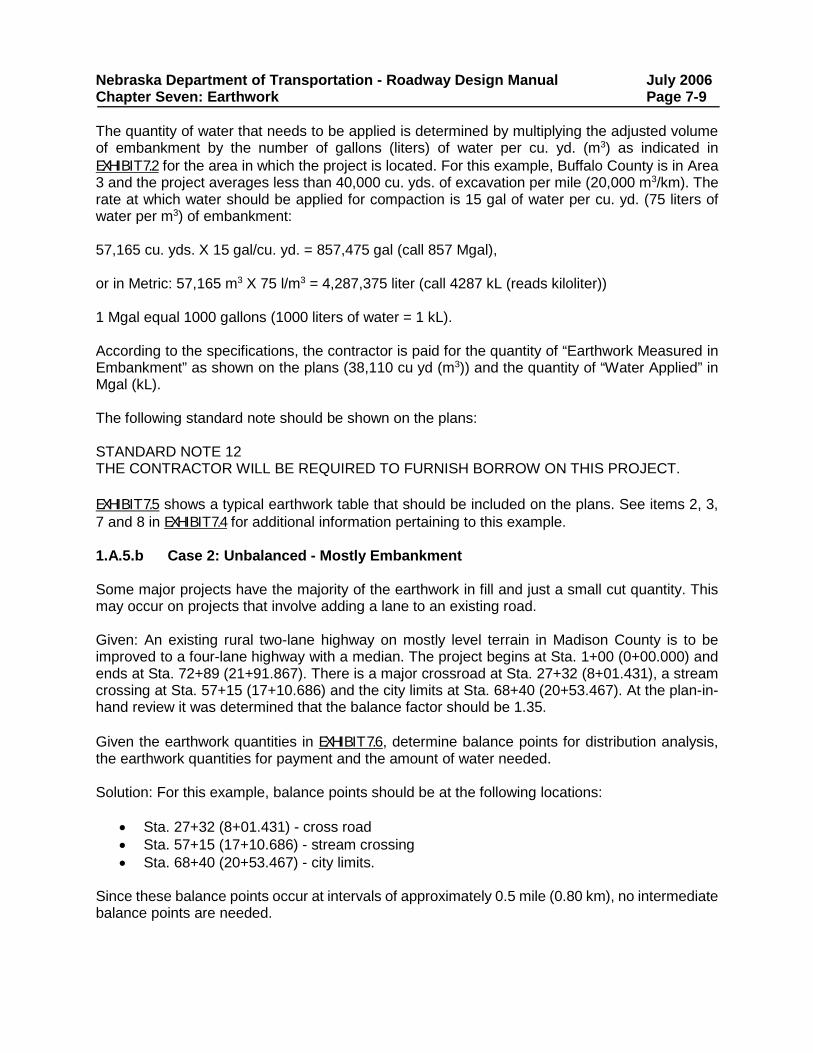
Nebraska Department of Transportation - Roadway Design Manual July 2006 Chapter Seven: Earthwork Page 7-8 1.A.5 Example Calculations In this section different situations are described related to computing embankment and excavation quantities for highway projects. Grading items are summarized for the example cases in EXHIBIT 7.3. Except for the item “Water Applied”, the same quantities, without conversion, are used for both the English standard and for the metric project examples. For example, in Case No. 1 “Earthwork Measured in Embankment” is either 38,110 cu. yds. or 38,110 m3. 1.A.5.a Case 1: Embankment (Fill) Only Many bridge and shoulder widening projects have only a fill quantity. No excavation is required for the roadway. Either the contractor or the state will be required to furnish borrow. Given: An existing rural two-lane highway with 6 ft. (1.8 m) shoulders on level terrain in Buffalo County is to be improved to a two-lane highway with 10 ft. (3.0 m) shoulders for 5 miles (2.5 km). The highway is in fill for the full length of the project with 38,110 cu yds (m3) of embankment calculated. At the plan-in-hand review it was determined that the balance factor should be 1.30. Determine the earthwork quantity for payment and the amount of water needed.
Station to Station
(Metric)
Station to Station
(English)
Excavation Available
Earthwork Measured
in Embankment 0 + 00 22 + 86
0 + 00 75 + 00
0
10,975
22 + 86 45 + 72
75 + 00 150 + 00
0
11,310
45 + 72 68 + 58
150 + 00 225 + 00
0
11,780
68 + 58 80 + 48
225 + 00 264 + 00
0
4,045
Total
0
38,110
Exhibit 7.5 Earthwork Quantities - Case 1
Solution: The earthwork quantity and pay item will be 38,110 cu yds (m3) of "Earthwork Measured in Embankment." It is the measured volume of embankment on the cross-sections and is not multiplied by the balance factor to obtain the pay item quantity, (Earthwork analysis is run at a 1.00 balance factor when paying for “Earthwork Measured in Embankment”). It is an established quantity and is not verified by field personnel after construction. Water may be required in the compaction process to attain the proper density in the new embankment. To determine the quantity of water that needs to be applied for compaction, the measured volume of embankment must be adjusted for shrinkage by multiplying it by the balance factor, since EXHIBIT 7.2 is based on excavation quantities, (for “Embankment”, a balance factor of 1.5 shall be used when calculating “Water Applied”). 38,110 cu yds (m3) X 1.50 = 57,165 cu yds (m3).
Nebraska Department of Transportation - Roadway Design Manual July 2006 Chapter Seven: Earthwork Page 7-9 The quantity of water that needs to be applied is determined by multiplying the adjusted volume of embankment by the number of gallons (liters) of water per cu. yd. (m3) as indicated in EXHIBIT 7.2 for the area in which the project is located. For this example, Buffalo County is in Area 3 and the project averages less than 40,000 cu. yds. of excavation per mile (20,000 m3/km). The rate at which water should be applied for compaction is 15 gal of water per cu. yd. (75 liters of water per m3) of embankment: 57,165 cu. yds. X 15 gal/cu. yd. = 857,475 gal (call 857 Mgal), or in Metric: 57,165 m3 X 75 l/m3 = 4,287,375 liter (call 4287 kL (reads kiloliter)) 1 Mgal equal 1000 gallons (1000 liters of water = 1 kL). According to the specifications, the contractor is paid for the quantity of “Earthwork Measured in Embankment” as shown on the plans (38,110 cu yd (m3)) and the quantity of “Water Applied” in Mgal (kL). The following standard note should be shown on the plans: STANDARD NOTE 12 THE CONTRACTOR WILL BE REQUIRED TO FURNISH BORROW ON THIS PROJECT. EXHIBIT 7.5 shows a typical earthwork table that should be included on the plans. See items 2, 3, 7 and 8 in EXHIBIT 7.4 for additional information pertaining to this example. 1.A.5.b Case 2: Unbalanced - Mostly Embankment Some major projects have the majority of the earthwork in fill and just a small cut quantity. This may occur on projects that involve adding a lane to an existing road. Given: An existing rural two-lane highway on mostly level terrain in Madison County is to be improved to a four-lane highway with a median. The project begins at Sta. 1+00 (0+00.000) and ends at Sta. 72+89 (21+91.867). There is a major crossroad at Sta. 27+32 (8+01.431), a stream crossing at Sta. 57+15 (17+10.686) and the city limits at Sta. 68+40 (20+53.467). At the plan-in-hand review it was determined that the balance factor should be 1.35. Given the earthwork quantities in EXHIBIT 7.6, determine balance points for distribution analysis, the earthwork quantities for payment and the amount of water needed. Solution: For this example, balance points should be at the following locations:
• Sta. 27+32 (8+01.431) - cross road • Sta. 57+15 (17+10.686) - stream crossing • Sta. 68+40 (20+53.467) - city limits.
Since these balance points occur at intervals of approximately 0.5 mile (0.80 km), no intermediate balance points are needed.
Nebraska Department of Transportation - Roadway Design Manual July 2006 Chapter Seven: Earthwork Page 7-10 Station to Station (English)
Station to Station (Metric)
Excavation Available
Earthwork Measured
in Embankment 1+00 27+32
0+00.000 8+01.431
1,050
3,520
27+32 57+15
8+01.431 17+10.686
500
5,340
57+15 68+40
17+10.686 20+53.467
0
2,640
68+40 72+89
20+53.467 21+91.867
0
415
Total (cu yds (m3))
1,550
11,915
Exhibit 7.6 Earthwork Quantities - Case 2
The pay item will be 11,915 cu. yds. (m3) of "Earthwork Measured in Embankment" of which 1,550 cu. yds. (m3) will be excavated as shown on cross-sections (See Case 1, which explains “Earthwork Measured in Embankment” in greater detail). For the amount of water that needs to be applied for compaction, the embankment quantity needs to be adjusted for shrinkage by multiplying it by the balance factor: 11,915 cu. yds. X 1.35 = 16,085 cu. yds. (m3) The quantity of water that needs to be applied is determined by multiplying the adjusted volume of embankment by the number of gallons (liters) of water per cu. yd. (m3) as indicated in EXHIBIT 7.2 for the area in which the project is located. For this example, Madison County is in Area 2 and the project averages less than 40,000 cu. yds. per mile (20,000 m3/km) of excavation. The rate at which water should be applied for compaction is 10 gallons (50 liters) of water per cu. yd. (m3) of embankment: 16,085 cu. yds. X 10 gal/cu. yd. = 160,850 gal (call 161 Mgal.) or in Metric: 16,085 m3 X 50 l/m3 = 804,250 liters (call 804 kL) In this case, the following standard note should be shown on the plans: STANDARD NOTE 12 THE CONTRACTOR WILL BE REQUIRED TO FURNISH BORROW ON THIS PROJECT. EXHIBIT 7.6 shows an example of an earthwork table that shall be included on the plans. See items 2, 3, 7 and 8 in EXHIBIT 7.4 for additional information pertaining to this example. 1.A.5.c Case 3: Balanced – Considerable Borrow Furnished by Contractor Often on major grading projects, such as adding lanes to an existing highway, the earthwork is paid as excavation even though a considerable amount of contractor-furnished borrow is required to complete the project.
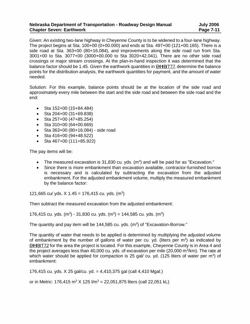
Nebraska Department of Transportation - Roadway Design Manual July 2006 Chapter Seven: Earthwork Page 7-11 Given: An existing two-lane highway in Cheyenne County is to be widened to a four-lane highway. The project begins at Sta. 100+00 (0+00.000) and ends at Sta. 497+00 (121+00.165). There is a side road at Sta. 363+00 (80+16.084), and improvements along the side road run from Sta. 3001+00 to Sta. 3077+00 (3000+00.000 to Sta 3020+42.041). There are no other side road crossings or major stream crossings. At the plan-in-hand inspection it was determined that the balance factor should be 1.45. Given the earthwork quantities in EXHIBIT 7.7, determine the balance points for the distribution analysis, the earthwork quantities for payment, and the amount of water needed. Solution: For this example, balance points should be at the location of the side road and approximately every mile between the start and the side road and between the side road and the end:
• Sta 152+00 (15+84.484) • Sta 204+00 (31+69.838) • Sta 257+00 (47+85.254) • Sta 310+00 (64+00.669) • Sta 363+00 (80+16.084) - side road • Sta 416+00 (94+48.522) • Sta 467+00 (111+85.922)
The pay items will be:
• The measured excavation is 31,830 cu. yds. (m3) and will be paid for as "Excavation." • Since there is more embankment than excavation available, contractor-furnished borrow
is necessary and is calculated by subtracting the excavation from the adjusted embankment. For the adjusted embankment volume, multiply the measured embankment by the balance factor:
121,665 cu/ yds. X 1.45 = 176,415 cu. yds. (m3) Then subtract the measured excavation from the adjusted embankment: 176,415 cu. yds. (m3) - 31,830 cu. yds. (m3) = 144,585 cu. yds. (m3) The quantity and pay item will be 144,585 cu. yds. (m3) of "Excavation-Borrow." The quantity of water that needs to be applied is determined by multiplying the adjusted volume of embankment by the number of gallons of water per cu. yd. (liters per m3) as indicated by EXHIBIT 7.2 for the area the project is located. For this example, Cheyenne County is in Area 4 and the project averages less than 40,000 cu. yds. of excavation per mile (20,000 m3/km). The rate at which water should be applied for compaction is 25 gal/ cu. yd. (125 liters of water per m3) of embankment: 176,415 cu. yds. X 25 gal/cu. yd. = 4,410,375 gal (call 4,410 Mgal.) or in Metric: 176,415 m3 X 125 l/m3 = 22,051,875 liters (call 22,051 kL)
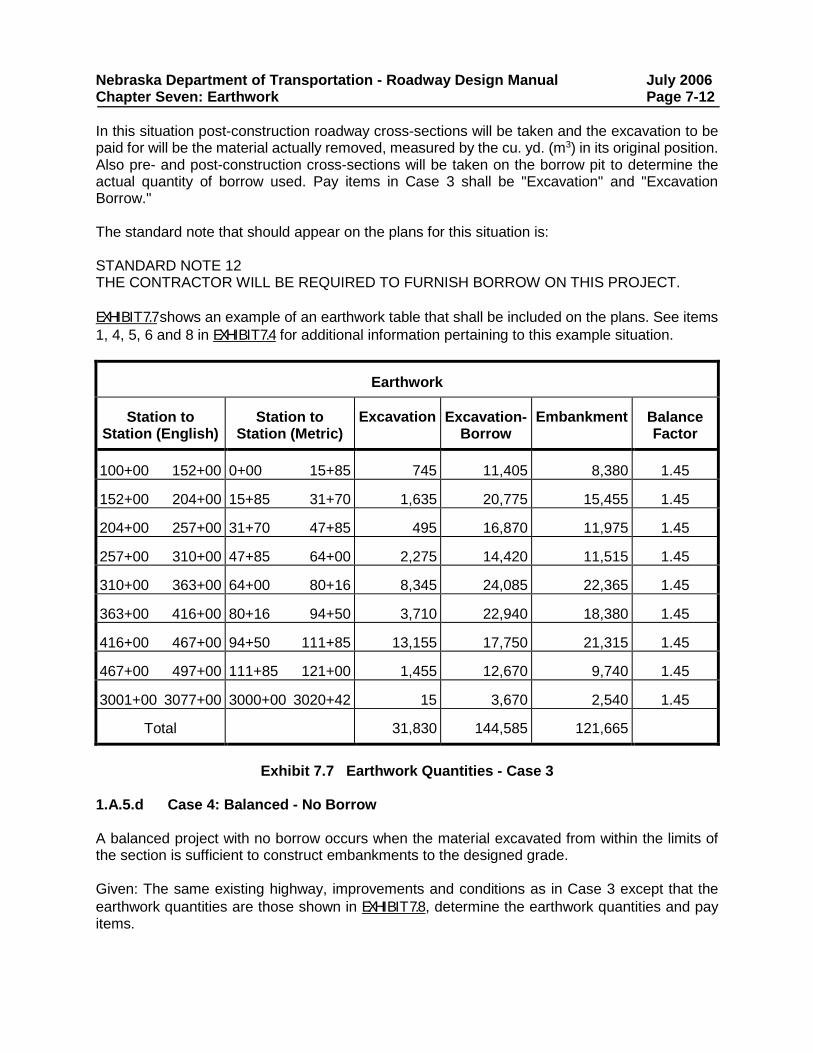
Nebraska Department of Transportation - Roadway Design Manual July 2006 Chapter Seven: Earthwork Page 7-12 In this situation post-construction roadway cross-sections will be taken and the excavation to be paid for will be the material actually removed, measured by the cu. yd. (m3) in its original position. Also pre- and post-construction cross-sections will be taken on the borrow pit to determine the actual quantity of borrow used. Pay items in Case 3 shall be "Excavation" and "Excavation Borrow." The standard note that should appear on the plans for this situation is: STANDARD NOTE 12 THE CONTRACTOR WILL BE REQUIRED TO FURNISH BORROW ON THIS PROJECT. EXHIBIT 7.7 shows an example of an earthwork table that shall be included on the plans. See items 1, 4, 5, 6 and 8 in EXHIBIT 7.4 for additional information pertaining to this example situation.
Earthwork
Station to Station (English)
Station to
Station (Metric)
Excavation
Excavation-
Borrow
Embankment
Balance Factor
100+00 152+00
0+00 15+85
745
11,405
8,380
1.45
152+00 204+00
15+85 31+70
1,635
20,775
15,455
1.45
204+00 257+00
31+70 47+85
495
16,870
11,975
1.45
257+00 310+00
47+85 64+00
2,275
14,420
11,515
1.45
310+00 363+00
64+00 80+16
8,345
24,085
22,365
1.45
363+00 416+00
80+16 94+50
3,710
22,940
18,380
1.45
416+00 467+00
94+50 111+85
13,155
17,750
21,315
1.45
467+00 497+00
111+85 121+00
1,455
12,670
9,740
1.45
3001+00 3077+00
3000+00 3020+42
15
3,670
2,540
1.45
Total
31,830
144,585
121,665
Exhibit 7.7 Earthwork Quantities - Case 3
1.A.5.d Case 4: Balanced - No Borrow A balanced project with no borrow occurs when the material excavated from within the limits of the section is sufficient to construct embankments to the designed grade. Given: The same existing highway, improvements and conditions as in Case 3 except that the earthwork quantities are those shown in EXHIBIT 7.8, determine the earthwork quantities and pay items.
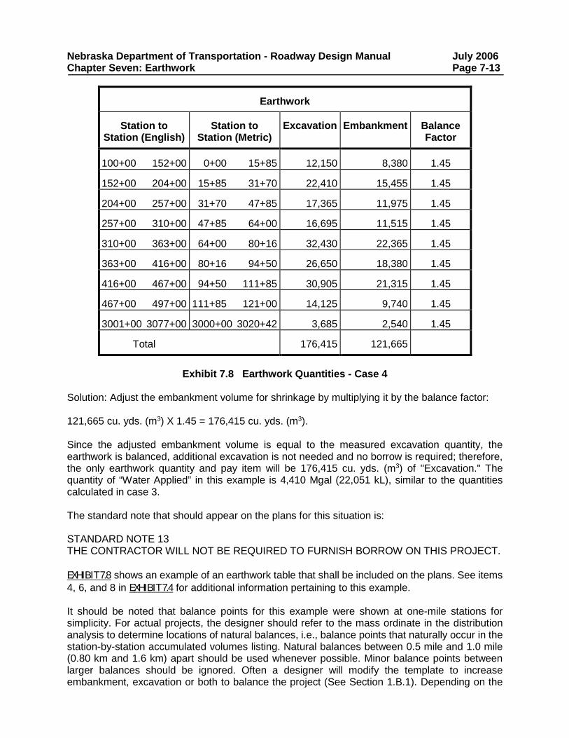
Nebraska Department of Transportation - Roadway Design Manual July 2006 Chapter Seven: Earthwork Page 7-13
Earthwork
Station to
Station (English)
Station to
Station (Metric)
Excavation
Embankment
Balance Factor
100+00 152+00
0+00 15+85
12,150
8,380
1.45
152+00 204+00
15+85 31+70
22,410
15,455
1.45
204+00 257+00
31+70 47+85
17,365
11,975
1.45
257+00 310+00
47+85 64+00
16,695
11,515
1.45
310+00 363+00
64+00 80+16
32,430
22,365
1.45
363+00 416+00
80+16 94+50
26,650
18,380
1.45
416+00 467+00
94+50 111+85
30,905
21,315
1.45
467+00 497+00
111+85 121+00
14,125
9,740
1.45
3001+00 3077+00
3000+00 3020+42
3,685
2,540
1.45
Total
176,415
121,665
Exhibit 7.8 Earthwork Quantities - Case 4
Solution: Adjust the embankment volume for shrinkage by multiplying it by the balance factor: 121,665 cu. yds. (m3) X 1.45 = 176,415 cu. yds. (m3). Since the adjusted embankment volume is equal to the measured excavation quantity, the earthwork is balanced, additional excavation is not needed and no borrow is required; therefore, the only earthwork quantity and pay item will be 176,415 cu. yds. (m3) of "Excavation." The quantity of “Water Applied” in this example is 4,410 Mgal (22,051 kL), similar to the quantities calculated in case 3. The standard note that should appear on the plans for this situation is: STANDARD NOTE 13 THE CONTRACTOR WILL NOT BE REQUIRED TO FURNISH BORROW ON THIS PROJECT. EXHIBIT 7.8 shows an example of an earthwork table that shall be included on the plans. See items 4, 6, and 8 in EXHIBIT 7.4 for additional information pertaining to this example. It should be noted that balance points for this example were shown at one-mile stations for simplicity. For actual projects, the designer should refer to the mass ordinate in the distribution analysis to determine locations of natural balances, i.e., balance points that naturally occur in the station-by-station accumulated volumes listing. Natural balances between 0.5 mile and 1.0 mile (0.80 km and 1.6 km) apart should be used whenever possible. Minor balance points between larger balances should be ignored. Often a designer will modify the template to increase embankment, excavation or both to balance the project (See Section 1.B.1). Depending on the
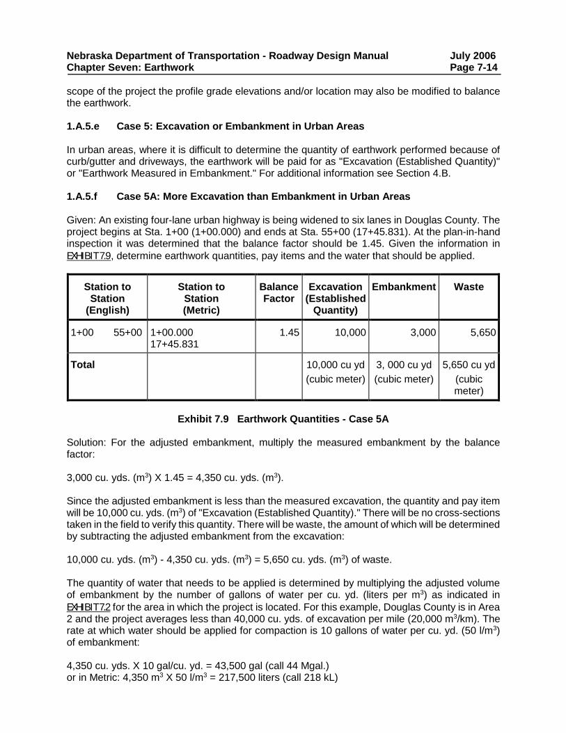
Nebraska Department of Transportation - Roadway Design Manual July 2006 Chapter Seven: Earthwork Page 7-14 scope of the project the profile grade elevations and/or location may also be modified to balance the earthwork. 1.A.5.e Case 5: Excavation or Embankment in Urban Areas In urban areas, where it is difficult to determine the quantity of earthwork performed because of curb/gutter and driveways, the earthwork will be paid for as "Excavation (Established Quantity)" or "Earthwork Measured in Embankment." For additional information see Section 4.B. 1.A.5.f Case 5A: More Excavation than Embankment in Urban Areas Given: An existing four-lane urban highway is being widened to six lanes in Douglas County. The project begins at Sta. 1+00 (1+00.000) and ends at Sta. 55+00 (17+45.831). At the plan-in-hand inspection it was determined that the balance factor should be 1.45. Given the information in EXHIBIT 7.9, determine earthwork quantities, pay items and the water that should be applied.
Station to Station
(English)
Station to
Station (Metric)
Balance Factor
Excavation (Established Quantity)
Embankment
Waste
1+00 55+00
1+00.000 17+45.831
1.45
10,000
3,000
5,650
Total
10,000 cu yd (cubic meter)
3, 000 cu yd (cubic meter)
5,650 cu yd
(cubic meter)
Exhibit 7.9 Earthwork Quantities - Case 5A
Solution: For the adjusted embankment, multiply the measured embankment by the balance factor: 3,000 cu. yds. (m3) X 1.45 = 4,350 cu. yds. (m3). Since the adjusted embankment is less than the measured excavation, the quantity and pay item will be 10,000 cu. yds. (m3) of "Excavation (Established Quantity)." There will be no cross-sections taken in the field to verify this quantity. There will be waste, the amount of which will be determined by subtracting the adjusted embankment from the excavation: 10,000 cu. yds. (m3) - 4,350 cu. yds. (m3) = 5,650 cu. yds. (m3) of waste. The quantity of water that needs to be applied is determined by multiplying the adjusted volume of embankment by the number of gallons of water per cu. yd. (liters per m3) as indicated in EXHIBIT 7.2 for the area in which the project is located. For this example, Douglas County is in Area 2 and the project averages less than 40,000 cu. yds. of excavation per mile (20,000 m3/km). The rate at which water should be applied for compaction is 10 gallons of water per cu. yd. (50 l/m3) of embankment: 4,350 cu. yds. X 10 gal/cu. yd. = 43,500 gal (call 44 Mgal.) or in Metric: 4,350 m3 X 50 l/m3 = 217,500 liters (call 218 kL)
Nebraska Department of Transportation - Roadway Design Manual July 2006 Chapter Seven: Earthwork Page 7-15 The following notes should be shown on the plans: STANDARD NOTE 13 THE CONTRACTOR WILL NOT BE REQUIRED TO FURNISH BORROW ON THIS PROJECT. STANDARD NOTE 14 THE CONTRACTOR WILL BE REQUIRED TO FURNISH WASTE AREAS FOR EXCESS EXCAVATION ON THIS PROJECT. See item 8 in EXHIBIT 7.4 for additional information pertaining to this example. 1.A.5.g Case 5B: More Embankment than Excavation in Urban Areas Use the procedures described in Section 1.A.5.b. 1.B Borrow Pits and Waste Sites Borrow pits are sources of approved material required for the construction of embankments or other portions of earthwork requirements. Waste sites are areas established for the disposal of excess excavation or unsuitable materials. The following items should be considered for state-furnished borrow pits and waste sites on new and reconstructed projects:
• The designer should consider all available options to balance the project or reduce borrow and/or waste.
• When borrow pits and/or waste sites are unavoidable, they should be discussed on the plan-in-hand field inspection.
• Locations for borrow and waste sites should be determined before L.O.C. plans (Activity #5500) are transmitted to Right-of-Way Design.
• Borrow pits and waste sites require clearance for historical and environmental impacts. If there are any changes to these sites after the R.O.W. Appraisal Plans have been designed the roadway designer shall notify the State Historical Preservation Officer and the Environmental Section Manager in the Project Development Division, (See Chapter Thirteen: Planning and Project Development, Section 4).
1.B.1 Alternatives to Providing Borrow or Waste Sites NDOT prefers that borrow and waste sites not be used if there are alternatives available that eliminate the need for borrow/waste sites.
Nebraska Department of Transportation - Roadway Design Manual July 2006 Chapter Seven: Earthwork Page 7-16 1.B.1.a Borrow Alternatives
• Daylighting: Daylighting is the flattening of the roadway backslope so that it intersects the natural ground at a lower elevation than the normal backslope. See Chapter Six: The Typical Roadway Cross-Section, Section 10.H.
• Ditch Widening: If adequate right-of-way is available ditches may be widened to provide additional excavation. When ditch widening is used it should be uniform and consistent over long stretches with gradual transitions between widths.
• Flattening Backslopes: If adequate right-of-way is available backslopes on ditches may be flattened. As with ditch widening, flattening should be uniform and consistent over long stretches with gradual transitions between slope changes. Backslopes in cut sections may be flattened from 3:1 to a flatter slope up to 4:1.
• Special Ditches: A special ditch is any ditch that varies in slope or depth from the standard ditch shown on the typical cross-section. If adequate right-of-way is available, special ditches may be designed to increase the available excavation as well as to provide better drainage.
• Modify Alignments: The horizontal and vertical alignments may be shifted along the entire length of the project or in isolated areas to help eliminate the need for borrow.
1.B.1.b Waste Alternatives
• Flattening Fill and Foreslopes: If adequate right-of-way is available fill and foreslopes may be flattened from 6:1 up to 10:1 to help eliminate the need to waste material. Flattened slopes should be uniform and consistent over long stretches, with gradual transitions between changes in slopes. The designer should try to increase embankment while keeping the required additional right-of-way to a minimum.
• Fill Low Areas: Additional excavation may be placed in low areas outside of the construction limits and within the right-of-way, provided that the fill does not adversely affect drainage or aesthetic conditions. Wetlands should be avoided (See Chapter Thirteen: Planning and Project Development, Section 4.B).
• Modify Alignments: The horizontal and vertical alignments may be shifted along the entire length of the project or in isolated areas to help eliminate waste.
1.B.2 Borrow Pit Restoration If state-owned land is used for a borrow pit, restoration is required. See the Standard Specifications for Highway Construction, (Reference 7.2), Section 208. 1.C Removal of Existing Surfacing If surfacing material is to be salvaged, removal is generally a pay item, (See Chapter Eight: Surfacing, Section 5.B for further information). 1.C.1 Rural Projects The existing asphalt surface on full grading projects will normally be salvaged. Existing concrete surfacing may also be salvaged. The roadway designer should check with the Materials and Research Division during the pre-design of the project to find out the depth, width and length of the material that is to be salvaged. The preliminary cross-sections should then be recoded to
Nebraska Department of Transportation - Roadway Design Manual July 2006 Chapter Seven: Earthwork Page 7-17 reflect the void left by the existing surface that is to be removed. The removal of this material will be paid for directly as a separate pay item. If the existing asphalt surface is not to be salvaged, this surfacing may be placed in the outer slopes of the embankment 1 ft. (300 mm) below the finished shoulders and foreslope. No deductions to the earthwork quantities are required for the volume occupied by this surfacing. If the existing surfacing is concrete and is not to be salvaged but is to be removed, the roadway designer should deduct the volume occupied by this surfacing in computing the earthwork balance, and the removal should be paid for directly. If the concrete is to be removed, crushed and replaced as foundation course, the removal is subsidiary to the crushed concrete foundation course item as long as the crushed concrete is solely used for foundation course (i.e., has one use only). When less than 3 ft. (1 m) of embankment is to be placed over an existing concrete pavement or base course, the existing surfacing shall be removed and paid for. When the embankment is greater than 3 ft. (1 m), the grading contractor shall break the concrete into pieces of approximately 4 sq. ft. (0.4 m2) in size and leave them in place. This activity is paid for as the item, "breaking pavement." 1.C.2 Urban Projects Normally there is no place to bury existing surface material on urban projects, therefore removal is usually specified. In this case the roadway designer should deduct the volume occupied by this surfacing in computing the earthwork balance, and the removal should be paid for directly. Alternatively, asphalt may be milled and salvaged. In this case, it is paid for as milling and the quantity is deducted from the earthwork. If the project covers both rural and urban areas, the plans shall show the physical limits of asphalt removal to be paid for and the physical limits of asphalt removal, which is subsidiary to excavation. 2. STAGED CONSTRUCTION/PHASING A distribution analysis shall be done for each separate phase of construction for a project. Cross-section cut and fill areas should reflect the staged construction and should correspond with the distribution analysis performed. Projects with phased construction, expressway projects for example, will show earthwork quantities on the cross-sections for each phase of construction. This distribution analysis shall be for information only, unless the given quantities are “Established Quantities”. In cases where the project requires more than one construction season, cover crop seeding will be calculated for each phase of construction. The 2N sheet will show the quantity of cover crop seeding required for each phase. The 2N sheet will also have a table showing the earthwork quantities for each phase of construction. Although it is the roadway designer's responsibility to provide reasonable phasing, the actual construction phasing is left to the discretion of the contractor with the approval of the Project Engineer. For additional information see Chapter Fourteen: Traffic, Section 6.
Nebraska Department of Transportation - Roadway Design Manual July 2006 Chapter Seven: Earthwork Page 7-18 3. MISCELLANEOUS EARTHWORK CONSIDERATIONS 3.A Unsuitable Materials Unsuitable materials are materials that are inappropriate for use in the embankment. They include rock, organic muck or any foreign objects, such as garbage, car bodies, etc. The Soil and Situation Report will list the location, type of material and treatments for the unsuitable material found. Often rock can be used in the toe of the fill. If organic muck is encountered unexpectedly by the contractor, a change order, (a written order to the contractor covering changes in the contract), will be necessary to excavate the unsuitable material and to haul in acceptable material to replace the unsuitable material, (See Chapter Thirteen: Planning and Project Development: Section 4.H for additional information). 3.B Contaminated Soils See Chapter Thirteen: Planning and Project Development: Section 4.H.3. 3.C Guardrail Additional embankment and grading may be required for the installation of guardrail. This earthwork is not considered subsidiary and should be calculated and included in earthwork quantities. Refer to Chapter Nine: Guardrail and Roadside Barriers, Section 3.F, and the guardrail special plans (Standard/Special Plans Book, Reference 7.3) (http://www.roads.nebraska.gov/business-center/design-consultant/stand-spec-manual/). 3.D Driveways The method of handling the earthwork required for driveway construction varies according to the pay item, as shown below:
• “Excavation” or “Excavation-Borrow”: The designer does not need to calculate the earthwork required to build the drives. The contractor will be paid for any necessary additional excavation as it is measured on the project.
• “Earthwork Measured in Embankment” or “Excavation (Established Quantity)”: The designer shall calculate and add to the earthwork quantities all earthwork required to build all intersections, drives, field entrances and earth dikes.
3.E Settlement When embankment is placed on existing ground, the weight of the embankment causes the existing ground to settle and thus the embankment also will settle. An excess of embankment may be placed to overcome the effects of consolidation. The Embankment Foundation Report (See Section 6.C) will usually indicate when additional embankment is necessary. The designer shall coordinate the design of the project in areas of embankment settlement with the Soils Engineer in the Materials and Research Division.
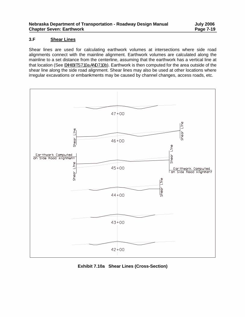
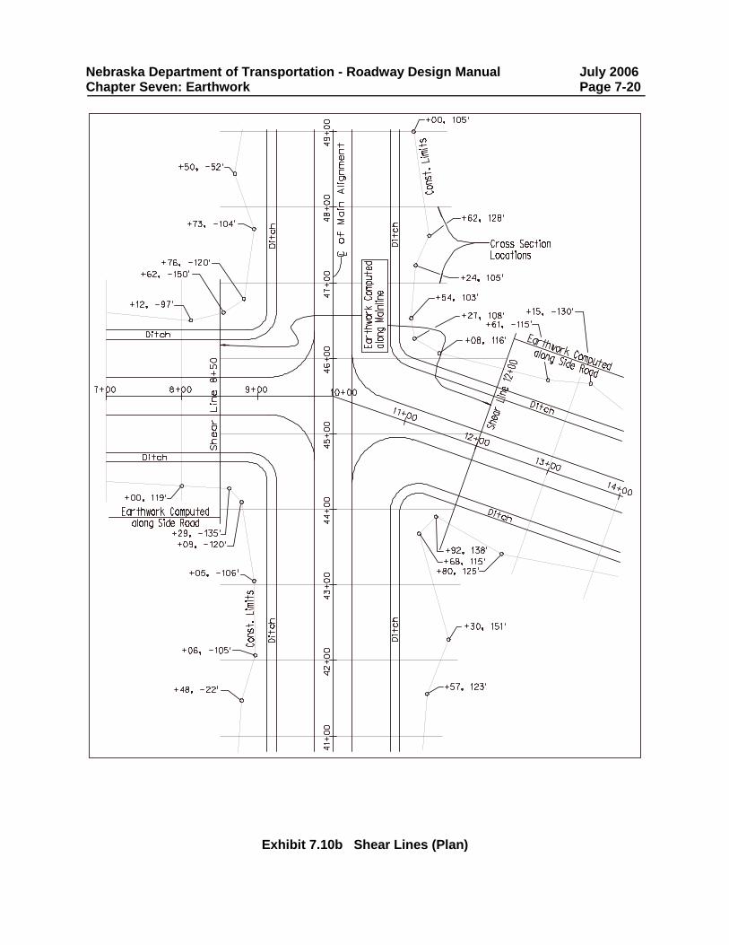
Nebraska Department of Transportation - Roadway Design Manual July 2006 Chapter Seven: Earthwork Page 7-19 3.F Shear Lines Shear lines are used for calculating earthwork volumes at intersections where side road alignments connect with the mainline alignment. Earthwork volumes are calculated along the mainline to a set distance from the centerline, assuming that the earthwork has a vertical line at that location (See EXHIBITS 7.10a AND 7.10b). Earthwork is then computed for the area outside of the shear line along the side road alignment. Shear lines may also be used at other locations where irregular excavations or embankments may be caused by channel changes, access roads, etc.
Exhibit 7.10a Shear Lines (Cross-Section)
Nebraska Department of Transportation - Roadway Design Manual July 2006 Chapter Seven: Earthwork Page 7-20
Exhibit 7.10b Shear Lines (Plan)
Nebraska Department of Transportation - Roadway Design Manual July 2006 Chapter Seven: Earthwork Page 7-21 4. METHODS OF PAYMENT 4.A “Excavation” and “Excavation-Borrow” “Excavation” and “Excavation-Borrow” are the preferred method of earthwork payment on projects with large quantities. Generally, grading projects that average more than 5000 cu. yds. per mile (2375 m3 per km) will be paid for as “Excavation”. On major grading projects where the earthwork is paid for as “Excavation” and where the contractor is required to furnish borrow, the excavation quantity within the right-of-way and the easements shall be calculated separately from what the contractor will furnish. A separate pay item, “Excavation-Borrow”, will be used for the contractor furnished borrow. The quantities for these pay items will be measured in the field and then calculated for payment. 4.B “Established Quantities” Sometimes it is difficult to determine in the field the quantity of earthwork performed. In this situation earthwork should be paid for as an established quantity, which is determined by roadway design from the cross-sections. This measured “established” quantity is used for payment of earthwork instead of field-measured quantities. Established quantities can be in excavation or embankment. This method of payment is most often used for urban roadway projects and for temporary roadways. In the Omaha area and on urban projects where the contractor will be required to furnish borrow the earthwork pay item will be an “Established Quantity”, with no separate pay item for contractor furnished borrow. 4.B.1 “Earthwork Measured in Embankment” and “Excavation (Established Quantity)” “Earthwork Measured in Embankment” is paid for according to the embankment measured from the cross-sections. It does not include excavation, nor is it adjusted by a balance factor. When earthwork is measured in embankment and there is a substantial anticipated settlement, consideration should be given to furnishing soil information or allowing additional quantities for the settlement. This method of payment is typically used on projects that have embankment only or on projects that are mostly embankment with very little excavation. On projects involving embankments constructed with granular material obtained from river borrow pits, dewatered borrow areas, etc. (whether borrow is state or contractor-furnished), the earthwork should be paid for as “Earthwork Measured in Embankment”, with no separate pay item for contractor-furnished borrow. “Excavation (Established Quantity)” is paid for according to the measured excavation from the cross-sections. A balance factor is included if there is any calculated embankment. 4.C Roadway Grading For roadways constructed with only a typical section and without cross-sections, the appropriate pay item is “Roadway Grading”. “Roadway Grading” consists of the furnishing, excavating, loading, hauling, placing, compacting, and finishing of all materials necessary for the completion of the roadway, including its embankments, intersections, driveways, and approaches as shown in the plans. For further information see the Standard Specifications for Highway Construction, (Reference 7.2), Section 206.
Nebraska Department of Transportation - Roadway Design Manual July 2006 Chapter Seven: Earthwork Page 7-22 4.D Added Quantities Earthwork for earth dikes, large drives and intersections should be added to the computer-generated quantities as an added quantity. 4.E Subsidiary Earthwork Subsidiary earthwork is earthwork that is not paid for directly but is included in other earthwork or other construction items.
• Often on small urban projects with small amounts of earthwork all earthwork is made subsidiary.
• The construction of small earth dikes is subsidiary to the pay item “Excavation”. • Earthwork for the construction of larger earth dikes should be calculated as “Earthwork
Measured in Embankment” where no balance factor is considered, or they may be built as roadway embankment from a borrow pit, which will be paid for as “Excavation Borrow.”
For further discussion of earthwork payment, refer to the Standard Specifications for Highway Construction, (Reference 7.2). 5. EARTHWORK/CROSS-SECTION CHECK POLICY 5.A General The following checks shall be made on earthwork and cross-section computations.
• Preliminary plans: the Roadway Design Unit Head will review the earthwork checklist with the roadway designer and supervisor and ask special questions if applicable on plan-in-hand.
• Functional plans: the Roadway Design Unit Head, designer and supervisor will review the checklist again and note anything that will need to change from the plan-in-hand plans.
• Limits of construction plans: The roadway designer, supervisor, and Roadway Design Unit Head should double check earthwork.
• Final plans submittal: 1. Check the computer generated earthwork output. 2. Check the earthwork data (stick-up) sheets. 3. Final cross-sections: transfer work sheet data to final cross-sections. 4. Check the field books.
Refer to EXHIBIT O of the Design Process Outline, (Reference 7.4), for the earthwork checklist (http://www.roads.nebraska.gov/media/6761/design-process-outline.pdf).
Nebraska Department of Transportation - Roadway Design Manual July 2006 Chapter Seven: Earthwork Page 7-23 6. SOIL, SUBGRADE AND SITUATION REPORTS The soil, subgrade and materials surveys are essential to preliminary engineering for location and design purposes. Information about the distribution of soils and groundwater conditions is required input for a reasonable and economic roadway design. The Materials and Research Division reports provide pertinent information on the following aspects of highway design:
• Location of the grade line, both vertically and horizontally. • Location and selection of borrow material for fills and subgrade treatment. • Design and location of ditches and underdrains. • Design of the roadway section. • Need for subgrade treatment and type of treatment required. • Location of local sources of construction material. • Selection of the surface type and its design (See Chapter Eight: Surfacing, Section 1).
6.A Soil Survey/Soil and Situation Report The soil survey will research the soil profile, soil horizons and the uniformity of the profile throughout the project, soil compaction and other soils characteristics by station, the water table condition and other concerns such as underground wet zones. The Materials and Research Division uses the following criteria to determine the minimum finished grade elevation above the expected high water table:
• 4 ft. (1.2 m) above the expected high water table if the entire profile is sand. • 7 ft. (2.1 m) above the expected high water table if there is to be silt-clay within 4 ft.
(1.2 m) of the finished grade elevation. 6.A.1 Soil Survey A soil survey is usually performed with preliminary plans, which have the approximate grade line, prior to the final preparation of the grading plans. It usually consists of the research of soils maps, aerial photographs, geology reports and condition reports, preliminary field reconnaissance of the project, previous project reports, soil borings in areas of excavation and embankment, and recordings of water table locations. Laboratory soil tests are made on the samples taken and results are tabulated. 6.A.2 Preliminary Soil and Situation Report If the soil survey reveals a condition that may present problems for the design or construction of a project, a Preliminary Soils and Situation Report is submitted to the Roadway Design Division. The preliminary report usually addresses water table concerns. It may include locations of usable quantities of sand in a silt-clay region or locations of borrow pits. Settlement and unsuitable material issues may also be addressed. Unless there is a big cut or fill, a preliminary report is not normally sent to Roadway Design.
Nebraska Department of Transportation - Roadway Design Manual July 2006 Chapter Seven: Earthwork Page 7-24 6.A.3 Soil and Situation Report The Soil and Situation Report presents the results of the soil survey in a standardized format. It includes the following:
• The location and length of the project. • The topography and drainage situation. • The water table. • The geology of the project area. • Soil horizons and formations. • Soil descriptions, including engineering characteristics. • Recommendations for subgrade treatments. • Compaction requirements.
If selective handling of excavated materials is planned for the project, recommendations for the handling are also included. Selective handling is generally restricted to five general cases:
1. To produce embankment sections of uniform material, i.e., all silt-clay soils or all sandy materials in the upper embankment.
2. To place materials suitable for use in a bituminous sand base course in the upper subgrade.
3. To place highly undesirable materials at depth or in the outer slopes of the embankment. 4. To place select materials over heavy clay materials to reduce moisture problems. 5. To use select granular materials in lieu of a foundation course on Portland cement
concrete pavement projects. The Soil and Situation Report will divide the project, if necessary, into sections of one or more balances according to soil type or other factors. A detailed discussion of soil materials to be excavated is then developed for each section. The selective soil placement notes always reflect the surfacing plans for the project. The soil survey may also identify locations for possible sources of shoulder material, topsoil to support subsequent vegetation or soil binder material. It is the responsibility of the designer to ensure that the recommendations of the Soil and Situation Report, and the resulting design, are detailed on the project plan sheets. 6.B Subgrade Survey/Subgrade and Situation Report 6.B.1 Subgrade Survey The subgrade survey is conducted on previously graded roads for which rigid or flexible pavement is being designed. Its principal objectives are:
• To sectionalize the project according to the type of soil in the upper subgrade. • To locate and explore any portions of the project where the subgrade may be of
questionable stability due to springs, seepage or wet zones. • To evaluate gravel windrow or crust which may have been placed or developed under
traffic with temporary gravel surfacing or clay surfacing. • To obtain a check on the conditions resulting from the selective placement required by the
grading plans.
Nebraska Department of Transportation - Roadway Design Manual July 2006 Chapter Seven: Earthwork Page 7-25 6.B.2 Subgrade and Situation Report The Subgrade and Situation Report is prepared for those projects where there is a period of time between grading and the preparation of paving plans. Whenever grading and paving are let in the same contract, the design of the base and surface courses is based on information obtained from the soil survey. The Subgrade and Situation Report usually contains the following:
• A description of the existing surface conditions. • The proposed construction. • The foundation course requirements. • The existing topography and pedology. • A description of and recommendations for the surface and subsurface drainage. • Compaction requirements. • Any subgrade distress. • Any embankment and/or slope stability problems.
The compaction requirements list will be added to the plans. 6.C Embankment Foundation Report In known areas of poor foundation soils, a field investigation of foundation soils is made by the Soils Mechanics Unit to develop recommendations to minimize settlement and slope stability problems. An Embankment Foundation Report is submitted to the Roadway Design Division to advise of possible adverse conditions and to recommend possible remedies. The two most common solutions to correct settlement problems are:
• Construct surcharges to speed up settlement. • Delay paving until settlement has reached a satisfactory level.
Other possible corrective measures include:
• Use of temporary bituminous paving until settlement has reached a satisfactory level, when permanent paving may be placed.
• Excavation of unsuitable material. • Use of vertical sand drains to speed settlement. • Lower the height of the fill. • Realign the road to avoid the unsuitable area. • Bridging over the unsuitable area.
Nebraska Department of Transportation - Roadway Design Manual July 2006 Chapter Seven: Earthwork Page 7-26 To correct embankment stability problems during and after grading construction, several possible solutions are available (See the Earthwork Engineering Guide, Reference 7.5):
• Require special compaction of the embankment material, e.g., higher minimum density and lower maximum moisture content.
• Flatten side slopes of the embankment from 3:1 to 5:1. • Build berms. • Staged construction, the process of bringing fill up to maximum height in several stages
over a period of time (usually two or more years). • Excavate unsuitable material. • Lower the height of the fill. • Realign the road. • Bridging. • A combination of the above, e.g., special compaction and stage construction.
The recommendations contained in the Embankment Foundation Report, and the resulting design, will be detailed on the project plan sheets.
Nebraska Department of Transportation - Roadway Design Manual July 2006 Chapter Seven: Earthwork Page 7-27 7. REFERENCES 7.1 Nebraska Department of Transportation, Drainage Design and Erosion Control
Manual, Current Edition (http://www.roads.nebraska.gov/business-center/design-consultant/rd-manuals/)
7.2 Nebraska Department of Transportation, Standard Specifications for Highway
Construction, 2017. (http://dot.nebraska.gov/media/10343/2017-specbook.pdf) 7.3 Nebraska Department of Transportation, Standard/Special Plan Book, Current
Edition. 7.4 Nebraska Department of Transportation, Design Process Outline, Current Edition.
(http://www.roads.nebraska.gov/media/6761/design-process-outline.pdf) 7.5 Nebraska Department of Transportation, Earthwork Engineering Guide, 1990.

Nebraska Department of Transportation - Roadway Design Manual July 2006 Chapter Seven: Earthwork Page 7-28


![[PPT]PowerPoint Presentation - University of Delaware 486/Earthwork Notes.ppt · Web viewConstruction Methods & Management CIEG 486-010 Earthwork Earthwork Earthwork Earthwork Earthwork](https://img.pdfslide.net/doc/110x75/5ab3861f7f8b9ad9788e28f7/pptpowerpoint-presentation-university-of-486earthwork-notespptweb-viewconstruction.jpg)