Embed Size (px)
Citation preview
Wollo University, kombolcha Insatiate of Technology, KIoT Chapter three: Design of column
Design of Reinforced concrete structure II By Bogale L. Page 1
CHAPTER THREE: DESIGN OF AXIALLY AND ECCENTRICALLY
LOADED COLUMN
3.1 Introduction
A column is a vertical structural member transmitting axial compression loads with
or without moments. The cross sectional dimensions of a column are generally
considerably less than its height. Column support mainly vertical loads from the
floors and roof and transmit these loads to the foundation
In construction, the reinforcement and concrete for the beam and slabs in a floor
are place once the concrete has hardened; the reinforcement and concrete for the
columns over that floor are placed followed by the next higher floor.
3.2. Columns may be classified based on the following criteria:
a) Classification on the basis of geometry; rectangular, square, circular, L-shaped, T-shaped, etc. depending on the structural or architectural requirements.
b) Classification on the basis of composition; composite columns, Infilled columns, etc.
c) Classification on the basis of lateral reinforcement; tied columns, spiral columns.
d) Classification on the basis of manner by which lateral stability is provided to the structure as a whole; braced columns, unbraced columns.
e) Classification on the basis of sensitivity to second order effect due to lateral displacements; sway columns, non-sway columns.
f) Classification on the basis of degree of slenderness; short column, slender column.
g) Classification on the basis of loading: axially loaded column, columns under uni-axial bending, columns under biaxial bending.
Wollo University, kombolcha Insatiate of Technology, KIoT Chapter three: Design of column
Design of Reinforced concrete structure II By Bogale L. Page 2
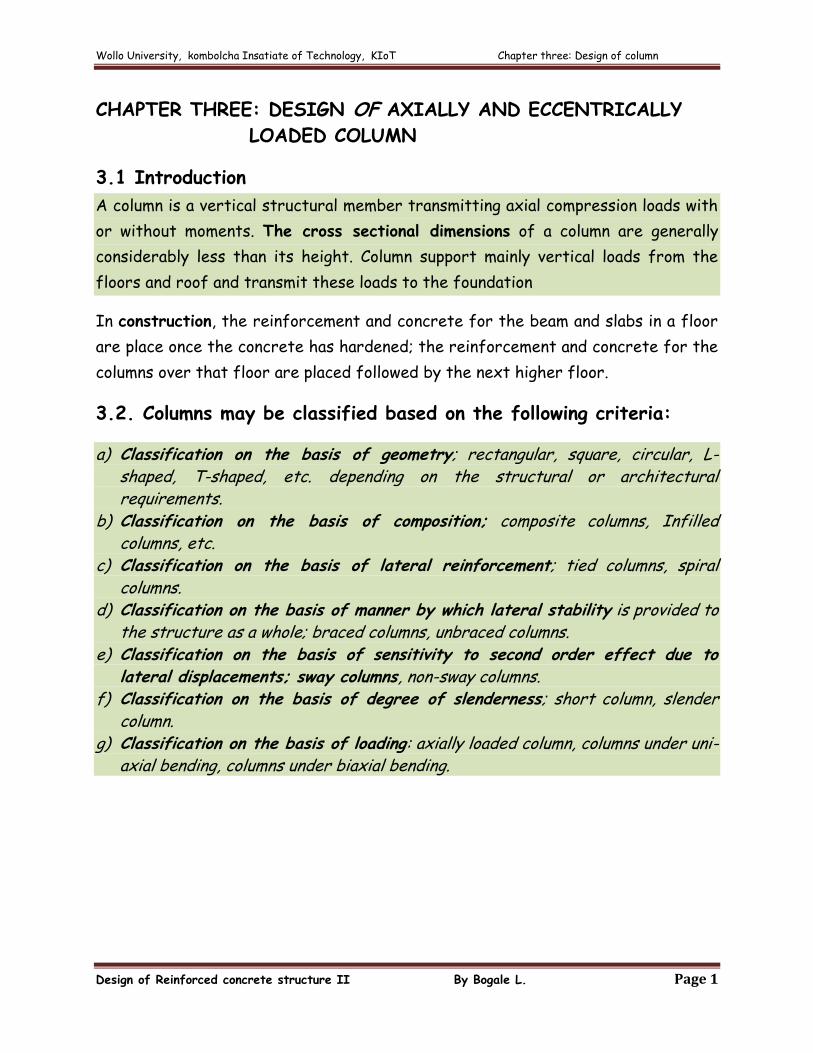
1) Classification on the basis of composition:
Composite/Infilled Columns
a) Composite columns: columns in which steel structural members are encased
in a concrete. Main reinforcement bars positioned with ties or spirals are
placed around the structural member
b) Infilled columns: columns having steel pipes filled with plain concrete or
lightly reinforced concrete.
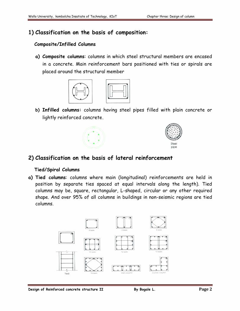
2) Classification on the basis of lateral reinforcement
Tied/Spiral Columns
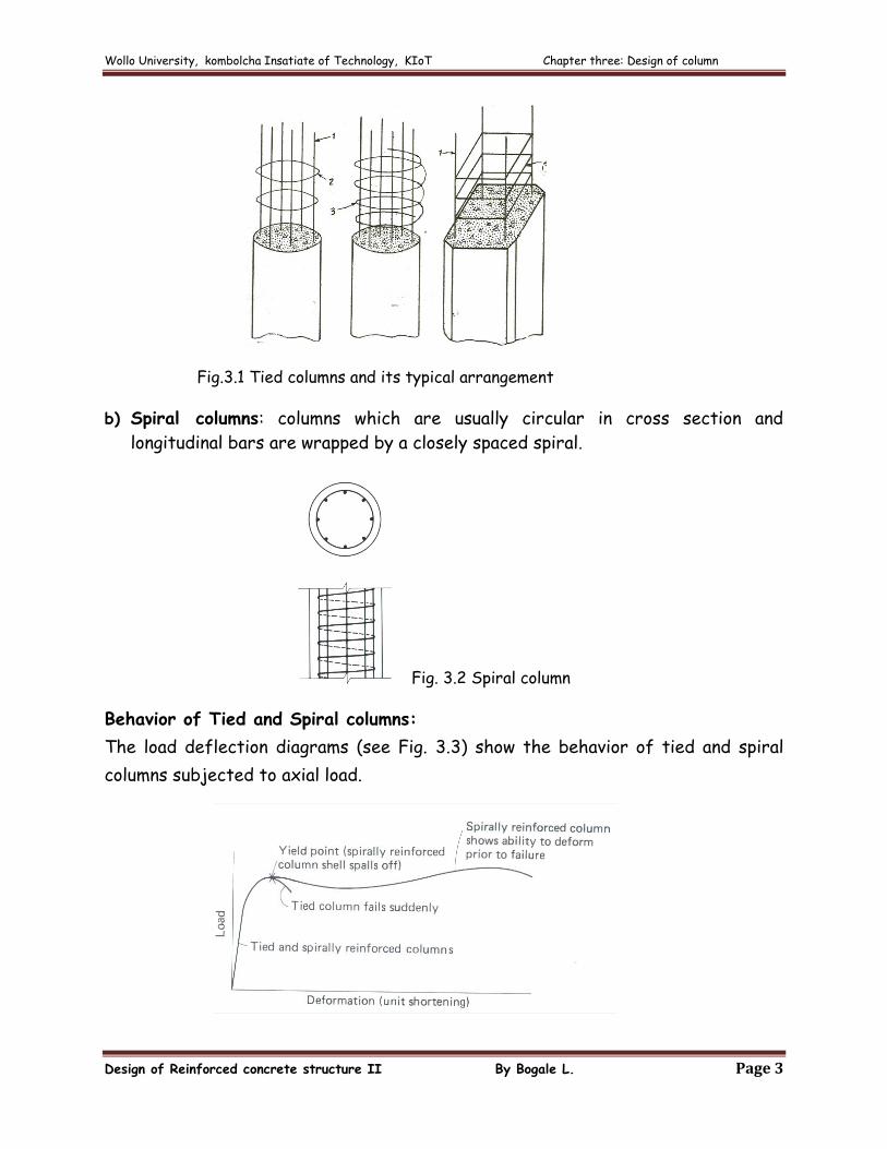
a) Tied columns: columns where main (longitudinal) reinforcements are held in
position by separate ties spaced at equal intervals along the length). Tied
columns may be, square, rectangular, L-shaped, circular or any other required
shape. And over 95% of all columns in buildings in non-seismic regions are tied
columns.
Wollo University, kombolcha Insatiate of Technology, KIoT Chapter three: Design of column
Design of Reinforced concrete structure II By Bogale L. Page 3
Fig.3.1 Tied columns and its typical arrangement
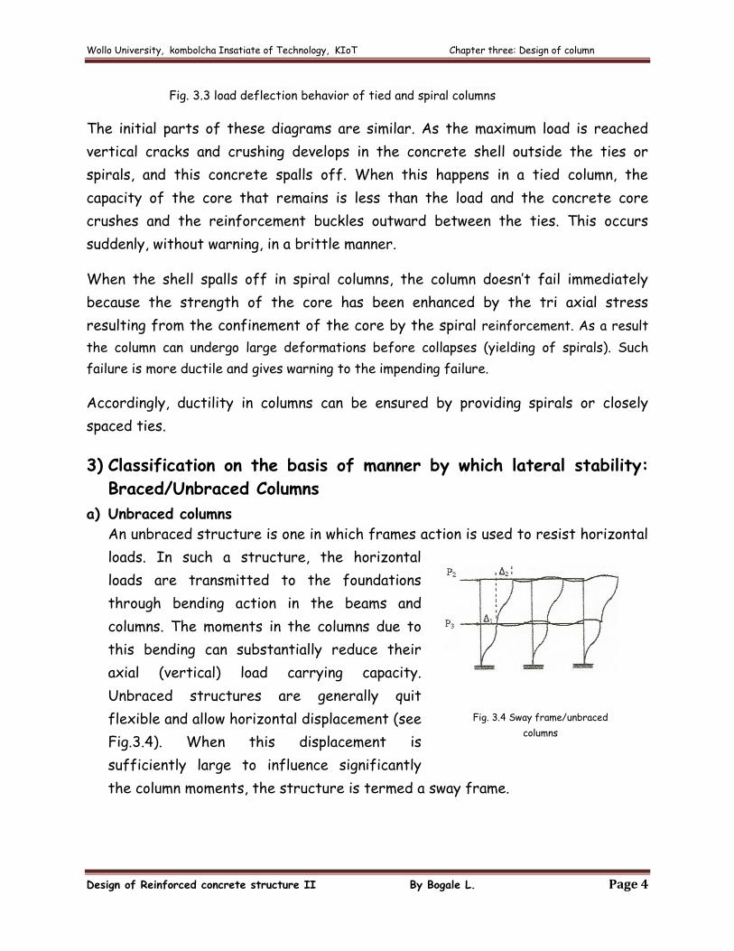
b) Spiral columns: columns which are usually circular in cross section and
longitudinal bars are wrapped by a closely spaced spiral.
Fig. 3.2 Spiral column
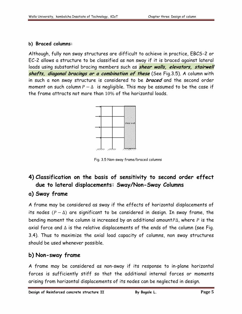
Behavior of Tied and Spiral columns:
The load deflection diagrams (see Fig. 3.3) show the behavior of tied and spiral
columns subjected to axial load.
Wollo University, kombolcha Insatiate of Technology, KIoT Chapter three: Design of column
Design of Reinforced concrete structure II By Bogale L. Page 4
Fig. 3.3 load deflection behavior of tied and spiral columns
The initial parts of these diagrams are similar. As the maximum load is reached
vertical cracks and crushing develops in the concrete shell outside the ties or
spirals, and this concrete spalls off. When this happens in a tied column, the
capacity of the core that remains is less than the load and the concrete core
crushes and the reinforcement buckles outward between the ties. This occurs
suddenly, without warning, in a brittle manner.
When the shell spalls off in spiral columns, the column doesn’t fail immediately
because the strength of the core has been enhanced by the tri axial stress
resulting from the confinement of the core by the spiral reinforcement. As a result
the column can undergo large deformations before collapses (yielding of spirals). Such
failure is more ductile and gives warning to the impending failure.
Accordingly, ductility in columns can be ensured by providing spirals or closely
spaced ties.
3) Classification on the basis of manner by which lateral stability:
Braced/Unbraced Columns
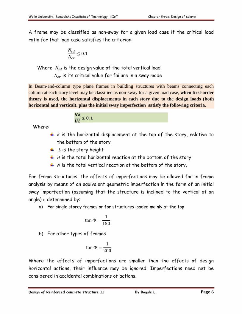
a) Unbraced columns
An unbraced structure is one in which frames action is used to resist horizontal
loads. In such a structure, the horizontal
loads are transmitted to the foundations
through bending action in the beams and
columns. The moments in the columns due to
this bending can substantially reduce their
axial (vertical) load carrying capacity.
Unbraced structures are generally quit
flexible and allow horizontal displacement (see
Fig.3.4). When this displacement is
sufficiently large to influence significantly
the column moments, the structure is termed a sway frame.
Fig. 3.4 Sway frame/unbraced
columns
Wollo University, kombolcha Insatiate of Technology, KIoT Chapter three: Design of column
Design of Reinforced concrete structure II By Bogale L. Page 5
b) Braced columns:
Although, fully non sway structures are difficult to achieve in practice, EBCS-2 or
EC-2 allows a structure to be classified as non sway if it is braced against lateral
loads using substantial bracing members such as shear walls, elevators, stairwell shafts, diagonal bracings or a combination of these (See Fig.3.5). A column with
in such a non sway structure is considered to be braced and the second order
moment on such column is negligible. This may be assumed to be the case if
the frame attracts not more than of the horizontal loads.
4) Classification on the basis of sensitivity to second order effect
due to lateral displacements: Sway/Non-Sway Columns
a) Sway frame
A frame may be considered as sway if the effects of horizontal displacements of
its nodes are significant to be considered in design. In sway frame, the
bending moment the column is increased by an additional amount , where is the
axial force and is the relative displacements of the ends of the column (see Fig.
3.4). Thus to maximize the axial load capacity of columns, non sway structures
should be used whenever possible.
b) Non-sway frame
A frame may be considered as non-sway if its response to in-plane horizontal
forces is sufficiently stiff so that the additional internal forces or moments
arising from horizontal displacements of its nodes can be neglected in design.
shear w all
Fig. 3.5 Non-sway frame/braced columns
Fig. 2.5 Non-sway frame/braced columns
Wollo University, kombolcha Insatiate of Technology, KIoT Chapter three: Design of column
Design of Reinforced concrete structure II By Bogale L. Page 6
A frame may be classified as non-sway for a given load case if the critical load
ratio for that load case satisfies the criterion:
Where: is the design value of the total vertical load
is its critical value for failure in a sway mode
In Beam-and-column type plane frames in building structures with beams connecting each
column at each story level may be classified as non-sway for a given load case, when first-order
theory is used, the horizontal displacements in each story due to the design loads (both
horizontal and vertical), plus the initial sway imperfection satisfy the following criteria.
Where:
is the horizontal displacement at the top of the story, relative to
the bottom of the story
is the story height
is the total horizontal reaction at the bottom of the story
is the total vertical reaction at the bottom of the story,
For frame structures, the effects of imperfections may be allowed for in frame
analysis by means of an equivalent geometric imperfection in the form of an initial
sway imperfection (assuming that the structure is inclined to the vertical at an
angle) determined by:
a) For single storey frames or for structures loaded mainly at the top
b) For other types of frames
Where the effects of imperfections are smaller than the effects of design
horizontal actions, their influence may be ignored. Imperfections need net be
considered in accidental combinations of actions.
Wollo University, kombolcha Insatiate of Technology, KIoT Chapter three: Design of column
Design of Reinforced concrete structure II By Bogale L. Page 7
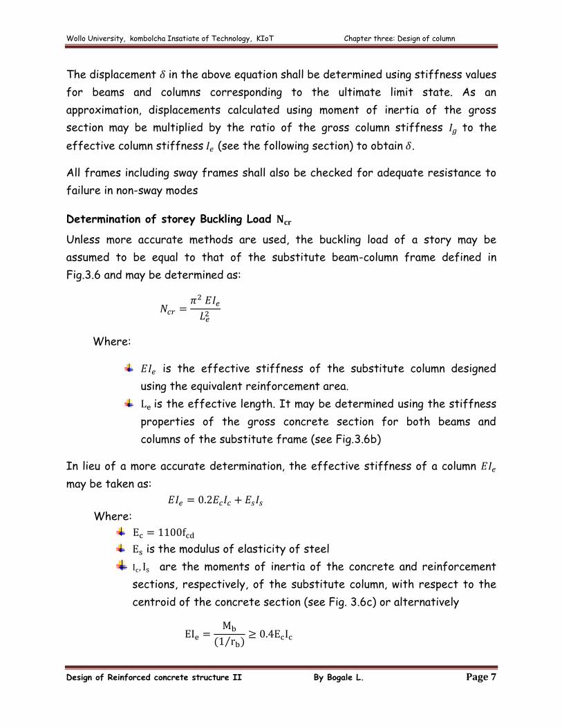
The displacement in the above equation shall be determined using stiffness values
for beams and columns corresponding to the ultimate limit state. As an
approximation, displacements calculated using moment of inertia of the gross
section may be multiplied by the ratio of the gross column stiffness to the
effective column stiffness (see the following section) to obtain .
All frames including sway frames shall also be checked for adequate resistance to
failure in non-sway modes
Determination of storey Buckling Load
Unless more accurate methods are used, the buckling load of a story may be
assumed to be equal to that of the substitute beam-column frame defined in
Fig.3.6 and may be determined as:
Where:
is the effective stiffness of the substitute column designed
using the equivalent reinforcement area.
is the effective length. It may be determined using the stiffness
properties of the gross concrete section for both beams and
columns of the substitute frame (see Fig.3.6b)
In lieu of a more accurate determination, the effective stiffness of a column
may be taken as:
Where:
is the modulus of elasticity of steel
are the moments of inertia of the concrete and reinforcement
sections, respectively, of the substitute column, with respect to the
centroid of the concrete section (see Fig. 3.6c) or alternatively
Wollo University, kombolcha Insatiate of Technology, KIoT Chapter three: Design of column
Design of Reinforced concrete structure II By Bogale L. Page 8
Where: is the balanced moment capacity of the substitute column,
is the curvature at balanced load and may be taken as
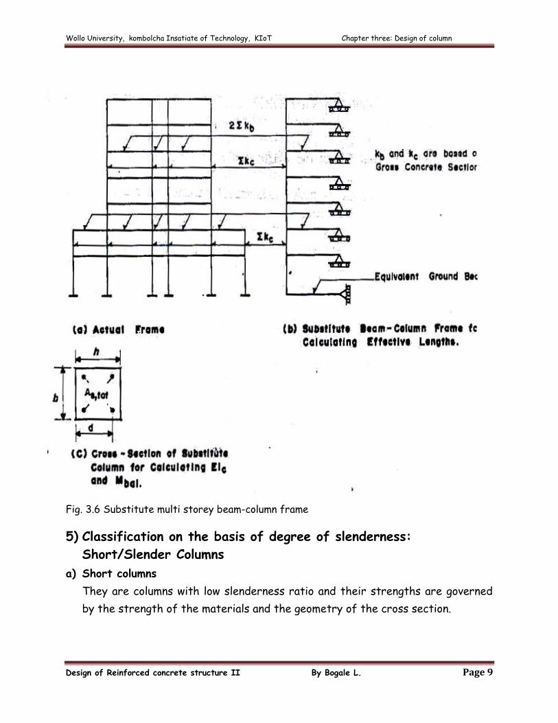
The equivalent reinforcement areas, in the substitute column to be used for
calculating and may be obtained by designing the substitute column at each
floor level to carry the story design axial load and amplified sway moment at the
critical section. The equivalent column dimensions of the substitute column may be
taken as shown in Fig, 2.6c below, in the case of rectangular columns. Circular
columns may be replaced by square columns of the same cross-sectional area. In
the above, concrete cover and bar arrangement in the substitute columns shall be
taken to be the same as those of the actual columns.
The amplified sway moment, to be used for the design of the substitute column,
may be found iteratively taking the first-order design moment in the substitute
column as an initial value.
In lieu of more accurate determination, the first-order design moment, , at the
critical section of the substitute column may be determined using:
Where and are defined before and shall not exceed .
Wollo University, kombolcha Insatiate of Technology, KIoT Chapter three: Design of column
Design of Reinforced concrete structure II By Bogale L. Page 9
Fig. 3.6 Substitute multi storey beam-column frame
5) Classification on the basis of degree of slenderness:
Short/Slender Columns
a) Short columns
They are columns with low slenderness ratio and their strengths are governed
by the strength of the materials and the geometry of the cross section.
Wollo University, kombolcha Insatiate of Technology, KIoT Chapter three: Design of column
Design of Reinforced concrete structure II By Bogale L. Page 10
b) Slender columns
They are columns with high slenderness ratio and their strength may be
significantly reduced by lateral deflection.
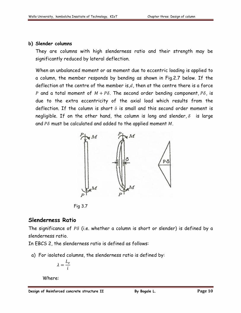
When an unbalanced moment or as moment due to eccentric loading is applied to
a column, the member responds by bending as shown in Fig.2.7 below. If the
deflection at the centre of the member is, , then at the centre there is a force
and a total moment of . The second order bending component, , is
due to the extra eccentricity of the axial load which results from the
deflection. If the column is short is small and this second order moment is
negligible. If on the other hand, the column is long and slender, is large
and must be calculated and added to the applied moment .
Fig 3.7
Slenderness Ratio
The significance of (i.e. whether a column is short or slender) is defined by a
slenderness ratio.
In EBCS 2, the slenderness ratio is defined as follows:
a) For isolated columns, the slenderness ratio is defined by:
Where:
Wollo University, kombolcha Insatiate of Technology, KIoT Chapter three: Design of column
Design of Reinforced concrete structure II By Bogale L. Page 11
is the effective buckling length
is the minimum radius of gyration. The radius of gyration is equal
to
Where: is the second moment of area of the section
is cross sectional area
b) For multistory sway frames comprising rectangular sub frames, the following
expression may be used to calculate the slenderness ratio of the columns in
the same story.
Where: is the sum of the cross-sectional areas of all the columns of the
story
is the total lateral stiffness of the columns of the story (story
rigidity), with modulus of elasticity taken as unity
is the story height
Limits of Slenderness
The slenderness ratio of concrete columns shall not exceed 140
Second order moment in a column can be ignored if
a) For sway frames, the greater of
Where
b) For non-sway frames
Wollo University, kombolcha Insatiate of Technology, KIoT Chapter three: Design of column
Design of Reinforced concrete structure II By Bogale L. Page 12
Where and are the first-order (calculated) moments at the ends, being
always positive and greater in magnitude than , and being positive if member is
bent in single curvature and negative if bent in double curvature
Wollo University, kombolcha Insatiate of Technology, KIoT Chapter three: Design of column
Design of Reinforced concrete structure II By Bogale L. Page 13
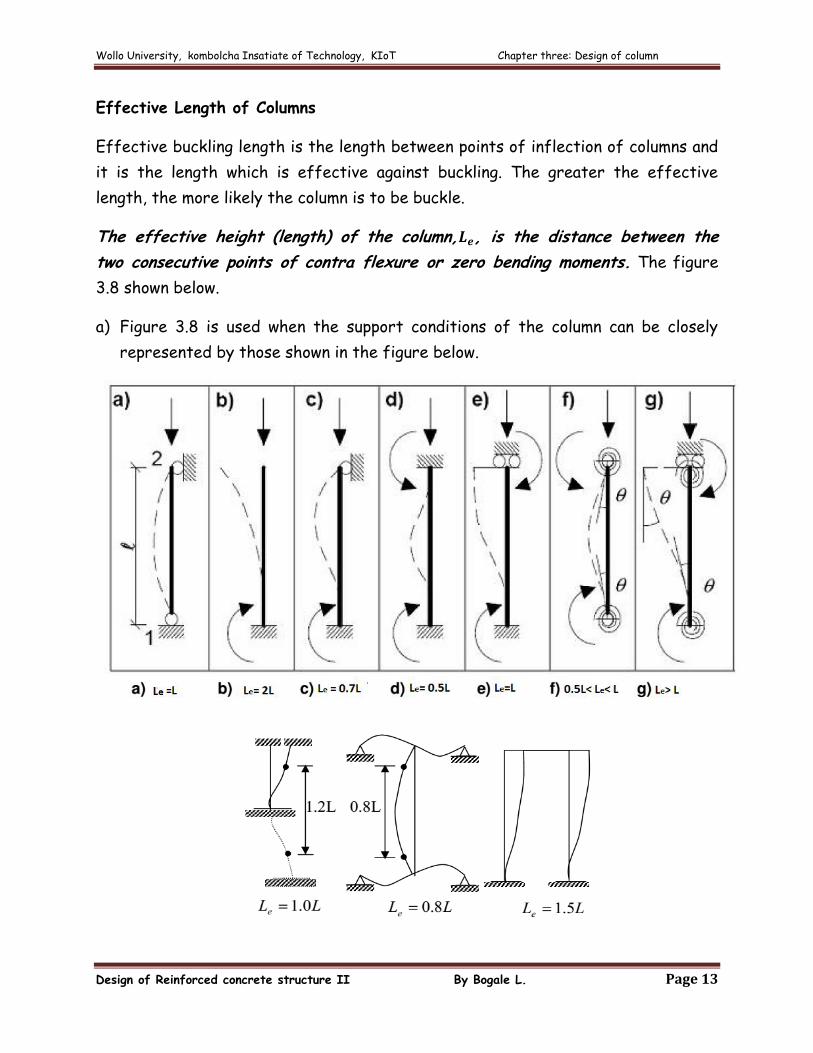
Effective Length of Columns
Effective buckling length is the length between points of inflection of columns and
it is the length which is effective against buckling. The greater the effective
length, the more likely the column is to be buckle.
The effective height (length) of the column, , is the distance between the
two consecutive points of contra flexure or zero bending moments. The figure
3.8 shown below.
a) Figure 3.8 is used when the support conditions of the column can be closely
represented by those shown in the figure below.
Wollo University, kombolcha Insatiate of Technology, KIoT Chapter three: Design of column
Design of Reinforced concrete structure II By Bogale L. Page 14
Fig 3.8: Examples of different buckling modes and corresponding effective length for
isolated members
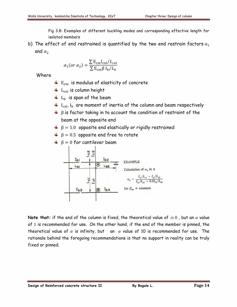
b) The effect of end restrained is quantified by the two end restrain factors
and
Where
is modulus of elasticity of concrete
is column height
is span of the beam
, are moment of inertia of the column and beam respectively
is factor taking in to account the condition of restraint of the
beam at the opposite end
opposite end elastically or rigidly restrained
opposite end free to rotate
for cantilever beam
Note that: if the end of the column is fixed, the theoretical value of , but an value
of is recommended for use. On the other hand, if the end of the member is pinned, the
theoretical value of is infinity, but an value of 10 is recommended for use. The
rationale behind the foregoing recommendations is that no support in reality can be truly
fixed or pinned.
Wollo University, kombolcha Insatiate of Technology, KIoT Chapter three: Design of column
Design of Reinforced concrete structure II By Bogale L. Page 15
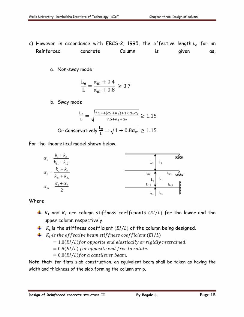
c) However in accordance with EBCS-2, 1995, the effective length for an
Reinforced concrete Column is given as,
a. Non-sway mode
b. Sway mode
Or Conservatively
For the theoretical model shown below.
2
21
2221
22
1211
11
m
c
c
kk
kk
kk
kk
Where
and are column stiffness coefficients for the lower and the
upper column respectively.
is the stiffness coefficient of the column being designed.
Note that: for flats slab construction, an equivalent beam shall be taken as having the
width and thickness of the slab forming the column strip.
Lc2
Lc
Lc1
Ib11 Ib12
Ib22 Ib21
Ic
Ic1
Ic2
Wollo University, kombolcha Insatiate of Technology, KIoT Chapter three: Design of column
Design of Reinforced concrete structure II By Bogale L. Page 16
3.3. Reinforcement arrangement and minimum requirement
Main or Longitudinal Reinforcement:
The area of longitudinal reinforcement shall neither be less than nor
more than . The upper limit shall be observed even where bars overlap.
(Area of longitudinal reinforcement,
)
For columns with a larger cross-section than required by considerations of
loading, a reduced effective area not less than one-half die total area may be
used to determine minimum reinforcement and design strength
The minimum number of longitudinal reinforcing bars shall be 6 for bars in a
circular arrangement and 4 for bars in a rectangular arrangement
The diameter of longitudinal bars shall not be less than 12 mm ,
The minimum lateral dimension of a column shall be at least 150 mm and
The minimum diameter of a spiral column is 200mm.
The Minimum cover to reinforcement should never be less than
(a)
(b)
Where
is the diameter of bar
is the equivalent diameter for a bundle
the largest nominal maximum aggregate size.
A minimum concrete cover shall be provided in order to ensure:
The safe transmission of bond forces
That spalling will not occur
An adequate fire resistance
The protection of the steel against corrosion
Functions of Lateral Reinforcement
They hold the longitudinal bars in position in the forms while the concrete is
being placed
Wollo University, kombolcha Insatiate of Technology, KIoT Chapter three: Design of column
Design of Reinforced concrete structure II By Bogale L. Page 17
They prevent the slender longitudinal bars from buckling out ward by
bursting the thin concrete cover.
Rules for the arrangement:
a) The diameter of ties or spirals shall not be less than 6 mm or one quarter
of the diameter of the longitudinal bars. or
b) The center-to-center spacing of lateral reinforcement shall not exceed:
Where:
the minimum diameter of longitudinal bars.
is ties or spirals diameter / lateral reinforcement
is least dimension of column
300 mm
c) Pitch of spiral
d) Ties shall be arranged such that every bar or group of bars placed in a
corner and alternate longitudinal bar shall have lateral support provided by
the corner of a tie with an included angle of not more than 1350 and no bar
shall be further than 150 mm clear on each side along the tie from such a
laterally supported bar (see Fig.3.10)
e) Up to five longitudinal bars in each corner may be secured against lateral
buckling by means of the main ties. The center-to-center distance between
the outermost of these bars and the corner bar shall not exceed 15 times
the diameter of the tie (see Fig.3.10)
f) Spirals or circular ties may be used for longitudinal bars located around the
perimeter of a circle. The pitch of spirals shall not exceed 100 mm.
Wollo University, kombolcha Insatiate of Technology, KIoT Chapter three: Design of column
Design of Reinforced concrete structure II By Bogale L. Page 18
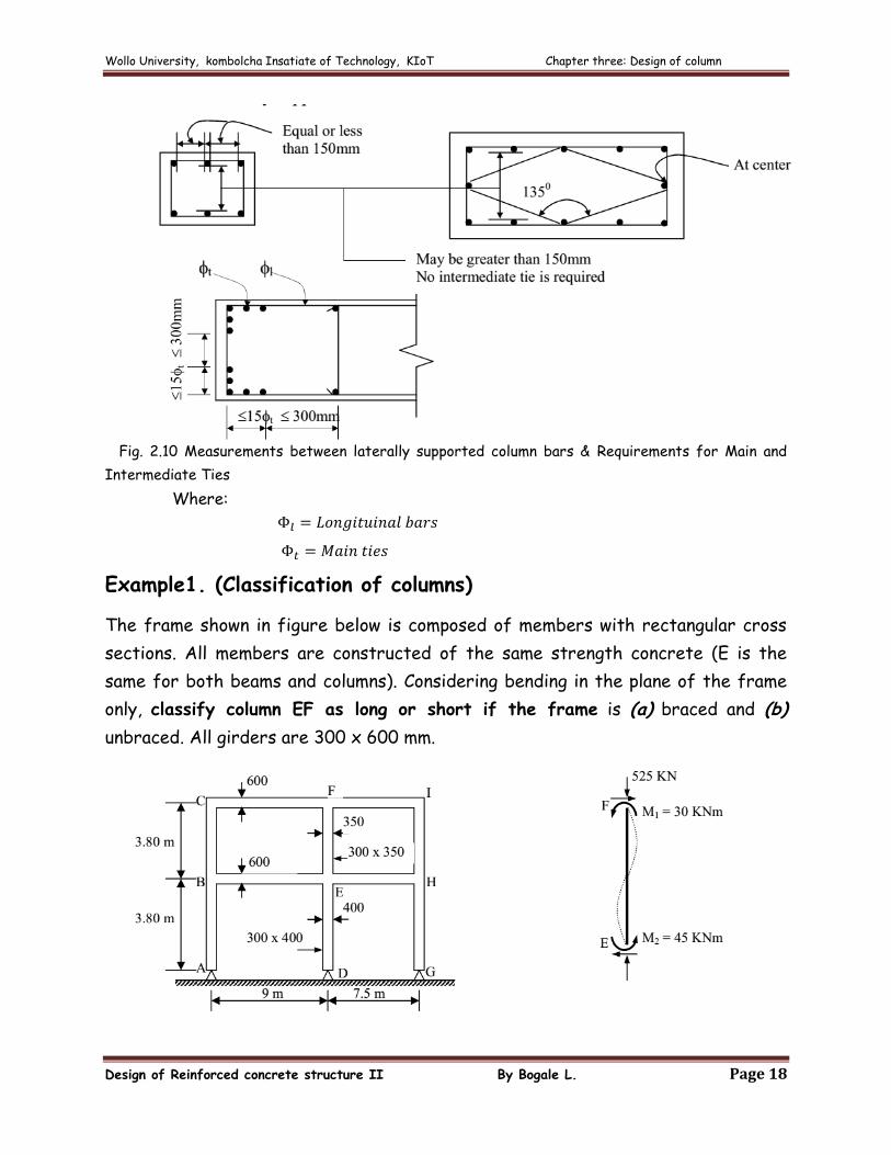
Fig. 2.10 Measurements between laterally supported column bars & Requirements for Main and
Intermediate Ties
Where:
Example1. (Classification of columns)
The frame shown in figure below is composed of members with rectangular cross
sections. All members are constructed of the same strength concrete (E is the
same for both beams and columns). Considering bending in the plane of the frame
only, classify column EF as long or short if the frame is (a) braced and (b)
unbraced. All girders are 300 x 600 mm.
Wollo University, kombolcha Insatiate of Technology, KIoT Chapter three: Design of column
Design of Reinforced concrete structure II By Bogale L. Page 19
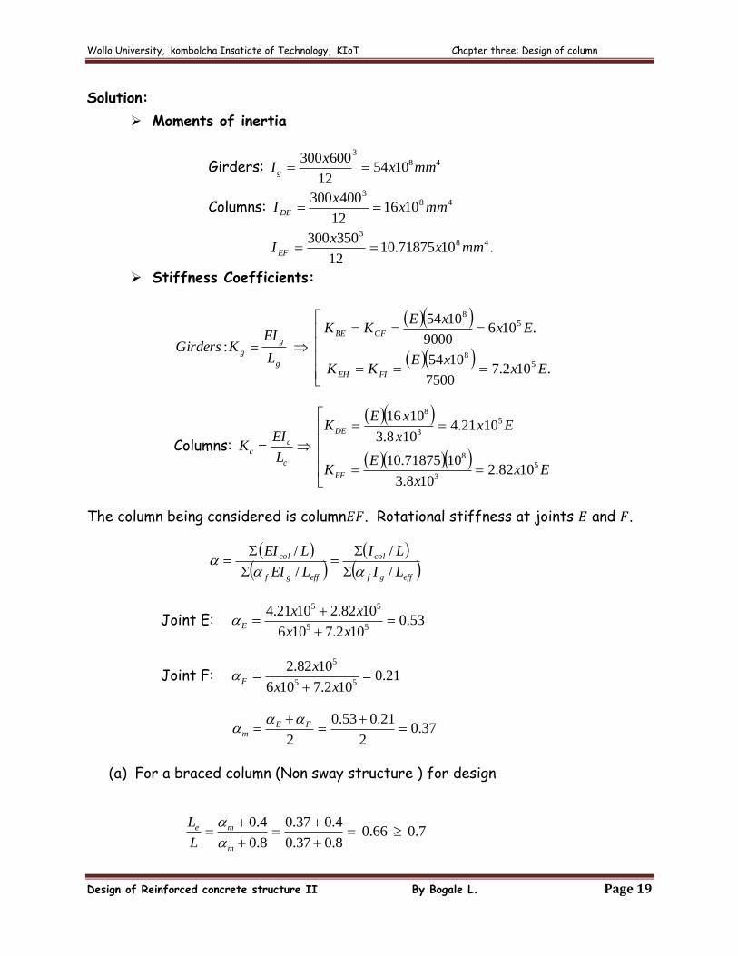
Solution:
Moments of inertia
Girders: 48
3
105412
600300mmx
xIg
Columns: 483
101612
400300mmx
xI DE
.1071875.1012
350300 483
mmxx
I EF
Stiffness Coefficients:
.102.77500
1054
.1069000
1054
:5
8
58
ExxE
KK
ExxE
KK
L
EIKGirders
FIEH
CFBE
g
g
g
Columns:
Exx
EK
Exx
xEK
L
EIK
EF
DE
c
cc
5
3
8
5
3
8
1082.2108.3
1071875.10
1021.4108.3
1016
The column being considered is column . Rotational stiffness at joints and .
effgf
col
effgf
col
LI
LI
LEI
LEI
/
/
/
/
Joint E: 53.0102.7106
1082.21021.455
55
xx
xxE
Joint F: 21.0102.7106
1082.255
5
xx
xF
37.02
21.053.0
2
FE
m
(a) For a braced column (Non sway structure ) for design
7.066.08.037.0
4.037.0
8.0
4.0
m
me
L
L
Wollo University, kombolcha Insatiate of Technology, KIoT Chapter three: Design of column
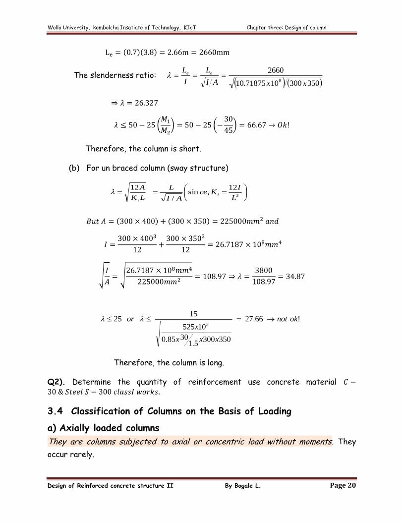
Design of Reinforced concrete structure II By Bogale L. Page 20
The slenderness ratio: 3503001071875.10
2660
8 xxAI
L
I
L ee
Therefore, the column is short.
(b) For un braced column (sway structure)
3
12,sin
/
12
L
IKce
AI
L
LK
Ai
i
!66.27
3503005.1
3085.0
10525
1525
3oknot
xxx
xor
Therefore, the column is long.
Q2). Determine the quantity of reinforcement use concrete material
3.4 Classification of Columns on the Basis of Loading
a) Axially loaded columns
They are columns subjected to axial or concentric load without moments. They
occur rarely.
Wollo University, kombolcha Insatiate of Technology, KIoT Chapter three: Design of column
Design of Reinforced concrete structure II By Bogale L. Page 21
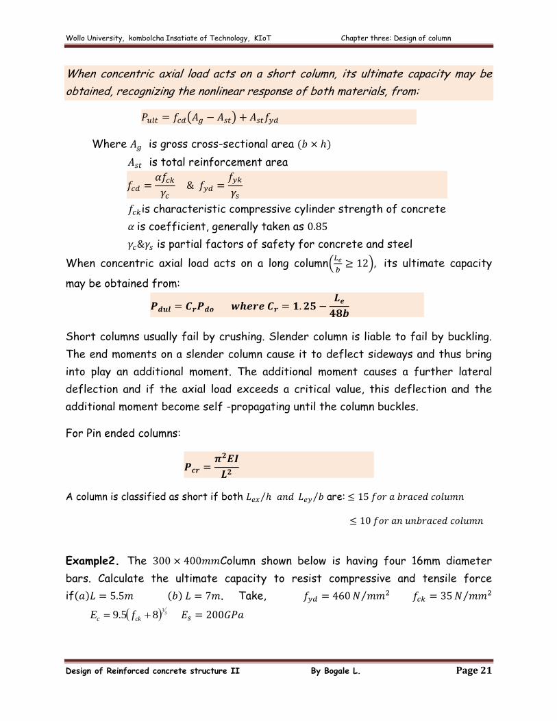
When concentric axial load acts on a short column, its ultimate capacity may be
obtained, recognizing the nonlinear response of both materials, from:
Where is gross cross-sectional area
is total reinforcement area
is characteristic compressive cylinder strength of concrete
is coefficient, generally taken as
is partial factors of safety for concrete and steel
When concentric axial load acts on a long column
its ultimate capacity
may be obtained from:
Short columns usually fail by crushing. Slender column is liable to fail by buckling.
The end moments on a slender column cause it to deflect sideways and thus bring
into play an additional moment. The additional moment causes a further lateral
deflection and if the axial load exceeds a critical value, this deflection and the
additional moment become self -propagating until the column buckles.
For Pin ended columns:
A column is classified as short if both are:
Example2. The Column shown below is having four 16mm diameter
bars. Calculate the ultimate capacity to resist compressive and tensile force
if . Take,
31
85.9 ckc fE
Wollo University, kombolcha Insatiate of Technology, KIoT Chapter three: Design of column
Design of Reinforced concrete structure II By Bogale L. Page 22
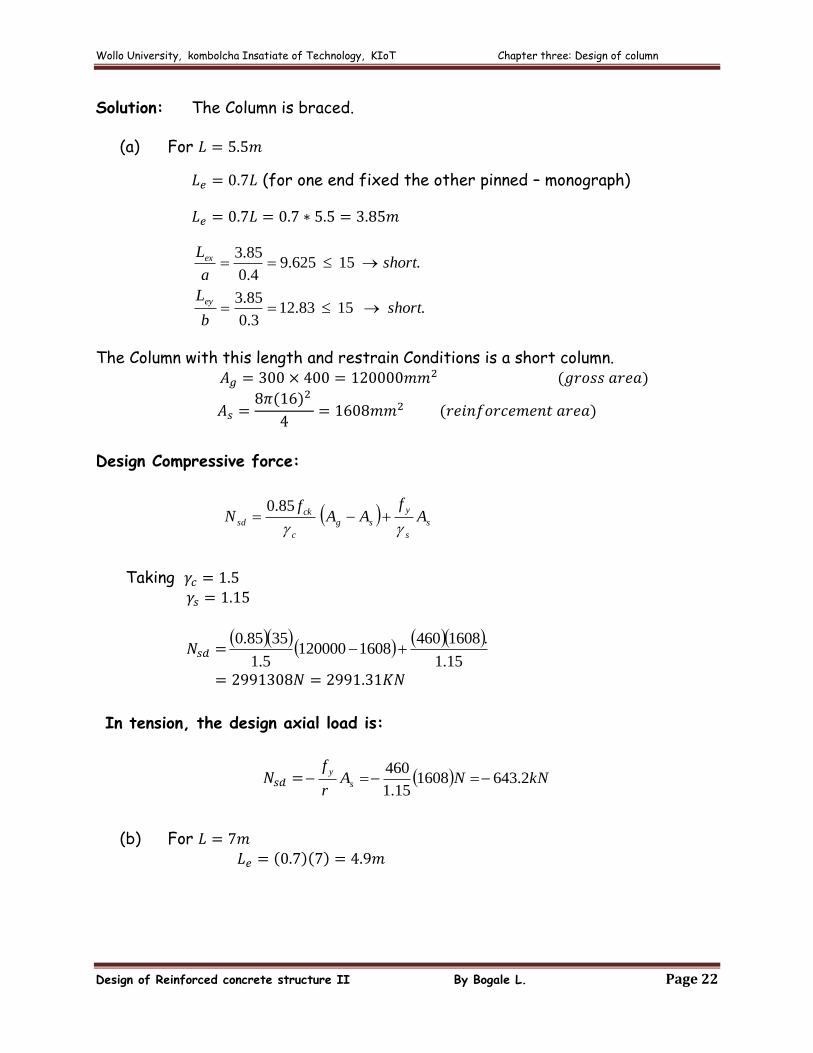
Solution: The Column is braced.
(a) For
(for one end fixed the other pinned – monograph)
.1583.123.0
85.3
.15625.94.0
85.3
shortb
L
shorta
L
ey
ex
The Column with this length and restrain Conditions is a short column.
Design Compressive force:
s
s
y
sg
c
ck
sd Af
AAf
N
85.0
Taking
15.1
.16084601608120000
5.1
3585.0
In tension, the design axial load is:
kNNAr
fs
y2.6431608
15.1
460
(b) For
Wollo University, kombolcha Insatiate of Technology, KIoT Chapter three: Design of column
Design of Reinforced concrete structure II By Bogale L. Page 23
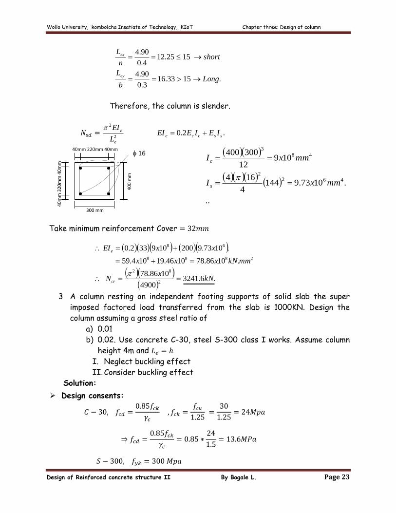
.1533.163.0
90.4
1525.124.0
90.4
Longb
L
shortn
L
ey
ex
Therefore, the column is slender.
.2.02
2
sscce
e
e IEIEEIL
EI
..
.1073.91444
164
10912
300400
4622
48
3
mmxI
mmxI
s
c
Take minimum reinforcement Cover
.6.32414900
1086.78
.1086.781046.19104.59
.1073.9200109332.0
2
82
2888
68
kNx
N
mmkNxxx
xxEI
cr
e
3 A column resting on independent footing supports of solid slab the super
imposed factored load transferred from the slab is 1000KN. Design the
column assuming a gross steel ratio of
a) 0.01
b) 0.02. Use concrete C-30, steel S-300 class I works. Assume column
height 4m and
I. Neglect buckling effect
II. Consider buckling effect Solution:
Design consents:
40
0 m
m
300 mm
40
mm
32
0mm
40m
m
40mm 220mm 40mm 16
Wollo University, kombolcha Insatiate of Technology, KIoT Chapter three: Design of column
Design of Reinforced concrete structure II By Bogale L. Page 24
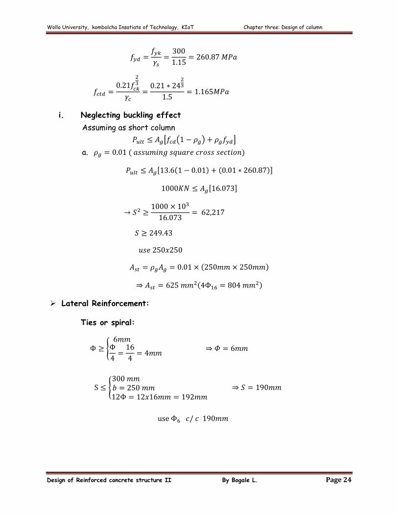
i. Neglecting buckling effect
Assuming as short column
a.
Lateral Reinforcement:
Ties or spiral:
Wollo University, kombolcha Insatiate of Technology, KIoT Chapter three: Design of column
Design of Reinforced concrete structure II By Bogale L. Page 25
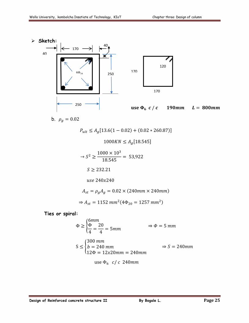
Sketch:
b.
Ties or spiral:
170 40
40
250
250 170
170
120
Wollo University, kombolcha Insatiate of Technology, KIoT Chapter three: Design of column
Design of Reinforced concrete structure II By Bogale L. Page 26
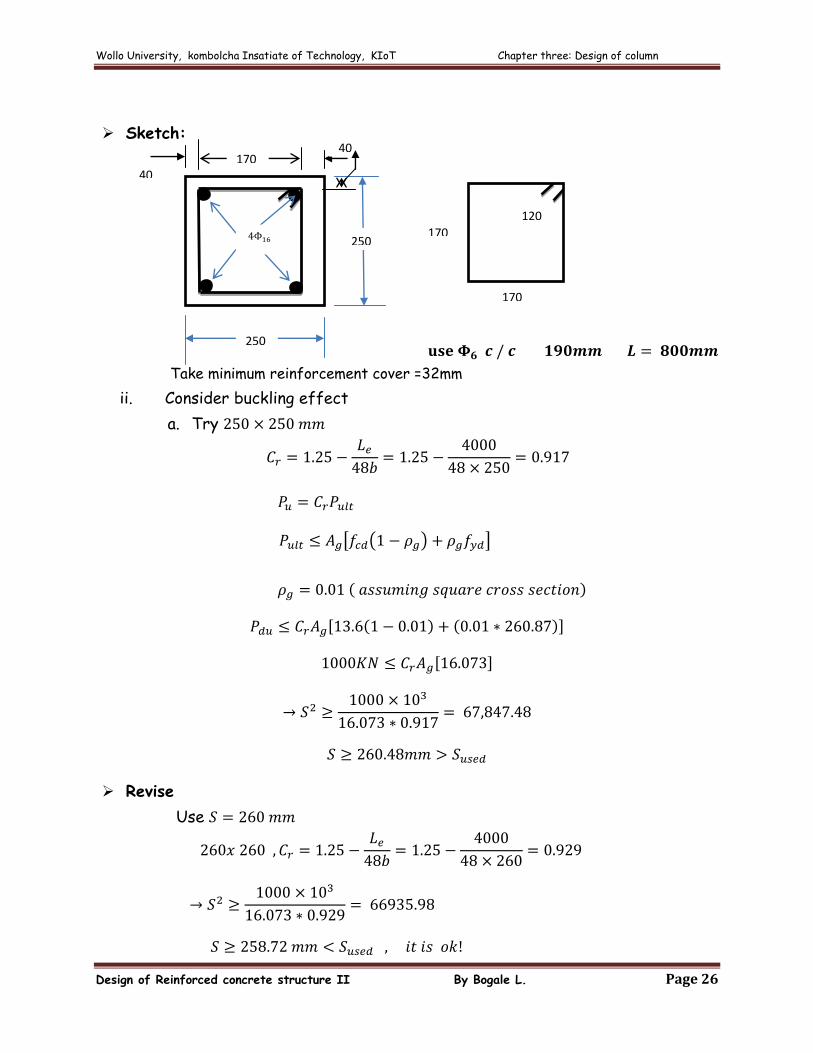
Sketch:
Take minimum reinforcement cover =32mm
ii. Consider buckling effect
a. Try
Revise
Use
170 40
40
250
250 170
170
120
Wollo University, kombolcha Insatiate of Technology, KIoT Chapter three: Design of column
Design of Reinforced concrete structure II By Bogale L. Page 27
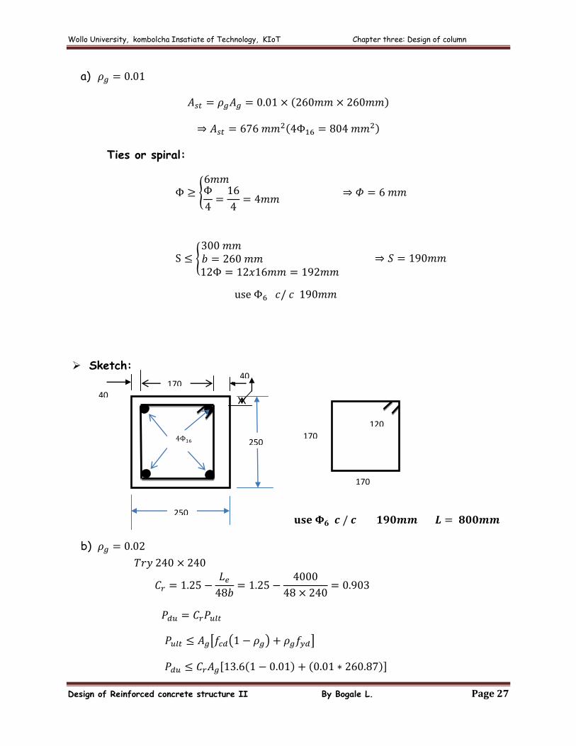
a)
Ties or spiral:
Sketch:
b)
170 40
40
250
250 170
170
120
Wollo University, kombolcha Insatiate of Technology, KIoT Chapter three: Design of column
Design of Reinforced concrete structure II By Bogale L. Page 28
Revise
Use
Ties or spiral:
Wollo University, kombolcha Insatiate of Technology, KIoT Chapter three: Design of column
Design of Reinforced concrete structure II By Bogale L. Page 29
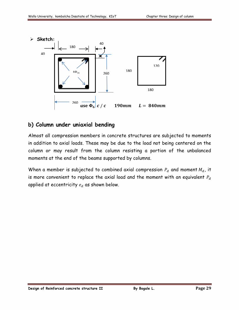
Sketch:
b) Column under uniaxial bending
Almost all compression members in concrete structures are subjected to moments
in addition to axial loads. These may be due to the load not being centered on the
column or may result from the column resisting a portion of the unbalanced
moments at the end of the beams supported by columns.
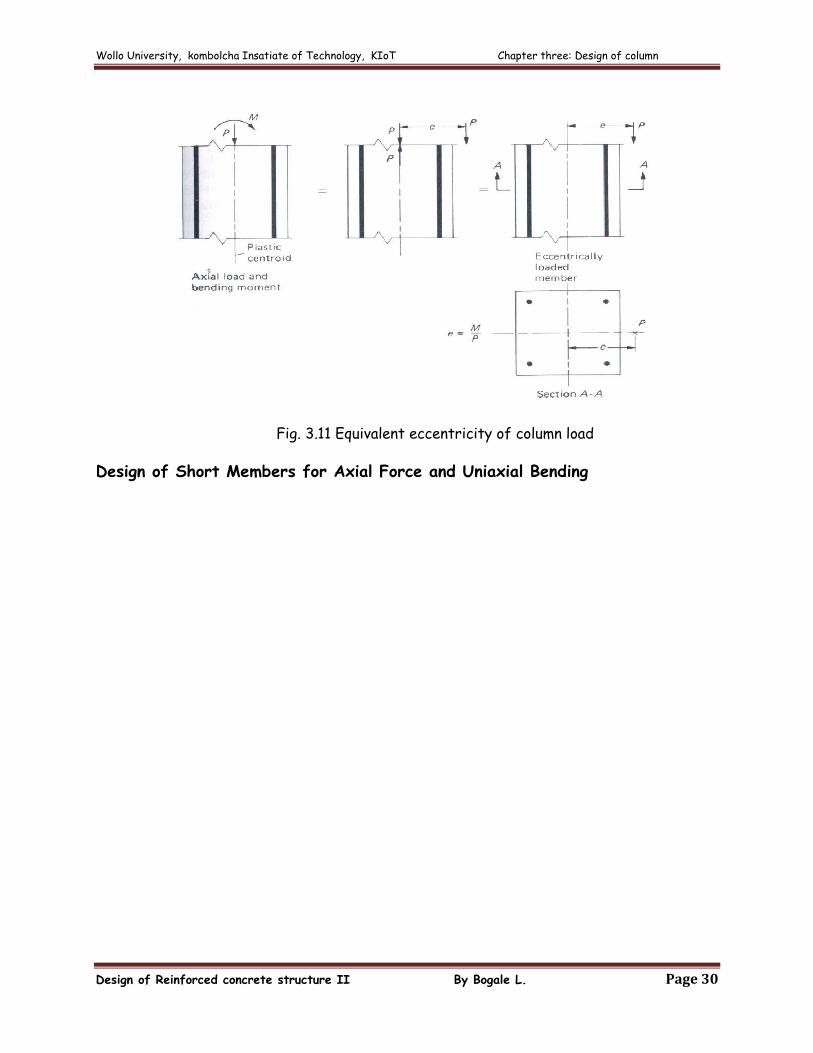
When a member is subjected to combined axial compression and moment , it
is more convenient to replace the axial load and the moment with an equivalent
applied at eccentricity as shown below.
180 40
40
260
260 180
180
120
Wollo University, kombolcha Insatiate of Technology, KIoT Chapter three: Design of column
Design of Reinforced concrete structure II By Bogale L. Page 30
Fig. 3.11 Equivalent eccentricity of column load
Design of Short Members for Axial Force and Uniaxial Bending
Wollo University, kombolcha Insatiate of Technology, KIoT Chapter three: Design of column
Design of Reinforced concrete structure II By Bogale L. Page 31
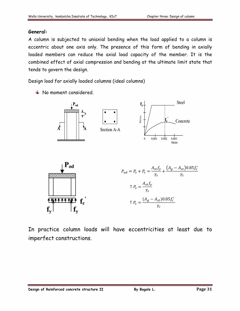
General:
A column is subjected to uniaxial bending when the load applied to a column is
eccentric about one axis only. The presence of this form of bending in axially
loaded members can reduce the axial load capacity of the member. It is the
combined effect of axial compression and bending at the ultimate limit state that
tends to govern the design.
Design load for axially loaded columns (ideal columns)
No moment considered.
In practice column loads will have eccentricities at least due to
imperfect constructions.
Wollo University, kombolcha Insatiate of Technology, KIoT Chapter three: Design of column
Design of Reinforced concrete structure II By Bogale L. Page 32
3.5. Design of columns, EBSC 2
I. General
The internal forces and moments may generally be determined by elastic global
analysis using either first order theory or second order theory.
a) First-order theory, using the initial geometry of the structure, may be used
in the following cases
Non-sway frames
Braced frames
Design methods which make indirect allowances for second-order
effects.
b) Second-order theory, taking into account the influence of the deformation
of the structure, may be used in all cases.
II. Design of Non sway Frames
Individual non-sway compression members shall be considered to be isolated
elements and be designed accordingly.
Design of Isolated Columns
For buildings, a design method may be used which assumes the compression
members to be isolated. The additional eccentricity induced in the column by its
deflection is then calculated as a function of slenderness ratio and curvature at
the critical section
Total eccentricity
1. The total eccentricity to be used for the design of columns of constant
cross-section at the critical section is given by:
Where: , is equivalent constant first-order eccentricity of the design axial
load
Wollo University, kombolcha Insatiate of Technology, KIoT Chapter three: Design of column
Design of Reinforced concrete structure II By Bogale L. Page 33
is the additional eccentricity allowance for imperfections. For
isolated columns:
mm 20300
e
a
Le
is the second-order eccentricity
First order equivalent eccentricity
1. For first-order eccentricity e0 is equal at both ends of a column
2. For first-order moments varying linearly along the length, the equivalent
eccentricity is the higher of the following two values:
Where:
and are the first-order eccentricities at the ends, e02 being
positive and greater in magnitude than e01.
is positive if the column bents in single curvature and negative if
the column bends in double curvature.
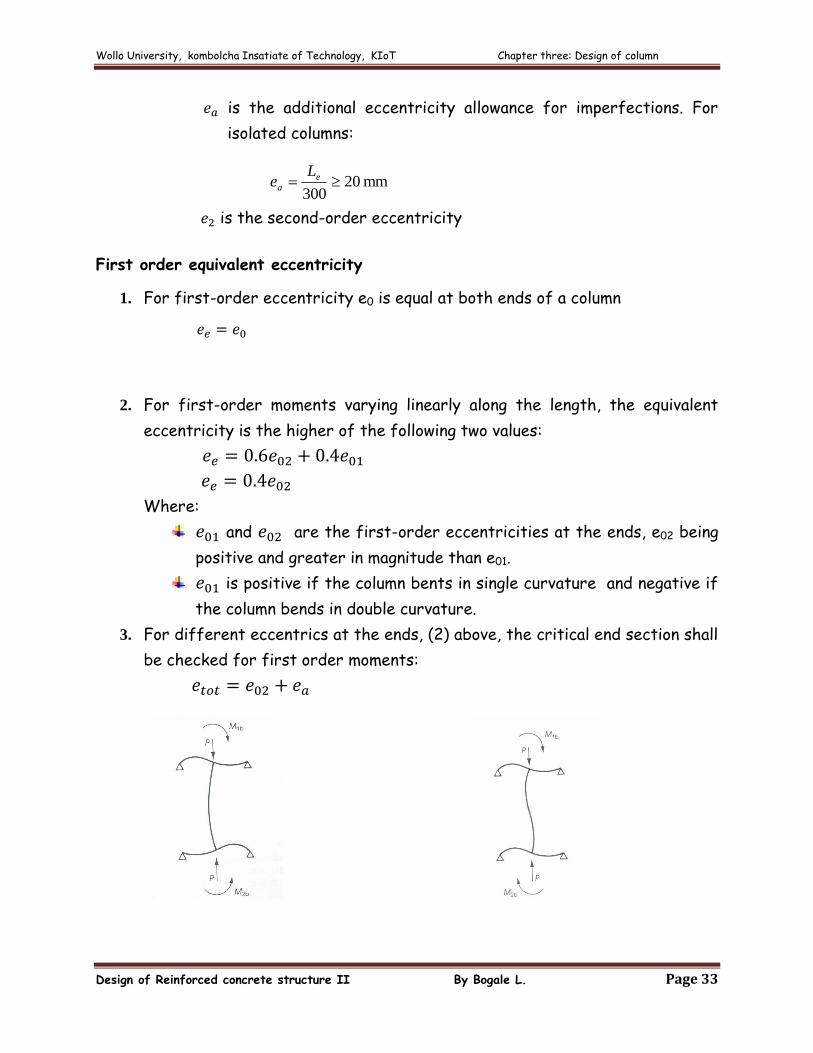
3. For different eccentrics at the ends, (2) above, the critical end section shall
be checked for first order moments:
Wollo University, kombolcha Insatiate of Technology, KIoT Chapter three: Design of column
Design of Reinforced concrete structure II By Bogale L. Page 34
Second order eccentricity
1. The second-order eccentricity e2 of an isolated column may be obtained as
Where Le is the effective buckling length of the column
is the curvature at the critical section.
2. The curvature is approximated by:
Where:
is the effective column dimension in the plane of buckling
is the design moment at the critical section including second-
order effects
is the balanced moment capacity of the column.
3. The appropriate value of may be found iteratively taking an initial value
corresponding to first-order actions.
III. Design of Sway Frames
The second order effects in the sway mode can be accounted using either of the
following two methods:
a) Second-order elastic global analysis: When this analysis is used, the
resulting forces and moment may directly be used for member design.
b) Amplified Sway Moments Method: In this method, the sway moments found
by a first-order analysis shall be increased by multiplying them by the
moment magnification factor:
Wollo University, kombolcha Insatiate of Technology, KIoT Chapter three: Design of column
Design of Reinforced concrete structure II By Bogale L. Page 35
Where is the design value of the total vertical load
is its critical value for failure in a sway mode.
The amplified sway moments method shall not be used when the critical load ratio
Sway moments are those associated with the horizontal translation of the top of
story relative to the bottom of that story. They arise from horizontal loading and
may also arise from vertical loading if either the structure or the loading is
asymmetrical.
As an alternative to determining
direct, the following approximation may be used in
beam and-column type frames
(see section 3.2)
Where , , and are as defined before.
In the presence of torsional eccentricity in any floor of a structure, unless more
accurate methods are used, the sway moments due to torsion should be increased
by multiplying them by the larger moment magnification factor , obtained for the
two orthogonal directions of the lateral loads acting on the structure.
3.6. Interaction diagram
The presence of bending in axially loaded members can reduce the axial load
capacity of the member
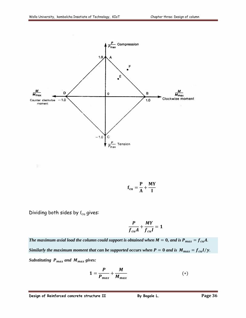
To illustrate conceptually the interaction between moment and axial load in a column, an
idealized homogenous and elastic column with a compressive strength, , equal to its tensile
strength , will be considered. For such a column failure would occurs in a compression
when the maximum stresses reached as given by:
Wollo University, kombolcha Insatiate of Technology, KIoT Chapter three: Design of column
Design of Reinforced concrete structure II By Bogale L. Page 36
Dividing both sides by gives:
The maximum axial load the column could support is obtained when , and is
Similarly the maximum moment that can be supported occurs when and is
Substituting and gives:

Wollo University, kombolcha Insatiate of Technology, KIoT Chapter three: Design of column
Design of Reinforced concrete structure II By Bogale L. Page 37
This is known as interaction equations because it shows the interaction of or
relationship between and at failure. It is plotted as line (see Fig.). A similar
equation for a tensile load, , governed by , gives line in the figure. The plot is
referred to as an interaction diagram.
Points on the lines represent combination of and corresponding to the
resistance of the section. A point inside the diagram such as represents a
combination of and that will not cause failure. Load combinations falling on
the line or outside the line, such as point will equal or exceed the resistance of
the section and hence will cause failure.
Interaction Diagrams for Reinforced concrete Columns
Since reinforced concrete is not elastic and has a tensile strength that is lower
than its compressive strength, the general shape of the diagram resembles Fig.
3.12
Fig. 3.12 Interaction diagram for column in combined bending and axial load
Balanced condition: For a given cross section the design axial force acts at one
specific eccentricity to cause failure by simultaneous yielding of tension steel
and crushing of concrete (see Fig. 3.12)
Wollo University, kombolcha Insatiate of Technology, KIoT Chapter three: Design of column
Design of Reinforced concrete structure II By Bogale L. Page 38
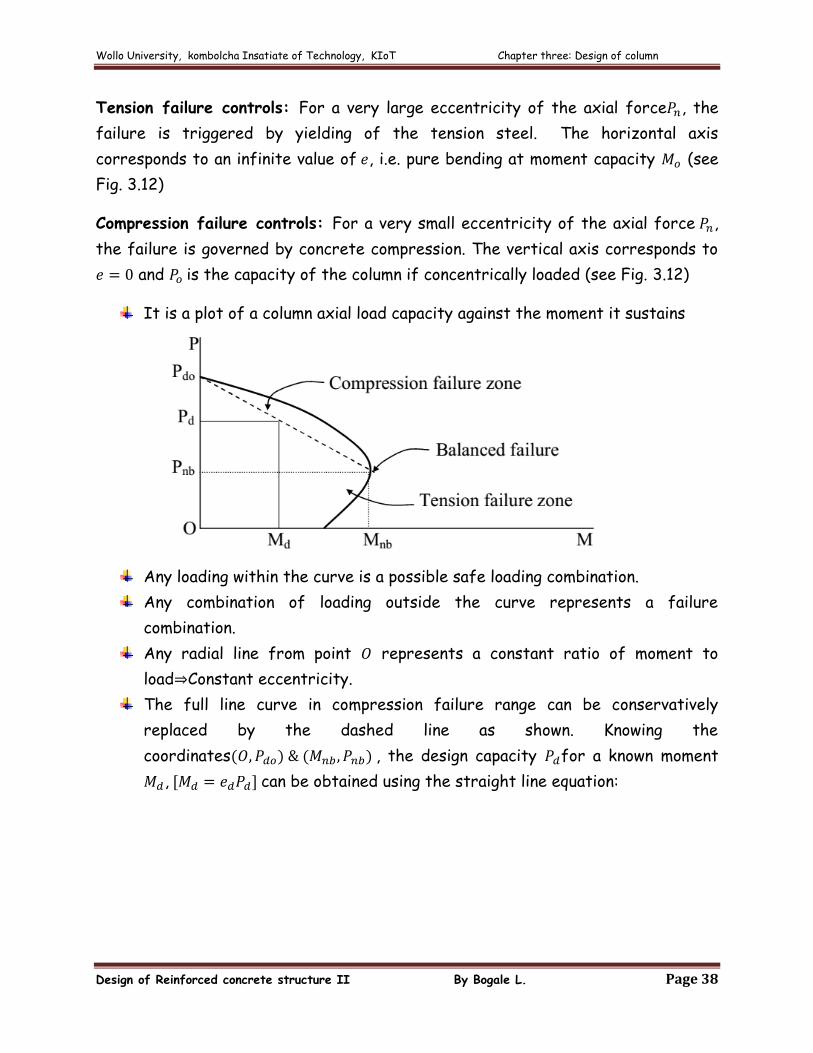
Tension failure controls: For a very large eccentricity of the axial force , the
failure is triggered by yielding of the tension steel. The horizontal axis
corresponds to an infinite value of , i.e. pure bending at moment capacity (see
Fig. 3.12)
Compression failure controls: For a very small eccentricity of the axial force ,
the failure is governed by concrete compression. The vertical axis corresponds to
and is the capacity of the column if concentrically loaded (see Fig. 3.12)
It is a plot of a column axial load capacity against the moment it sustains
Any loading within the curve is a possible safe loading combination.
Any combination of loading outside the curve represents a failure
combination.
Any radial line from point represents a constant ratio of moment to
load Constant eccentricity.
The full line curve in compression failure range can be conservatively
replaced by the dashed line as shown. Knowing the
coordinates , the design capacity for a known moment
, can be obtained using the straight line equation:
Wollo University, kombolcha Insatiate of Technology, KIoT Chapter three: Design of column
Design of Reinforced concrete structure II By Bogale L. Page 39
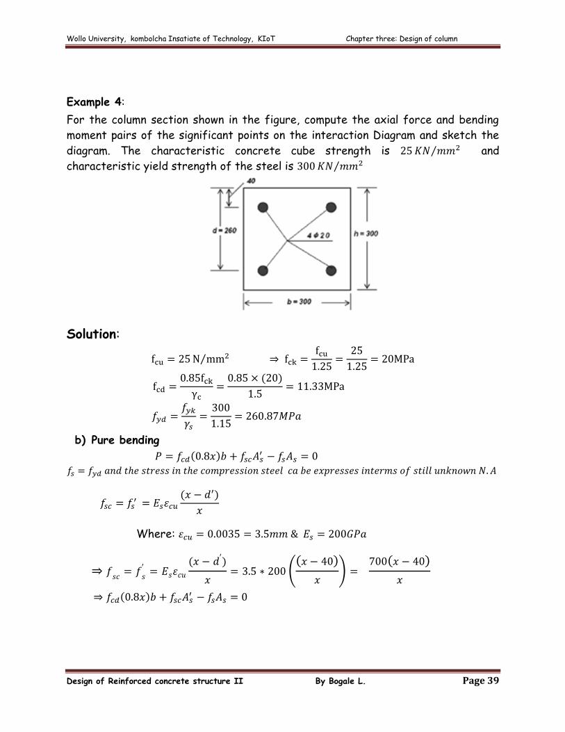
Example 4:
For the column section shown in the figure, compute the axial force and bending
moment pairs of the significant points on the interaction Diagram and sketch the
diagram. The characteristic concrete cube strength is and
characteristic yield strength of the steel is
Solution:
b) Pure bending
Where:
Wollo University, kombolcha Insatiate of Technology, KIoT Chapter three: Design of column
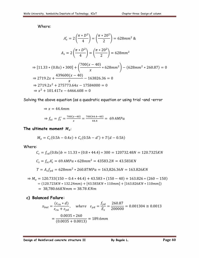
Design of Reinforced concrete structure II By Bogale L. Page 40
Where:
Solving the above equation (as a quadratic equation or using trial –and –error
The ultimate moment
Where:
c) Balanced Failure:
Wollo University, kombolcha Insatiate of Technology, KIoT Chapter three: Design of column
Design of Reinforced concrete structure II By Bogale L. Page 41
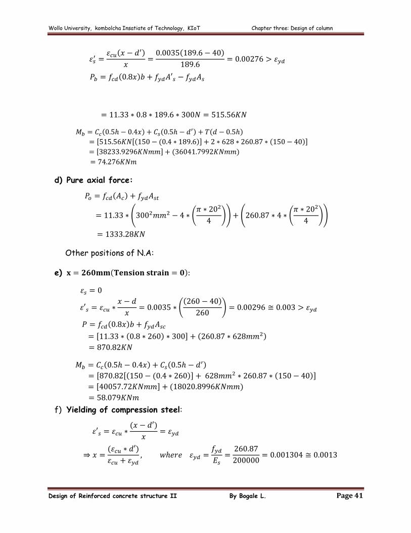
d) Pure axial force:
Other positions of N.A:
e)
f) Yielding of compression steel:
Wollo University, kombolcha Insatiate of Technology, KIoT Chapter three: Design of column
Design of Reinforced concrete structure II By Bogale L. Page 42
Wollo University, kombolcha Insatiate of Technology, KIoT Chapter three: Design of column
Design of Reinforced concrete structure II By Bogale L. Page 43
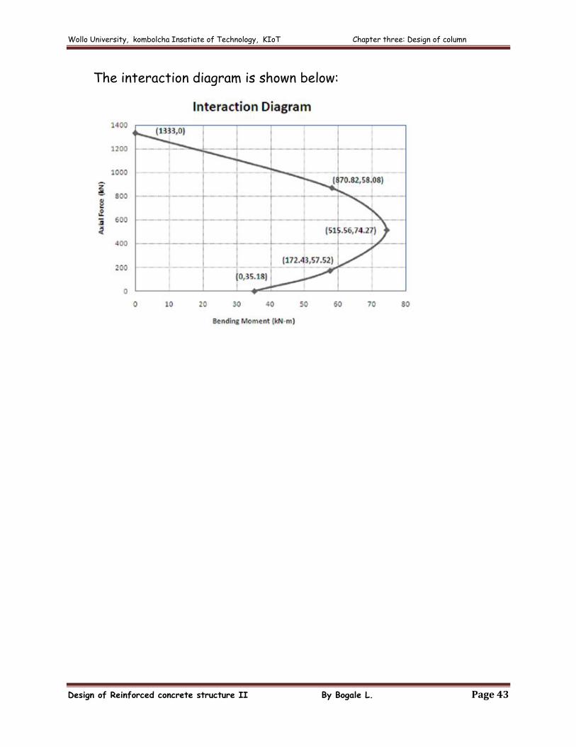
The interaction diagram is shown below:
Wollo University, kombolcha Insatiate of Technology, KIoT Chapter three: Design of column
Design of Reinforced concrete structure II By Bogale L. Page 44
3.7. Design of Columns for uniaxial Bending
Given and , the design requires the following procedure.
A trial cross section and steel area are selected.
The section in question is investigated which load combination it can
sustain. More suitably, for a fixed value of , determine (its capacity)
such that.
If , safe but is it economical
If , Unsafe, choose new cross section and /or
Where:
Thus, the trial shall be repeated until the value of is close enough and
Interaction diagrams for columns are generally computed by assuming a
series of strain distributions, each corresponding to a particular point on the
interaction diagram, and computing the corresponding values of and
(strain compatibility analysis).
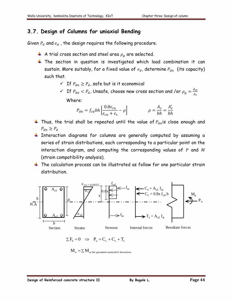
The calculation process can be illustrated as follow for one particular strain
distribution.
N.Adh
b
As2
As1
fcdfsc
fst
x0.8x
Mu
Pu
Cs = As1 fsc
Ts = As2 fst
Cc = 0.8x fcd b
Section Strains Stresses Internal forces Resultant forces
s1
s2
cu = 0.0035
T C C P 0 F sscuh
section theof centroid geometric at theu M M
Wollo University, kombolcha Insatiate of Technology, KIoT Chapter three: Design of column
Design of Reinforced concrete structure II By Bogale L. Page 45
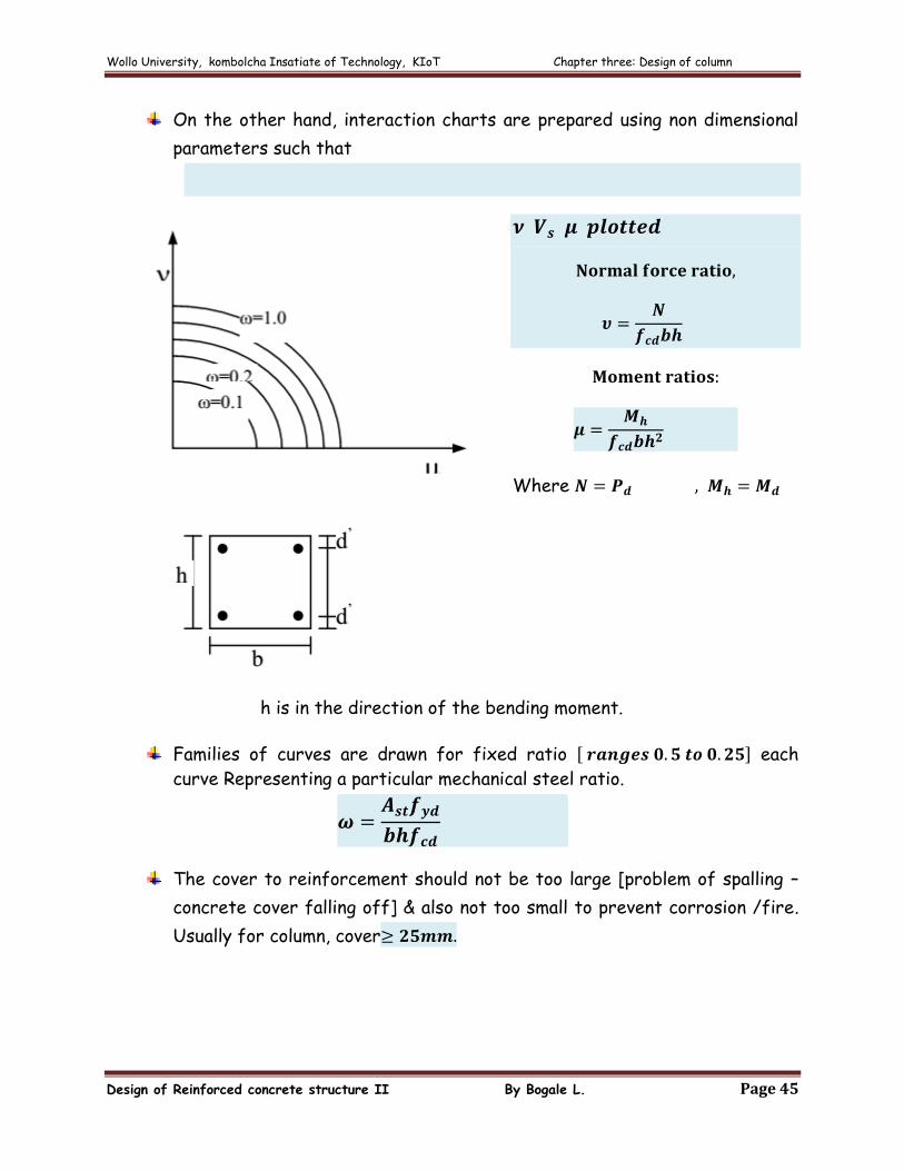
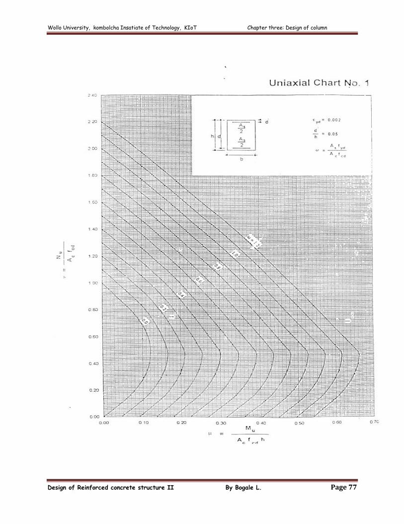
On the other hand, interaction charts are prepared using non dimensional
parameters such that
Where
h is in the direction of the bending moment.
Families of curves are drawn for fixed ratio each
curve Representing a particular mechanical steel ratio.
The cover to reinforcement should not be too large [problem of spalling –
concrete cover falling off] & also not too small to prevent corrosion /fire.
Usually for column, cover
Wollo University, kombolcha Insatiate of Technology, KIoT Chapter three: Design of column
Design of Reinforced concrete structure II By Bogale L. Page 46
In the actual design, interaction charts prepared for uniaxial bending can be used.
The procedure involves:
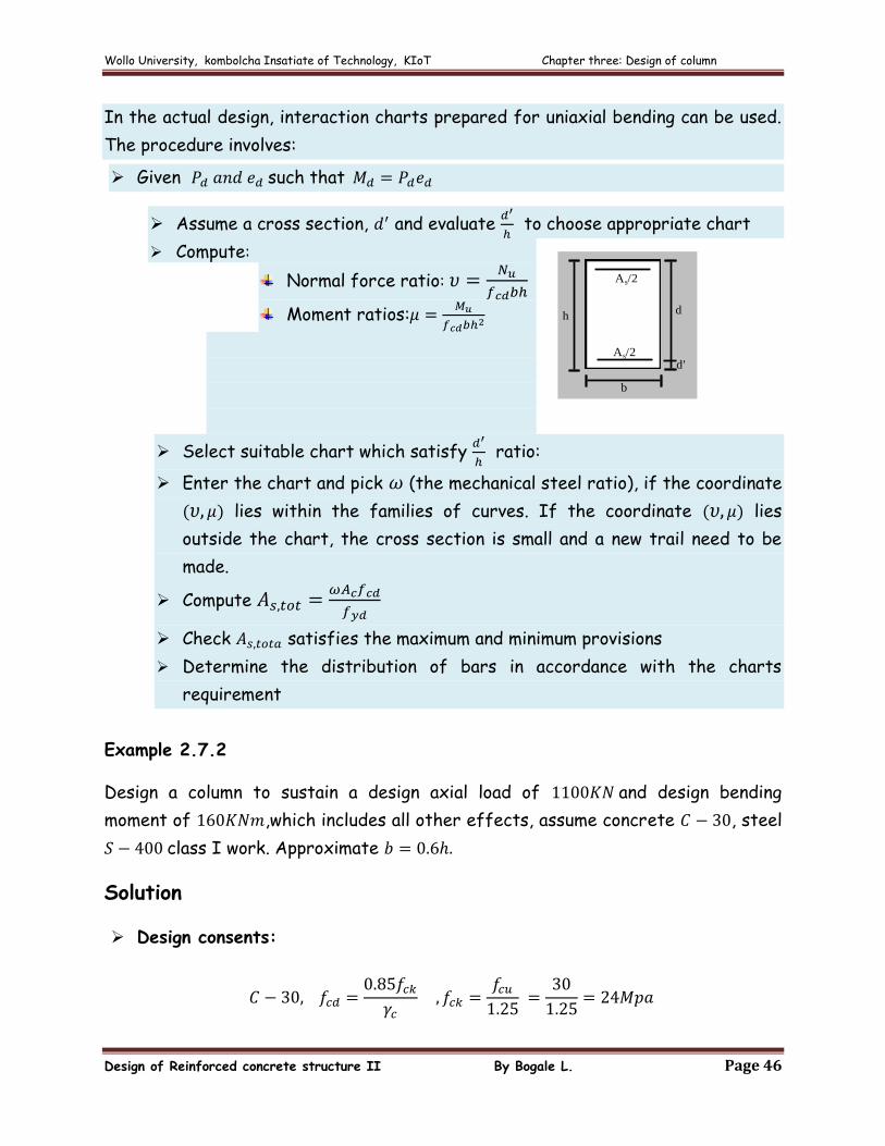
Given such that
Assume a cross section, and evaluate
to choose appropriate chart
Compute:
Normal force ratio:
Moment ratios:
Select suitable chart which satisfy
ratio:
Enter the chart and pick (the mechanical steel ratio), if the coordinate
lies within the families of curves. If the coordinate lies
outside the chart, the cross section is small and a new trail need to be
made.
Compute
Check satisfies the maximum and minimum provisions
Determine the distribution of bars in accordance with the charts
requirement
Example 2.7.2
Design a column to sustain a design axial load of and design bending
moment of ,which includes all other effects, assume concrete , steel
class I work. Approximate
Solution
Design consents:
h
b
As/2
As/2
d
d'
Wollo University, kombolcha Insatiate of Technology, KIoT Chapter three: Design of column
Design of Reinforced concrete structure II By Bogale L. Page 47
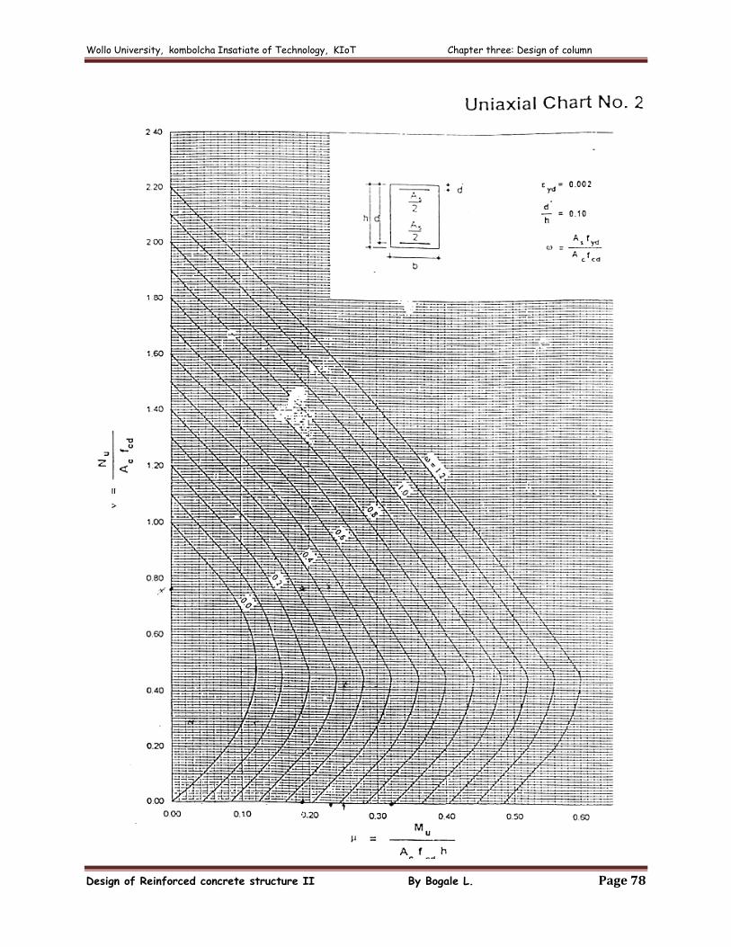
Using uniaxial chart number 2,
Determine Reinforcement:
Check :
The minimum reinforcement:
Therefore, it is ok!
Wollo University, kombolcha Insatiate of Technology, KIoT Chapter three: Design of column
Design of Reinforced concrete structure II By Bogale L. Page 48
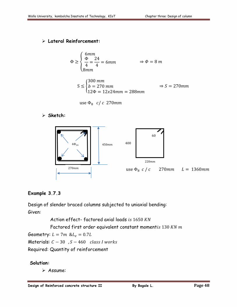
Lateral Reinforcement:
Sketch:
Example 3.7.3
Design of slender braced columns subjected to uniaxial bending:
Given:
Action effect- factored axial loads
Factored first order equivalent constant moment
Geometry:
Materials:
Required: Quantity of reinforcement
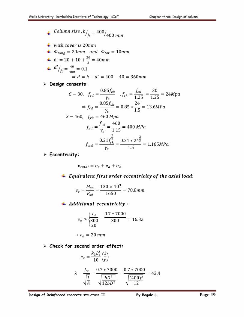
Solution:
Assume:
Wollo University, kombolcha Insatiate of Technology, KIoT Chapter three: Design of column
Design of Reinforced concrete structure II By Bogale L. Page 49
Design consents:
Eccentricity:
Check for second order effect:
Wollo University, kombolcha Insatiate of Technology, KIoT Chapter three: Design of column
Design of Reinforced concrete structure II By Bogale L. Page 50
Therefore, second order effect should be considered.
Critical value of corresponding to first order effect including
additional eccentricity ,
Using uniaxial chart Number 2,
Wollo University, kombolcha Insatiate of Technology, KIoT Chapter three: Design of column
Design of Reinforced concrete structure II By Bogale L. Page 51
Determine Reinforcement:
The minimum reinforcement:
Hence, is which in the required range.
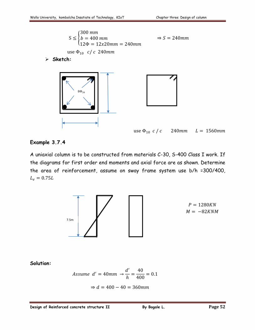
Lateral Reinforcement:
Wollo University, kombolcha Insatiate of Technology, KIoT Chapter three: Design of column
Design of Reinforced concrete structure II By Bogale L. Page 52
Sketch:
Example 3.7.4
A uniaxial column is to be constructed from materials C-30, S-400 Class I work. If
the diagrams for first order end moments and axial force are as shown. Determine
the area of reinforcement, assume on sway frame system use b/h =300/400,
Solution:
7.5m
Wollo University, kombolcha Insatiate of Technology, KIoT Chapter three: Design of column
Design of Reinforced concrete structure II By Bogale L. Page 53
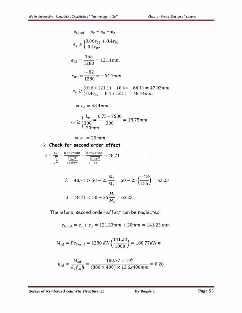
Check for second order effect
,
Therefore, second order effect can be neglected.
Wollo University, kombolcha Insatiate of Technology, KIoT Chapter three: Design of column
Design of Reinforced concrete structure II By Bogale L. Page 54
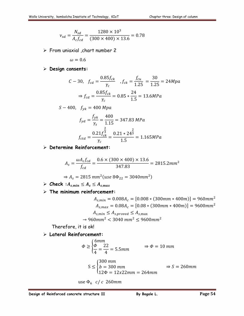
From uniaxial ,chart number 2
Design consents:
Determine Reinforcement:
Check :
The minimum reinforcement:
Therefore, it is ok!
Lateral Reinforcement:
Wollo University, kombolcha Insatiate of Technology, KIoT Chapter three: Design of column
Design of Reinforced concrete structure II By Bogale L. Page 55
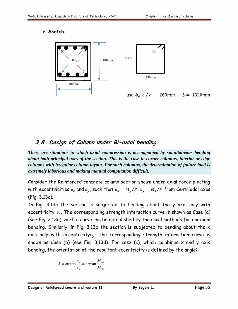
Sketch:
3.8 Design of Column under Bi-axial bending
There are situations in which axial compression is accompanied by simultaneous bending
about both principal axes of the section. This is the case in corner columns, interior or edge
columns with irregular column layout. For such columns, the determination of failure load is
extremely laborious and making manual computation difficult.
Consider the Reinforced concrete column section shown under axial force p acting
with eccentricities and , such that , from Centriodal axes
(Fig. 3.13c).
In Fig. 3.13a the section is subjected to bending about the y axis only with
eccentricity . The corresponding strength interaction curve is shown as Case (a)
(see Fig. 3.13d). Such a curve can be established by the usual methods for uni-axial
bending. Similarly, in Fig. 3.13b the section is subjected to bending about the x
axis only with eccentricity . The corresponding strength interaction curve is
shown as Case (b) (see Fig. 3.13d). For case (c), which combines x and y axis
bending, the orientation of the resultant eccentricity is defined by the angle:
nx
ny
y
x
M
M
e
earctanarctan
Wollo University, kombolcha Insatiate of Technology, KIoT Chapter three: Design of column
Design of Reinforced concrete structure II By Bogale L. Page 56
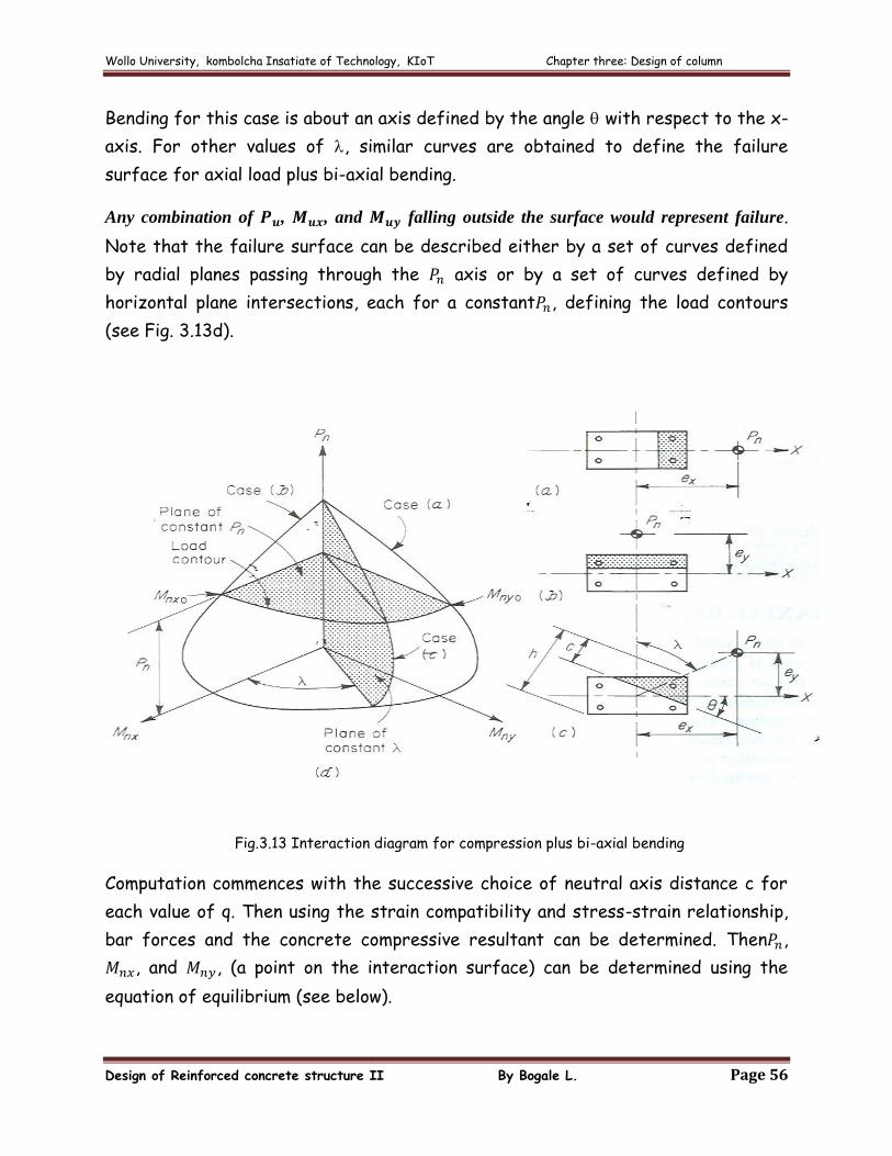
Bending for this case is about an axis defined by the angle with respect to the x-
axis. For other values of , similar curves are obtained to define the failure
surface for axial load plus bi-axial bending.
Any combination of , , and falling outside the surface would represent failure.
Note that the failure surface can be described either by a set of curves defined
by radial planes passing through the axis or by a set of curves defined by
horizontal plane intersections, each for a constant , defining the load contours
(see Fig. 3.13d).
Fig.3.13 Interaction diagram for compression plus bi-axial bending
Computation commences with the successive choice of neutral axis distance c for
each value of q. Then using the strain compatibility and stress-strain relationship,
bar forces and the concrete compressive resultant can be determined. Then ,
, and , (a point on the interaction surface) can be determined using the
equation of equilibrium (see below).
Wollo University, kombolcha Insatiate of Technology, KIoT Chapter three: Design of column
Design of Reinforced concrete structure II By Bogale L. Page 57
(1*) P P P P 0 F stsccnh
Where:
concretein forceresultant , fA P icic
steeln compressioin force ecompressivresultant , fA P sciscisc
steel in tension force tensileresultant , fA P stistist
(2*) yfA yfA yfA M stististiscisciscicicicinx
(3*) xfA xfA xfA M stististisciscisciciciciny
Since the determination of the neutral axis requires several trials, the procedure
using the above expressions is tedious. Thus, the following simple approximate
methods are widely used.
i. Load contour method: It is an approximation on load versus moment interaction
surface (see Fig. 3.13). Accordingly, the general non-dimensional interaction
equation of family of load contours is given by:
1M
M
M
M
dyo
dy
dxo
dx
nn
2.0 1.15 and p
p1.667 0.667 n
do
da
n
Where:
ii. Reciprocal method/Bresler’s equation: It is an approximation of bowl shaped
failure surface by the following reciprocal load interaction equation.
dodyodxodx pppp
1111
Where:
design (ultimate) load capacity of the section with eccentricities &
Wollo University, kombolcha Insatiate of Technology, KIoT Chapter three: Design of column
Design of Reinforced concrete structure II By Bogale L. Page 58
ultimate load capacity of the section for uni axial bending with only
ultimate load capacity of the section for uni axial bending with only
concentric axial load capacity
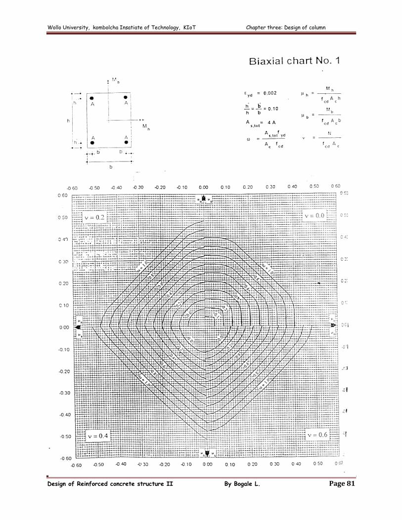
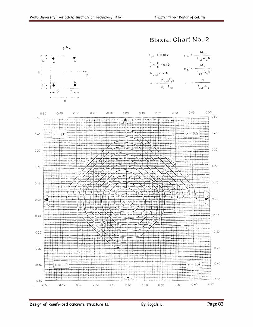
However interaction charts prepared for biaxial bending can be used for actual
design. The procedure involves:
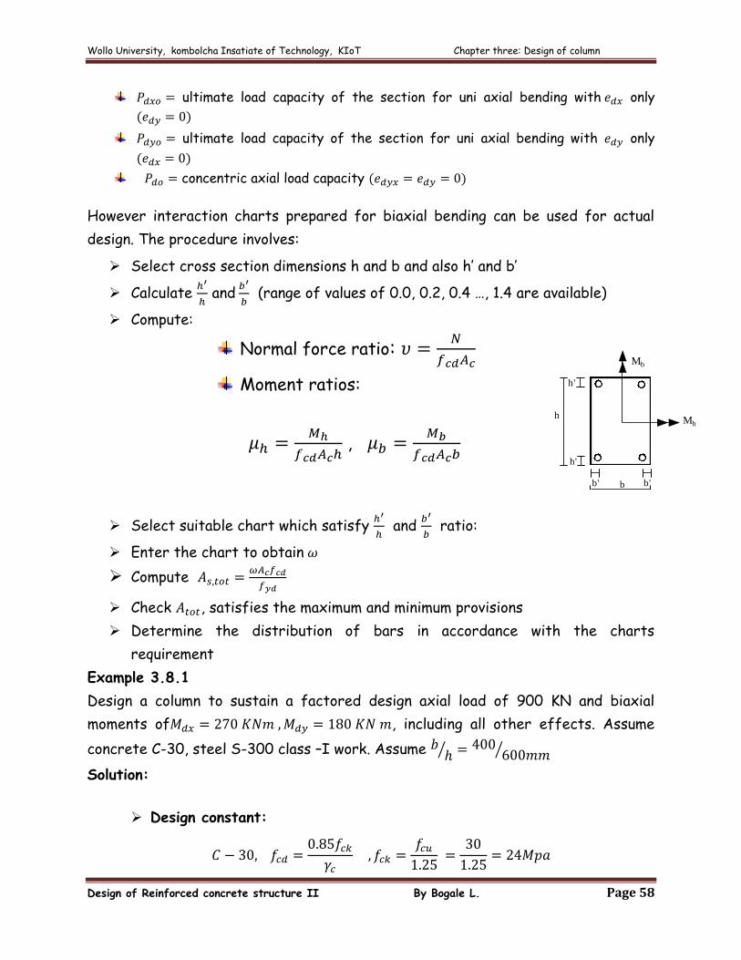
Select cross section dimensions h and b and also h’ and b’
Calculate
and
(range of values of 0.0, 0.2, 0.4 …, 1.4 are available)
Compute:
Normal force ratio:
Moment ratios:
,
Select suitable chart which satisfy
and
ratio:
Enter the chart to obtain
Compute
Check , satisfies the maximum and minimum provisions
Determine the distribution of bars in accordance with the charts
requirement
Example 3.8.1
Design a column to sustain a factored design axial load of 900 KN and biaxial
moments of , including all other effects. Assume
concrete C-30, steel S-300 class –I work. Assume
Solution:
Design constant:
h
b b'b'
h'
h'
Mb
Mh
Wollo University, kombolcha Insatiate of Technology, KIoT Chapter three: Design of column
Design of Reinforced concrete structure II By Bogale L. Page 59
Therefore, interpolate to obtain
Using biaxial chart Number 9
By interpolate for
Determine Reinforcement:
Wollo University, kombolcha Insatiate of Technology, KIoT Chapter three: Design of column
Design of Reinforced concrete structure II By Bogale L. Page 60
Check :
he minimum reinforcement:
Wollo University, kombolcha Insatiate of Technology, KIoT Chapter three: Design of column
Design of Reinforced concrete structure II By Bogale L. Page 61
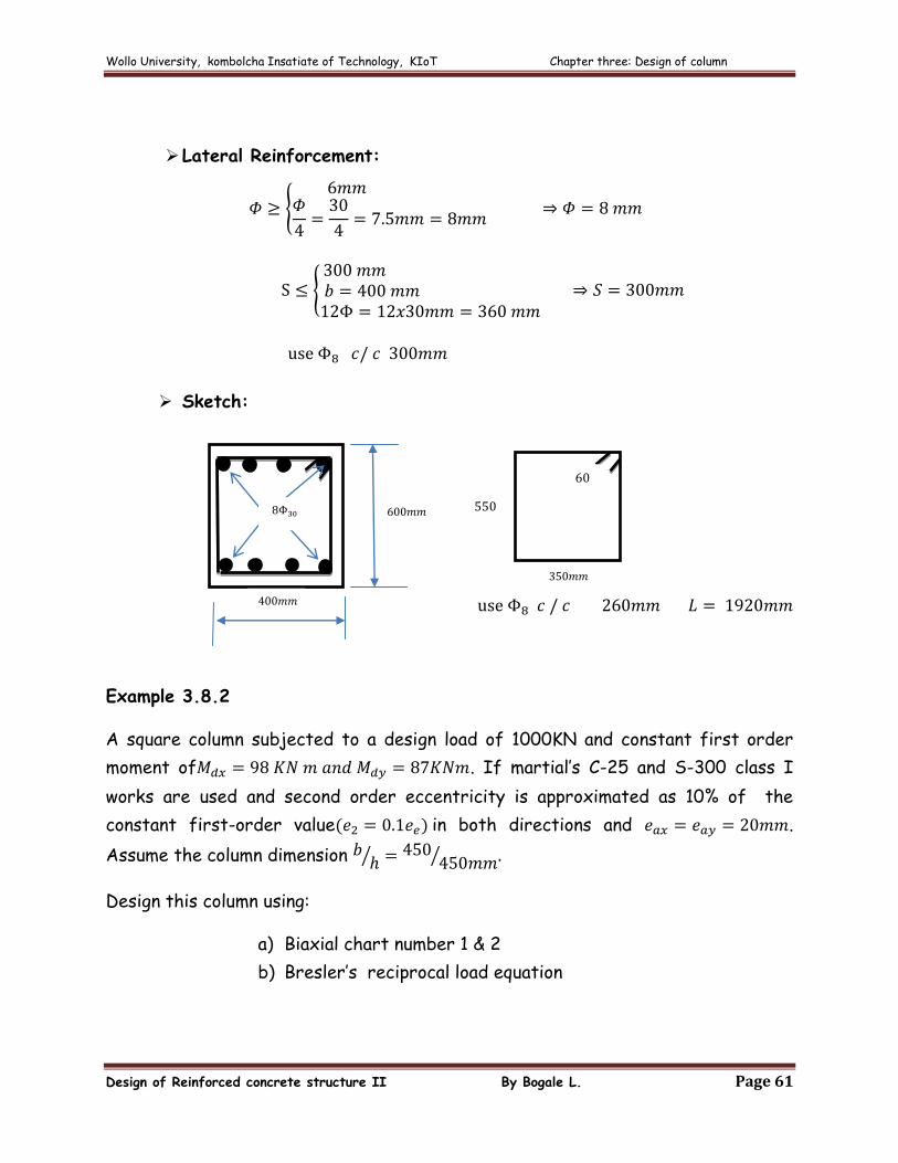
Lateral Reinforcement:
Sketch:
Example 3.8.2
A square column subjected to a design load of 1000KN and constant first order
moment of . If martial’s C-25 and S-300 class I
works are used and second order eccentricity is approximated as 10% of the
constant first-order value in both directions and .
Assume the column dimension
Design this column using:
a) Biaxial chart number 1 & 2
b) Bresler’s reciprocal load equation
Wollo University, kombolcha Insatiate of Technology, KIoT Chapter three: Design of column
Design of Reinforced concrete structure II By Bogale L. Page 62
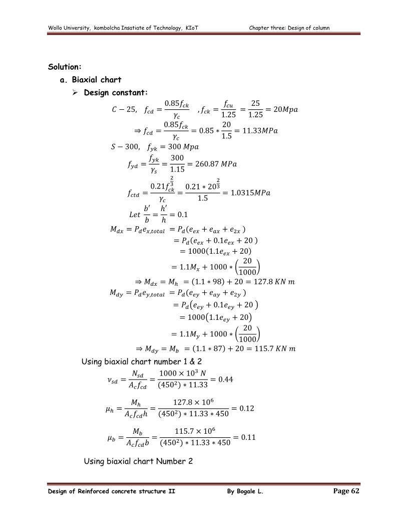
Solution:
a. Biaxial chart
Design constant:
Using biaxial chart number 1 & 2
Using biaxial chart Number 2
Wollo University, kombolcha Insatiate of Technology, KIoT Chapter three: Design of column
Design of Reinforced concrete structure II By Bogale L. Page 63
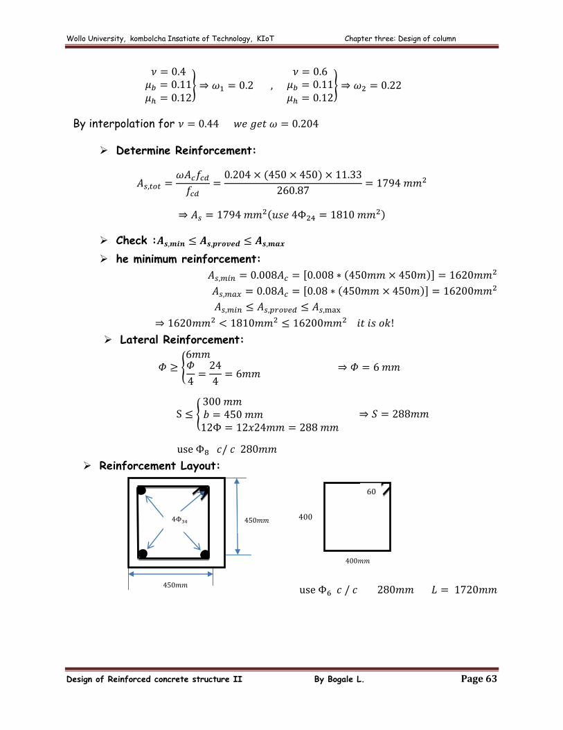
By interpolation for
Determine Reinforcement:
Check :
he minimum reinforcement:
Lateral Reinforcement:
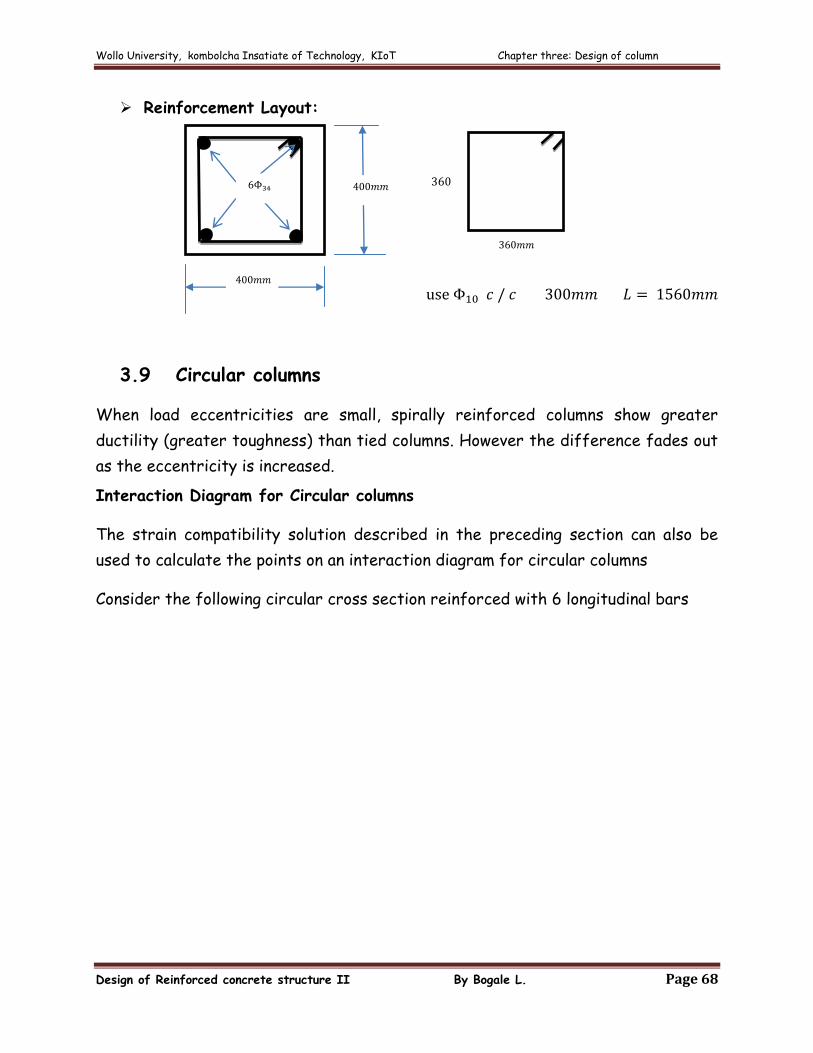
Reinforcement Layout:
Wollo University, kombolcha Insatiate of Technology, KIoT Chapter three: Design of column
Design of Reinforced concrete structure II By Bogale L. Page 64
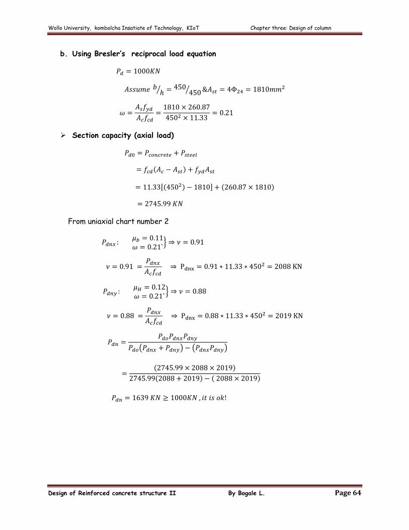
b. Using Bresler’s reciprocal load equation
Section capacity (axial load)
From uniaxial chart number 2
Wollo University, kombolcha Insatiate of Technology, KIoT Chapter three: Design of column
Design of Reinforced concrete structure II By Bogale L. Page 65
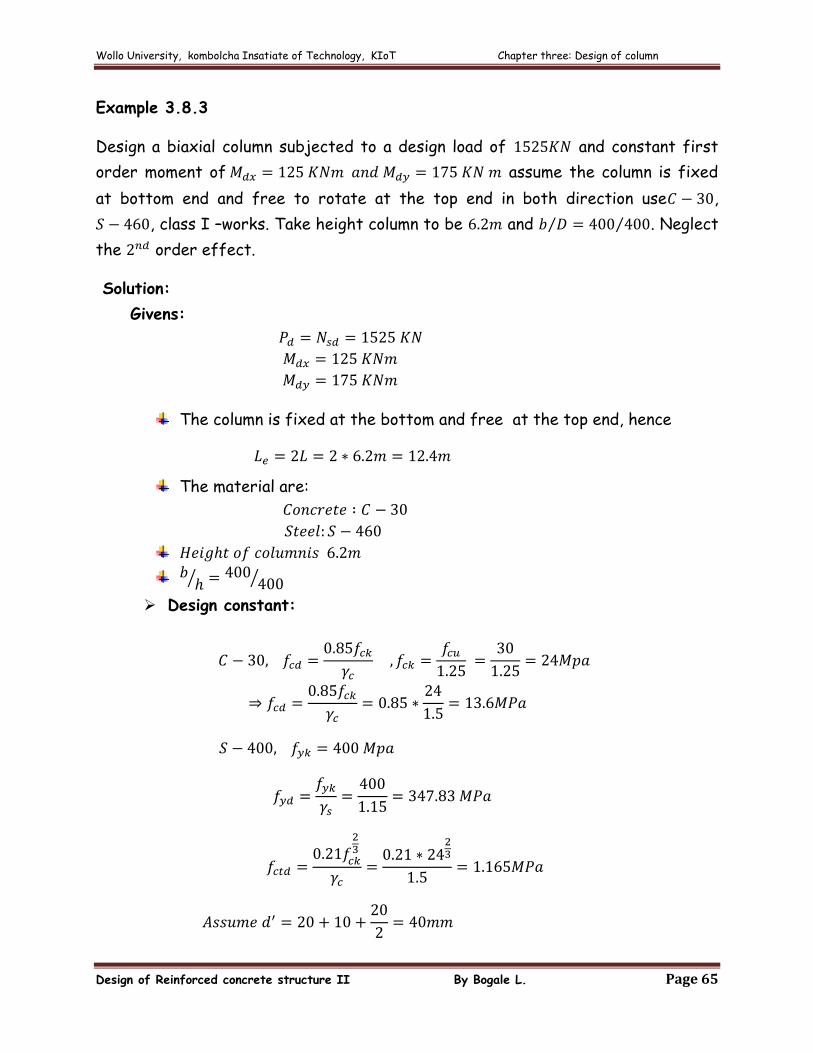
Example 3.8.3
Design a biaxial column subjected to a design load of and constant first
order moment of assume the column is fixed
at bottom end and free to rotate at the top end in both direction use ,
, class I –works. Take height column to be and . Neglect
the order effect.
Solution:
Givens:
The column is fixed at the bottom and free at the top end, hence
The material are:
Design constant:
Wollo University, kombolcha Insatiate of Technology, KIoT Chapter three: Design of column
Design of Reinforced concrete structure II By Bogale L. Page 66
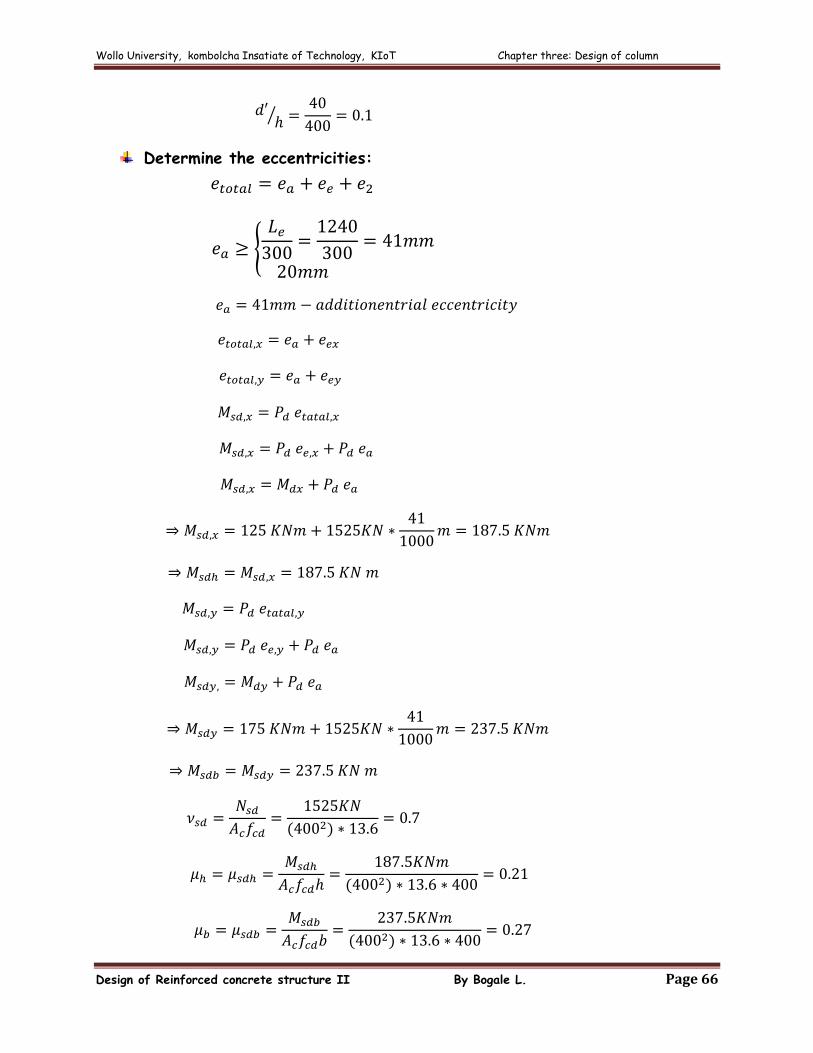
Determine the eccentricities:
Wollo University, kombolcha Insatiate of Technology, KIoT Chapter three: Design of column
Design of Reinforced concrete structure II By Bogale L. Page 67
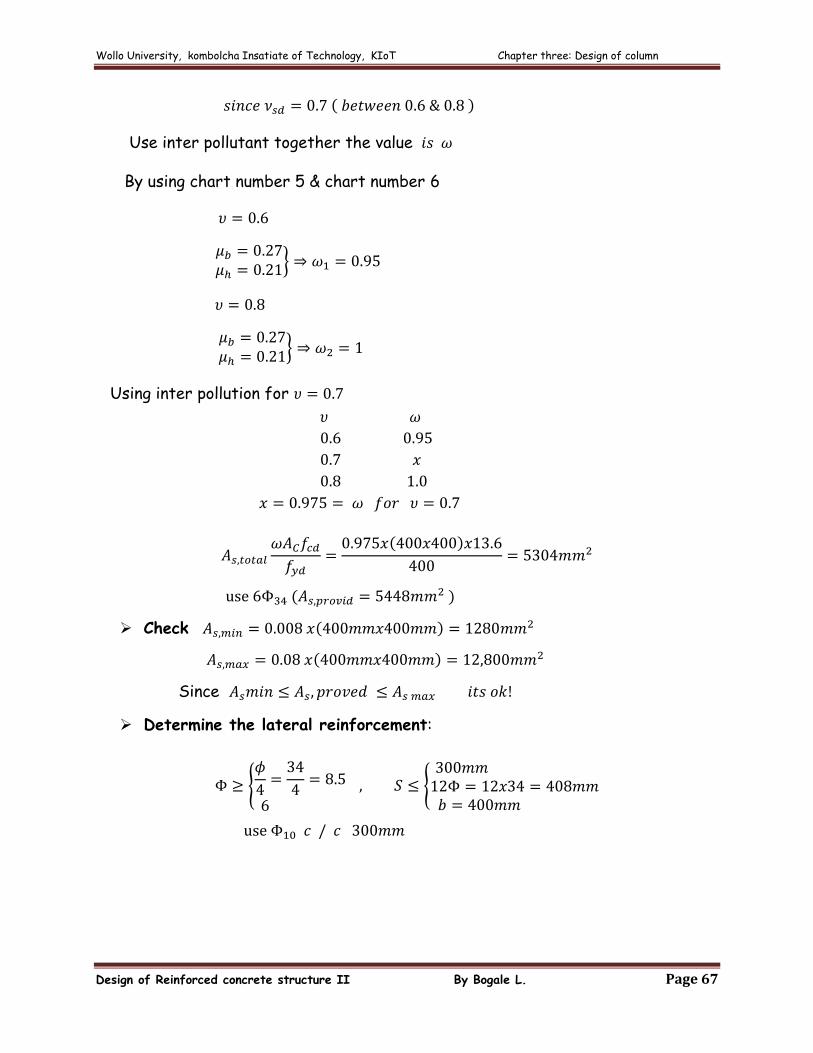
Use inter pollutant together the value
By using chart number 5 & chart number 6
Using inter pollution for
Check
Since
Determine the lateral reinforcement:
Wollo University, kombolcha Insatiate of Technology, KIoT Chapter three: Design of column
Design of Reinforced concrete structure II By Bogale L. Page 68
Reinforcement Layout:
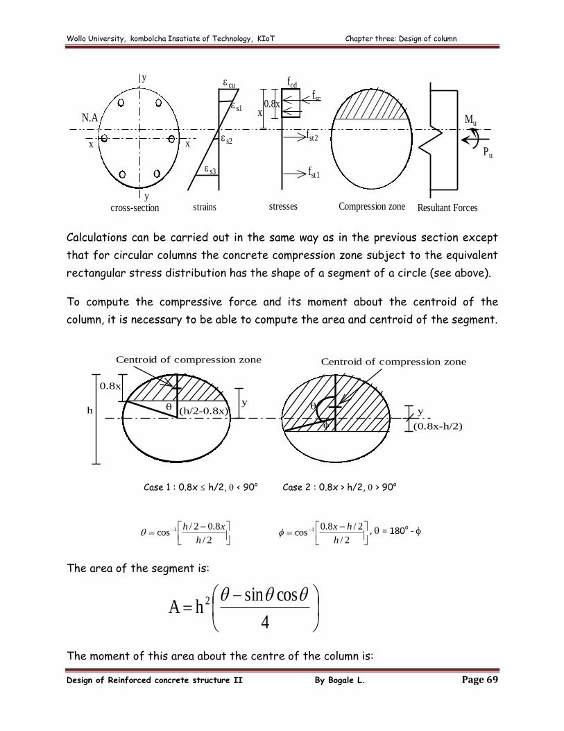
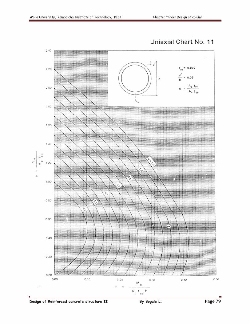
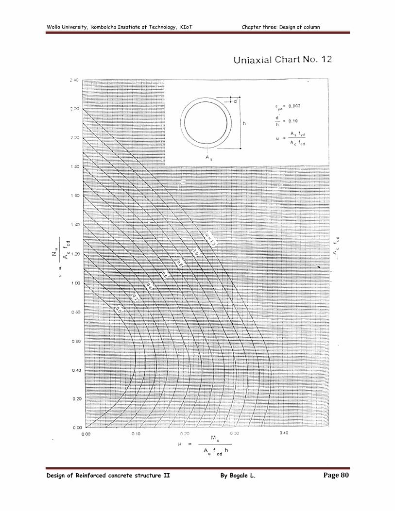
3.9 Circular columns
When load eccentricities are small, spirally reinforced columns show greater
ductility (greater toughness) than tied columns. However the difference fades out
as the eccentricity is increased.
Interaction Diagram for Circular columns
The strain compatibility solution described in the preceding section can also be
used to calculate the points on an interaction diagram for circular columns
Consider the following circular cross section reinforced with 6 longitudinal bars
Wollo University, kombolcha Insatiate of Technology, KIoT Chapter three: Design of column
Design of Reinforced concrete structure II By Bogale L. Page 69
N.A
cross-section strains stresses
s1
s3
cu
s2
fcd
fsc
fst1
x0.8x
fst2
Mu
Pu
Compression zone Resultant Forces
y
y
xx
Calculations can be carried out in the same way as in the previous section except
that for circular columns the concrete compression zone subject to the equivalent
rectangular stress distribution has the shape of a segment of a circle (see above).
To compute the compressive force and its moment about the centroid of the
column, it is necessary to be able to compute the area and centroid of the segment.
Centroid of compression zone
y
(0.8x-h/2)
(h/2-0.8x)h
0.8x
y
Centroid of compression zone
Case 1 : 0.8x h/2, < 90o Case 2 : 0.8x > h/2, > 90o
2/
8.02/cos 1
h
xh
2/
2/8.0cos 1
h
hx , = 180o -
The area of the segment is:
4
cossinh A 2
The moment of this area about the centre of the column is:
Wollo University, kombolcha Insatiate of Technology, KIoT Chapter three: Design of column
Design of Reinforced concrete structure II By Bogale L. Page 70
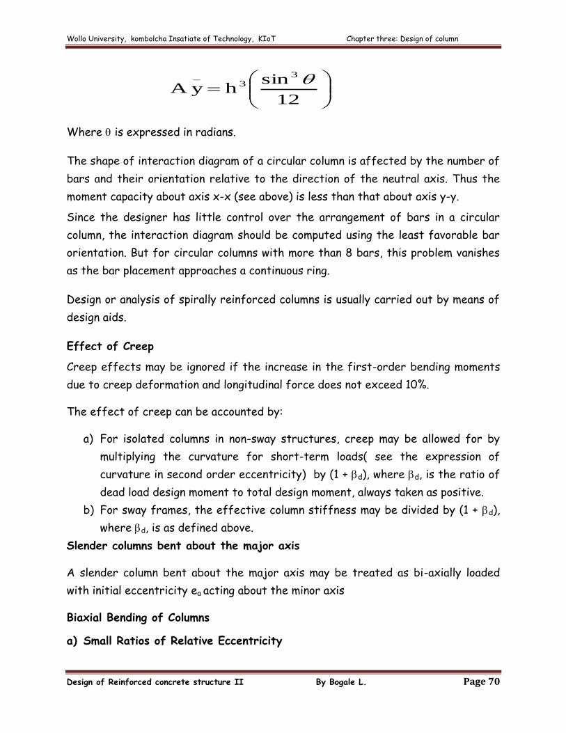
12
sinh yA
33
_
Where is expressed in radians.
The shape of interaction diagram of a circular column is affected by the number of
bars and their orientation relative to the direction of the neutral axis. Thus the
moment capacity about axis x-x (see above) is less than that about axis y-y.
Since the designer has little control over the arrangement of bars in a circular
column, the interaction diagram should be computed using the least favorable bar
orientation. But for circular columns with more than 8 bars, this problem vanishes
as the bar placement approaches a continuous ring.
Design or analysis of spirally reinforced columns is usually carried out by means of
design aids.
Effect of Creep
Creep effects may be ignored if the increase in the first-order bending moments
due to creep deformation and longitudinal force does not exceed 10%.
The effect of creep can be accounted by:
a) For isolated columns in non-sway structures, creep may be allowed for by
multiplying the curvature for short-term loads( see the expression of
curvature in second order eccentricity) by (1 + d), where d, is the ratio of
dead load design moment to total design moment, always taken as positive.
b) For sway frames, the effective column stiffness may be divided by (1 + d),
where d, is as defined above.
Slender columns bent about the major axis
A slender column bent about the major axis may be treated as bi-axially loaded
with initial eccentricity ea acting about the minor axis
Biaxial Bending of Columns
a) Small Ratios of Relative Eccentricity
Wollo University, kombolcha Insatiate of Technology, KIoT Chapter three: Design of column
Design of Reinforced concrete structure II By Bogale L. Page 71
Columns of rectangular cross-section which are subjected to biaxial bending
may be checked separately for uni-axial bending in each respective direction
provided the relative eccentricities are such that k 0.2; where k denotes the
ratio of the smaller relative eccentricity to the larger relative eccentricity.
The relative eccentricity, for a given direction, is defined as the ratio of the
total eccentricity, allowing for initial eccentricity and second-order effects in
that direction, to the column width in the same direction.
b) Approximate Method
Columns of rectangular cross-section which are subjected to biaxial bending
may be checked separately for uni-axial bending in each respective.
If the above condition is not satisfied, the following approximate method of
calculation can be used, in the absence of more accurate methods.
For this approximate method, one-fourth of the total reinforcement must
either be distributed along each face of the column or at each corner. The
column shall be designed for uni-axial bending with the following equivalent uni-
axial eccentricity of load, eeq along the axis parallel to the larger relative
eccentricity:
k1ee toteq
Where etot denotes the total eccentricity in the direction of the larger relative
eccentricity
K denotes the relative eccentricity ratio as defined in above.
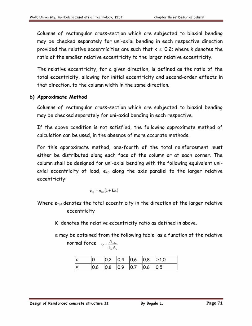
α may be obtained from the following table as a function of the relative
normal force ccd
usd
Af
N
0
0.2
0.4
0.6
0.8
1.0
0.6
0.8
0.9
0.7
0.6
0.5
Wollo University, kombolcha Insatiate of Technology, KIoT Chapter three: Design of column
Design of Reinforced concrete structure II By Bogale L. Page 72
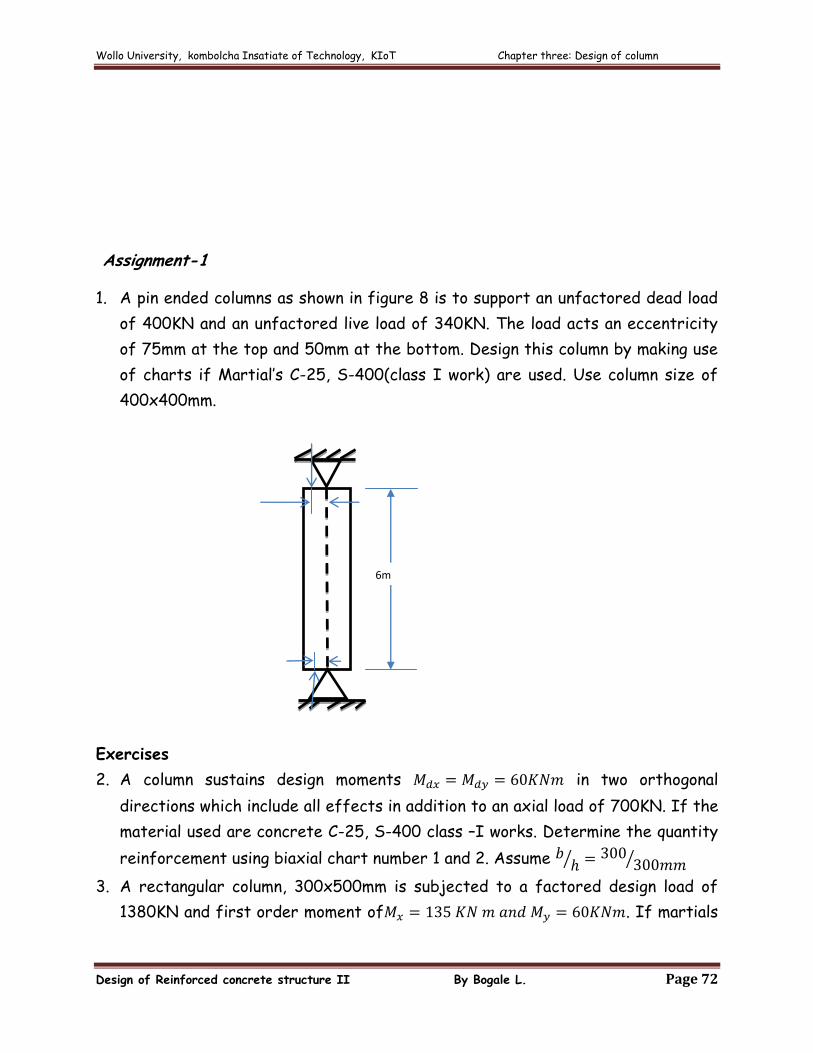
Assignment-1
1. A pin ended columns as shown in figure 8 is to support an unfactored dead load
of 400KN and an unfactored live load of 340KN. The load acts an eccentricity
of 75mm at the top and 50mm at the bottom. Design this column by making use
of charts if Martial’s C-25, S-400(class I work) are used. Use column size of
400x400mm.
Exercises
2. A column sustains design moments in two orthogonal
directions which include all effects in addition to an axial load of 700KN. If the
material used are concrete C-25, S-400 class –I works. Determine the quantity
reinforcement using biaxial chart number 1 and 2. Assume
3. A rectangular column, 300x500mm is subjected to a factored design load of
1380KN and first order moment of . If martials
6m
75mm
50mm
Wollo University, kombolcha Insatiate of Technology, KIoT Chapter three: Design of column
Design of Reinforced concrete structure II By Bogale L. Page 73
C-25 and S-400 class I works are used and second order eccentricity is
neglected in both directions and
a. Design this column using biaxial chart No. 9&10.
b. Verify your result in a using Bresler’s reciprocal load equation
4. Determine the quantity of reinforcement required in slender braced column to
resist a compressive force of 1400KN and first order moment of 145KNm and -
20KNm. Assume b=h=300mm,length of column ,
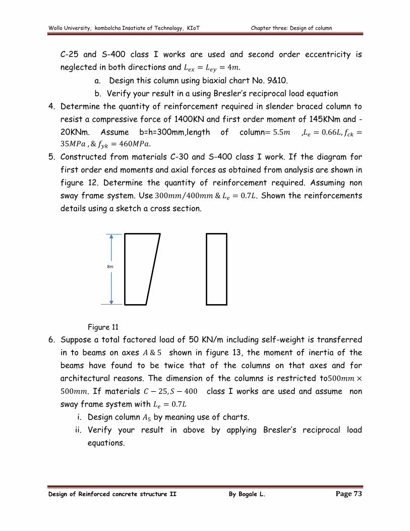
5. Constructed from materials C-30 and S-400 class I work. If the diagram for
first order end moments and axial forces as obtained from analysis are shown in
figure 12. Determine the quantity of reinforcement required. Assuming non
sway frame system. Use . Shown the reinforcements
details using a sketch a cross section.
Figure 11
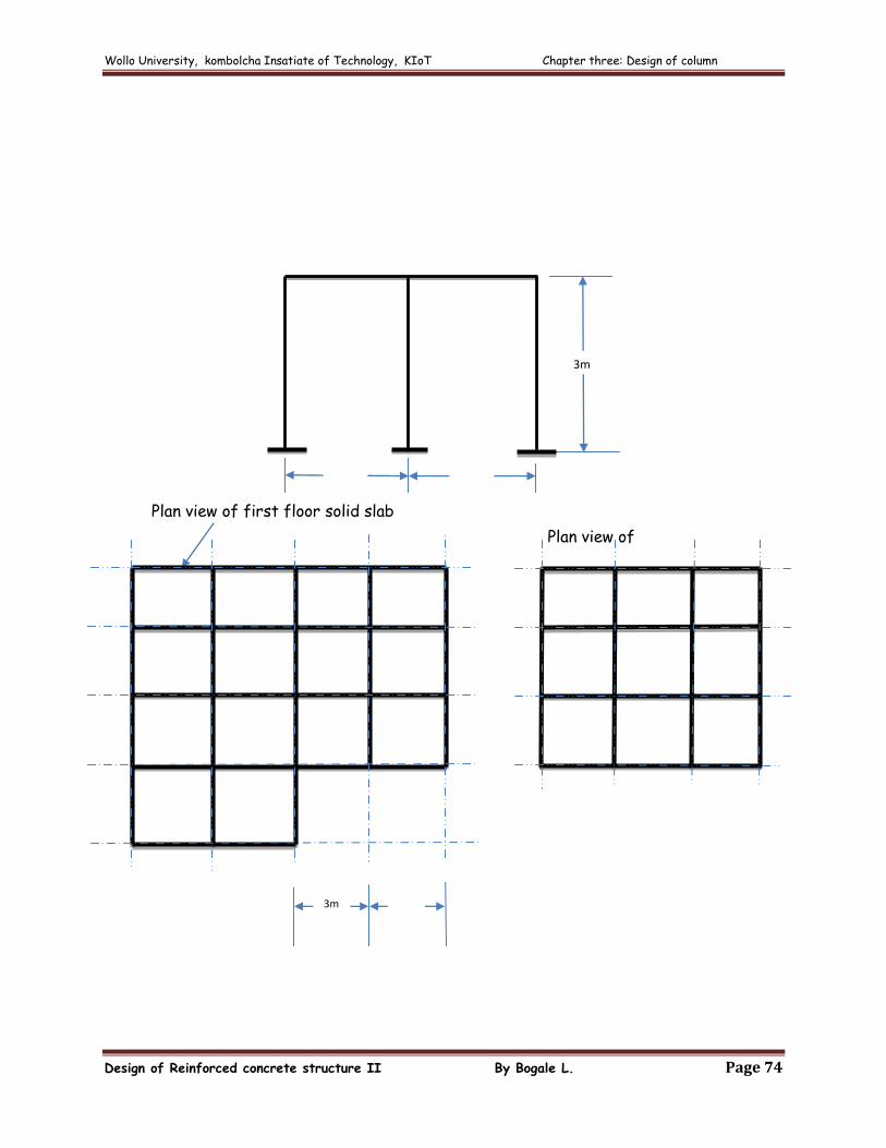
6. Suppose a total factored load of 50 KN/m including self-weight is transferred
in to beams on axes shown in figure 13, the moment of inertia of the
beams have found to be twice that of the columns on that axes and for
architectural reasons. The dimension of the columns is restricted to
. If materials class I works are used and assume non
sway frame system with
i. Design column by meaning use of charts.
ii. Verify your result in above by applying Bresler’s reciprocal load
equations.
BMD AFD
8m
90 KNm 1200 KN
1200 KN
Wollo University, kombolcha Insatiate of Technology, KIoT Chapter three: Design of column
Design of Reinforced concrete structure II By Bogale L. Page 74
Plan view of first floor solid slab
Plan view of
3m
6m 6m
3m 3m
A B C D E
5
4
1
2
3
B C D F
Wollo University, kombolcha Insatiate of Technology, KIoT Chapter three: Design of column
Design of Reinforced concrete structure II By Bogale L. Page 75
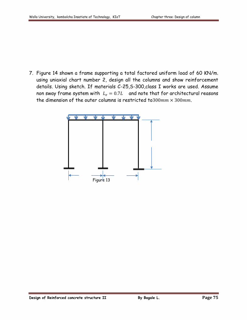
7. Figure 14 shown a frame supporting a total factored uniform load of 60 KN/m.
using uniaxial chart number 2, design all the columns and show reinforcement
details. Using sketch. If materials C-25,S-300,class I works are used. Assume
non sway frame system with and note that for architectural reasons
the dimension of the outer columns is restricted to .
Figure 13
3m
6m 6m
60 KN/m

Wollo University, kombolcha Insatiate of Technology, KIoT Chapter three: Design of column
Design of Reinforced concrete structure II By Bogale L. Page 76
Wollo University, kombolcha Insatiate of Technology, KIoT Chapter three: Design of column
Design of Reinforced concrete structure II By Bogale L. Page 77
Wollo University, kombolcha Insatiate of Technology, KIoT Chapter three: Design of column
Design of Reinforced concrete structure II By Bogale L. Page 78
Wollo University, kombolcha Insatiate of Technology, KIoT Chapter three: Design of column
Design of Reinforced concrete structure II By Bogale L. Page 79
Wollo University, kombolcha Insatiate of Technology, KIoT Chapter three: Design of column
Design of Reinforced concrete structure II By Bogale L. Page 80
Wollo University, kombolcha Insatiate of Technology, KIoT Chapter three: Design of column
Design of Reinforced concrete structure II By Bogale L. Page 81
Wollo University, kombolcha Insatiate of Technology, KIoT Chapter three: Design of column
Design of Reinforced concrete structure II By Bogale L. Page 82