Embed Size (px)
Citation preview

Chapter4 - MILLING PROCESS
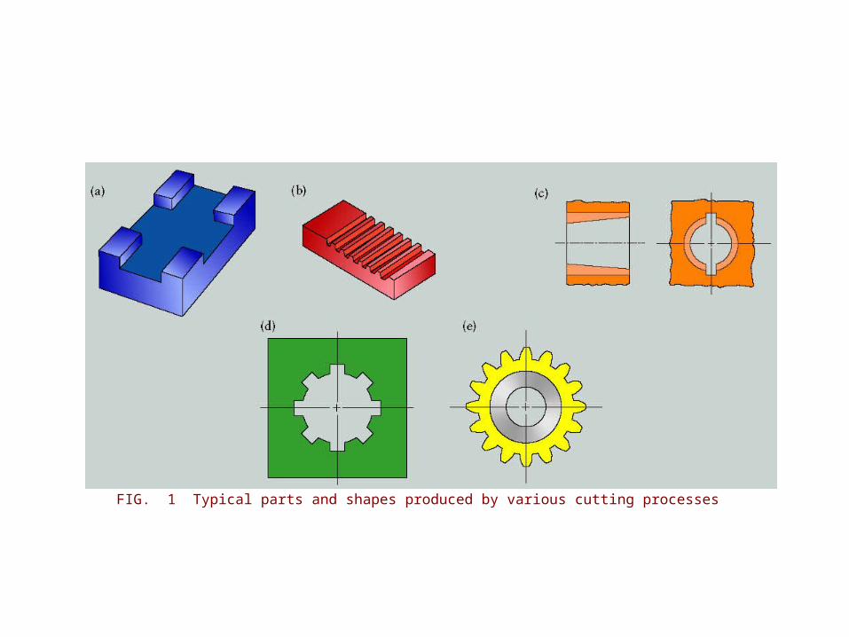
FIG. 1 Typical parts and shapes produced by various cutting processes
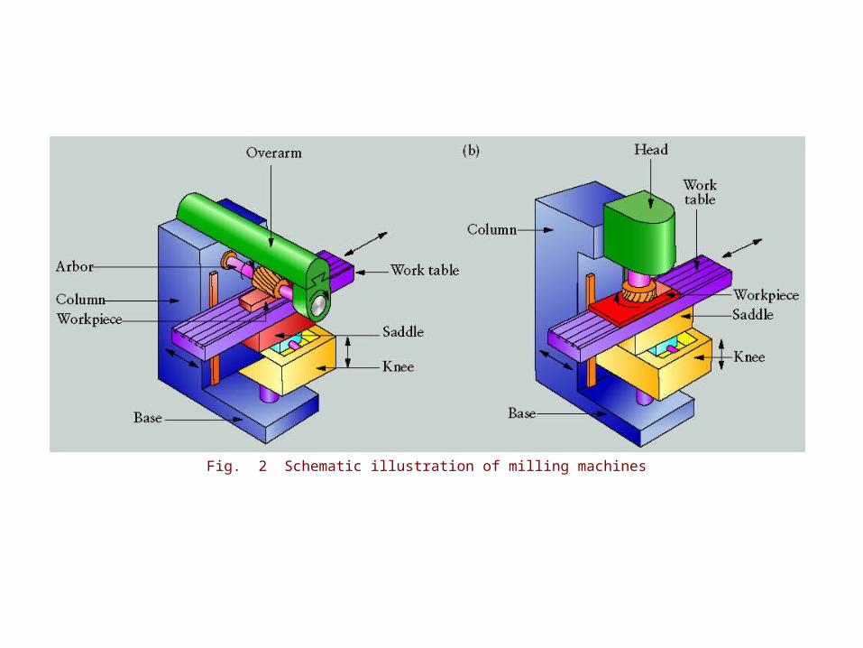
Fig. 2 Schematic illustration of milling machines
Fig. 3 Milling machines
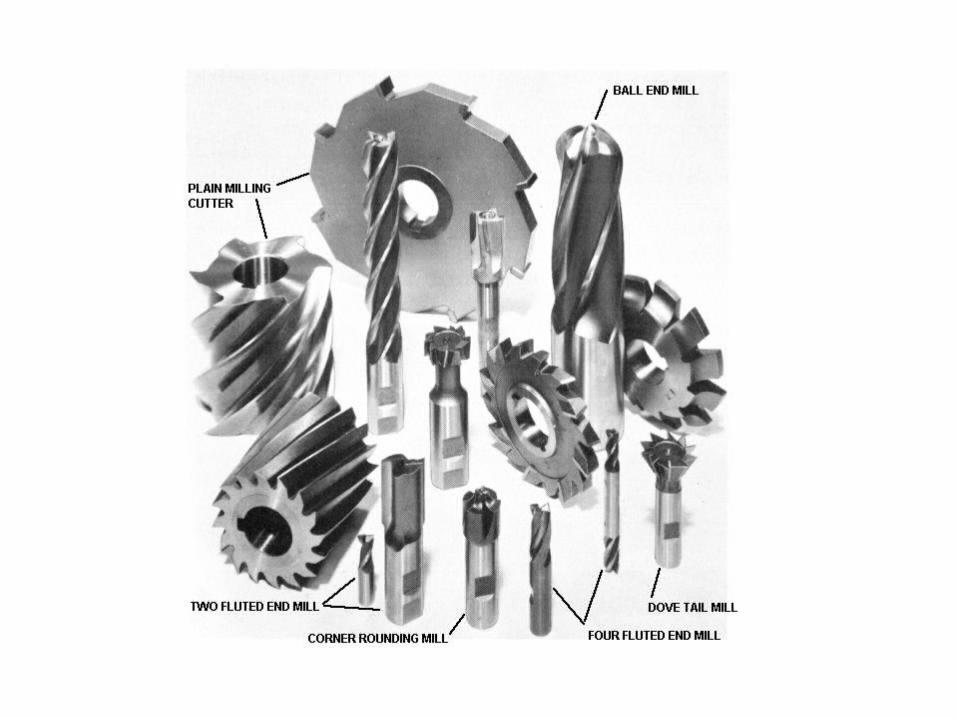
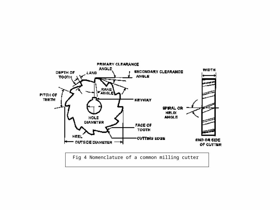
Fig 4 Nomenclature of a common milling cutter
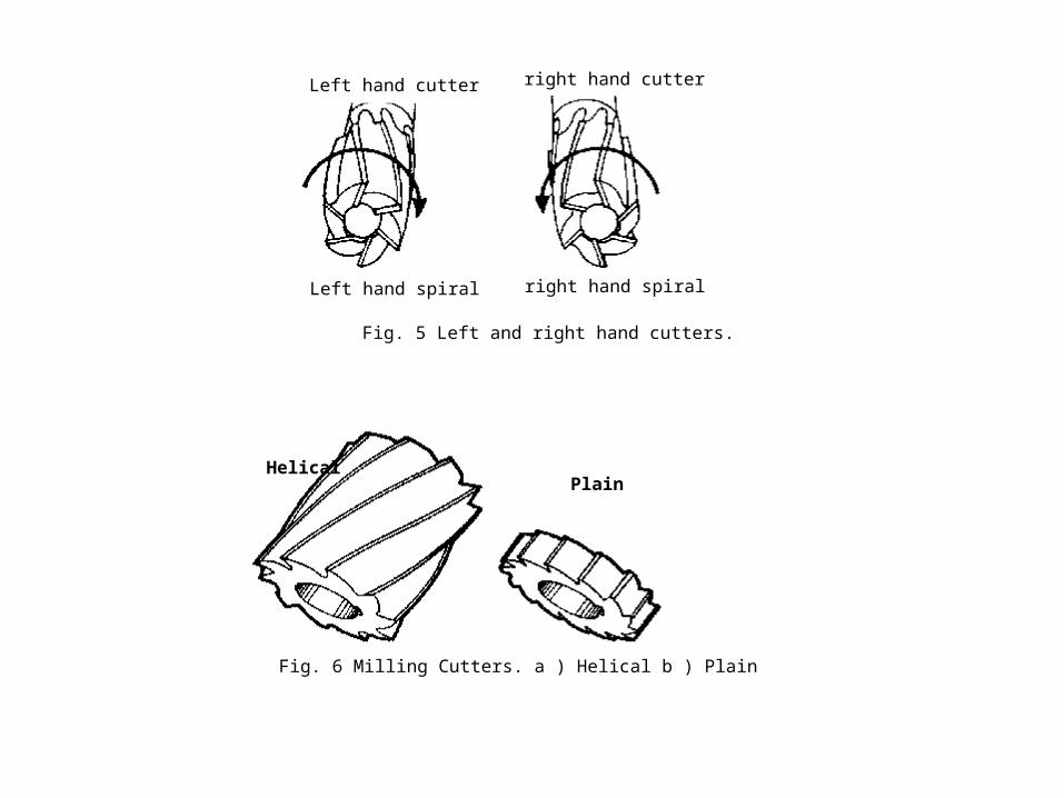
Left hand spiral right hand spiral
Left hand cutter right hand cutter
Fig. 5 Left and right hand cutters.
Helical Plain
Fig. 6 Milling Cutters. a ) Helical b ) Plain
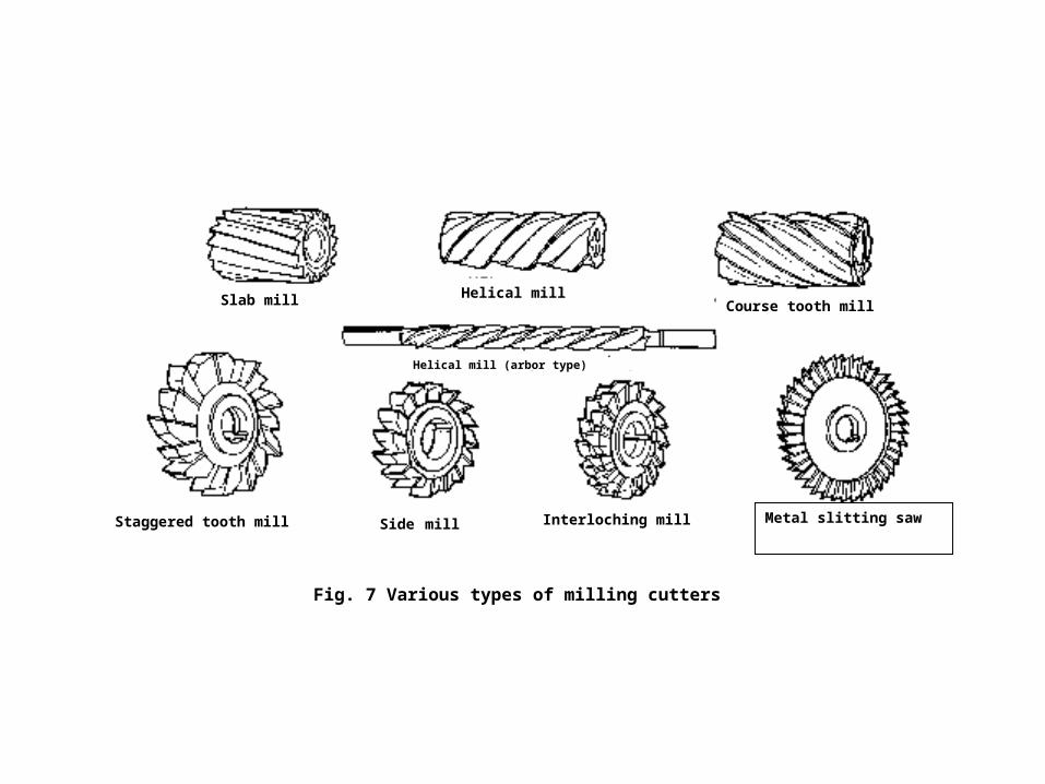
Slab mill Course tooth millHelical mill
Staggered tooth mill Side mill Interloching mill Metal slitting saw
Fig. 7 Various types of milling cutters
Helical mill (arbor type)
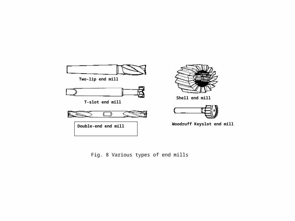
Fig. 8 Various types of end mills
Woodruff Keyslot end millDouble-end end mill
Two-lip end mill
Shell end millT-slot end mill
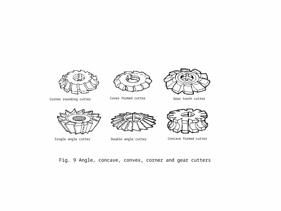
Fig. 9 Angle, concave, convex, corner and gear cutters
Corner rounding cutter Covex formed cutter Gear tooth cutter
Single angle cutter Double angle cutter Concave formed cutter
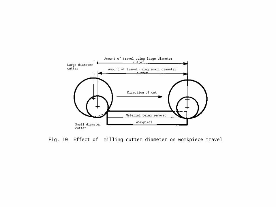
Fig. 10 Effect of milling cutter diameter on workpiece travel
Large diameter cutter
Amount of travel using large diameter cutter
Direction of cut
Material being removed
workpieceSmall diameter cutter
Amount of travel using small diameter cutter
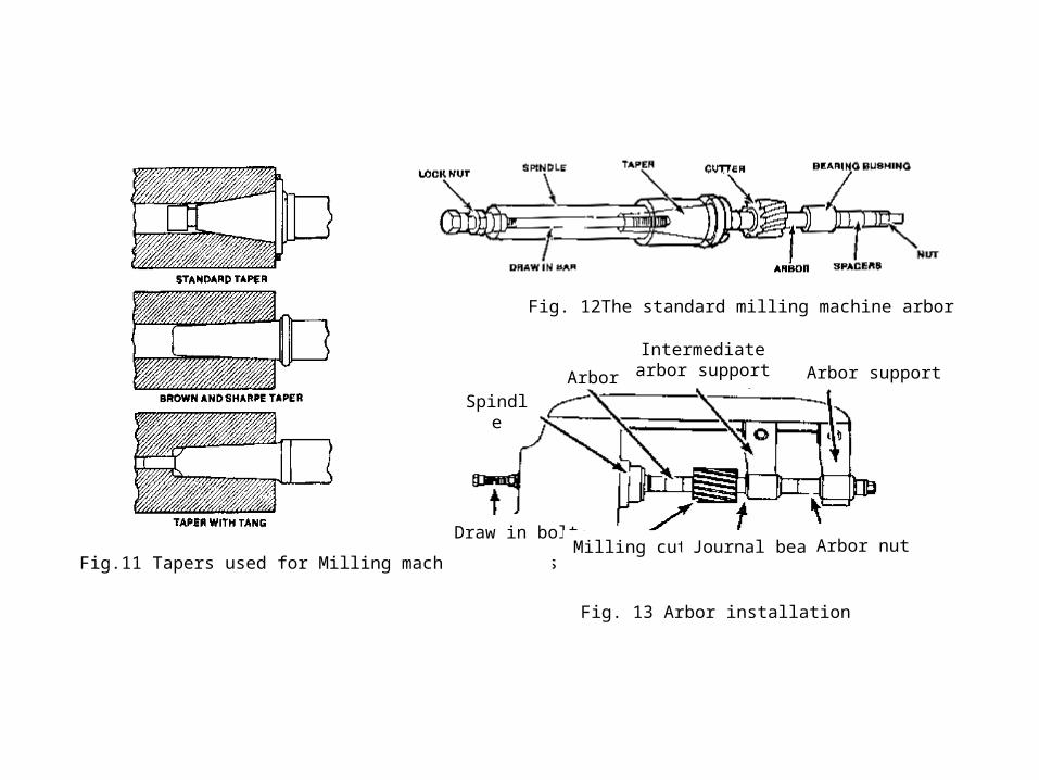
Fig.11 Tapers used for Milling machine arborrs
Fig. 12The standard milling machine arbor
Arbor
Intermediate arbor support Arbor support
Spindle
Draw in boltMilling cutter Journal bearing Arbor nut
Fig. 13 Arbor installation
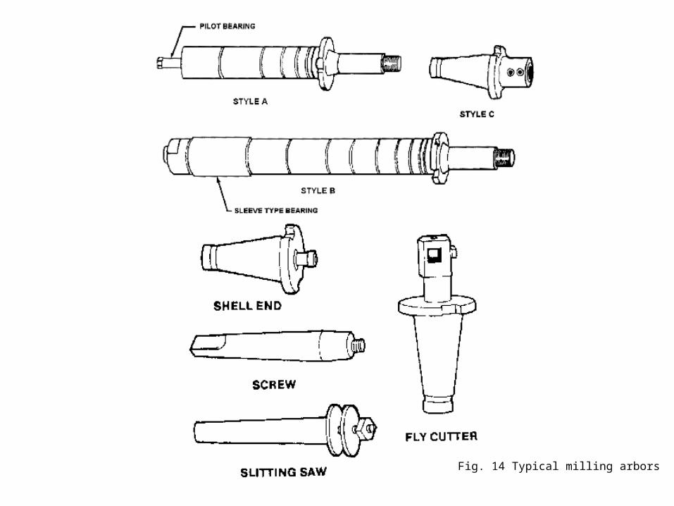
Fig. 14 Typical milling arbors
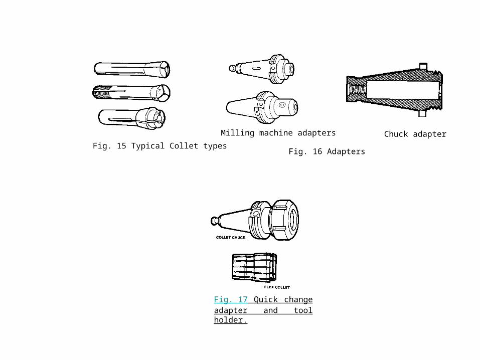
Fig. 15 Typical Collet types
Milling machine adapters Chuck adapter
Fig. 16 Adapters
Fig. 17 Quick change adapter and tool holder.
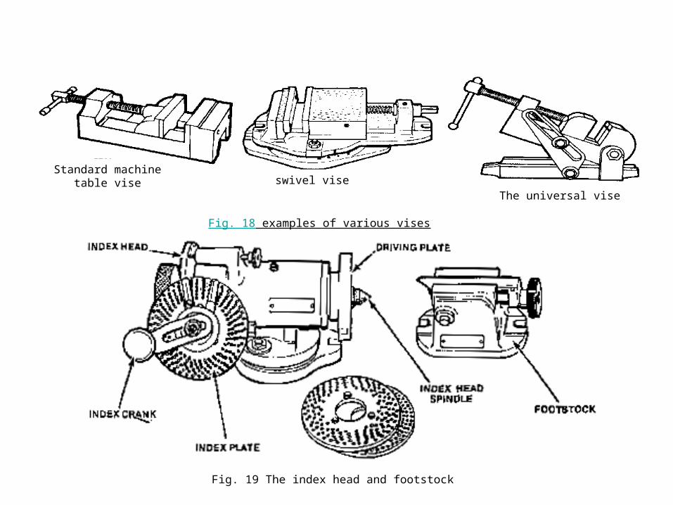
Fig. 18 examples of various vises
swivel viseStandard machine table vise
The universal vise
Fig. 19 The index head and footstock
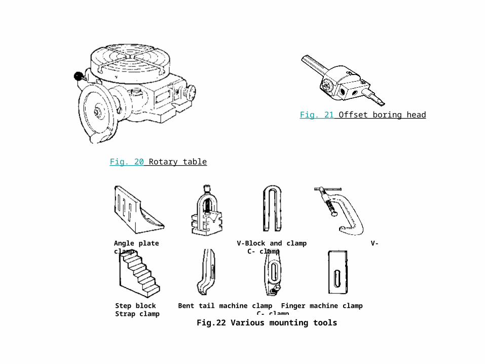
Fig. 20 Rotary table
Fig. 21 Offset boring head
Angle plate V-Block and clamp V-clamp C- clamp
Step block Bent tail machine clamp Finger machine clamp Strap clamp C- clamp
Fig.22 Various mounting tools
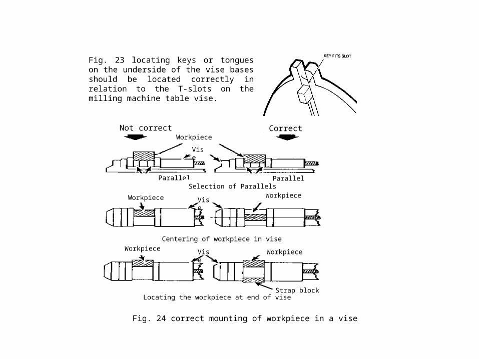
Not correct CorrectWorkpiece
Parallel ParallelSelection of Parallels
Vise
Workpiece Workpiece
Centering of workpiece in vise
Locating the workpiece at end of vise
Fig. 24 correct mounting of workpiece in a vise
Strap block
WorkpieceWorkpiece
Vise
Vise
Fig. 23 locating keys or tongues on the underside of the vise bases should be located correctly in relation to the T-slots on the milling machine table vise.
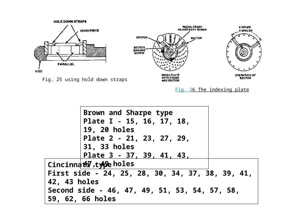
Fig. 25 using hold down straps
Fig. 26 The indexing plate
Brown and Sharpe type Plate I - 15, 16, 17, 18, 19, 20 holes Plate 2 - 21, 23, 27, 29, 31, 33 holes Plate 3 - 37, 39, 41, 43, 47, 49 holes
Cincinnati type First side - 24, 25, 28, 30, 34, 37, 38, 39, 41, 42, 43 holes Second side - 46, 47, 49, 51, 53, 54, 57, 58, 59, 62, 66 holes
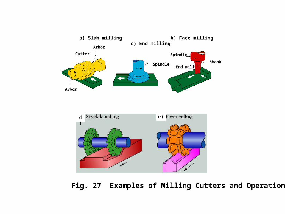
a) Slab milling b) Face milling c) End milling
Arbor
Arbor
Cutter
Spindle
Spindle
Shank End mill
Fig. 27 Examples of Milling Cutters and Operations
d) e)
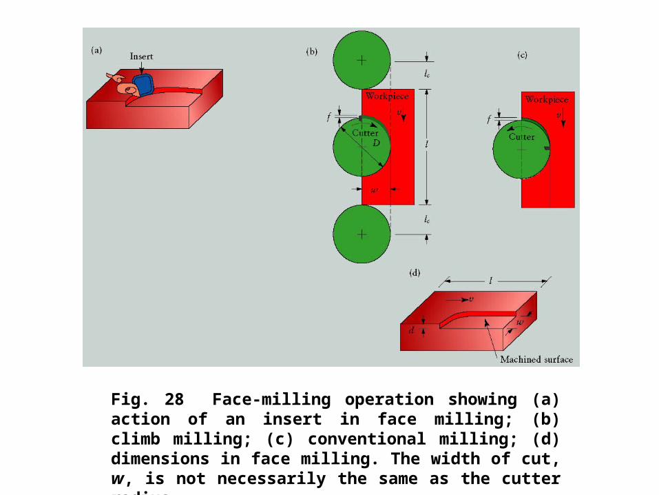
Fig. 28 Face-milling operation showing (a) action of an insert in face milling; (b) climb milling; (c) conventional milling; (d) dimensions in face milling. The width of cut, w, is not necessarily the same as the cutter radius.
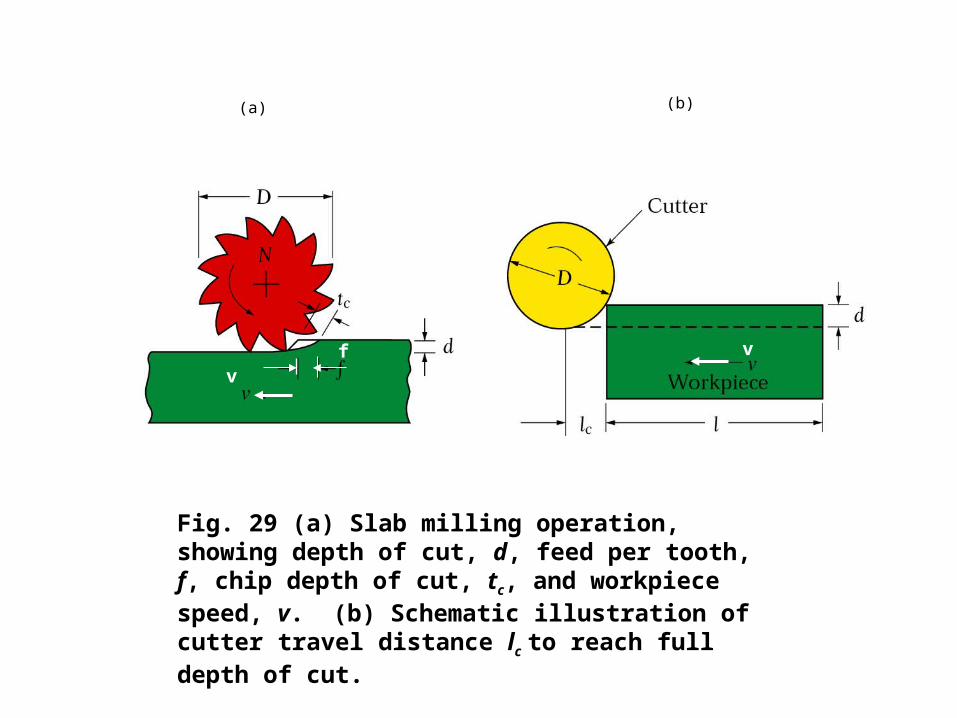
Fig. 29 (a) Slab milling operation, showing depth of cut, d, feed per tooth, f, chip depth of cut, tc, and workpiece speed, v. (b) Schematic illustration of cutter travel distance lc to reach full depth of cut.
f v
v
(a) (b)
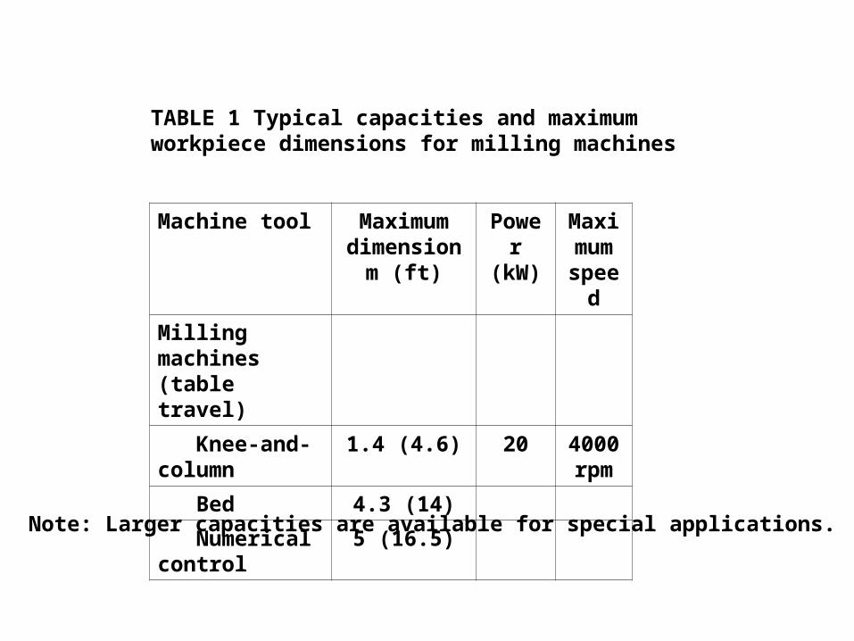
TABLE 1 Typical capacities and maximum workpiece dimensions for milling machines
Machine tool Maximum dimension
m (ft)
Power (kW)
Maximum speed
Milling machines (table travel)
Knee-and-column
1.4 (4.6) 20 4000 rpm
Bed 4.3 (14)
Numerical control
5 (16.5)
Note: Larger capacities are available for special applications.
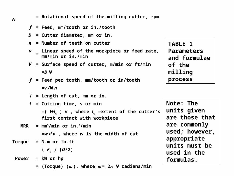
TABLE 1 Parameters and formulae of the milling process
N= Rotational speed of the milling cutter, rpm
f = Feed, mm/tooth or in./tooth
D = Cutter diameter, mm or in.
n = Number of teeth on cutter
v=
Linear speed of the workpiece or feed rate, mm/min or in./min
V = Surface speed of cutter, m/min or ft/min
=D N
f = Feed per tooth, mm/tooth or in/tooth
=v /N n
l = Length of cut, mm or in.
t = Cutting time, s or min
=( l+lc ) v , where lc =extent of the cutter’s first contact with
workpiece
MRR = mm3/min or in.3/min
=w d v , where w is the width of cut
Torque = N-m or lb-ft
( Fc ) (D/2)
Power = kW or hp
= (Torque) ( ), where = 2 N radians/min
Note: The units given are those that are commonly used; however, appropriate units must be used in the formulas.
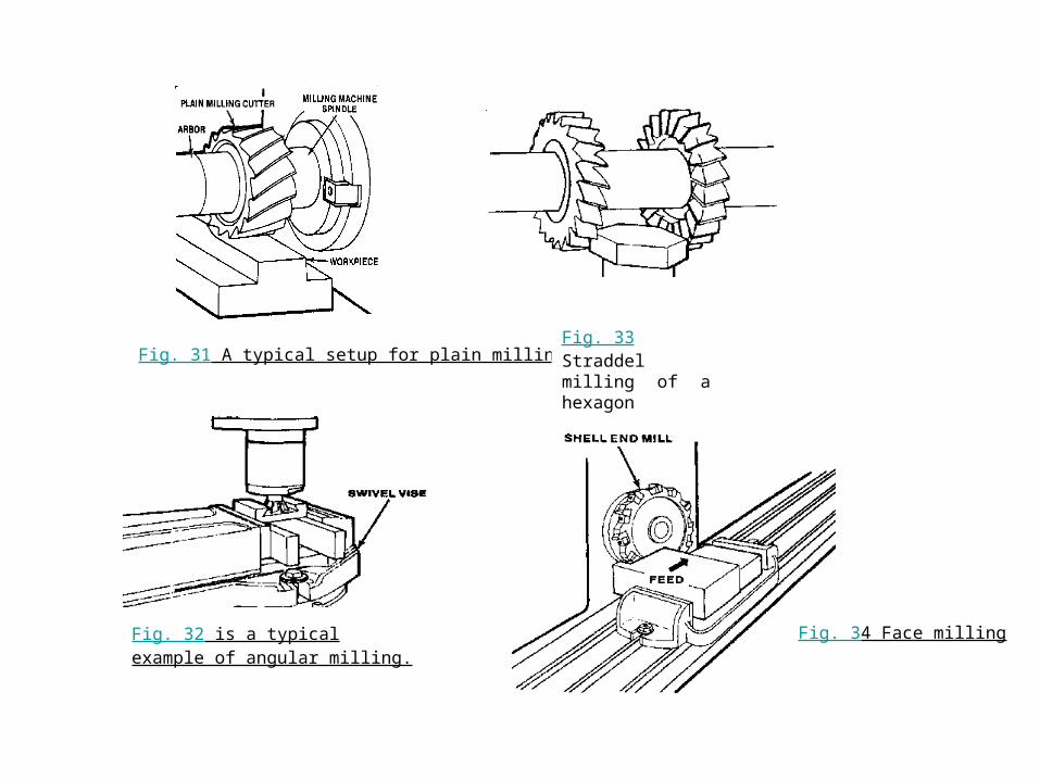
Fig. 31 A typical setup for plain milling
Fig. 32 is a typical example of angular milling.
Fig. 33 Straddel milling of a hexagon
Fig. 34 Face milling
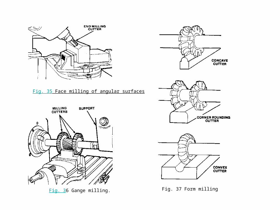
Fig. 35 Face milling of angular surfaces
Fig. 36 Gange milling. Fig. 37 Form milling
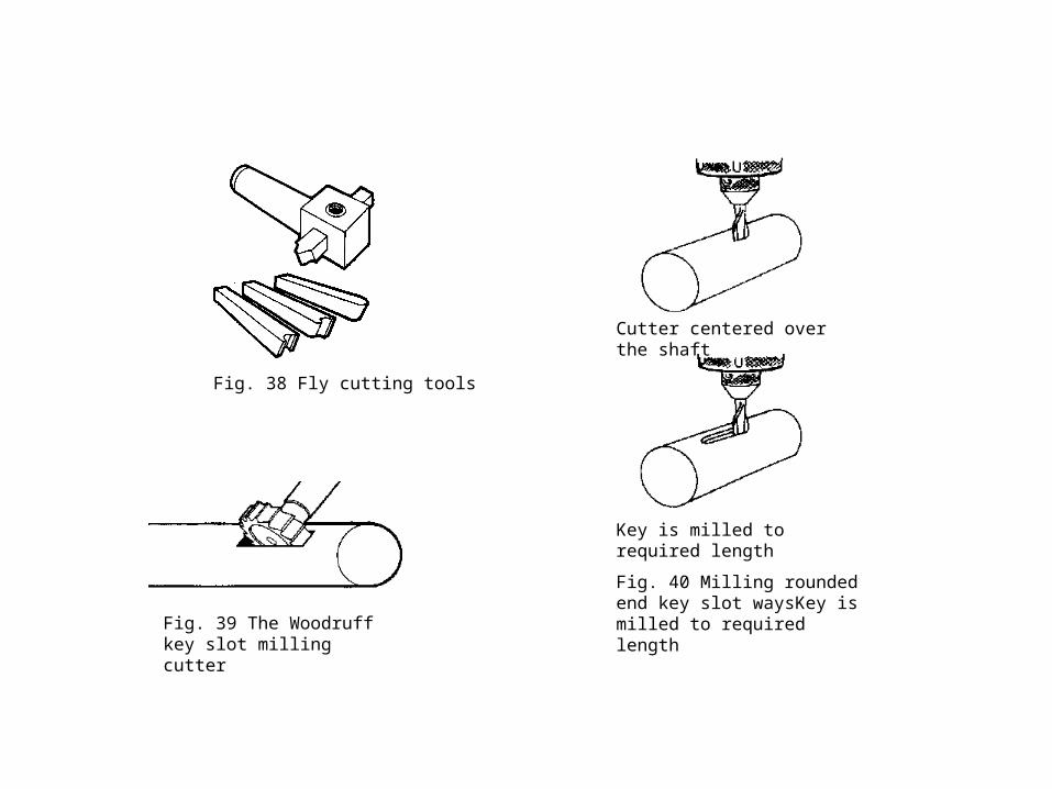
Fig. 38 Fly cutting tools
Fig. 39 The Woodruff key slot milling cutter
Key is milled to required length
Cutter centered over the shaft
Fig. 40 Milling rounded end key slot waysKey is milled to required length
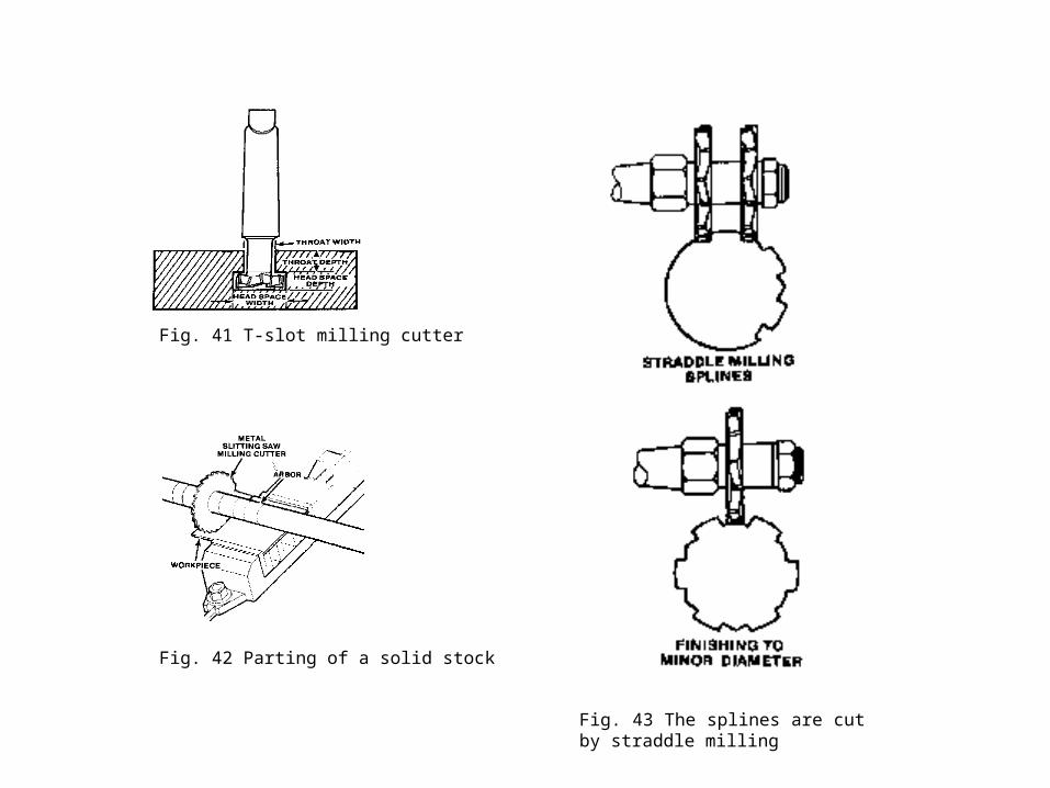
Fig. 41 T-slot milling cutter
Fig. 42 Parting of a solid stock
Fig. 43 The splines are cut by straddle milling