Embed Size (px)
Citation preview
REGISTRO BRASILEIRO Rules for the Construction and Classification of Ships SHIPS IN GENERAL - TITLE 11
DE NAVIOS E AERONAVES Identified by their Missions – Part II NAVAL ARQUITECTURE - SECTION 1 RGMM14EN CHAPTER - A to J and T
RULES 2014 1-1
PART II RULES FOR THE CONSTRUCTION
AND CLASSIFICATION OF
VESSELS IDENTIFIED BY THEIR
MISSIONS
TITLE 11 SHIPS IN GENERAL
SECTION 1 NAVAL ARCHITECTURE
CHAPTERS
A APPROACH
B DOCUMENTS, REGULATIONS AND
STANDARDS
C NAVIGATION ENVIRONMENT
D ACTIVITES / SERVICES
E CONFIGURATIONS
F DIMENSIONS AND HULL LINES
G CAPACITIES AND SUBDIVISION
H LOADING CONDITIONS, STABILITY AND
BUOYANCY
I PROPULSION PERFORMANCE
J ON-BOARD COMPUTERS FOR STABILITY
CALCULATIONS
T INSPECTIONS AND TESTS

REGISTRO BRASILEIRO Rules for the Construction and Classification of Ships SHIPS IN GENERAL - TITLE 11
DE NAVIOS E AERONAVES Identified by their Missions – Part II NAVAL ARQUITECTURE - SECTION 1 RGMM14EN CHAPTER - A to J and T
1-2 RULES 2014

REGISTRO BRASILEIRO Rules for the Construction and Classification of Ships SHIPS IN GENERAL - TITLE 11
DE NAVIOS E AERONAVES Identified by their Missions – Part II NAVAL ARQUITECTURE - SECTION 1 RGMM14EN CHAPTER - A to J and T
RULES 2014 1-3
CONTENTS
CHAPTER A ......................................................................5
APPROACH ......................................................................5
A1. APPROACH.......................................................5 100. Application ......................................................5
A2. DEFINITIONS ...................................................5 100. Terms ...............................................................5
CHAPTER B .................................................................... 10
DOCUMENTS, REGULATIONS AND STANDARDS
........................................................................................... 10
B1. NAVAL ARCHITECTURE STANDARDS ... 10 100. Documents for classification ......................... 10 200. Statutory documents for approval.................. 10 300. Construction documents ................................ 10
B2 REGULATION ................................................ 10 100. Regulations of the National Administration .. 10 200. Emissions of other National Administrations 10 300. International regulation................................. 10 400. IACS requirements ......................................... 11
B3. TECHNICAL STANDARDS .......................... 11 100. Industrial Standards ...................................... 11
CHAPTER C .................................................................... 11
NAVIGATION ENVIRONMENT ................................. 11
C1. NAVIGATION ZONES................................... 11 100. Scope.............................................................. 11
C2. SHIP MOVEMENTS ...................................... 11 100. Induced forces................................................ 11 200. Symbols used in Subchapter C2 ..................... 12 300. Ship’s motions and accelerations: General ... 14 400. Ship absolute motions and accelerations ....... 15 500. Ship relative accelerations ........................... 15
C3. ENVIRONMENT PRESERVATION ............ 16 100. Compliance to Environmental Regulations ... 16
CHAPTER D .................................................................... 16
ACTIVITIES AND SERVICES ..................................... 16
D1. TYPES OF ACTIVITIES AND SERVICES .. 16 100. Types of vessels in the present Rules ............. 16 200. Statutory surveys ............................................ 16
D2. OPERATION AND MAINTENANCE OF
SHIPS 17 100. Adequate crew ............................................... 17
CHAPTER E .................................................................... 17
CONFIGURATIONS ...................................................... 17
E1. HULL COMPATIBILITY .............................. 17 100. Sailing characteristics ................................... 17 200. Navigation aids .............................................. 17
E2. BASIC GENERAL ARRANGEMENT .......... 17 100. Location of cargo spaces ............................... 17 200. Engine Room location.................................... 17 300. Accommodation location ............................... 17
CHAPTER F .................................................................... 18
HULL SHAPE AND DIMENSIONS ............................. 18
F1. DIMENSIONS ................................................. 18 100. Hull dimensions and proportions .................. 18
F2. HULL FORMS ................................................ 18 100. Focus on hull shape ...................................... 18
CHAPTER G ................................................................... 18
SUBDIVISION ................................................................ 18
G1. CAPACITIES .................................................. 18 100. Volumes and volume centres ......................... 18
G2. HULL SUBDIVISION .................................... 18 100. Compartments, tanks and empty spaces ....... 18 200. Cofferdams .................................................... 18
CHAPTER H ................................................................... 19
LOADING CONDITIONS, BUOYANCY AND
STABILITY .................................................................... 19
H1. LOAD LINE .................................................... 19 100. Load line assignment .................................... 19
H2. LIGHT SHIP WEIGHT ................................. 19 100. Determination of the light ship weight .......... 19
H3. LOADING CONDITIONS ............................. 19 H4. BUOYANCY AND SUBDIVISION OF THE
HULL 19 100. Principles ...................................................... 19 200. Subdivision bulkheads to contain flooding ... 19 300. Vertical subdivision ...................................... 20 400. Hull openings and means of closure ............. 20 500. Angle of flooding ........................................... 21 600. Minimizing the flooding effects ..................... 21 700. Minimizing the free surface effect ................. 21
H5. INTACT STABILITY .................................... 21 100. Intact Stability ............................................... 21 200. Conditions of loading .................................... 22 300. Weight distribution ....................................... 23 400. Free surface .................................................. 23 500. Stability booklet ............................................ 26 600. Permanent ballast ......................................... 27
H6. DAMAGED STABILITY ............................... 27 100. Subdivision and Damage D Stability ............ 27
CHAPTER I .................................................................... 27
PROPULSION PERFORMANCE ................................ 27
I1. PROPULSION PERFORMANCE ................ 27 100. Selection of the propulsion system ................ 27
I2. HIGH SPEED CRAFT ................................... 27 100. Definition ...................................................... 27 200. Special approach .......................................... 28
CHAPTER J .................................................................... 28
ON-BOARD COMPUTERS FOR STABILITY
CALCULATIONS .......................................................... 28
J1. APPLICATION .............................................. 28 100. Application .................................................... 28
J2. GENERAL PRINCIPLES .............................. 28 100. General Principles .................................... 28
J3. CALCULATION SYSTEMS IACS UR L5.2 29 100. General ......................................................... 29 200. Types of Stability Software IACS UR L5.3 .... 29
J4. FUNCTIONAL REQUIREMENTS .............. 29 100. Required data ................................................ 29 200. Acceptable Tolerances IACS UR L5.5 .......... 29
J5. APPROVAL PROCEDURES ........................ 30

REGISTRO BRASILEIRO Rules for the Construction and Classification of Ships SHIPS IN GENERAL - TITLE 11
DE NAVIOS E AERONAVES Identified by their Missions – Part II NAVAL ARQUITECTURE - SECTION 1 RGMM14EN CHAPTER - A to J and T
1-4 RULES 2014
100. Conditions of approval of the onboard
software for stability calculations ............................. 30 200. General Approval (optional) IACS UR L5.6.1
30 300. Specific approval........................................... 31
J6. OPERATION MANUAL ................................ 31 100. Operation Manual ......................................... 31
J7. REQUIREMENTS FOR LOADING
CONDITIONS, LOADING MANUALS AND
LOADING INSTRUMENTS ..................................... 31 100. General ........................................................ 32 200. Application ................................................... 32 300. Definitions ..................................................... 32 400. Annual and Special Survey ........................... 32 500. Loading Conditions, Loading Manuals and
Loading Instruments ................................................. 32 600. Conditions of Approval of Loading Manuals 32
CHAPTER T ................................................................... 32
INSPECTIONS AND TESTS FOR NAVAL
ACRHITECTURE .......................................................... 32
T1. TESTS DURING CONTRUCTION .............. 33 100. Dfrat marks measument ................................ 33
T2. TESTS AT THE COMPLETION OF
BUILDING .................................................................. 33 100. Inclining experiment ..................................... 33 200. Deadweight Measurement (“draft survey”).. 33 300. Tolerances for vessels ................................... 33
T3. SEA TRIALS ................................................... 33 100. Propulsion and manoeuvring performance ... 33
T4. INSTALLATION TESTING FOR ON-
BOARD COMPUTERS FOR STABILITY
CALCULATIONS ...................................................... 34 100. Installation Testing ....................................... 34 200. Periodical Testing ......................................... 34
T5. IACS GUIDELINES AND
RECOMMENDATIONS FOR INCLINING
EXPERIMENT ........................................................... 35 100. General Preparation for the Test .................. 35 200. The inclining test condition ........................... 35 300. Inclining Weights, pendulum and instruments
36 400. Trim and Stability.......................................... 37 500. Draught and Water Density Measurements .. 37 600. Weight shifts and Inclination Measurements. 37 700. Other Relevant Data ..................................... 39 800. Test Report and Analysis of Lightship Data .. 39

REGISTRO BRASILEIRO Rules for the Construction and Classification of Ships SHIPS IN GENERAL - TITLE 11
DE NAVIOS E AERONAVES Identified by their Missions – Part II NAVAL ARQUITECTURE - SECTION 1 RGMM14EN CHAPTER - A to J and T
RULES 2014 1-5
CHAPTER A
APPROACH
CHAPTER CONTENTS
A1. APPROACH
A2. DEFINITIONS
A1. APPROACH
100. Application
101. The present Part II, Title 11, Section 1 is applicable
to all vessels.
102. The load line requirements for vessels under 500 GT
or having GT equal to or greater than 500 are given in the
application of each Chapter.
A2. DEFINITIONS
100. Terms
101. 2008 IS Code means the International Code on
Intact Stability, 2008, consisting of an introduction, part A
(the provisions of which shall be treated as mandatory) and
part B (the provisions of which shall be treated as
recommendatory), as adopted by resolution MSC.267(85),
provided that:
a. amendments to the introduction and part A of the
Code are adopted, brought into force and take effect
in accordance with the provisions of article VIII of
the SOLAS Convention concerning the amendment
procedures applicable to the Annex other than
chapter I thereof; and
b. amendments to part B of the Code are adopted by
the Maritime Safety Committee in accordance with
its Rules of Procedure.
102. Amidship: distance centred at half of the length L,
with extension of de 0,4 L.
103. Pontoon: Vessel type A (see definition above)
without self propulsion, with or without a trunk deck.
104. Barge: B-type vessel or closed deck vessel for cargo
on deck without self propulsion, with or without double
shell or double bottom, which meets the following
relations, according to the NORMAN:
a. Breadth / draft> 6
b. Breadth / depth> 3.
105. Bilge system: piping system designed to pump out
the flooding and/or bilge water from the ship’s
compartments.
106. IACS UR S2.2 Block coefficient Cb the block
coefficient Cb is the moulded block coefficient at draught d
corresponding to summer load waterline, based on rule
length L and moulded breadth B:
Cb = Δ * d/ (L*B*d) where:
Cb is the moulded block coefficient at draught d
corresponding to summer load waterline, based on rules
length Land moulded breadth B
Δ = Moulded Displacement (m3) is the moulded
displacement of the vessel in cubic metes, excluding
appendages, taken at the summer load line (draught d)
L = length of L is the distance, in metres, on the summer
load waterline from the fore side of the stem to the after
side of the rudder post, or the centre of the rudder stock if
there is no rudder post. L is not to be less than 96%, and
need not be greater than 97%, of the extreme length on the
summer load waterline. In ships with unusual stern and
bow arrangement the length L will be specially
considered.(ILL Reg 3)
B is the breadth of the vessel as defined below.
d is the vessel's draught at the summer load load line.
107. Breadth B: largest moulded breadth of the ship
measured at the broadest transverse section of the hull, in
meters.
108. Closed deck: ship with strong deck all along the
length and breadth to carry load on the deck or liquid
cargoes inside the hull, with or without a trunk.
109. Common watertight bulkhead (AEC): bulkhead
of watertight construction built as part of the hull structure
for purpose of subdivision of the hull into watertight
compartments, restricting the effect of flooding. See Part II,
Title 11, Section 2 of the Rules.
110. Deckhouse: construction other than a
superstructure, located on the freeboard deck or above,
which does not fit as a superstructure with deck.
111. Design pressure: means the hydrostatic pressure for
which each structure or appliance assumed to be watertight
in the intact and damage stability calculations is designed to
withstand.
112. Freeboard Deck (according to ILLC): the freeboard
deck is the uppermost complete deck exposed to weather
and sea, which has permanent means of closing all
openings in the weather part thereof, and below which all
openings in the sides of the ship are fitted with permanent
means of watertight closing.
REGISTRO BRASILEIRO Rules for the Construction and Classification of Ships SHIPS IN GENERAL - TITLE 11
DE NAVIOS E AERONAVES Identified by their Missions – Part II NAVAL ARQUITECTURE - SECTION 1 RGMM14EN CHAPTER - A to J and T
1-6 RULES 2014
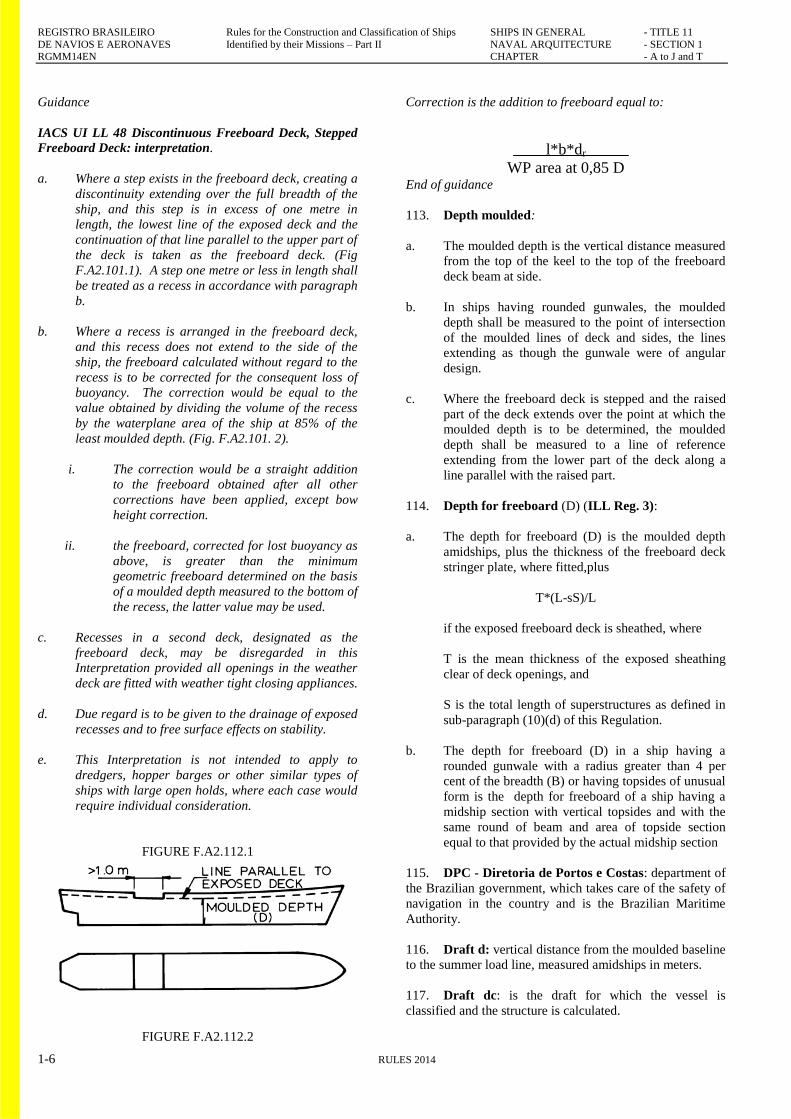
Guidance
IACS UI LL 48 Discontinuous Freeboard Deck, Stepped
Freeboard Deck: interpretation.
a. Where a step exists in the freeboard deck, creating a
discontinuity extending over the full breadth of the
ship, and this step is in excess of one metre in
length, the lowest line of the exposed deck and the
continuation of that line parallel to the upper part of
the deck is taken as the freeboard deck. (Fig
F.A2.101.1). A step one metre or less in length shall
be treated as a recess in accordance with paragraph
b.
b. Where a recess is arranged in the freeboard deck,
and this recess does not extend to the side of the
ship, the freeboard calculated without regard to the
recess is to be corrected for the consequent loss of
buoyancy. The correction would be equal to the
value obtained by dividing the volume of the recess
by the waterplane area of the ship at 85% of the
least moulded depth. (Fig. F.A2.101. 2).
i. The correction would be a straight addition
to the freeboard obtained after all other
corrections have been applied, except bow
height correction.
ii. the freeboard, corrected for lost buoyancy as
above, is greater than the minimum
geometric freeboard determined on the basis
of a moulded depth measured to the bottom of
the recess, the latter value may be used.
c. Recesses in a second deck, designated as the
freeboard deck, may be disregarded in this
Interpretation provided all openings in the weather
deck are fitted with weather tight closing appliances.
d. Due regard is to be given to the drainage of exposed
recesses and to free surface effects on stability.
e. This Interpretation is not intended to apply to
dredgers, hopper barges or other similar types of
ships with large open holds, where each case would
require individual consideration.
FIGURE F.A2.112.1
FIGURE F.A2.112.2
Correction is the addition to freeboard equal to:
l*b*dr
WP area at 0,85 D End of guidance
113. Depth moulded:
a. The moulded depth is the vertical distance measured
from the top of the keel to the top of the freeboard
deck beam at side.
b. In ships having rounded gunwales, the moulded
depth shall be measured to the point of intersection
of the moulded lines of deck and sides, the lines
extending as though the gunwale were of angular
design.
c. Where the freeboard deck is stepped and the raised
part of the deck extends over the point at which the
moulded depth is to be determined, the moulded
depth shall be measured to a line of reference
extending from the lower part of the deck along a
line parallel with the raised part.
114. Depth for freeboard (D) (ILL Reg. 3):
a. The depth for freeboard (D) is the moulded depth
amidships, plus the thickness of the freeboard deck
stringer plate, where fitted,plus
T*(L-sS)/L
if the exposed freeboard deck is sheathed, where
T is the mean thickness of the exposed sheathing
clear of deck openings, and
S is the total length of superstructures as defined in
sub-paragraph (10)(d) of this Regulation.
b. The depth for freeboard (D) in a ship having a
rounded gunwale with a radius greater than 4 per
cent of the breadth (B) or having topsides of unusual
form is the depth for freeboard of a ship having a
midship section with vertical topsides and with the
same round of beam and area of topside section
equal to that provided by the actual midship section
115. DPC - Diretoria de Portos e Costas: department of
the Brazilian government, which takes care of the safety of
navigation in the country and is the Brazilian Maritime
Authority.
116. Draft d: vertical distance from the moulded baseline
to the summer load line, measured amidships in meters.
117. Draft dc: is the draft for which the vessel is
classified and the structure is calculated.

REGISTRO BRASILEIRO Rules for the Construction and Classification of Ships SHIPS IN GENERAL - TITLE 11
DE NAVIOS E AERONAVES Identified by their Missions – Part II NAVAL ARQUITECTURE - SECTION 1 RGMM14EN CHAPTER - A to J and T
RULES 2014 1-7
118. Draft dP: is the draft for which the vessel is
designed. Note that when the keel is inclined the actual aft
draft may have a greater value than by the definition.
119. Draft (ds) Deepest subdivision draft is the waterline
which corresponds to the summer load line draught of the
ship.
120. DVC: Distance of visibility of the coast is defined
in NORMAM 01, Chapter 6 defines (the area of coastal
navigation).
121. Fast ships: see the relevant Title.
122. "Ferry boat": vessel designed for the transportation
of vehicles and passengers in crossings of rivers, channels,
estuaries, bays or in coastal short crossings.
123. Forward and aft ends: distance of 0,1× L,
measured from teach one of the forward and aft
perpendiculars.
124. Freeboard: distance prescribed in ILLC and
NORMAN 01, measured vertically downwards amidships
from the upper edge of the deck line to the upper edge of
the related load line which determines the maximum draft
water line. It is marked on the side shell, at the middle of
the length Lf, by a circle with a horizontal line in the
middle. See. Part II, Title 11, Chapter H, conditions of
loading.
125. Freeboard Deck (according to ILLC): the freeboard
deck is normally the uppermost complete deck exposed to
weather and sea, which has permanent means of closing all
openings in the weather part thereof, and below which all
openings in the sides of the ship are fitted with permanent
means of watertight closing.
a. In a ship having a discontinuous freeboard deck, the
lowest line of the exposed deck and the continuation
of that line parallel to the upper part of the deck is
taken as the freeboard deck.
b. At the option of the owner and subject to the
approval of the Administration, a lower deck may be
designated as the freeboard deck provided it is a
complete and permanent deck continuous in a fore
and aft direction at least between the machinery
space and peak bulkheads and continuous
athwartships.
c. When this lower deck is stepped the lowest line of
the deck and the continuation of that line parallel to
the upper part of the deck is taken as the freeboard
deck.
d. When a lower deck is designated as the freeboard
deck, that part of the hull which extends above the
freeboard deck is treated as a superstructure so far as
concerns the application of the conditions of
assignment and the calculation of freeboard. It is
from this deck that the freeboard is calculated.
126. Freeboard Length LBL The length (L) shall be
taken as 96% of the total length on a waterline at 85% of
the least moulded depth measured from the top of the keel,
or as the length from the fore-side of the stem to the axis of
the rudder stock on that waterline, if that be greater. Where
the stem contour is concave above the waterline at 85% of
the least moulded depth, both the forward terminal of the
total length and the fore-side of the stem respectively shall
be taken at the vertical projection to that waterline of the
after most point of the stem contour (above that waterline).
In ships designed with a rake of keel the waterline on which
this length is measured shall be parallel to the designed
waterline.See figure F.A2.126.1
127. Inclining test: The inclining test is a procedure
which involves moving a series of known weights,
normally in the transverse direction, and then measuring the
resulting change in the equilibrium heel angle of the ship.
By using this information and applying basic naval
architecture principles, the ship's vertical centre of gravity
(VCG or KG) is determined.
128. “ILLC”: IMO “International Load Line
Convention‖
129. Lightship: The lightship is a ship complete in all
respects, but with-out consumables, stores, cargo, and crew
and effects, and without any liquids on board except for
machinery and piping fluids, such as lubricants and
hydraulics, which are at operating levels.
130. Lightweight check: The lightweight check is a
procedure which involves auditing all items which are to be
added, deducted or relocated on the ship at the time of the
inclining test so that the observed condition of the ship can
be adjusted to the lightship condition. The weight and
longitudinal, transverse and vertical location of each item
are to be accurately determined and recorded. The lightship
dis-placement and longitudinal centre of gravity (LCG) can
be obtained using this information, as well as the static
waterline of the ship at the time of the inclining test as
determined by measuring the freeboard or verified draught
marks of the ship, the ship's hydrostatic data and the sea
water density.
FIGRE F.A2.126.1

REGISTRO BRASILEIRO Rules for the Construction and Classification of Ships SHIPS IN GENERAL - TITLE 11
DE NAVIOS E AERONAVES Identified by their Missions – Part II NAVAL ARQUITECTURE - SECTION 1 RGMM14EN CHAPTER - A to J and T
1-8 RULES 2014
131. Machinery spaces: spaces of category A and other
spaces containing:
a. propulsion machinery, boilers, oil fuel units, steam
and internal combustion engines;
b. generators and major electrical equipment;
c. oil filling stations;
d. refrigeration , stabilizing, ventilation and air
conditioning equipment; and
e. similar spaces and their trunks.
132. Machinery spaces of category A: are those spaces
and trunks to such spaces which contain either:
a. internal combustion machinery used for main
propulsion;
b. internal combustion machinery used for purposes
other than main propulsion where such machinery
has in the aggregate a total power output of not less
than 375 kW; or
c. any oil-fired boiler or oil fuel unit, or any oil-fired
equipment other than boilers, such as inert gas
generators, incinerators, etc.
133. Main Deck: continuous deck from which the is
measured the Freeboard and on which stand the
superstructures
134. Moulded depth:
a. The moulded depth is the vertical distance measured
from the top of the keel to the top of the freeboard
deck beam at side. In wood and composite ships the
distance is measured from the lower edge of the keel
rabbet. Where the form at the lower part of the
midship section is of a hollow character, or where
thick garboards are fitted, the distance is measured
from the point where the line of the flat of the
bottom continued inwards cuts the side of the keel.
b. In ships having rounded gunwales, the moulded
depth shall be measured to the point of intersection
of the moulded lines of deck and sides, the lines
extending as though the gunwale were of angular
design.
c. Where the freeboard deck is stepped and the raised
part of the deck extends over the point at which the
moulded depth is to be determined, the moulded
depth shall be measured to a line of reference
extending from the lower part of the deck along a
line parallel with the raised part.
135. Navigation zone: area defined in accordance with
the environmental conditions of navigation. See NORMAM
01 chapter 2 and Part I, Title 1, Section 01 of the present
Rules.
136. Open deck: resistant open deck (with or without
hatch cover or similar)
137. Open sea: areas of sea and ocean navigation
according to NORMAM 01 Chapter 2.
138. O1, O2: areas of sea and ocean navigation as
defined in Part I, Title 1, Section 1 of the present Rules,
where O1 is defined as coastal navigation (DVC) and O2 is
defined as ocean navigation.
139. MARPOL: IMO ―International Convention for the
Prevention of Pollution from Ships".
140. Perpendiculars: vertical lines at the extremities and
in the diddle of the length L, named ―forward
perpendicular‖ and ―aft perpendicular‖.
141. Perpendicular amidships: vertical line at the end
of length L.
142. Aft perpendicular: vertical line at the aft end of
length L.
143. Forward perpendicular: vertical line at the
forward end of length L.
Guidance
ILL Regulation 3: Perpendiculars. The forward and after
perpendiculars shall be taken at the forward and after ends
of the length (L). The forward perpendicular shall coincide
with the foreside of the stem on the waterline on which the
length is measured.
End of guidance
144. Permeability (μ) of a space is the proportion of the
immersed volume of that space which can be occupied by
water.
Guidance [IACS UI SC 225]
IACS Unified Interpretation SC 225(Sept 2008)
The occupied volume by flooded water of a flooded space in
the SOLAS Chapter II-1(Regulation 2(14)) also issued as
SOLAS Interpretations as approved by IMO 01-06-2010
(Technical background excepted) Interpretation
In determining the permeability of a space, the volume of a
space is to be taken as the moulded volume, i.e. the
immersed volume of a space shall be the underwater
moulded volume of that space multiplied by the
permeability.
Technical Background for this IACS UI Sept 2008):
With regard to whether net capacity (i.e. capacity with
reduction of volume of inside structural members) or

REGISTRO BRASILEIRO Rules for the Construction and Classification of Ships SHIPS IN GENERAL - TITLE 11
DE NAVIOS E AERONAVES Identified by their Missions – Part II NAVAL ARQUITECTURE - SECTION 1 RGMM14EN CHAPTER - A to J and T
RULES 2014 1-9
moulded capacity shall be used to determine the volume of
flooded water in the damage stability calculation under
Regulation 2(14) (the definition of permeability) of SOLAS
II-1 as contained in resolution MSC.194(80), IACS
members reached the agreement that moulded capacity
shall be the basis for calculating the flooded water volume,
i.e., the immersed volume of a space shall be the
underwater moulded volume of that space multiplied by the
permeability. In order to uniformly implement the inherent
requirement of the definition of permeability, a UI has been
developed to give a common ground on this issue.
Identical interpretations have been set out in
MSC.1/Circ.1362 of 2010-05-26, Unified interpretation of
SOLAS Chapter II-1.
End of guidance
145. Positions 1 and 2 for vessels with GT ≥ 500: For
the purpose of The present Rules, two positions of
hatchways, doorways and ventilators are defined as
follows:
a. Position 1 - Upon exposed freeboard and raised
quarter decks, and upon exposed superstructure
decks situated forward of a point located a quarter of
the ship' s length from the forward perpendicular.
b. Position 2 - Upon exposed superstructure decks
situated abaft a quarter of the ship' s length from the
forward perpendicular and located at least one
standard height of superstructure above the
freeboard deck.
c. Upon exposed superstructure decks situated forward
of a point located a quarter of the ship' s length from
the forward perpendicular and located at least two
standard heights of superstructure above the
freeboard deck.
146. Rules: for application in all Chapters, Rules means
henceforth the classification and technical standards issued
by the RBNA, i.e., Rules for the Construction and
Classification of Sea Going Vessels.
147. Regulations: laws, regulations, circulars, etc issued
by the official National or International Organizations
which contain their specific set of requirements and
procedures.
148. IACS UR S2 Scantling Length L: horizontal distance
in meters, parallel to the design line of flotation, measured
at the waterline corresponding to the maximum draft, from
the meeting point of this line with the outer face of the
stem, which determines the forward perpendicular, to the
external face of rudder stem or until the centre of the rudder
stock, which determines the aft perpendicular and shall not
be less than 96% nor needing to be greater than 97% of the
length of the waterline. In the event of vessels without
rudder stock the same applies as to the length of the
flotation line. In the case of ferry and barge this value is
adopted as the length between the transoms.
149. SOLAS: IMO ―International Convention for the
Safety of Life At Sea‖.
149. Subdivision length (Ls) of the ship is the greatest
projected moulded length of that part of the ship at or
below deck or decks limiting the vertical extent of flooding
with the ship at the deepest subdivision draught.
150. Superstructure: a superstructure is a decked
structure on the freeboard deck, extending from side to side
of the ship or with the side plating not being inboard of the
shell plating more than 4% of the breadth (B).
a. Enclosed superstructure is a superstructure with:
a.1. enclosing bulkheads of efficient construction;
a.2. access openings, if any, in these bulkheads fitted
with doors complying with the requirements of
regulation 12 of the ILLC – International Load Line
Convention, Annex 1, and NORMAM 01.chapter
07.
a.3. all other openings in sides or ends of the
superstructure fitted with efficient weather tight
means of closing.
a.4. a bridge or poop shall not be regarded as enclosed
unless access is provided for the crew starting from
any point on the uppermost complete exposed deck
or higher to reach machinery and other working
spaces inside these superstructures by alternative
means which are available at all times when
bulkhead openings are closed. [IACS UI LL3]
b. Bridge. A bridge is a superstructure which does not
extend to either the forward or after perpendicular.
c. Poop. A poop is a superstructure which extends
from the after perpendicular forward to a point
which is aft of the forward perpendicular. The poop
may originate from a point aft of the aft
perpendicular.
d. Forecastle. A forecastle is a superstructure which
extends from the forward perpendicular aft to a point
which is forward of the after perpendicular. The
forecastle may originate from a point forward of the
forward perpendicular.
e. Full superstructure. A full superstructure is a
superstructure which, as a minimum, extends from
the forward to the after perpendicular.
f. Raised quarterdeck. A raised quarterdeck is a
superstructure which extends forward from the after
perpendicular, generally has a height less than a
normal superstructure, and has an intact front
bulkhead (sides cuttles of the non-opening type
fitted with efficient deadlights and bolted man hole
covers). Where the forward bulkhead is not intact

REGISTRO BRASILEIRO Rules for the Construction and Classification of Ships SHIPS IN GENERAL - TITLE 11
DE NAVIOS E AERONAVES Identified by their Missions – Part II NAVAL ARQUITECTURE - SECTION 1 RGMM14EN CHAPTER - A to J and T
1-10 RULES 2014
due to doors and access openings, the superstructure
is then to be considered as a poop.
151. Superstructure deck. A superstructure deck is a
deck forming the upper boundary of a superstructure.
152. Tank bulkhead (ATQ): bulkhead of watertight
construction built as part of the structure or not, for the
purpose of delimiting tanks continuously subjected to
hydrostatic pressure. See Part II, Title 11, Section 2 of the
Rules.
153. Weathertight means that in any sea conditions
water will not penetrate into the ship.
157. Watertight means having scantlings and
arrangements capable of preventing the passage of water in
any direction under the head of water likely to occur in
intact and damaged conditions. In the damaged condition,
the head of water is to be considered in the worst situation
at equilibrium, including intermediate stages of flooding.
CHAPTER B
DOCUMENTS, REGULATIONS AND STANDARDS
CHAPTER CONTENTS
B1. NAVAL ARCHITECTURE DOCUMENTS
B2. REGULATIONS
B3. TECHNICAL STANDARDS
B1. NAVAL ARCHITECTURE STANDARDS
100. Documents for classification
101. The plans or documents to be submitted to the
Society for approval or for information are listed in item
B1.200 below under IACS UR L2 ―Stability – a matter of
Class‖.
200. Statutory documents for approval
201. The plans required by the National Regulations are
to be submitted to the RBNA for approval. Such plans may
include:
a. General Arrangement
b. Lines Plan
c. Capacity Plan
d. Hydrostatic and Isocline Curves or Tables
e. Loading Manual, where required.
f. Loading and unloading arrangement to be included
in the ILO Register
g. Cargo securing manual, where required.
h. Tonnage calculation notes;
i. Inclining experiment report;
j. Deadweight and draft experiment (when the
inclination experiment can be substituted);
k. Stability and Trim booklet (for the several
conditions of loading); and
l. Load line calculations.
300. Construction documents
301. The construction documents are to be part of the
ship’s files to be assembled during construction and to be
submitted to the surveyor. Those documents are part of
RBNA final report for new buildings. See Part I, Title 01,
Section 2, C5.700.
B2 REGULATION
100. Regulations of the National Administration
101. For Brazilian Flag ships under 500 GT, the
NORMAM 01 regulations emitted by DPC are
comprehended by the present Rules and, in some cases,
with additional details
103. The level of intact stability for ships of all sizes in
any case shall not be less than that provided by IMO IS
Code as amended.
200. Emissions of other National Administrations
201. The regulation emitted by National Organizations is
is to be submitted to RBNA for assessment. See B2.102
above.
202. For foreign flag ships, the National Regulations are
applicable or, in absence of those, the regulations required
in B2.102 below apply.
300. International regulation
301. For vessels under 500 GT destined to international
voyages or under foreign flags, the present Classification
Rules apply for construction and classification. Eventual
points of discrepancy in regard to National Regulations
applicable to the vessel are to be submitted for RBNA
analysis.
102. For ships having GT equal to or larger than 500, the
IMO ILLC and IS-Code regulations are applicable.
REGISTRO BRASILEIRO Rules for the Construction and Classification of Ships SHIPS IN GENERAL - TITLE 11
DE NAVIOS E AERONAVES Identified by their Missions – Part II NAVAL ARQUITECTURE - SECTION 1 RGMM14EN CHAPTER - A to J and T
RULES 2014 1-11
400. IACS requirements
401. The present Rules comprehend the IACS Unified
Requirements (UR), and Recommendations (Rec) where
applicable, as well as CSR rules for bulkers and tankers.
402. In vessels where the RBNA has received delegation
to carry out statutory certification, the IACS Unified
Interpretations are of mandatory use for ships having GT ≥
500.
403. Where relevant, the present Rules comprehend the
IACS Procedural Requirements (PR).
B3. TECHNICAL STANDARDS
100. Industrial Standards
101. The present Rules follow industrial standards where
applicable to materials and equipment destined to be
installed on board vessels classified by RBNA or other
societies. Where this is the case, the applicable standards
are indicated in the relevant Chapters of the Rules.
CHAPTER C
NAVIGATION ENVIRONMENT
CHAPTER CONTENTS
C1. NAVIGATION ZONES
C2. SHIP MOVEMENTS
C3. ENVIRONMENT PRESERVATION
C1. NAVIGATION ZONES
100. Scope
101. The navigation zones for which specific
requirements apply are referred to the class notation of the
vessel (see part I, Title 1, Section 1, Chapter B).
102. The designation of the navigation zones for
Brazilian Flag vessels is given in NORMAM 01, chapter 2.
C2. SHIP MOVEMENTS
100. Induced forces
101. The effect of induction of forces by the action of
movement of the ship must be determined for foundations
and supports of elements in the higher parts or of masts, as
well as for container fittings.
102. The structural connections and supports are to be
checked for induced forces and moments from the rolling
motions presented in this Section 1.
[IACS CSR Ch. 4]
103. Reference coordinate system
a. The ship’s geometry, motions, accelerations and
loads are defined with respect to the following right-
hand coordinate system (see Figure F.B3.103.1):
a.1. Point of origin: at the intersection among the
longitudinal plane of symmetry of ship, the
aft end of L and the baseline
a.2. X axis: longitudinal axis, positive forwards
a.3. Y axis: transverse axis, positive towards
portside
a.4. Z axis: vertical axis, positive upwards.

REGISTRO BRASILEIRO Rules for the Construction and Classification of Ships SHIPS IN GENERAL - TITLE 11
DE NAVIOS E AERONAVES Identified by their Missions – Part II NAVAL ARQUITECTURE - SECTION 1 RGMM14EN CHAPTER - A to J and T
1-12 RULES 2014
FIGURE F.C2.103.1 - REFERENCE COORDINATE
SYSTEM
b. Rotations are positive when oriented in anti-
clockwise direction about the X, Y and Z axes.
104. Ship motions are defined by the six degrees of
freedom that a ship, boat or any other craft can experience.
a. Rotation motions
a.1. Roll: is when the vessel rotates about the
longitudinal (front/back) axle
a.2. Pitch: is when the vessel rotates about the
transverse (side-to-side) axle
a.3. Yaw: is when the vessel rotates about the
vertical (up-down) axle
FIGURE F.C2.104.1.A - SHIP'S MOVEMENTS
b. Translation
a.1. Heave: is the linear vertical (up/down)
motion
a.2. Sway: is the linear lateral (side-to-side)
motion
a.3. Surge: is the linear longitudinal (front/back)
motion
FIGURE F.C2.104.1.B - SHIP'S MOVEMENTS
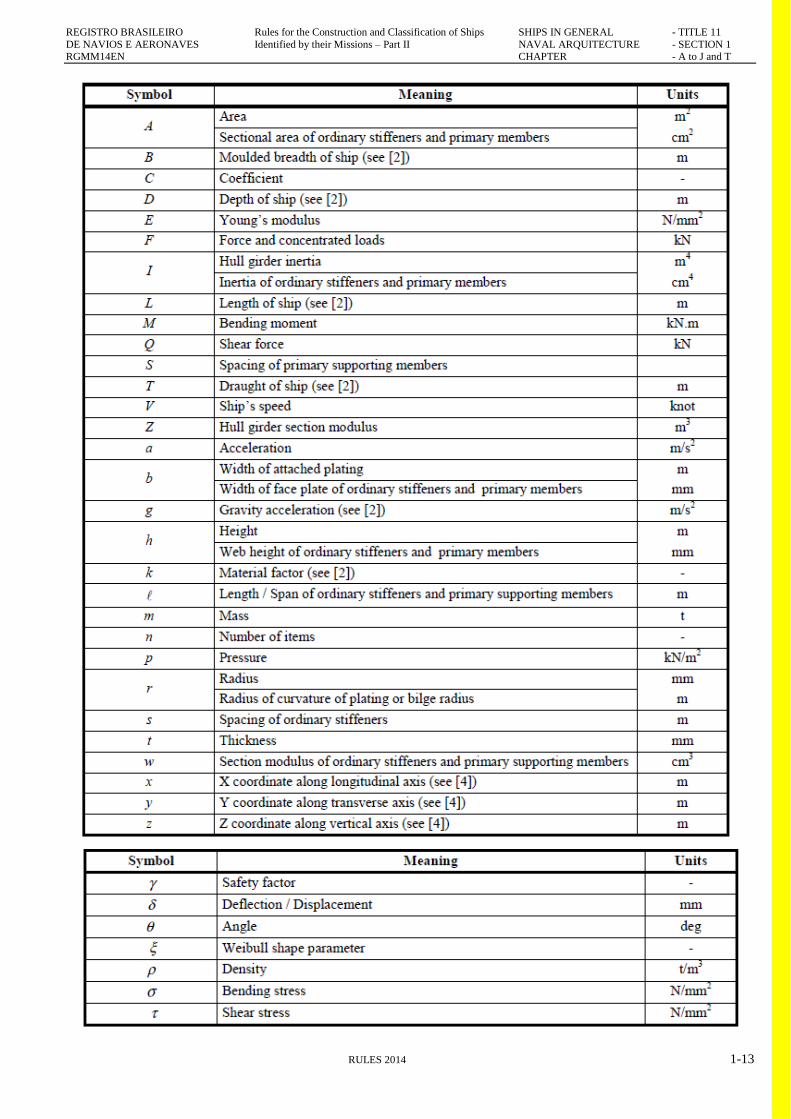
200. Symbols used in Subchapter C2
201. Primary symbols
REGISTRO BRASILEIRO Rules for the Construction and Classification of Ships SHIPS IN GENERAL - TITLE 11
DE NAVIOS E AERONAVES Identified by their Missions – Part II NAVAL ARQUITECTURE - SECTION 1 RGMM14EN CHAPTER - A to J and T
RULES 2014 1-13
REGISTRO BRASILEIRO Rules for the Construction and Classification of Ships SHIPS IN GENERAL - TITLE 11
DE NAVIOS E AERONAVES Identified by their Missions – Part II NAVAL ARQUITECTURE - SECTION 1 RGMM14EN CHAPTER - A to J and T
1-14 RULES 2014
202. Symbols for Loads
g : Gravity acceleration, taken equal to 9.81 m/s2
ρ: Sea water density, taken equal to 1.025 t/m3
ρ L : Density, in t/m3, of the liquid carried
ρ C : Density, in t/m3, of the dry bulk cargo carried
C : Wave parameter, taken equal to:
h : Height, in m, of a tank, to be taken as the vertical distance
from the bottom to the top of the tank, excluding any small
hatchways
zTOP : Vertical distance, in m, of the highest point of the tank
from the baseline. For ballast holds, zTOP is the vertical
distance, in m, of the top of the hatch coaming from the
baseline
lH : Length, in m, of the compartment
MSW : Design still water bending moment, in kN.m, at the hull
transverse section considered:
MSW = MSW,H in hogging conditions
MSW = M MSW,S in sagging conditions
MWV : Vertical wave bending moment, in kN.m, at the hull
transverse section considered:
MWV = MWV,H in hogging conditions
MWV = MWV,S in sagging conditions
MWH : Horizontal wave bending moment, in kN.m, at the hull
transverse section considered,
QSW : Design still water shear force, in kN, at the hull
transverse section considered
QWV : Vertical wave shear force, in kN, at the hull transverse
section considered
pS : Still water pressure, in kN/m2
pW : Wave pressure or dynamic pressures, in kN/m2
pSF, pWF : Still water and wave pressure, in kN/m2, in flooded
conditions
σX : Hull girder normal stress, in N/mm2
σX , aX, aY, aZ : Accelerations, in m/s2, along X, Y and Z
directions, respectively
TR : Roll period, in s
ϴ: Roll single amplitude, in deg
TP : Pitch period, in s
ϕ: Single pitch amplitude, in deg
kr : Roll radius of gyration, in m
GM : Metacentric height, in m
λ: Wave length, in m
203. Symbols for Parameters of Ship motions and
accelerations.
204. For symbols not defined in this Subchapter C2, refer
to Subchapter A2.
a0 : Acceleration parameter, taken equal to:
TR : Roll period, in s, defined in [2.1.1]
ϴ: Single roll amplitude, in deg, defined in [2.1.1]
TP : Pitch period, in s, defined in [2.2.1]
ϕ: Single pitch amplitude, in deg, defined in [2.2.1]
fp : Coefficient corresponding to the probability level, taken
equal to:
fp = 1.0 for strength assessments corresponding to
the probability level of 10-8
fp = 0.5 for strength assessments corresponding to
the probability level of 10-4
300. Ship’s motions and accelerations: General
301. Ship motions and accelerations are assumed to be
periodic. The motion amplitudes, defined by the formulae in
this Section, are half of the crest to trough amplitudes.
302. As an alternative to the formulae in this Section, the
RBNA may accept the values of ship motions and
accelerations derived from direct calculations or obtained
from model tests, when justified on the basis of the ship’s
characteristics and intended service. In general, the values of
ship motions and accelerations to be determined are those
which can be reached with a probability level of 10-8 or 10-4.
303. In any case, the model tests or the calculations,
including the assumed sea scatter diagrams and spectra, are to
be submitted to the RBNA for approval.

REGISTRO BRASILEIRO Rules for the Construction and Classification of Ships SHIPS IN GENERAL - TITLE 11
DE NAVIOS E AERONAVES Identified by their Missions – Part II NAVAL ARQUITECTURE - SECTION 1 RGMM14EN CHAPTER - A to J and T
RULES 2014 1-15
400. Ship absolute motions and accelerations
401. Roll: The roll period TR, in s, and the single roll
amplitude θ, in deg, are given by:
where:
kb : Coefficient taken equal to:
kb = 1.2 for ships without bilge keel
kb = 1.0 for ships with bilge keel
kr : Roll radius of gyration, in m, in the considered loading
condition. When kr is not known, the values indicated in Tab
1 may be assumed.
GM : Metacentric height, in m, in the considered loading
condition. When GM is not known, the values indicated in
Table T.C2.501.1 may be assumed.
Table T.C2.501.1: Values of kr and GM
Loading conditions kr GM
Full load condition (alternate or
homogeneous loading)
0,35B 0,12B
Normal ballast condition 0,45B 0,33B
Heavy ballast condition 0,40B 0,25B
402. Pitch: The pitch period TP, in s, and the single pitch
amplitude ϕ, in deg, are given by:
where:
403. Heave : The vertical acceleration due to heave, in
m/s2, is given by:
aheave = a0g
404. Sway: The transverse acceleration due to sway, in
m/s2, is given by:
asway = 0.3a0g
405. Surge: The longitudinal acceleration due to surge, in
m/s2, is given by:
asurge = 0.2a0 * g
a0 : Acceleration parameter, taken equal to (see C2.204
above):
500. Ship relative accelerations
501. General: At any point, the accelerations in X, Y and Z
directions are the acceleration components which result from
the ship absolute motions and accelerations defined in item
C2.502 below.
502. Accelerations: The reference values of the
longitudinal, transverse and vertical accelerations at any point
are obtained from the following formulae:
a. In longitudinal direction:
b. In transverse direction:
c. In a vertical direction:
where:
CXG, CXS, CXP, CYG, CYS, CYR, CZH, CZR and CZP :
Load combination factors defined in Ch 4, Sec 4, [2.2]
apitch x : Longitudinal acceleration due to pitch, in m/s2
aroll y : Transverse acceleration due to roll, in m/s2

REGISTRO BRASILEIRO Rules for the Construction and Classification of Ships SHIPS IN GENERAL - TITLE 11
DE NAVIOS E AERONAVES Identified by their Missions – Part II NAVAL ARQUITECTURE - SECTION 1 RGMM14EN CHAPTER - A to J and T
1-16 RULES 2014
aroll z : Vertical acceleration due to roll, in m/s2
apitch z : Vertical acceleration due to pitch, in m/s2
where x 0.45Lis to be taken not less than 0.2L
x, y, z : X, Y and Z co-ordinates, in m, of any point considered
with respect to the reference co-ordinate system defined in Ch
1, Sec 4
C3. ENVIRONMENT PRESERVATION
100. Compliance to Environmental Regulations
101. For vessels under the Brazilian Flag and with GT <
400, the regulatory prescriptions for environment protection
(Agency for Sanitary Regulation – ANVISA, law 9966
amended by Resolution RDC Nº 217, 21 of November 2001
are to be complied with.
102. For vessels under foreign flags with GT < 400,
National Regulations are to be complied with. In the absence
of such regulations, MARPOL regulations apply.
103. For vessels with GT ≥ 400, under Brazilian or foreign
flags, the requirements of
CHAPTER D
ACTIVITIES AND SERVICES
CHAPTER CONTENTS
D1. TYPES OF ACTIVITIES AND SERVICES
D2. OPERATION AND MAINTENANCE OF SHIPS
D1. TYPES OF ACTIVITIES AND SERVICES
100. Types of vessels in the present Rules
101. The Activities / services of the vessels covered by the
present Rules are classed in categories hereafter designated as
Titles (see definition in Part I, Title 01 Section 2, Chapter D,
sub-chapter D3).
102. The prescriptions for assigning a Class according to a
Title are given in Part II of the present Rules. Each Title is
subdivided into Sections, as follows:
a. Section 1 – Naval Architecture
b. Section 2 – Hull Structure
c. Section 3 – Hull Equipment
d. Section 4 – Accommodation
e. Section 5 – Machinery
f. Section 7 – Electricity
g. Section 8 – Nautical and Electronics
Each Section is subdivided into Chapters, Subchapters and
topics according to the ship's nature and mission.
200. Statutory surveys
201. For the purpose of statutory certification, vessels
under the Brazilian flag are to be in accordance with the
definitions of activities and services given in NORMAM 01,
Chapter 2, Section I, item 0216.
202. For vessels with GT < 500 under foreign flag the
definition of activities and services are to be in conformity
with the relevant National Regulations or, in absence of such
regulations, in conformity with the SOLAS regulations and/or
with the relevant IMO Codes.
202. For vessels with GT ≥ 500, under Brazilian or foreign
flags the definition of activities and services are to be in
conformity with the relevant SOLAS Chapters and/or with
the relevant IMO Codes

REGISTRO BRASILEIRO Rules for the Construction and Classification of Ships SHIPS IN GENERAL - TITLE 11
DE NAVIOS E AERONAVES Identified by their Missions – Part II NAVAL ARQUITECTURE - SECTION 1 RGMM14EN CHAPTER - A to J and T
RULES 2014 1-17
D2. OPERATION AND MAINTENANCE OF SHIPS
100. Adequate crew
101. The application of the present Rules is based on the
principle that the vessels are going to be loaded, operated and
maintained adequately by competent and qualified crew or
operating personnel, according to the environmental, loading,
operating and other criteria on which classification is based.
In particular, it will be assumed that the ship will not exceed
the draught of the assigned freeboard, or the maximum
allowed by Classification.
102. The RBNA interventions and the relevant reports
reflect the condition of the ship at the moment of the
intervention. It is the responsibility of the interested parties
to ensure proper maintenance until the next survey required
by the Rules.
103. The Interested Party has the duty of to inform the
Surveyor whenever circumstances occur that might affect the
ship's class.
CHAPTER E
CONFIGURATIONS
CHAPTER CONTENTS
E1. HULL ADEQUATION
E2.
BASIC ARRANGEMENT
E1. HULL COMPATIBILITY
100. Sailing characteristics
101. The present Rules are based on the assumption that the
hull shape and arrangement are compatible with the
navigation zone of the vessel.
200. Navigation aids
201. The present Rules are based upon the assumption that
instruments and information such as nautical charts, echo-
sounder, etc. sufficient for the control of the navigating
conditions as well as environmental control are available and
are adequate for the navigation zone and applicable
Regulations.
E2. BASIC GENERAL ARRANGEMENT
100. Location of cargo spaces
101. In cargo or passenger vessels, the cargo spaces may be
located inside the hull or over the hull, giving due
consideration to the buoyancy and water tightness conditions
as per load line and stability regulations. See Chapter G and
H below.
102. The general arrangement of tankers must be in
accordance with the ships covered under the Group 30 of the
present Rules.
103. For passenger vessel, see Part II, Title 21, Section 1.
104. For roll-on roll off cargo vessels, see Part II, Title 15,
Section 1. For roll on roll off passenger or cargo and
passenger vessels, see Part II, Title 26, Section 1.
200. Engine Room location
201. In general, the engine Room may be located amidships
or aft.
202. In special type vessels, the Engine Room may be
located forward or over the deck, or else the ship may be
fitted with two Engine Rooms such as in dredgers and oil
tankers, one of them generally for main services and/or
pumps.
203. Catamaran type vessels (double hull) may have
separate Engine Rooms, one in each hull.
300. Accommodation location
301. Accommodation space may be under or over the deck
under the conditions of:
a. For vessels under 500 GT, the National
Administration regulations, which in Brazilian Flag
ships are those of NORMAM 01;
b. For vessels with GT equal to 500 GT and over, and for
vessels which have no National Administration
regulations, the IMO regulations.
302. For Class certification, the requirements of the present
Chapter are applicable, and additional regulations are to be
found in the relevant Titles according to the mission of the
vessel.
303. See also Part II, Title 11, Section 4 of Rules.
REGISTRO BRASILEIRO Rules for the Construction and Classification of Ships SHIPS IN GENERAL - TITLE 11
DE NAVIOS E AERONAVES Identified by their Missions – Part II NAVAL ARQUITECTURE - SECTION 1 RGMM14EN CHAPTER - A to J and T
1-18 RULES 2014
CHAPTER F
HULL SHAPE AND DIMENSIONS
CHAPTER CONTENTS
F1. DIMENSIONS
F2. HULL SHAPE
F1. DIMENSIONS
100. Hull dimensions and proportions
101. The hull forms and dimensions for the design speed
and mission are to be within the boundaries imposed by the
Class Notation restrictions related to the navigation zone as
defined in Part I, Title 01, Section 1 of the Rules, in
conjunction with the prescriptions of Part II, Title 11, Section
2 of the present Rules.
F2. HULL FORMS
100. Focus on hull shape
101. The present Rules apply to the safety of navigation of
the vessels, and not specifically to the performance of the
hull.
CHAPTER G
SUBDIVISION
CHAPTER CONTENTS
G1. CAPACITIES
G2. SUBDIVISION
G1. CAPACITIES
100. Volumes and volume centres
101. The capacity of the cargo holds, tanks, etc. are to be
submitted in plans and tables (including sounding tables),
indicating the geometry, location and volumes, the centres of
gravity as well as the free surface of the tanks at several
levels.
G2. HULL SUBDIVISION
100. Compartments, tanks and empty spaces
101. The subdivision of the hull by bulkheads of
compartments, tanks and empty spaces will take into
consideration the nature of their contents, attending specific
requirements presented in the present Rules and in the
Regulations.
102. As to subdivision for buoyancy, see sub-chapter H4
below.
103. The Engine Room will be restricted by bulkheads. In
case the Engine Room is located aft of the vessel, the aft
bulkhead of the engine Room may be the aft peak bulkhead
of the vessel.
104. Where vehicles are carried inside the holds, special
consideration will be given by RBNA, including double hull
construction.
200. Cofferdams
201. A cofferdam is an empty space separating adjacent
compartments. A cofferdam may be arranged vertically or
horizontally, adequately ventilated and of sufficient
dimensions to allow access for inspection.
202. Cofferdams are to be installed between:
a. Fuel oil and lubricating oil tanks;
b. Compartments destined to liquid hydrocarbons and
fresh water compartments;
c. Compartments destined to liquid hydrocarbons and
liquid foam for fire extinguishing.
203. Spaces destined to carry flammable liquids: where
the accommodation or service area is located immediately
over one of such cargo spaces, the requirement for a
cofferdam may be exempted only in case the deck is not fitted
with access openings and coated by an adequate material
subject to RBNA approval.
204. Where the dimension of the cofferdams is excessive
when compared to the dimensions of the adjacent tank or
tanks, an exemption may be granted by RBNA upon
assessment and in case the following conditions are complied
with:
a. An increase of 2 mm must be added in the thickness of
the plating between the tanks in relation to Part II Title
11 Section 2 item .F2.600 of the Rules for fresh water
tanks and 1 mm in all other cases.
b. The sum of the welding seam thicknesses must not be
less than the thickness of the bulkhead;
c. The height of a water column employed in the design
structural calculations as well as the height employed
at the water tightness and structural strength tests is to
be increased by 1 (one) meter in relation to item Part
II, Title 11, Section 2,item T6 of the Rules.
REGISTRO BRASILEIRO Rules for the Construction and Classification of Ships SHIPS IN GENERAL - TITLE 11
DE NAVIOS E AERONAVES Identified by their Missions – Part II NAVAL ARQUITECTURE - SECTION 1 RGMM14EN CHAPTER - A to J and T
RULES 2014 1-19
CHAPTER H
LOADING CONDITIONS, BUOYANCY AND
STABILITY
CHAPTER CONTENTS
H1. LOAD LINE
H2. SHIP LIGHT WEIGHT
H3. LOADING CONDITIONS
H4. BUOYANCY AND HULL SUBIVISION
H5 STABILITY
H1. LOAD LINE
100. Load line assignment
101. The conformity of the load line assignment in
compliance with the existing regulations is to be verified by
RBNA jointly with the analysis of the structural resistance
and stability
102. The conformity of the physical conditions for
compliance with the existing regulations is to be verified by
RBNA.
103. For ships under the Brazilian Flag with GT < 500, the
requirements for the assignment of the load line are to be in
conformity with the requirements of NORMAM 01 (Norma
da Autoridade Marítima Brasileira para Navegação em Mar
Aberto, Chapter 7).
104. For ships under foreign Flags with GT < 500, the
requirements for the assignment of the load line are to be in
conformity with the requirements of the National
Administration and, in the absence of such requirements, in
conformity with the ILC Convention, as far as practicable.
[(IACS Rec 99 Chapter II)]
105. For ships having GT ≥ 500 the requirements of ILLC -
International Load Line Convention are to be complied with.
The application of the relevant IACS Unified Interpretations
(UI) is mandatory.
H2. LIGHT SHIP WEIGHT
100. Determination of the light ship weight
101. The vessel’s light weight value including the
equipment on board are determined and tested, together with
the centre of gravity coordinates.
102. In vessels with GT > 50, this determination is made
through the inclination experiment.
103. In vessels with GT ≤ 50 (except passenger or special
vessels), the inclination test can be substituted by the
"weights and centres estimate", under the condition that the
weights and centres be checked by measurement of the drafts
(see relevant item).
104. In vessels where the bending moment is calculated, the
curve (or table) of weight distribution is to be determined and
submitted.
H3. LOADING CONDITIONS
- See Chapter H5 below.
H4. BUOYANCY AND SUBDIVISION OF THE
HULL
100. Principles
101. The integrity of the hull, responsible for the hull’s
floatability, i.e., the up thrust, is to be preserved by the
arrangements of prevention against flooding.
102. Hatch ways and other access openings for cargo tanks
or cargo holds on the main deck, giving access to the interior
of the hull, must be fitted with covers or manholes as required
by Part II, Section 3 of the Rules.
103. Compartments under the main deck, such as
accommodations and Engine Room, having access through
openings in the main deck protected by superstructure or deck
houses, will not have direct access to the outside unless
through an emergency opening.
104. The compartments at main deck level fitted with water
tight doors will have other means of going out in such a way
that the watertight doors remain closed in case of bad weather
or tilting.
105. When a ship having a length less than 80 m and a
tonnage of 500 GT and over is fitted with single cargo hold or
cargo holds below the freeboard deck, which are not
separated by at least one bulkhead made watertight up to the
freeboard deck, a water ingress detection system is to be
fitted.
106. Bulk Carriers: For ships granted with the service
notation bulk carrier, bulk carrier ESP, ore carrier ESP,
combination carrier/OBO ESP or combination carrier /OOC
ESP, a water ingress detection system is to be fitted.
200. Subdivision bulkheads to contain flooding
201. All ships are to have at least the following transverse
watertight bulkheads:
a. one collision bulkhead
REGISTRO BRASILEIRO Rules for the Construction and Classification of Ships SHIPS IN GENERAL - TITLE 11
DE NAVIOS E AERONAVES Identified by their Missions – Part II NAVAL ARQUITECTURE - SECTION 1 RGMM14EN CHAPTER - A to J and T
1-20 RULES 2014
b. one after peak bulkhead for passenger ships and roll
on –roll off passenger ships
c. two bulkheads forming the boundaries of the
machinery space in ships with machinery amidships,
and a bulkhead forward of the machinery space in
ships with machinery aft. In the case of ships with an
electrical propulsion plant, both the generator room
and the engine room are to be enclosed by watertight
bulkheads.
202. Subdivision and Damage Stability: Vessels of
applicable size, type and service are to have subdivision and
damage stability as required by the SOLAS - International
Convention for the Safety of Life as Sea, 1974/1988, as
amended, as follows:
a. Passenger vessel — Regulation II-1/4 through 8-1
(Part II, Title 21)
b. Cargo vessel — Regulation II-1/4 through 7-3 (Part II,
Title 11)
c. Gas carrier — IGC Code (Part II, Title 34)
d. Chemical carrier — IBC Code (Part II, Title 33).
203. Bulk carriers for which the request for class for new
construction is received on or after 1 July 1998 are to meet
the requirements in Appendix 3-3-A2 of the SOLAS
conventions, ―Subdivision and Damage Stability
Requirements for Bulk Carriers‖.
204. All ships, shall be fitted with a collision bulkhead in
conformity with NORMAM 01, chapter 7 for ships with GT
< 500; and SOLAS II01, Part B-2, Regulation 12 for ships
with GT ≥ 500.
205. The collision bulkhead shall be located at a Rules
distance from the forward perpendicular dc, basically of the
following order:
dc ≥ 0,05 × L
dc ≤ 0,125 × L
or 10 m, whichever is less.
Guidance
In case of discrepancies between the National or
International regulations, the strictest parameters are to be
adopted.
End of guidance
206. No doors, manholes, access openings, ventilation
ducts or any other openings shall be fitted in the collision
bulkhead below the bulkhead deck.
207. All ships with GT ≥ 500: where any part of the ship
below the waterline extends forward of the forward
perpendicular, e.g., a bulbous bow, the distances stipulated in
H4.205 shall be measured from a point either:
a. at the mid-length of such extension;
b. at a distance 0.015L forward of the forward
perpendicular; or
c. at a distance 3 m forward of the forward
perpendicular, whichever gives the smallest
measurement.
208. The bulkhead may have steps or recesses provided
they are within the limits prescribed in H4.207 above.
209. All ships: An aft collision bulkhead shall be fitted at a
Rules distance from the stern of the order of 0,04 a 0,08 x L.
In self-propelled vessels the aft collision bulkhead may be
located at the inner extremity of the stern tube. Where a
special arrangement of the stern exists, this is to be submitted
to RBNA for approval.
210. The Engine Room shall be limited by two bulkheads.
Where the Engine Room is aft, the aft bulkhead of the Engine
Room, may be the aft collision bulkhead.
211. Further to the above bulkheads, common transverse
watertight bulkheads (AEC) shall be built. The spacing
between two bulkheads shall not exceed 14% to 33% of the
length L.
212. For vessels fitted with a single hold, double hull
construction may be considered as an alternative.
213. In cases where the damage stability calculation and/or
flooded length is required the spacing between the transverse
watertight bulkheads is to be determined by those
calculations.
Guidance
In case of discrepancies with the National or International
regulations, the strictest parameters are to be adopted.
End of guidance
300. Vertical subdivision
301. Where the accommodation floor is below the
maximum draft waterline, the distance between the floor and
the waterline shall not exceed one meter.
400. Hull openings and means of closure
401. The upper end of the coamings, ventilation ducts, the
height of the sills of access openings and the lower end of the
―U‖ pipe in air vents, must be in conformity with the
distances required in IMO ILLC – International Load Line
Convention – and NORMAM 1, Chapter 6 (National
Administration Requirements), where applicable.

REGISTRO BRASILEIRO Rules for the Construction and Classification of Ships SHIPS IN GENERAL - TITLE 11
DE NAVIOS E AERONAVES Identified by their Missions – Part II NAVAL ARQUITECTURE - SECTION 1 RGMM14EN CHAPTER - A to J and T
RULES 2014 1-21
402. The permanent watertight means of closure of the hull
openings are detailed in Part II, Section 3 of the present
Rules.
500. Angle of flooding
501. "Angle of flooding" means that angle of heel at which
openings in the hull, superstructures or deckhouses that
cannot be closed weather tight immerse.
Guidance
Angle of flooding is the angle of heel at which the vessel’s
interior spaces are flooded by water through openings
considered to be open or openings which may be open as
required by operation conditions of the vessel in working
position.
End of guidance
502. The angle of flooding as defined in H5.501 above is to
be adopted for the stability calculations.
600. Minimizing the flooding effects
601. For ships with GT ≥ 500, the prescriptions for bilge
pumping and piping systems are to be in conformity with
NORMAM 01 Chapter 7, and Part II, Section 6 of the Rules.
602. For ships with GT < 500, the prescriptions for bilge
pumping and piping systems are to be in conformity with the
SOLAS International Convention Chapter II-1, Part C, Rule
35-1.
603. For passenger vessels and tankers, please refer to the
relevant Part II, Titles 21, 32, 33 and 34 of the Rules.
604. For cross-flooding in passenger vessels, refer to Part
II, Title 21, Section 1 of the Rules.
700. Minimizing the free surface effect
701. To minimize the free surface effect, longitudinal
watertight bulkheads will be built, which will be taken into
account in the stability calculations.
H5. INTACT STABILITY
100. Intact Stability
[IACS REC 24 and UR L2, IMO A.749(18 )
amended by MSC.267(85)]
[IACS UR L2]
101. All new ships with a length of 24 m and above will be
assigned class only after it has been demonstrated that their
intact stability is adequate for the service intended. Adequate
intact stability means compliance with standards laid down
by the relevant Administration or those of the Classification
Society taking into account the ship’s size and type. The
level of intact stability for ships of all sizes in any case shall
not be less than that provided by IMO IS Code as amended.
a. The criteria according to the type of ship is given in
Table T.H5.103.1.
102. Stability check – vessels with GT < 500 subject to
National Administration: The checking of the stability is
carried out by comparison with the standards of the National
and International Administrations. For ships with GT <500,
the present Rules follows the requirements of NORMAM 01.
103. For ships having GT ≥ 500 at least the following sets
of criteria in Table T.H5.103.1or their equivalents are to be
met:
Guidance
The IMO Intact Stability (IS) Code is applicable for ships
built on or after 1 Januaty 2010.
For ships built before 1 January 2010, the requirements and
criteria of the IMO Resolution A.749(18) as amended are to
be adopted as far as practicable. [(IACS Rec 99 Chapter
III)]
For ships of foreign flags under 500 GT, National
Administration regulations are to be assessed by RBNA or, in
the absence of such regulations, the IMO IS Code or the IMO
Resolution A.749 is to be adopted according to the age of the
ship.
End of guidance

REGISTRO BRASILEIRO Rules for the Construction and Classification of Ships SHIPS IN GENERAL - TITLE 11
DE NAVIOS E AERONAVES Identified by their Missions – Part II NAVAL ARQUITECTURE - SECTION 1 RGMM14EN CHAPTER - A to J and T
1-22 RULES 2014
TABLE T.H5.103.1 – STABILITY CRITERIA ACCORDING TO THE VESSEL’S TYPE
[IMO IS Code as amended]
[IACS Rec 24]
INTACT STABILITY
All ships ≥ 24 m in length IS Code Part A Chapter 2
Passenger ships IS Code Chapter 3 Part A* Chapter3 Section 3.1
Tankers of 5000 t DWT and above, type and
service for which the building contract is placed on
or after 1 February 1999 or, in the absence of a
building contract, the keels of which are laid or
which are in a similar stage of construction on or
after 1 August 1999
IS Code Chapter 3 Part A* Section 3.2
Regulation 27 in Annex I of the International Convention for
Prevention of Pollution from Ships, 1973/1978
Towing vessels The intact stability requirement of IMO Res. MSC.267(85),
Part A Chapter 2.2,
Alternatively, if applicable:
the intact stability requirement of IMO Res. MSC.267(85),
Part B Chapter 2.4
Additional requirements of IACS Rec 24
Offshore supply vessels The intact stability requirements of IMO Res. MSC.267(85),
Part A Chapter 2.3 and
Part B Chapter 2.4.
Special purpose ships The intact stability requirements of IMO Res. MSC.267(85),
Part A Chapter 2.3 and
Part B Chapter 2.5.
Cargo ships carrying timber deck cargoes IS Code Chapter 3 Part A* Section 3.3
Cargo ships carrying grain in bulk IS Code Chapter 3 Part A* Section 3.4
High speed craft IS Code Chapter 3 Part A* Section 3.5
Ice class notation ships IS Code Part A Chapter 2
Additionally to comply with IMO MCS/Circ.1056 –
Guidelines for Ships Operating in Arctic Ice Covered
Waters
104. For vessels to which requirements governing
subdivision and damage stability are applicable, the intact
stability shall be sufficient to meet such requirements in all
prescribed damage conditions.
105. Tankers for which that Regulation is not applicable are
to meet the requirements in Part II, Title 32, Section 1, sub-
chapter H5 item 700 ―Intact Stability of Tankers During
Liquid Transfer Operations.‖
106. Evidence of approval by the Administration concerned
may be accepted by RBNA for the purpose of classification.
107. In addition to the requirements of items H5.101 to 106
above, the requirements of the MARPOL convention 73/88
Annex I, regulation 27 and 28 are to be complied with.
108. The RBNA may allow the inclining test of an
individual ship as required by this sub-chapter H5 to be
dispensed with provided basic stability data are available
from the inclining test of a sister ship and it is shown to the
satisfaction of the RBNA that reliable stability information
for the exempted ship can be obtained from such basic data.
109. Stability test for pontoons: an inclining experiment is
not normally required for a pontoon, provided a conservative
value of the lightship vertical centre of gravity (KG) is
assumed for the stability calculations. The KG can be
assumed at the level of the main deck although it is
recognized that a lesser value could be acceptable if fully
documented. The lightship displacement and longitudinal
centre of gravity shall be determined by calculation based on
draught and density readings.
200. Conditions of loading
201. The intact stability calculations are to be based on the
following conditions of loading
a. All the intended cargo loading conditions are to be
included in the trim and stability booklet for
examination.

REGISTRO BRASILEIRO Rules for the Construction and Classification of Ships SHIPS IN GENERAL - TITLE 11
DE NAVIOS E AERONAVES Identified by their Missions – Part II NAVAL ARQUITECTURE - SECTION 1 RGMM14EN CHAPTER - A to J and T
RULES 2014 1-23
b. Further cases are subject to prior examination by the
RBNA before the loading; alternatively, an approved
loading instrument capable of performing damage
stability calculations in accordance with the
requirements in chapter H5 may be used.
c. For ships covered by this chapter the following
loading cases are to be included in the trim and
stability booklet, as applicable:
c.1. ship in the fully loaded departure condition at
the summer load waterline, with cargo
homogeneously distributed throughout all
cargo tanks and with full stores and
consumables
c.2. same condition as above, but with 10% stores
and consumables
c.3. ship in the departure condition loaded with a
cargo having a density in order to fill all cargo
tanks, with full stores and consumables, but
immersed at a draught less than the summer
load waterline
c.4. same condition as above, but with 10% stores
and consumables
c.5. ship in the fully loaded departure condition at
the summer load waterline, with cargo tanks
not entirely filled and with full stores and
consumables
c.6. same condition as above, but with 10% stores
and consumables
c.7. two loading conditions corresponding to
different cargo segregations in order to have
slack tanks with full stores and consumables
d. When it is impossible to have segregations, these
conditions are to be replaced by loading conditions
with the same specific gravity and with slack cargo
tanks same loading condition as above, but with 10%
stores and consumables
e. For oil tankers having segregated ballast tanks, the
lightship condition with segregated ballast only is also
to be included in the trim and stability booklet for
examination.
300. Weight distribution
301. The typical calculations for weight distribution
including cargo, consumables, etc. taking into considerations
the stages of the loading/unloading operations.
400. Free surface
[IACS UI LL61]
401. For all loading conditions, the initial metacentric
height and the righting lever curve shall be corrected for the
effect of free surfaces of liquids in tanks
402. Free surface effects shall be considered whenever the
filling level in a tank is less than 98% of full condition. Free
surface effects need not be considered where a tank is
nominally full, i.e. filling level is 98% or above. Free surface
effects for small tanks may be ignored under condition
specified in H5.215 of the present subchapter.
403. Nominally full cargo tanks shall be corrected for free
surface effects at 98% filling level. In doing so, the
correction to initial metacentric height shall be based on the
inertia moment of liquid surface at 5° of the heeling angle
divided by displacement, and the correction to righting lever
is suggested to be on the basis of real shifting moment of
cargo liquids.
404. Tanks which are taken into consideration when
determining the free surface correction may be in one of two
categories:
a. Tanks with filling levels fixed (e.g. liquid cargo, water
ballast). The free surface correction shall be defined
for the actual filling level to be used in each tank.
b. Tanks with filling levels variable (e.g. consumable
liquids such as fuel oil, diesel oil and fresh water, and
also liquid cargo and water ballast during liquid
transfer operations). Except as permitted in H5.408
and 5.409 below, the free surface correction shall be
the maximum value attainable between the filling
limits envisaged for each tank, consistent with any
operating instructions.
405. In calculating the free surface effects in tanks
containing consumable liquids, it shall be assumed that for
each type of liquid at least one transverse pair or a single
centreline tank has a free surface and the tank or combination
of tanks taken into account shall be those where the effect of
free surfaces is the greatest.
406. Where water ballast tanks, including anti-rolling tanks
and anti-heeling tanks, are to be filled or discharged during
the course of a voyage, the free surface effects shall be
calculated to take account of the most onerous transitory
stage relating to such operations.
407. For ships engaged in liquid transfer operations, the
free surface corrections at any stage of the liquid transfer
operations may be determined in accordance with the filling
level in each tank at that stage of the transfer operation.

REGISTRO BRASILEIRO Rules for the Construction and Classification of Ships SHIPS IN GENERAL - TITLE 11
DE NAVIOS E AERONAVES Identified by their Missions – Part II NAVAL ARQUITECTURE - SECTION 1 RGMM14EN CHAPTER - A to J and T
1-24 RULES 2014
408. Where water ballast tanks, including anti-rolling tanks
and anti-heeling tanks, are to be filled or discharged during
the course of a voyage, the free surface effects shall be
calculated to take account of the most onerous transitory
stage relating to such operations.
409. For ships engaged in liquid transfer operations, the
free surface corrections at any stage of the liquid transfer
operations may be determined in accordance with the filling
level in each tank at that stage of the transfer operation.
410. The corrections to the initial metacentric height and to
the righting lever curve are to be addressed separately as
indicated in H5.211 and H5.212.
411. In determining the correction to the initial metacentric
height, the transverse moments of inertia of the tanks are to
be calculated at 0 degrees angle of heel according to the
categories indicated in H5.212.
412. The righting lever curve may be corrected by any of
the following methods:
a. Correction based on the actual moment of fluid
transfer for each angle of heel calculated; corrections
may be calculated according to the categories
indicated in H5.211.
b. Correction based on the moment of inertia, calculated
at 0 degrees angle of heel, modified at each angle of
heel calculated; corrections may be calculated
according to the categories indicated in H5.211.
c. Correction based on the summation of Mfs (free
surface) values for all tanks taken into consideration
413. Whichever method is selected for correcting the
righting lever curve, only that method is to be presented in
the ship's trim and stability booklet. However, where an
alternative method is described for use in manually calculated
loading conditions, an explanation of the differences which
may be found in the results, as well as an example correction
for each alternative, are to be included.
414. The usual remainder of liquids in the empty tanks need
not be taken into account in calculating the corrections,
providing the total of such residual liquids does not constitute
a significant free surface effect.
415. The values of Mfs for each tank may be derived from
the formula:
Mfs = v × b × γ × k √δ
where:
Mfs is the free surface moment at any inclination, in m·tonnes
v is the tank total capacity, in m³
b is the tank maximum breadth, in m
γ is the mass density of liquid in the tank, in tonnes/m³
δ is equal to v/(b × l × h) (the tank block coefficient)
h is the tank maximum height, in m
l is the tank maximum length, in m
k is the dimensionless coefficient to be determined from table
T.H5.416.1 according to the ratio b/h. The intermediate
values are determined by interpolation.
417. Small tanks which satisfy the following condition
using the values of "k" corresponding to an angle of
inclination of 30°, need not be included in the correction:
Mfs / Δmin < 0.01 m
where:
Δmin is the minimum ship displacement calculated at dmin, in
tonnes
dmin is the minimum mean service draught of the ship without
cargo, with 10% stores and minimum water ballast, if
required, in m.
418. The usual remainder of liquids in empty tanks need
not be taken into account in calculating the corrections,
provided that the total of such residual liquids does not
constitute a significant free surface effect.
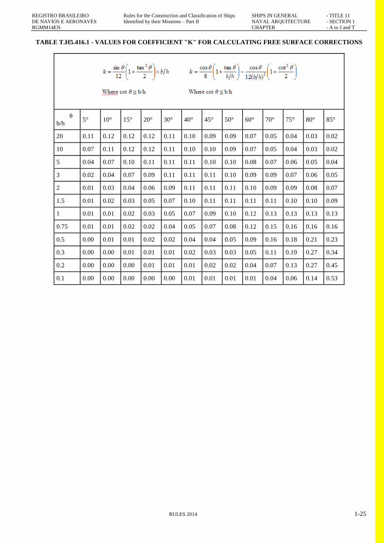
REGISTRO BRASILEIRO Rules for the Construction and Classification of Ships SHIPS IN GENERAL - TITLE 11
DE NAVIOS E AERONAVES Identified by their Missions – Part II NAVAL ARQUITECTURE - SECTION 1 RGMM14EN CHAPTER - A to J and T
RULES 2014 1-25
TABLE T.H5.416.1 - VALUES FOR COEFFICIENT "K" FOR CALCULATING FREE SURFACE CORRECTIONS
θ
b/h 5° 10° 15° 20° 30° 40° 45° 50° 60° 70° 75° 80° 85°
20 0.11 0.12 0.12 0.12 0.11 0.10 0.09 0.09 0.07 0.05 0.04 0.03 0.02
10 0.07 0.11 0.12 0.12 0.11 0.10 0.10 0.09 0.07 0.05 0.04 0.03 0.02
5 0.04 0.07 0.10 0.11 0.11 0.11 0.10 0.10 0.08 0.07 0.06 0.05 0.04
3 0.02 0.04 0.07 0.09 0.11 0.11 0.11 0.10 0.09 0.09 0.07 0.06 0.05
2 0.01 0.03 0.04 0.06 0.09 0.11 0.11 0.11 0.10 0.09 0.09 0.08 0.07
1.5 0.01 0.02 0.03 0.05 0.07 0.10 0.11 0.11 0.11 0.11 0.10 0.10 0.09
1 0.01 0.01 0.02 0.03 0.05 0.07 0.09 0.10 0.12 0.13 0.13 0.13 0.13
0.75 0.01 0.01 0.02 0.02 0.04 0.05 0.07 0.08 0.12 0.15 0.16 0.16 0.16
0.5 0.00 0.01 0.01 0.02 0.02 0.04 0.04 0.05 0.09 0.16 0.18 0.21 0.23
0.3 0.00 0.00 0.01 0.01 0.01 0.02 0.03 0.03 0.05 0.11 0.19 0.27 0.34
0.2 0.00 0.00 0.00 0.01 0.01 0.01 0.02 0.02 0.04 0.07 0.13 0.27 0.45
0.1 0.00 0.00 0.00 0.00 0.00 0.01 0.01 0.01 0.01 0.04 0.06 0.14 0.53

REGISTRO BRASILEIRO Rules for the Construction and Classification of Ships SHIPS IN GENERAL - TITLE 11 DE NAVIOS E AERONAVES Identified by their Missions – Part II NAVAL ARQUITECTURE - SECTION 1
RGMM14EN CHAPTER - A to J and T
1-26 RULES 2014
419. Small tanks which satisfy the following condition
using the values of "k" corresponding to an angle of
inclination of 30°, need not be included in the correction:
vbρk√δ/Δmin < 0.01 m
where
Δmin = the minimum ship displacement in tonnes.
420. The usual remainder of liquids in empty tanks need
not be taken into account in calculating the corrections
providing the total of such residual liquids does not constitute
a significant free surface effect.
500. Stability booklet
501. Each ship shall be provided with a stability booklet,
approved by the Administration, which contains sufficient
information to enable the master to operate the ship in
compliance with the applicable requirements contained in the
Code. The Administration may have additional
requirements. On a mobile offshore drilling unit, the stability
booklet may be referred to as an operating manual. The
stability booklet may include information on longitudinal
strength. This Code addresses only the stability-related
contents of the booklet. The format of the stability booklet
and the information included will vary dependent on the ship
type and operation. In developing the stability booklet,
consideration shall be given to including the following
information:
a. a general description of the ship;
b. instructions on the use of the booklet;
c. general arrangement plans showing watertight
compartments, closures, vents, downflooding angles,
permanent ballast, allowable deck loadings and
freeboard diagrams;
d. hydrostatic curves or tables and cross curves of
stability calculated on a free-trimming basis, for the
ranges of displacement and trim anticipated in normal
operating conditions;
e. capacity plan or tables showing capacities and centres
of gravity for each cargo stowage space;
f. tank sounding tables showing capacities, centres of
gravity, and free surface data for each tank;
g. information on loading restrictions, such as maximum
KG or minimum GM curve or table that can be used
to determine compliance with the applicable stability
criteria;
h. standard operating conditions and examples for
developing other acceptable loading conditions using
the information contained in the stability booklet;
i. a brief description of the stability calculations done
including assumptions;
j. general precautions for preventing unintentional
flooding;
k. information concerning the use of any special cross-
flooding fittings with descriptions of damage
conditions which may require cross-flooding;
l. any other necessary guidance for the safe operation of
the ship under normal and emergency conditions;
m. a table of contents and index for each booklet;
n. inclining test report for the ship, or:
n1. where the stability data is based on a sister
ship, the inclining test report of that sister ship
along with the lightship measurement report
for the ship in question; or
n2. where lightship particulars are determined by
other methods than from inclining of the ship
or its sister, a summary of the method used to
determine those particulars;
o. recommendation for determination of ship's stability
by means of an in-service inclining test.
502. As an alternative to the stability booklet mentioned in
the item H5.501 above, a simplified booklet in an approved
form containing sufficient information to enable the master to
operate the ship in compliance with the applicable provisions
of the Code as may be provided at the discretion of the
Administration concerned
503. Stability data and associated plans shall be drawn up
in the working language of the ship and any other language
the Classification RBNA may require. All translations of the
stability booklet shall be approved
504. As a supplement to the approved stability booklet, a
computer may be used to facilitate the stability calculations.
505. The computer hardware and software shall be
approved for stability calculation by the Administration. The
input/output format shall, as far as practicable, be easily
comparable in information and format to the stability booklet
so that the operators will easily gain familiarity with the
stability calculations.
506. A simple and straightforward instruction manual
written in the same language as the stability booklet,
complying with the provisions of H5.600, shall be provided
507. In order to validate the proper functioning of the
computer hardware and software, pre-defined standard
loading conditions shall be run in the computer periodically,
at intervals recommended by the suppliers but at least at
every annual load line inspection, and the printout shall be
maintained on board as check conditions for future reference

REGISTRO BRASILEIRO Rules for the Construction and Classification of Ships SHIPS IN GENERAL - TITLE 11 DE NAVIOS E AERONAVES Identified by their Missions – Part II NAVAL ARQUITECTURE - SECTION 1
RGMM14EN CHAPTER - A to J and T
RULES 2014 1-27
508. Ships with innovative design are to be provided with
additional information in the stability booklet such as design
limitations, maximum speed, worst intended weather
conditions or other information regarding the handling of the
craft that the Master needs to operate the ship.
600. Permanent ballast
601. If used, permanent ballast shall be located in
accordance with a plan approved by the Administration and
in a manner that prevents shifting of position. Permanent
ballast shall not be removed from the ship or relocated within
the ship without the approval of the Administration.
Permanent ballast particulars shall be noted in the ship's
stability booklet.
H6. DAMAGED STABILITY
100. Subdivision and Damage D Stability
101. The damage stability requirements in the present
Chapter H6 [SOLA parts B-1 through B-4} shall apply to
cargo ships of 80 m in length (L) and upwards and to all
passenger ships regardless of length but shall exclude those
cargo ships which are shown to comply with subdivision and
damage stability regulations in other instruments developed
by the IMO Regulations.
Reference is made to Part II, Title 21, Section 1, H6.
102. Vessels of applicable size, type and service are to
have subdivision and damage stability as required by the
International Convention for the Safety of Life as Sea, 1974,
as amended, as follows:
TABLE T.H6.1013.1 – DAMAGED STABIITY
CRITERIA
DAMAGED STABILITY
Passenger vessel SOLAS 74/88 Part B-1
Regulation II-1/B/4 through
II-1/B1/8-1
, Chapter II of Annex 2 to
resolution MSC 216(82)
Cargo vessel SOLAS 74/88 Part B-1
Regulation II-1/B1/4
through II-1/B1/7-3
Oil tanker Regulation 28, Annex I,
MARPOL 73/78
Gas carrier IGC Code Part II, Title 34 of
the Rules
Chemical carrier IBC Code Part II Title 33 of
the Rules
Bulk carriers 150m in length
constructed on or after 1 July
1999 and for cargoes of
density 1,000 kg/m3 and
above
SOLAS 74/88 Regulation
XII/4 ―Damage stability
requirements applicable to
bulk carriers‖
Offshore supply vessel IMO Resolution
MSC.235(82)
CHAPTER I
PROPULSION PERFORMANCE
CHAPTER CONTENTS
I1. PROPULSION POWER
I2. HIGH SPEED CRAFT
I1. PROPULSION PERFORMANCE
100. Selection of the propulsion system
101. The selection of propulsion power and propulsion
system is Owners’ convenience.
102. The present Rules cover the requirements for
minimum speed for manoeuvres of the order of 6.0 knots.
I2. HIGH SPEED CRAFT
100. Definition
101. High speed craft, as defined by the IMO
―INTERNATIONAL CODE OF SAFETY FOR HIGH
SPEED CRAFT‖ – HSC Code - is a craft capable of a

REGISTRO BRASILEIRO Rules for the Construction and Classification of Ships SHIPS IN GENERAL - TITLE 11 DE NAVIOS E AERONAVES Identified by their Missions – Part II NAVAL ARQUITECTURE - SECTION 1
RGMM14EN CHAPTER - A to J and T
1-28 RULES 2014
maximum speed in metres per second (m/s) equal to or
exceeding:
V= 3.7 x Δ 0.1667
where:
Δ = displacement corresponding to the design waterline (m³).
102. The specific requirements for high speed craft are
included in Part II, Title 25 of the Rules.
200. Special approach
201. High speed craft are subject to a special approach by
RBNA (see Part II, Title 25 of the Rules).
CHAPTER J
ON-BOARD COMPUTERS FOR STABILITY
CALCULATIONS
CHAPTER CONTENTS
J1. APPLICATION
J2. GENERAL PRINCIPLES
J3. CALCULATION SYSTEMS
J4. FUNCTIONAL REQUIREMENTS
J5. APPROVAL PROCEDURES
J6. OPERATION MANUAL
J7. REQUIREMENTS FOR LOADING
CONDITIONS, LOADING MANUALS AND
LOADING INSTRUMENTS
J1. APPLICATION
100. Application
[IACS UR L5.1]
101. The use of onboard computers for stability
calculations is not a requirement of class. However, a
stability software installed onboard shall cover all stability
requirements applicable to the ship.
Guidance
IACS UR are mandatory for class, and in the present case,
this Chapter J is according to IACS UR L5. Although this
used to be a statutory item, after IACS has considered
stability to be a matter of Class, requirements for loading
computers have become a Class matter as well.
End of guidance
102. This Chapter J, which requires only software
approval, applies to onboard computers which are provided
with software capable of performing stability calculations for
the vessel.
103. Active and passive systems are defined in item J1.102.
This Chapter J covers passive systems and the off-line
operation mode of active systems only.
104. The requirements in this Chapter J apply to stability
software on ships contracted for construction on or after 1
July 2005.
J2. GENERAL PRINCIPLES
[IACS UR L5.1]
100. General Principles
101. The scope of a stability calculation software shall be
in accordance with the stability information as approved by
the administration and shall at least include all information
and perform all calculations or checks as necessary to ensure
compliance with the applicable stability requirements.
102. Approved stability software is not a substitute for the
approved stability information, and is used as a supplement
to the approved stability information to facilitate stability
calculations.
103. The input/output information shall be easily
comparable with approved stability information so as to
avoid confusion and possible misinterpretation by the
operator relative to the approved stability information.
104. An operation manual is to be provided for the onboard
computer stability software.
105. The language in which the stability information is
displayed and printed out as well as the operation manual is
written shall be the same as used in the ship’s approved
stability information. The RBNA may require a translation
into a language considered appropriate.
106. The onboard computer software for stability
calculations is ship specific and the results of the calculations
are only applicable to the ship for which it has been
approved.
107. In case of modifications implying changes in the main
data or internal arrangement of the ship, the specific approval
of any original stability calculation software is no longer
valid. The software is to be modified accordingly and re-
approved.

REGISTRO BRASILEIRO Rules for the Construction and Classification of Ships SHIPS IN GENERAL - TITLE 11 DE NAVIOS E AERONAVES Identified by their Missions – Part II NAVAL ARQUITECTURE - SECTION 1
RGMM14EN CHAPTER - A to J and T
RULES 2014 1-29
J3. CALCULATION SYSTEMS IACS UR L5.2
100. General
101. A passive system requires manual data entry, an
active system replaces the manual entry with sensors reading
and entering the contents of tanks, etc., and a third system, an
integrated system, controls or initiates actions based on the
sensor-supplied inputs and is not within the scope of this
Chapter.
200. Types of Stability Software IACS UR L5.3
201. Three types of calculations performed by stability
software are acceptable depending upon a vessel’s stability
requirements:
a. Type 1: Software calculating intact stability only (for
vessels not required to meet a damage stability
criterion)
b. Type 2: Software calculating intact stability and
checking damage stability on basis of a limit curve
(e.g. for vessels applicable to SOLAS Part B-1
damage stability calculations, etc.) or previously
approved loading conditions and
c. Type 3: Software calculating intact stability and
damage stability by direct application of pre-
programmed damage cases for each loading condition
(for some tankers etc.)
J4. FUNCTIONAL REQUIREMENTS
100. Required data
[IACS UR L5.4.1]
101. The calculation program shall present relevant
parameters of each loading condition in order to assist the
Master in his judgement on whether the ship is loaded within
the approval limits. The following parameters shall be
presented for a given loading condition:
a. deadweight data;
b. lightship data;
c. trim;
d. draft at the draft marks and perpendiculars;
e. summary of loading condition displacement, VCG,
LCG and, if applicable, TCG;
f. downflooding angle and corresponding downflooding
opening;
g. compliance with stability criteria: Listing of all
calculated stability criteria, the limit
h. values, the obtained values and the conclusions
(criteria fulfilled or not fulfilled).
102. If direct damage stability calculations are performed,
the relevant damage cases according to the applicable rules
shall be pre-defined for automatic check of a given loading
condition.
103. A clear warning shall be given on screen and in hard
copy printout if any of the loading limitations are not
complied with. J4.104 below. The data are to be presented
on screen and in hard copy printout in a clear unambiguous
manner.
104. The data are to be presented on screen and in hard
copy printout in a clear unambiguous manner.
105. The date and time of a saved calculation shall be part
of the screen display and hard copy printout.
106. Each hard copy printout shall contain identification of
the calculation program including version number.
107. Units of measurement are to be clearly identified and
used consistently within a loading calculation.
200. Acceptable Tolerances IACS UR L5.5
201. Depending on the type and scope of programs, the
acceptable tolerances are to be determined differently,
according to J4.205 or J4 206 below. Deviation from these
tolerances shall not be accepted unless the RBNA considers
that there is a satisfactory explanation for the difference and
that there will be no adverse effect on the safety of the ship.
202. Examples of pre-programmed input data include the
following:
a. Hydrostatic data: Displacement, LCB, LCF, VCB,
KMt and MCT versus draught.
b. Stability data: KN or MS values at appropriate
heel/ trim angles versus displacement, stability limits.
c. Compartment data: Volume, LCG, VCG, TCG and
d. FSM/ Grain heeling moments vs level of the
compartment’s contents.
203. Examples of output data include the following:
a. Hydrostatic data: Displacement, LCB, LCF, VCB,
KMt and MCT versus draught as well as actual
draughts, trim.
b. Stability data: FSC (free surface correction), GZ-
values, KG, GM, KG/GM limits, allowable grain
heeling moments, derived stability criteria, e.g. areas
under the GZ curve, weather criteria.

REGISTRO BRASILEIRO Rules for the Construction and Classification of Ships SHIPS IN GENERAL - TITLE 11 DE NAVIOS E AERONAVES Identified by their Missions – Part II NAVAL ARQUITECTURE - SECTION 1
RGMM14EN CHAPTER - A to J and T
1-30 RULES 2014
c. Compartment data: Calculated Volume, LCG, VCG,
TCG and FSM/ Grain heeling moments vs level of the
compartment’s contents.
204. The computational accuracy of the calculation
program results shall be within the acceptable tolerances
specified in J4.205 e J4.206, of the results using an
independent program or the approved stability information
with identical input.
205. Programs which use only pre-programmed data from
the approved stability information as the basis for stability
calculations, shall have zero tolerances for the printouts of
input data. Output data tolerances are to be close to zero,
however, small differences associated with calculation
rounding or abridged input data are acceptable. Additionally
differences associated with the use of hydrostatic and
stability data for trims that differ from those in the approved
stability information, are acceptable subject to review by the
individual RBNA.
206. Programs which use hull form models as their basis
for stability calculations, shall have tolerances for the
printouts of basic calculated data established against either
data from the approved stability information or data obtained
using the approval authority’s model. Acceptable tolerances
shall be in accordance with Table T.J4.206.1.5.2
TABLE T.J4.206.1 – ACCEPTABLE TOLERANCES
Hull Form Dependent
Displacement 2%
Longitudinal center of buoyancy,
from AP
1% / 50 cm max
Vertical center of buoyancy 1% / 5 cm max
Transverse center of buoyancy 0.5% of B / 5 cm max
Longitudinal center of flotation,
from AP
1% / 50 cm max
Moment to trim 1 cm 2%
Transverse metacentric height 1% / 5 cm max
Longitudinal metacentric height 1% / 50 cm max
Cross curves of stability 5 cm
Compartment dependent
Volume or deadweight 2%
Longitudinal center of gravity,
from AP
1% / 50 cm max
Vertical centre of gravity 1% / 5 cm max
Transverse center of gravity 0.5% of B / 5 cm max
Free surface moment 2%
Shifting moment 5%
Level of contents 2%
Trim and stability
Draughts (forward, aft, mean) 1% / 5 cm max
GMt 1% / 5 cm max
GZ values 5% / 5 cm max
FS correction 2%
Downflooding angle 20
Equilibrium angles 10
Distance to unprotected openings
or
margin line from WL, if applicable
+/- 5% / 5 cm max
Areas under righting arm curve 5% or 0,0012mrad
Notes to Table T.J4.206.1
a. Deviation in % = {(base value-applicant’s value)/base
value} *100
b. Where the ―base value‖ may be from the approved
stability information or the RBNA’s computer model.
J5. APPROVAL PROCEDURES
100. Conditions of approval of the onboard software for
stability calculations
101. The onboard software used for stability calculations is
subject to approval, which is to include;
a. verification of type approval, if any;
b. verification that the data used is consistent with the
current condition of the ship.
c. verification and approval of the test conditions;
d. verification that the software is appropriate for the
type of ship and stability calculations required.
102. The satisfactory operation of the software with the
onboard computer(s) for stability calculations is to be
verified by testing upon installation (see Chapter T below).
A copy of the approved test conditions and the operation
manual for the computer/ software are to be available on
board.
200. General Approval (optional) IACS UR L5.6.1
201. Upon application to the RBNA for general approval of
the calculation program, the RBNA may provide the
applicant with test data consisting of two or more design data
sets, each of which is to include a ship’s hull form data,
subdivision data, lightship characteristics and deadweight
data, in sufficient detail to accurately define the ship and it’s
loading condition. Acceptable hull form and subdivision
data may be in the form of surface coordinates for modelling
the hull form and compartment boundaries, e.g.: a table of
offsets, or in the form of pre-calculated tabular data, e.g.:
hydrostatic tables, capacity tables, etc., depending upon the
form of data used by the software being submitted for
approval.
202. Alternatively, the general approval may be given
based on at least two test ships agreed upon between the
RBNA and the applicant.

REGISTRO BRASILEIRO Rules for the Construction and Classification of Ships SHIPS IN GENERAL - TITLE 11 DE NAVIOS E AERONAVES Identified by their Missions – Part II NAVAL ARQUITECTURE - SECTION 1
RGMM14EN CHAPTER - A to J and T
RULES 2014 1-31
203. In general, the software is to be tested for two types of
ships for which approval is requested, with at least one
design data set for each of the two types. Where approval is
requested for only one type of ship, a minimum of two data
sets for different hull forms of that type of ship are required
to be tested. For calculation software which is based on the
input of hull form data, design data sets shall be provided for
three types of ships for which the software is to be approved,
or a minimum of three data sets for different hull forms if
approval is requested for only one type of ship.
Representative ship types which require different design data
sets due to their hull forms, typical arrangements, and nature
of cargo include: tanker, bulk carrier, container ship, and
other dry cargo and passenger ships.
204. The test data sets shall be used by the applicant to run
the calculation program for the test ships. The results
obtained (together with the hydrostatic data and cross-curve
data developed by the program, if appropriate) shall be
submitted to the RBNA for the assessment of the program’s
computational accuracy.
205. The RBNA shall perform parallel calculations using
the same data sets and a comparison of these results will be
made against the applicant’s submitted program’s results.
300. Specific approval
[IACS UR L5.6.2]
301. The RBNA shall verify the accuracy of the
computational results and actual ship data used by the
calculation program for the particular ship on which the
program will be installed.
302. Upon application to the RBNA for data verification,
the RBNA and the applicant shall agree on a minimum of
four loading conditions, taken from the ship’s approved
stability information, which are to be used as the test
conditions. For ships carrying liquids in bulk, at least one of
the conditions shall include partially filled tanks. For ships
carrying grain in bulk, one of the grain loading conditions
shall include a partially filled grain compartment. Within the
test conditions each compartment shall be loaded at least
once. The test conditions normally are to cover the range of
load draughts from the deepest envisaged loaded condition to
the light ballast condition and shall include at least one
departure and one arrival condition.
303. The RBNA is to verify that the following data,
submitted by the applicant, is consistent with arrangements
and most recently approved lightship characteristics of the
ship according to current plans and documentation on file
with the RBNA, subject to possible further verification on
board:
a. Identification of the calculation program including
version number.
b. Main dimensions, hydrostatic particulars and, if
applicable, the ship profile.
c. The position of the forward and after perpendiculars,
and if appropriate, the calculation method to derive
the forward and after draughts at the actual position of
the ship’s draught marks.
d. Ship lightweight and centre of gravity derived from
the most recently approved inclining experiment or
light weight check.
e. Lines plan, offset tables or other suitable presentation
of hull form data if necessary for the RBNA to model
the ship.
f. Compartment definitions, including frame spacing,
and centres of volume, together with capacity tables
(sounding/ullage tables), free surface corrections, if
appropriate.
g. Cargo and Consumables distribution for each loading
condition.
304. Verification by the RBNA does not absolve the
applicant and shipowner of responsibility for ensuring that
the information programmed into the onboard computer
software is consistent with the current condition of the ship.
J6. OPERATION MANUAL
100. Operation Manual
[IACS UR L5.7]
101. A simple and straightforward operation manual is to
be provided, containing descriptions and instructions, as
appropriate, for at least the following:
a. installation
b. function keys
c. menu displays
d. input and output data
e. required minimum hardware to operate the software
f. use of the test loading conditions
g. computer-guided dialogue steps
h. list of warnings
J7. REQUIREMENTS FOR LOADING
CONDITIONS, LOADING MANUALS AND
LOADING INSTRUMENTS
[IACS UR S1]

REGISTRO BRASILEIRO Rules for the Construction and Classification of Ships SHIPS IN GENERAL - TITLE 11 DE NAVIOS E AERONAVES Identified by their Missions – Part II NAVAL ARQUITECTURE - SECTION 1
RGMM14EN CHAPTER - A to J and T
1-32 RULES 2014
100. General
101. RBNA considers that this Requirement satisfies
Regulation 10(1) of the International Convention on Load
Lines, 1966.
200. Application
201. These requirements* apply to all classed sea-going
ships of 65m in length and above which are contracted for
construction on or after 1st July 1998, and contain minimum
requirements for loading guidance information. For CSR
Bulk Carriers and Oil Tankers, these requirements apply in
addition to those of the Common Structural Rules.
300. Definitions
301. Loading Manual: a Loading Manual is a document
which describes:
a. the loading conditions on which the design of the ship
has been based, including permissible limits of still
water bending moment and shear force
b. the results of the calculations of still water bending
moments, shear forces and where applicable,
limitations due to torsional and lateral loads
c. the allowable local loading for the structure (hatch
covers, decks, double bottom, etc.)
Notes
a. For ships which were contracted for construction
before 1st July 1998, the relevant prior revisions of
this Unified Requirement as well as Members’
reservations to those revisions of this Unified
Requirement apply.
b. Certain additional requirements of Unified
Requirement S1A also apply to bulk carriers, ore
carriers and combination carriers of 150m length and
above.
302. Loading Instrument: a loading instrument is an
instrument, which is either analogue or digital, by means of
which it can be easily and quickly ascertained that, at
specified read-out points, the still water bending moments,
shear forces, and the still water torsional moments and lateral
loads, where applicable, in any load or ballast condition will
not exceed the specified permissible values.
a. An operational manual is always to be provided for
the loading instrument.
b. Single point loading instruments are not acceptable.
303. Category I Ships
a. Ships with large deck openings where combined
stresses due to vertical and horizontal hull girder
bending and torsional and lateral loads have to be
considered;
b. Ships liable to carry non-homogeneous loadings,
where the cargo and/or ballast may be unevenly
distributed. Ships less than 120 metres in length, when
their design takes into account uneven distribution of
cargo or ballast, belong to Category II;
c. Chemical tankers and gas carriers.
304. Category II Ships
a. Ships with arrangement giving small possibilities for
variation in the distribution of cargo and ballast, and
ships on regular and fixed trading pattern where the
Loading Manual gives sufficient guidance, and in
addition the exception given under Category I.
400. Annual and Special Survey
401. At each Annual and Special Survey, it is to be
checked that the approved loading guidance information is
available on board.
402. The loading instrument is to be checked for accuracy
at regular intervals by the ship's Master by applying test
loading conditions.
403. At each Special Survey this checking is to be done in
the presence of the Surveyor.
500. Loading Conditions, Loading Manuals and
Loading Instruments
501. An approved loading manual is to be supplied for all
ships except those of Category II with length less than 90m
in which the deadweight does not exceed 30% of the
displacement at the summer load line draft. In addition, an
approved loading instrument is to be supplied for all ships of
Category I of 100m in length and above.
600. Conditions of Approval of Loading Manuals
601. The approved Loading Manual is to be based on the
final data of the ship. The Manual is to include the design
loading and ballast conditions upon which the approval of the
hull scantlings is based.
CHAPTER T
INSPECTIONS AND TESTS FOR NAVAL
ACRHITECTURE
CHAPTER CONTENTS:
T1. TESTS DURING CONTRUCTION
T2. TESTS AT THE COMPLETION OF BUILDING

REGISTRO BRASILEIRO Rules for the Construction and Classification of Ships SHIPS IN GENERAL - TITLE 11 DE NAVIOS E AERONAVES Identified by their Missions – Part II NAVAL ARQUITECTURE - SECTION 1
RGMM14EN CHAPTER - A to J and T
RULES 2014 1-33
T3. SEA TRIALS
T4. INSTALLATION TESTING FOR ON-BOARD
COMPUTERS FOR STABILITY
CALCULATIONS
T5. IACS GUIDELINES AND
RECOMMENDATIONS FOR INCLINING
EXPERIMENT
T1. TESTS DURING CONTRUCTION
100. Dfrat marks measument
101. The positions of the draft markings must be measured
in the presence of a RBNA surveyor.
102. Load line markings
103. Load line markings must be measured in the presence
of a RBNA surveyor.
T2. TESTS AT THE COMPLETION OF BUILDING
100. Inclining experiment
101. The measurements will be carried out in conformity
with the proceedings of NORMAM 01, in the presence of a
RBNA surveyor, therein included the checking of the
weights by a calibrated device.
102. The proceedings are to be previously approved by
RBNA and shall be comprised of:
a. Loading condition at the test;
b. Calculation of the weights to be applied in the test;
c. Indication of the estimated angle of heel;
d. Positioning of the weight during the trials; and
e. Estimated positioning of the weighs or hoses,
checking that the devices have appropriate length and
course so that angles of about 2 to 2.5 degrees are
attained, with a course of approximately 10 cm.
103. The report of the test, containing the light weight and
the measured centres, will be sent to RBNA for approval.
104. For vessels under 500 GT, the inclining experiment is
to be carried out in conformity with:
For Brazilian Flag vessels with GT < 500, according to
NORMAM 01 chapter 3;
For foreign Flag vessels with GT < 500, according to
National Regulations or, in the absence of such regulations,
in conformity with IMO regulations and IACS Rec 31.
200. Deadweight Measurement (“draft survey”)
201. For vessels under 500 GT under the Brazilian flag,
and where allowed by NORMAM 01, Chapter 3 the inclining
experiment may be substituted by a ―Deadweight
Measurement‖
a. For vessels under 500 GT under foreign flags, and
where allowed by the National Administration, the
inclining experiment may be substituted by a
―Deadweight Measurement‖
202. The measurement of weights and the longitudinal and
transverse position of the centre of gravity is carried out
through the draft measurement, and is destined to verify
conformity with the preliminary Weight and Centres
Estimative. This measurement will be carried out in the
presence of a RBNA surveyor.
203. The proceedings for these measurements is the same
as in the inclining experiment for vessels under 500 GT,
where applicable.
204. For vessels having GT≥ 500, see Part II, Title 11,
Section 1, sub-chapter T.3
300. Tolerances for vessels
301. Where the draft and weight measurement is
applicable, the values must not exceed the following
tolerances:
For LCG : 1 % of L;
For TCG: 0,3 % of L; and
For light weight: 3 % of the estimated.
302. In case larger differences are observed, a full inclining
experiment is required.
Guidance
303. The Brazilian National Administration adopts
tolerances stricter than IMO requirements. The RBNA Rules
adopt the tolerances above for all ships.
End of guidance
T3. SEA TRIALS
100. Propulsion and manoeuvring performance
101. For self-propelled vessels or for an integrated convoy
behaving as one single vessel, sea trials are required to
measure the following performances:

REGISTRO BRASILEIRO Rules for the Construction and Classification of Ships SHIPS IN GENERAL - TITLE 11 DE NAVIOS E AERONAVES Identified by their Missions – Part II NAVAL ARQUITECTURE - SECTION 1
RGMM14EN CHAPTER - A to J and T
1-34 RULES 2014
a. Speed;
b. Turning circle;
c. Zig-zag steering;
d. Distance to stop the vessel through engine reversal
e. Distance to stop the vessel without engine reversal;
and
f. Tendencies of the vessel in reverse power
102. For measurement of the performance of equipments
and systems of the vessel, refer to the relevant Sections.
T4. INSTALLATION TESTING FOR ON-BOARD
COMPUTERS FOR STABILITY
CALCULATIONS
[IACS UR L5.8]
100. Installation Testing
101. To ensure correct working of the computer after the
final or updated software has been installed, it is the
responsibility of the ship’s Master to have test calculations
carried out according to the following pattern in the presence
of a RBNA surveyor:
102. From the approved test conditions at least one load
case (other than light ship) shall be calculated. Note: Actual
loading condition results are not suitable for checking the
correct working of the computer.
103. Normally, the test conditions are permanently stored
in the computer.
104. Steps to be performed:
a. Retrieve the test load case and start a calculation run;
compare the stability results with those in the
documentation.
b. Change several items of deadweight (tank weights and
the cargo weight) sufficiently to change the draught or
displacement by at least 10%. The results are to be
reviewed to ensure that they differ in a logical way
from those of the approved test condition.
c. Revise the above modified load condition to restore
the initial test condition and compare the results. The
relevant input and output data of the approved test
condition are to been replicated.
d. Alternatively, one or more test conditions shall be
selected and the test calculation performed by entering
all deadweight data for each selected test condition
into the program as if it were a proposed loading. The
results shall be verified as identical to the results in
the approved copy of the test conditions.
200. Periodical Testing
201. It is the responsibility of the ship’s master to check the
accuracy of the onboard computer for stability calculations at
each Annual Survey by applying at least one approved test
condition.
202. If a RBNA surveyor is not present for the computer
check, a copy of the test condition results obtained by the
computer check is to be retained on board as documentation
of satisfactory testing for the surveyor’s verification.
203. At each Special Survey this checking for all approved
test loading conditions is to be done in presence of the
surveyor.
REGISTRO BRASILEIRO Rules for the Construction and Classification of Ships SHIPS IN GENERAL - TITLE 11 DE NAVIOS E AERONAVES Identified by their Missions – Part II NAVAL ARQUITECTURE - SECTION 1
RGMM14EN CHAPTER - A to J and T
RULES 2014 1-35
204. The testing procedure shall be carried out in
accordance with T4.100 above.
T5. IACS GUIDELINES AND
RECOMMENDATIONS FOR INCLINING
EXPERIMENT
[IACS REC 31 MODIFIED]
Guidance
The IACS Guidelines and Recommendations for Inclining
Experiment have been modified where different from
NORMAM 01, the National Administration regulations. The
modifications are clearly stated in the following text.
For ships under the Brazilian Flag, the NORMAM 01
additional / substitutive requirements are to be followed.
End of Guidance
100. General Preparation for the Test
101. Information to be submitted: the Instruction,
containing the information of date and location of the test,
responsible person, stability inclining weight, schemes of
inclining weight positions etc., shall be presented to the
Classification RBNA before the inclining test. The following
information shall be available at the time of the inclining test
as necessary:
a. General arrangement drawing;
b. Tank capacity plan;
c. Hydrostatic curves;
d. Draft marks locations.
200. The inclining test condition
201. The ship shall be as near to completion as possible.
Equipment used by the yard on board shall be limited to the
utmost extent possible. Prior to the inclining test, lists of all
items which are to be added, removed, or relocated shall be
prepared. These weights and their locations shall be
accurately recorded. Normally, the total value of missing
weights shall not exceed 2 percent and surplus weights,
excluding liquid ballast, not exceed 4 percent of the light ship
displacement. For smaller vessels, higher percentages may
be allowed.
202. All objects shall be secured in their regular positions.
All weights which may swing or shift must be secured in
their known position. If more than one sea stowage position
is possible, the actual stowage position used during the test
shall be recorded.
a. Additional National Administration requirements
(NORMAM 01)
a.1. Booms of lifting appliances, lifeboats, or jibs
must be fixed in the position ―stowed for
voyage‖ when taking the readings, and
a.2. Hatch covers must be closed where possible.
203. The ship shall be cleared of residues of cargo, tools,
debris, scaffolding and snow. Icing of the inner and outer
surfaces, the underwater hull included, is not permitted.
204. All bilge water and other extraneous standing liquids
must be removed. When draining individual tanks is
impracticable, allowances for such liquids shall be at the
discretion of the RBNA.
205. All service tanks and machinery plant piping are to be
filled as for the working condition.
206. In general, only the people participating in the
inclining test shall stay on board the ship.
a. Additional National Administration requirements
(NORMAM 01)
a.1. The people remaining on board must be
stationed at the centre line.
207. All spaces shall be safe for inspection.
208. Preferably, all tanks shall be either full or empty. The
number of tanks containing liquids shall be kept to a
minimum.
209. Soundings and density of liquids in tanks shall be
taken. Shapes of tanks which are partly filled are to be known
in order to determine the free liquid surface effect.
210. Adequate measures are to be taken to preclude air
pockets in completely full tanks. All connections between
tanks are to be closed and all empty tanks are to be
adequately dried.
a. Additional National Administration requirements
(NORMAM 01)
a.1. Where tanks cannot be totally full or empty
due to trim / stability reasons, care must be
taken to keep them at a level where free
surface determination is possible. This level is
to be kept constant throughout the test.
211. Mooring lines shall be free of any tension in the
transverse direction of the ship during the reading after each
weight shift. No external moments shall be brought upon the
ship (from mooring lines, quay, etc.). If possible, the ship
shall be located in a calm, protected area free from external
forces.
212. The depth of water under the hull shall be sufficient to
ensure that the hull will be entirely free of the bottom. Prior
to the test the depth of water shall be measured in as many
REGISTRO BRASILEIRO Rules for the Construction and Classification of Ships SHIPS IN GENERAL - TITLE 11 DE NAVIOS E AERONAVES Identified by their Missions – Part II NAVAL ARQUITECTURE - SECTION 1
RGMM14EN CHAPTER - A to J and T
1-36 RULES 2014
locations as necessary to positively satisfy this requirement,
taking into account tide differences, if applicable.
213. An ideal mooring arrangement would involve bow
and stern lines on both sides of the ship attached at or near
the centre-line. Longitudinal mooring lines shall be as long
as practicable. More commonly, a ship may be moored by
bow and stern lines on one side only and supplemented by
spring lines. Where a single bow or stern line is proposed,
the surveyor shall be assured that the ship’s freedom of
movement does not adversely effect the conduct of the
experiment.
214. The ship may be moored by means of other special
arrangement approved by the RBNA.
215. When tidal currents are present the experiment shall
normally be conducted at or around slack tide.
216. The ship’s gangway shall be in the stowed position
and any shore gangway removed during the inclining test. As
few cables, hoses, etc., as possible shall be connected to
shore. Those which are needed shall be slack.
217. The test shall not be conducted under adverse wind,
wave and current conditions where the accuracy of the results
cannot be assured.
300. Inclining Weights, pendulum and instruments
301. For the inclining test, solid inclining weights normally
shall be used.
302. Use of water ballast transfer to incline the vessel may
be permitted only in cases where it is impractical to incline
the vessel using solid weights. If the transfer of water ballast
is to be used, a detailed procedure, including calculation
procedure, is to be submitted to the RBNA for approval prior
to the experiment.
303. The total weight used shall be sufficient to provide a
minimum inclination of one degree and a maximum of four
degrees of heel to each side of the initial position. However,
in those cases where it is absolutely impractical to reach a
minimum angle of 1 degree by use of solid weights or water
ballast a lesser inclination angle may be accepted, provided
that the requirements on pendulum deflection or U-tube
difference in height are complied with.
304. Each weight is to be compact, impervious to water
and shaped such that its centre of gravity may be accurately
determined. It is recommended that not fewer than four
weights (or sets of weights) be used, each approximately
equal in mass, and that the inclining weights (or sets of
weights) be positioned as symmetrically as possible and
parallel to the centre line in places convenient for the shifting
of weights and measurement of the arms.
305. Each inclining weight shall be marked with an
identification number. The inclining weights shall have been
weighed with a calibrated instrument to the satisfaction of the
Surveyor.
306. The use of three measuring devices is recommended
to determine the vessel’s inclination after each weight shift,
however, a minimum of two devices shall be used, one of
which is to be a pendulum or U-tube arrangement. The
length and arrangement of pendulum/U-tube are to be such as
to ensure the accuracy of the readings of
deflection/difference. The minimum deflection/difference, to
each side of the initial position, corresponding to the total
weight shift, shall be 15cm.
307. The use of a stabilograph is also acceptable provided
the calibration of the instrument has been verified to the
Surveyor's satisfaction prior to the experiment. A trace of the
recorded heel pattern is to be included in the test report.
308. Additional National Administration requirements
(NORMAM 01) Moving weights
a. The moving weights are to be determined by means of
the following equation:
P = Δ GM tg θ), where:
d
P = total weight to be transferred, in metric tons;
Δ = Estimated displacement for the trial, in metric
tons;
GM = initial metacentric height estimated for the trial
condition, in meters;
d = transversal path of the inclining weight, in meters;
and
θ = inclining angle generated by moving the inclining
weights , recommended to be within a range as
follows:
1° < θ < 3°,
depending upon the ships particulars.
b. Liquid ballast weight is allowed only where solid
weights are considered absolutely and technically
impracticable.
c. Where liquid ballast is used as weight, care shall be
taken as follows:
c.1. Liquid transfer must be only between directly
symmetrical tanks;
c.2. The density of the liquid is to be measured;
c.3. Piping lines for the transfer are to be filled up
before the commencement of the trial and a
strict control is to be maintained over the valve
manoeuvres.
c.4. The level of liquid in the tanks to be employed
for the liquid transfer must be such as to allow
for measurement of the free surface
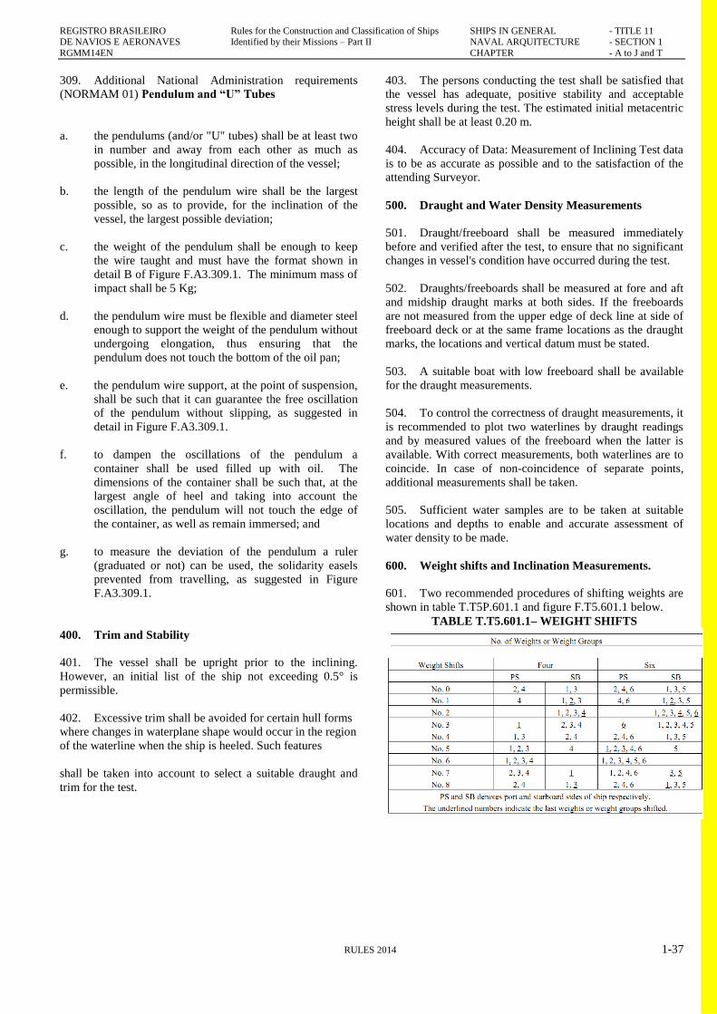
REGISTRO BRASILEIRO Rules for the Construction and Classification of Ships SHIPS IN GENERAL - TITLE 11 DE NAVIOS E AERONAVES Identified by their Missions – Part II NAVAL ARQUITECTURE - SECTION 1
RGMM14EN CHAPTER - A to J and T
RULES 2014 1-37
309. Additional National Administration requirements
(NORMAM 01) Pendulum and “U” Tubes
a. the pendulums (and/or "U" tubes) shall be at least two
in number and away from each other as much as
possible, in the longitudinal direction of the vessel;
b. the length of the pendulum wire shall be the largest
possible, so as to provide, for the inclination of the
vessel, the largest possible deviation;
c. the weight of the pendulum shall be enough to keep
the wire taught and must have the format shown in
detail B of Figure F.A3.309.1. The minimum mass of
impact shall be 5 Kg;
d. the pendulum wire must be flexible and diameter steel
enough to support the weight of the pendulum without
undergoing elongation, thus ensuring that the
pendulum does not touch the bottom of the oil pan;
e. the pendulum wire support, at the point of suspension,
shall be such that it can guarantee the free oscillation
of the pendulum without slipping, as suggested in
detail in Figure F.A3.309.1.
f. to dampen the oscillations of the pendulum a
container shall be used filled up with oil. The
dimensions of the container shall be such that, at the
largest angle of heel and taking into account the
oscillation, the pendulum will not touch the edge of
the container, as well as remain immersed; and
g. to measure the deviation of the pendulum a ruler
(graduated or not) can be used, the solidarity easels
prevented from travelling, as suggested in Figure
F.A3.309.1.
400. Trim and Stability
401. The vessel shall be upright prior to the inclining.
However, an initial list of the ship not exceeding 0.5° is
permissible.
402. Excessive trim shall be avoided for certain hull forms
where changes in waterplane shape would occur in the region
of the waterline when the ship is heeled. Such features
shall be taken into account to select a suitable draught and
trim for the test.
403. The persons conducting the test shall be satisfied that
the vessel has adequate, positive stability and acceptable
stress levels during the test. The estimated initial metacentric
height shall be at least 0.20 m.
404. Accuracy of Data: Measurement of Inclining Test data
is to be as accurate as possible and to the satisfaction of the
attending Surveyor.
500. Draught and Water Density Measurements
501. Draught/freeboard shall be measured immediately
before and verified after the test, to ensure that no significant
changes in vessel's condition have occurred during the test.
502. Draughts/freeboards shall be measured at fore and aft
and midship draught marks at both sides. If the freeboards
are not measured from the upper edge of deck line at side of
freeboard deck or at the same frame locations as the draught
marks, the locations and vertical datum must be stated.
503. A suitable boat with low freeboard shall be available
for the draught measurements.
504. To control the correctness of draught measurements, it
is recommended to plot two waterlines by draught readings
and by measured values of the freeboard when the latter is
available. With correct measurements, both waterlines are to
coincide. In case of non-coincidence of separate points,
additional measurements shall be taken.
505. Sufficient water samples are to be taken at suitable
locations and depths to enable and accurate assessment of
water density to be made.
600. Weight shifts and Inclination Measurements.
601. Two recommended procedures of shifting weights are
shown in table T.T5P.601.1 and figure F.T5.601.1 below.
TABLE T.T5.601.1– WEIGHT SHIFTS
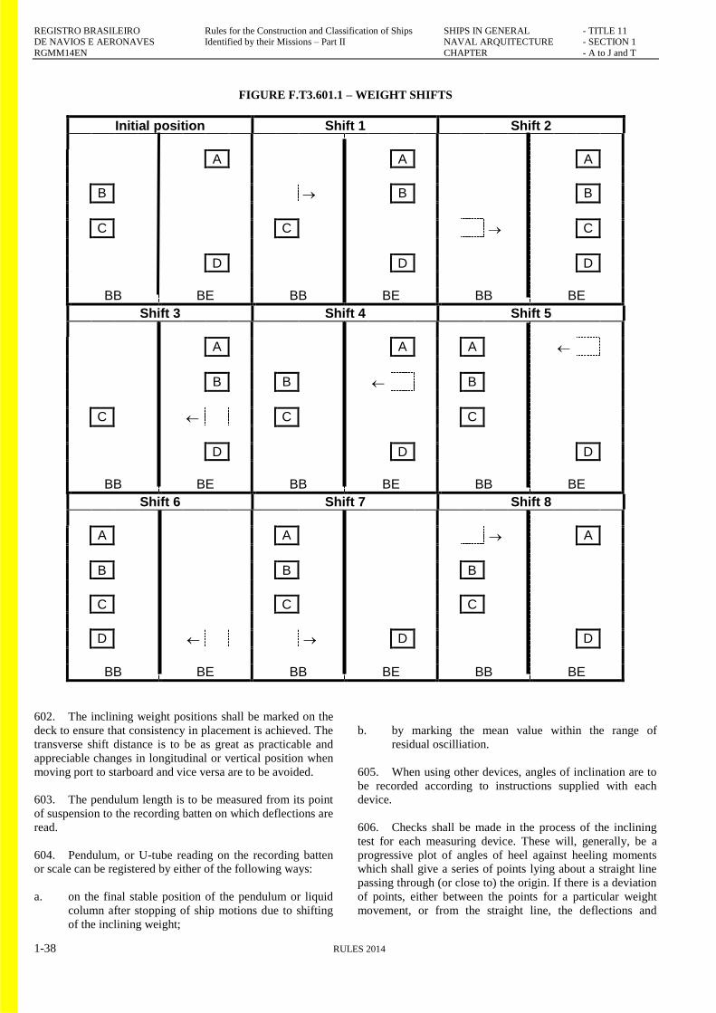
REGISTRO BRASILEIRO Rules for the Construction and Classification of Ships SHIPS IN GENERAL - TITLE 11 DE NAVIOS E AERONAVES Identified by their Missions – Part II NAVAL ARQUITECTURE - SECTION 1
RGMM14EN CHAPTER - A to J and T
1-38 RULES 2014
FIGURE F.T3.601.1 – WEIGHT SHIFTS
Initial position Shift 1 Shift 2
A A A
B B B
C C C
D D D
BB BE BB BE BB BE
Shift 3 Shift 4 Shift 5
A A A
B B B
C C C
D D D
BB BE BB BE BB BE
Shift 6 Shift 7 Shift 8
A A A
B B B
C C C
D D D
BB BE BB BE BB BE
602. The inclining weight positions shall be marked on the
deck to ensure that consistency in placement is achieved. The
transverse shift distance is to be as great as practicable and
appreciable changes in longitudinal or vertical position when
moving port to starboard and vice versa are to be avoided.
603. The pendulum length is to be measured from its point
of suspension to the recording batten on which deflections are
read.
604. Pendulum, or U-tube reading on the recording batten
or scale can be registered by either of the following ways:
a. on the final stable position of the pendulum or liquid
column after stopping of ship motions due to shifting
of the inclining weight;
b. by marking the mean value within the range of
residual oscilliation.
605. When using other devices, angles of inclination are to
be recorded according to instructions supplied with each
device.
606. Checks shall be made in the process of the inclining
test for each measuring device. These will, generally, be a
progressive plot of angles of heel against heeling moments
which shall give a series of points lying about a straight line
passing through (or close to) the origin. If there is a deviation
of points, either between the points for a particular weight
movement, or from the straight line, the deflections and
REGISTRO BRASILEIRO Rules for the Construction and Classification of Ships SHIPS IN GENERAL - TITLE 11
DE NAVIOS E AERONAVES Identified by their Missions – Part II NAVAL ARQUITECTURE - SECTION 1 RGMM14EN CHAPTER - A to J and T
RULES 2014 1-39
moments shall be checked and corrected prior to the next
weight movement.
607. Personnel shall be instructed to remain on their
assigned positions while inclination readings are being taken
and a check shall be made that all mooring lines, etc., remain
slack following each weigh shift until all deflections have
been taken and recorded.
700. Other Relevant Data
701. In the case where the inclinations are carried out by
means of transfer of water, it has to be possible to evaluate
accurately the weight and the centre of the shifted liquid in
relation to the ship's heel and trim.
702. The weather conditions, i.e., wind speed and direction
relative to the vessel, sea state, air and water temperatures,
etc., during the test are to be recorded. If during the course of
an inclining test circumstances arise such that the aforesaid
requirements are not complied with the attending Surveyor
shall advise the Person in Charge that the results may not be
accepted.
800. Test Report and Analysis of Lightship Data
801. The Builder/Owner shall incorporate the data gathered
during the test into a comprehensive test report, which may
be combined with the analysis of the lightship data. Test
readings not used in the final analysis shall still be recorded
in the report.
802. The Surveyor is to ensure that the data given in the
report is consistent with that gathered during the test and to
sign the report.
803. The inclining test report and analysis, combined with
the report or separately, shall be submitted to the RBNA for
review and acceptance of results as the basis for approval of
the stability information of the ship.
Rgmm14en-PIIT11S1-abcdefghijt-00


![Iacs Standard[1]](https://img.pdfslide.net/doc/110x75/54774576b4af9f76108b46d1/iacs-standard1.jpg)