Embed Size (px)
Citation preview
System Tools
CHAPTERS
1. System Tools
2. Admin Setup
3. Management
4. SNMP
5. Diagnostics
6. Time Settings
7. System Log
Configuration Guide 2
System Tools System Tools
This guide applies to:TL-R470T+ v6 or above, TL-R480T+ v9 or above, TL-600VPN v4 or above, TL-ER5120 v3 or above, TL-ER6020 v2 or above, TL-ER6120 v3 or above
1 System Tools
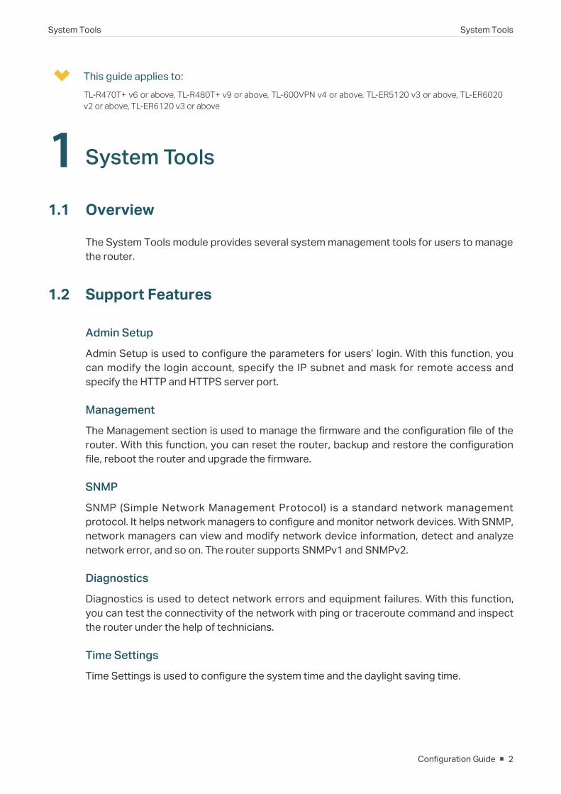
1.1 Overview
The System Tools module provides several system management tools for users to manage the router.
1.2 Support Features
Admin Setup
Admin Setup is used to configure the parameters for users’ login. With this function, you can modify the login account, specify the IP subnet and mask for remote access and specify the HTTP and HTTPS server port.
Management
The Management section is used to manage the firmware and the configuration file of the router. With this function, you can reset the router, backup and restore the configuration file, reboot the router and upgrade the firmware.
SNMP
SNMP (Simple Network Management Protocol) is a standard network management protocol. It helps network managers to configure and monitor network devices. With SNMP, network managers can view and modify network device information, detect and analyze network error, and so on. The router supports SNMPv1 and SNMPv2.
Diagnostics
Diagnostics is used to detect network errors and equipment failures. With this function, you can test the connectivity of the network with ping or traceroute command and inspect the router under the help of technicians.
Time Settings
Time Settings is used to configure the system time and the daylight saving time.

System Tools System Tools
Configuration Guide 3
System Log
System Log is used to view the system log of the router. You can also configure the router to send the log to a server.
Configuration Guide 4
System Tools Admin Setup
2 Admin SetupIn Admin Setup module, you can configure the following features:
Admin Setup
Remote Management
System Settings
2.1 Admin Setup
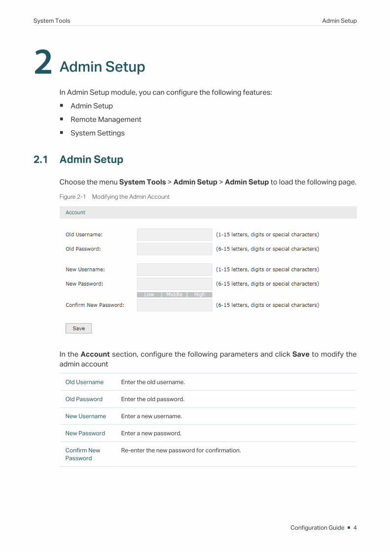
Choose the menu System Tools > Admin Setup > Admin Setup to load the following page.
Figure 2-1 Modifying the Admin Account
In the Account section, configure the following parameters and click Save to modify the admin account
Old Username Enter the old username.
Old Password Enter the old password.
New Username Enter a new username.
New Password Enter a new password.
Confirm New Password
Re-enter the new password for confirmation.
System Tools Admin Setup
Configuration Guide 5
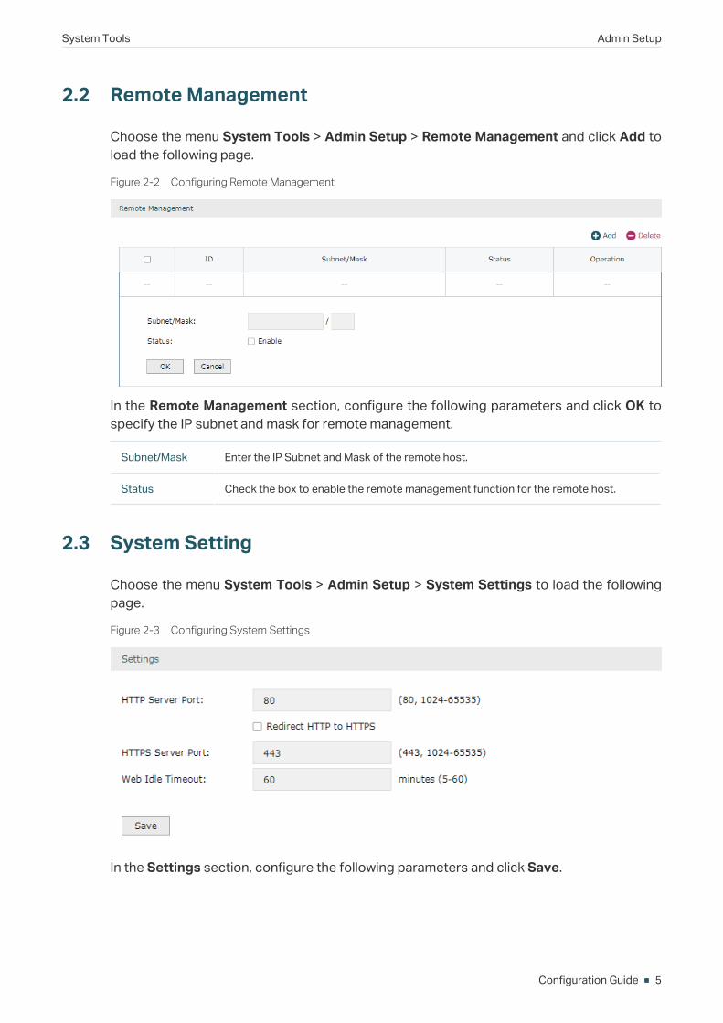
2.2 Remote Management
Choose the menu System Tools > Admin Setup > Remote Management and click Add to load the following page.
Figure 2-2 Configuring Remote Management
In the Remote Management section, configure the following parameters and click OK to specify the IP subnet and mask for remote management.
Subnet/Mask Enter the IP Subnet and Mask of the remote host.
Status Check the box to enable the remote management function for the remote host.
2.3 System Setting
Choose the menu System Tools > Admin Setup > System Settings to load the following page.
Figure 2-3 Configuring System Settings
In the Settings section, configure the following parameters and click Save.
Configuration Guide 6
System Tools Admin Setup
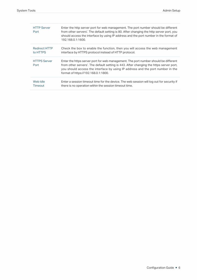
HTTP Server Port
Enter the http server port for web management. The port number should be different from other servers’. The default setting is 80. After changing the http server port, you should access the interface by using IP address and the port number in the format of 192.168.0.1:1600.
Redirect HTTP to HTTPS
Check the box to enable the function, then you will access the web management interface by HTTPS protocol instead of HTTP protocol.
HTTPS Server Port
Enter the https server port for web management. The port number should be different from other servers’. The default setting is 443. After changing the https server port, you should access the interface by using IP address and the port number in the format of https://192.168.0.1:1800.
Web Idle Timeout
Enter a session timeout time for the device. The web session will log out for security if there is no operation within the session timeout time.
System Tools Management
Configuration Guide 7
3 ManagementIn Management module, you can configure the following features:
Factory Default Restore
Backup & Restore
Reboot
Firmware Upgrade
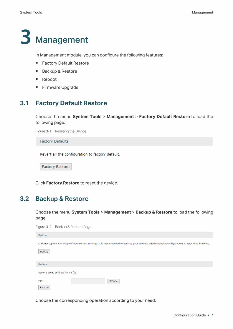
3.1 Factory Default Restore
Choose the menu System Tools > Management > Factory Default Restore to load the following page.
Figure 3-1 Reseting the Device
Click Factory Restore to reset the device.
3.2 Backup & Restore
Choose the menu System Tools > Management > Backup & Restore to load the following page.
Figure 3-2 Backup & Restore Page
Choose the corresponding operation according to your need:
Configuration Guide 8
System Tools Management
1) In the Backup section, click Backup to save your current configuration as a configuration file and export the file to the host.
2) In the Restore section, select one configuration file saved in the host and click Restore to import the saved configuration to your router.
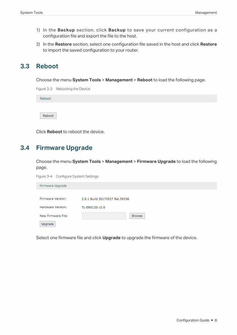
3.3 Reboot
Choose the menu System Tools > Management > Reboot to load the following page.
Figure 3-3 Rebooting the Device
Click Reboot to reboot the device.
3.4 Firmware Upgrade
Choose the menu System Tools > Management > Firmware Upgrade to load the following page.
Figure 3-4 Configure System Settings
Select one firmware file and click Upgrade to upgrade the firmware of the device.
System Tools SNMP
Configuration Guide 9
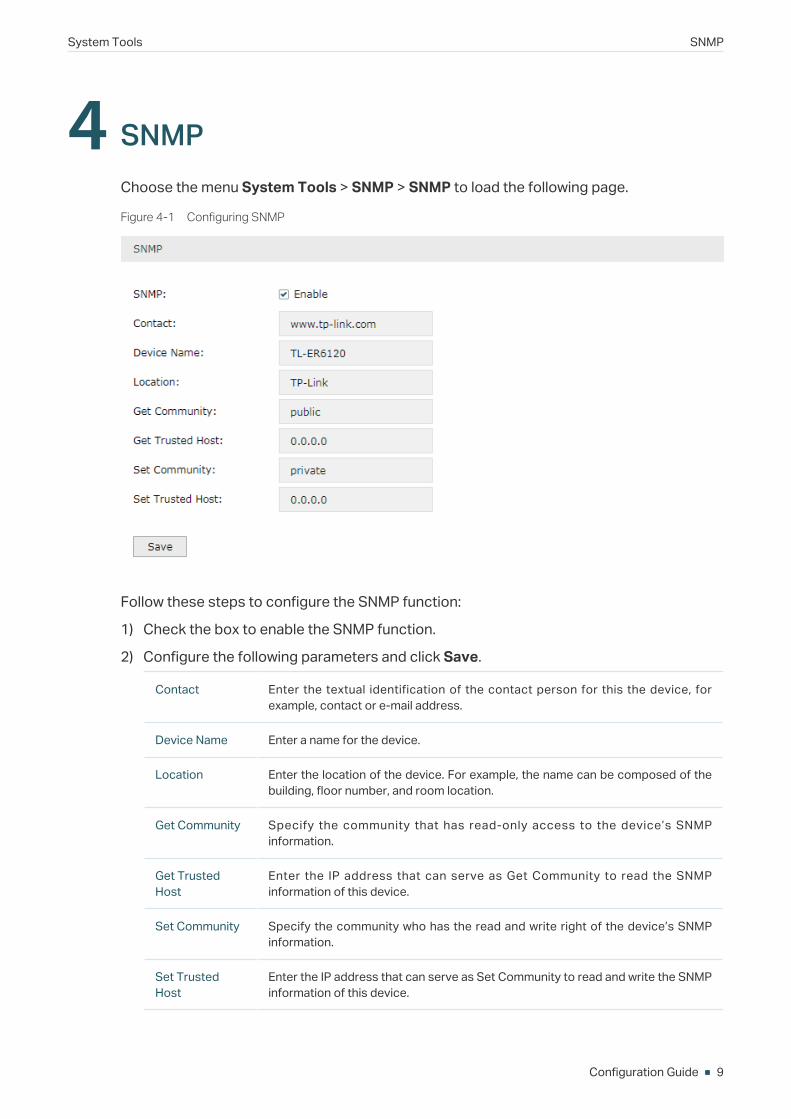
4 SNMPChoose the menu System Tools > SNMP > SNMP to load the following page.
Figure 4-1 Configuring SNMP
Follow these steps to configure the SNMP function:
1) Check the box to enable the SNMP function.
2) Configure the following parameters and click Save.
Contact Enter the textual identification of the contact person for this the device, for example, contact or e-mail address.
Device Name Enter a name for the device.
Location Enter the location of the device. For example, the name can be composed of the building, floor number, and room location.
Get Community Specify the community that has read-only access to the device’s SNMP information.
Get Trusted Host
Enter the IP address that can serve as Get Community to read the SNMP information of this device.
Set Community Specify the community who has the read and write right of the device’s SNMP information.
Set Trusted Host
Enter the IP address that can serve as Set Community to read and write the SNMP information of this device.
Configuration Guide 10
System Tools Diagnostics
5 DiagnosticsIn Diagnostics module, you can configure the following features:
Diagnostics
Remote Assistance
5.1 Diagnostics
Ping and traceroute are both used to test the connectivity between two devices in the network. In addition, ping can show the roundtrip time between the two devices directly and traceroute can show the IP address of routers along the route path.
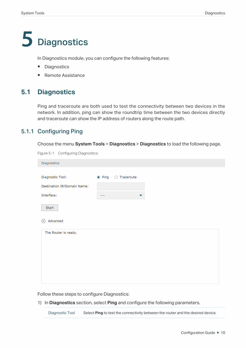
5.1.1 Configuring Ping
Choose the menu System Tools > Diagnostics > Diagnostics to load the following page.
Figure 5-1 Configuring Diagnostics
Follow these steps to configure Diagnostics:
1) In Diagnostics section, select Ping and configure the following parameters.
Diagnostic Tool Select Ping to test the connectivity between the router and the desired device.
System Tools Diagnostics
Configuration Guide 11
Destination IP/Domain Name
Enter the IP address or the domain name that you want to ping or tracert.
Interface Select the interface that sends the detection packets.
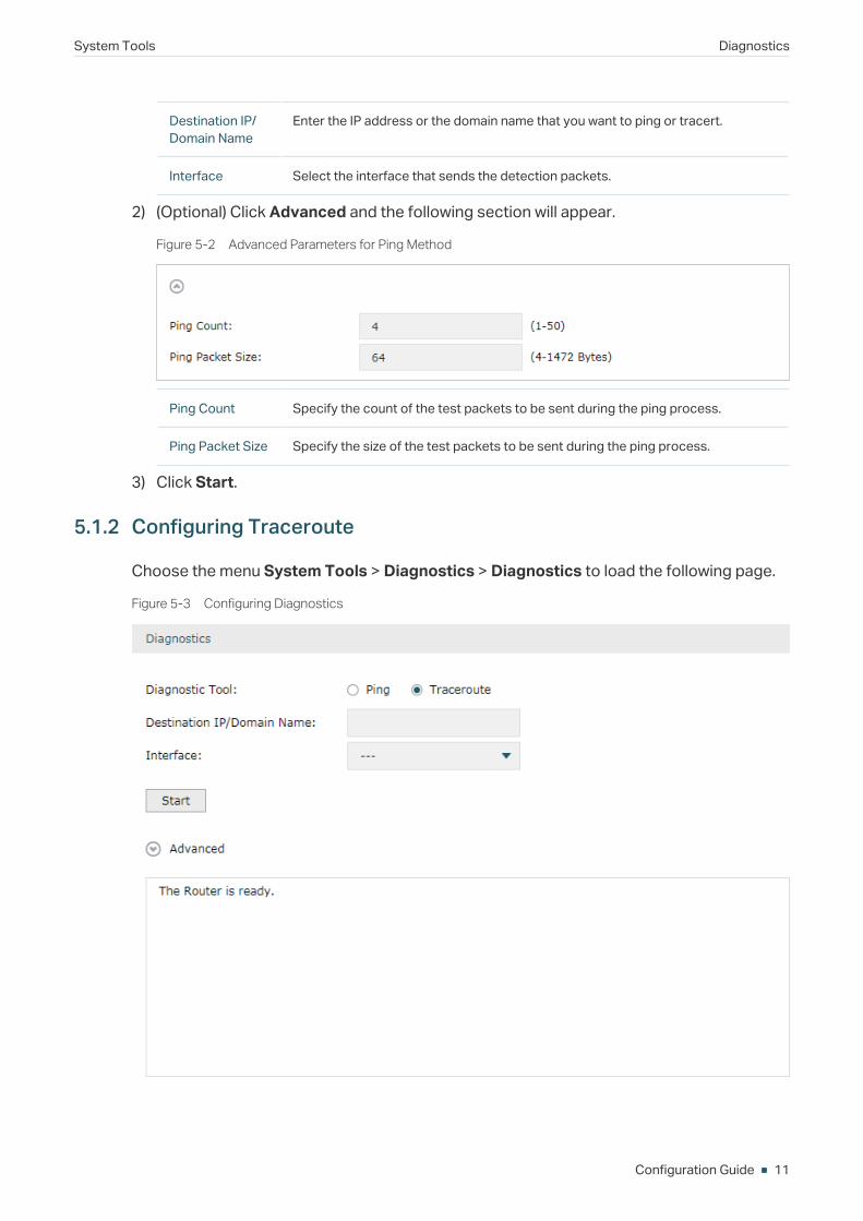
2) (Optional) Click Advanced and the following section will appear.
Figure 5-2 Advanced Parameters for Ping Method
Ping Count Specify the count of the test packets to be sent during the ping process.
Ping Packet Size Specify the size of the test packets to be sent during the ping process.
3) Click Start.
5.1.2 Configuring Traceroute
Choose the menu System Tools > Diagnostics > Diagnostics to load the following page.
Figure 5-3 Configuring Diagnostics

Configuration Guide 12
System Tools Diagnostics
Follow these steps to configure Diagnostics:
1) In Diagnostics section, select Traceroute and configure the following parameters.
Diagnostic Tool Select Traceroute to test the connectivity between the router and the desired device.
Destination IP/Domain Name
Enter the IP address or the domain name that you want to ping or tracert.
Interface Select the interface that sends the detection packets.
2) (Optional) Click Advanced and the following section will appear.
Figure 5-4 Advanced Parameters for Traceroute Method
Traceroute MAX TTL
Specify the traceroute max TTL (Time To Live) during the traceroute process. It is the maximum number of the route hops the test packets can pass through.
3) Click Start.
5.2 Remote Assistance
Note:Please make contact with the technicians brfore trying to use this function.
Choose the menu System Tools > Diagnostics > Remote Assistance to load the following page.
Figure 5-5 Remote Assistance Page
1) In the Remote Assistance section, check the box and click Save to enable the remote assistance function and then the technicians can access your router and help to solve the problems by SSH.

System Tools Diagnostics
Configuration Guide 13
2) In the Diagnostic Information section, click Export to download a binary (.bin) file containing helpful information, and send it to the technicians for help.
Configuration Guide 14
System Tools Time Settings
6 Time SettingsIn Time Settings module, you can configure the following features:
System Time
Daylight Saving Time
6.1 Setting the System Time
Choose one method to set the system time.
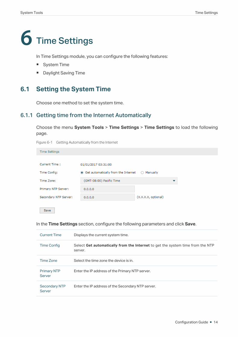
6.1.1 Getting time from the Internet Automatically
Choose the menu System Tools > Time Settings > Time Settings to load the following page.
Figure 6-1 Getting Automatically from the Internet
In the Time Settings section, configure the following parameters and click Save.
Current Time Displays the current system time.
Time Config Select Get automatically from the Internet to get the system time from the NTP server.
Time Zone Select the time zone the device is in.
Primary NTP Server
Enter the IP address of the Primary NTP server.
Secondary NTP Server
Enter the IP address of the Secondary NTP server.
System Tools Time Settings
Configuration Guide 15
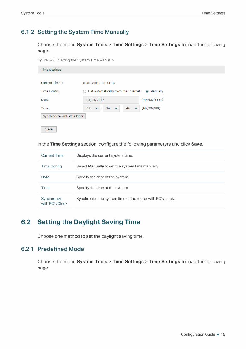
6.1.2 Setting the System Time Manually
Choose the menu System Tools > Time Settings > Time Settings to load the following page.
Figure 6-2 Setting the System Time Manually
In the Time Settings section, configure the following parameters and click Save.
Current Time Displays the current system time.
Time Config Select Manually to set the system time manually.
Date Specify the date of the system.
Time Specify the time of the system.
Synchronize with PC’s Clock
Synchronize the system time of the router with PC’s clock.
6.2 Setting the Daylight Saving Time
Choose one method to set the daylight saving time.
6.2.1 Predefined Mode
Choose the menu System Tools > Time Settings > Time Settings to load the following page.
Configuration Guide 16
System Tools Time Settings
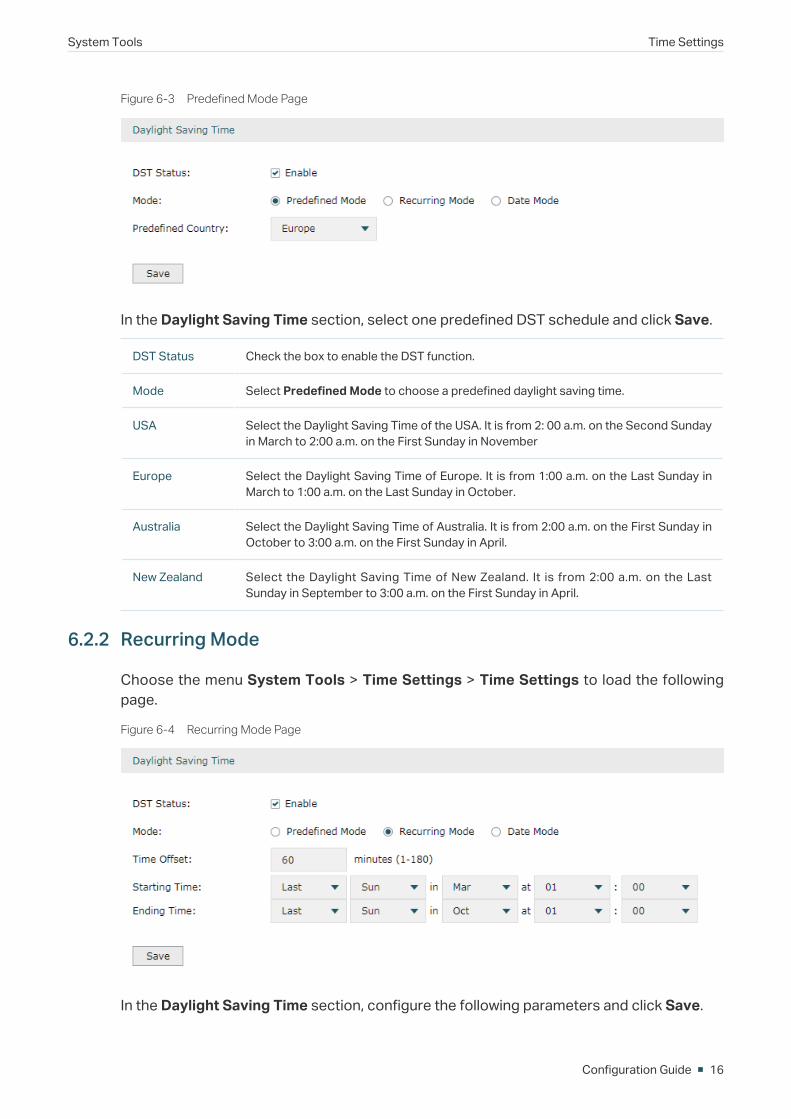
Figure 6-3 Predefined Mode Page
In the Daylight Saving Time section, select one predefined DST schedule and click Save.
DST Status Check the box to enable the DST function.
Mode Select Predefined Mode to choose a predefined daylight saving time.
USA Select the Daylight Saving Time of the USA. It is from 2: 00 a.m. on the Second Sunday in March to 2:00 a.m. on the First Sunday in November
Europe Select the Daylight Saving Time of Europe. It is from 1:00 a.m. on the Last Sunday in March to 1:00 a.m. on the Last Sunday in October.
Australia Select the Daylight Saving Time of Australia. It is from 2:00 a.m. on the First Sunday in October to 3:00 a.m. on the First Sunday in April.
New Zealand Select the Daylight Saving Time of New Zealand. It is from 2:00 a.m. on the Last Sunday in September to 3:00 a.m. on the First Sunday in April.
6.2.2 Recurring Mode
Choose the menu System Tools > Time Settings > Time Settings to load the following page.
Figure 6-4 Recurring Mode Page
In the Daylight Saving Time section, configure the following parameters and click Save.
System Tools Time Settings
Configuration Guide 17
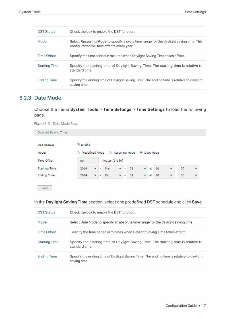
DST Status Check the box to enable the DST function.
Mode Select Recurring Mode to specify a cycle time range for the daylight saving time. This configuration will take effects every year.
Time Offset Specify the time added in minutes when Daylight Saving Time takes effect.
Starting Time Specify the starting time of Daylight Saving Time. The starting time is relative to standard time.
Ending Time Specify the ending time of Daylight Saving Time. The ending time is relative to daylight saving time.
6.2.3 Date Mode
Choose the menu System Tools > Time Settings > Time Settings to load the following page.
Figure 6-5 Date Mode Page
In the Daylight Saving Time section, select one predefined DST schedule and click Save.
DST Status Check the box to enable the DST function.
Mode Select Date Mode to specify an absolute time range for the daylight saving time.
Time Offset Specify the time added in minutes when Daylight Saving Time takes effect.
Starting Time Specify the starting time of Daylight Saving Time. The starting time is relative to standard time.
Ending Time Specify the ending time of Daylight Saving Time. The ending time is relative to daylight saving time.
Configuration Guide 18
System Tools System Log
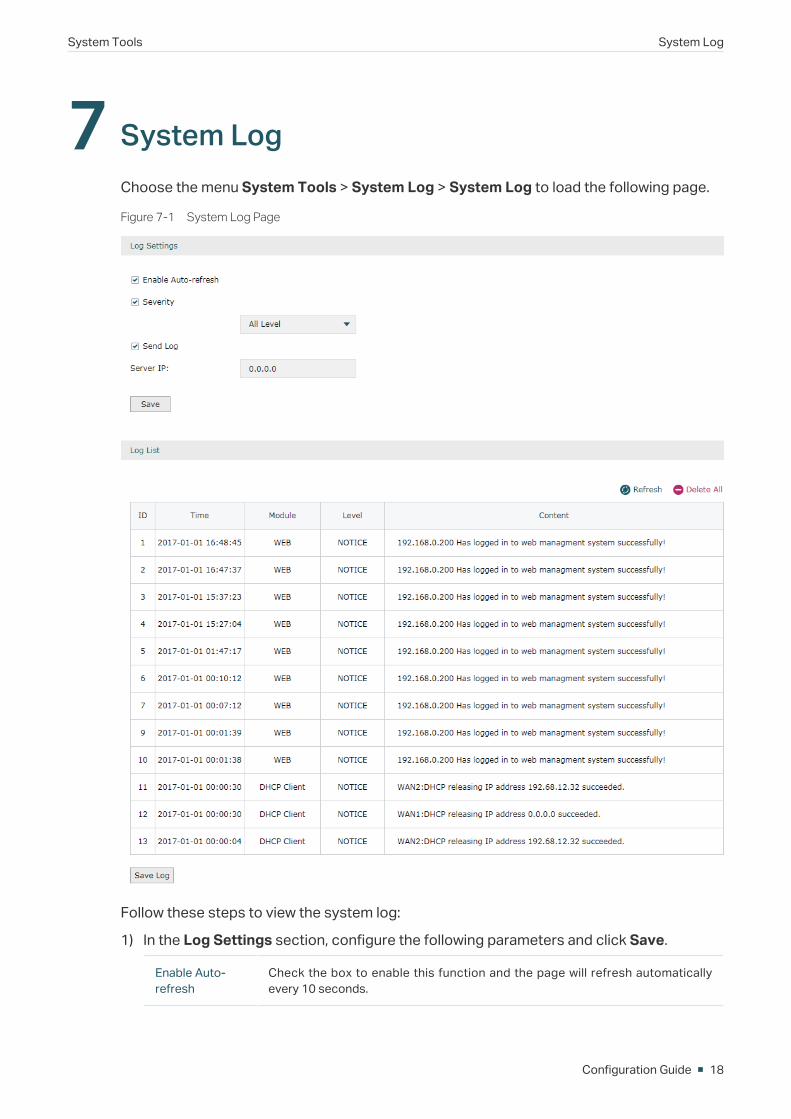
7 System LogChoose the menu System Tools > System Log > System Log to load the following page.
Figure 7-1 System Log Page
Follow these steps to view the system log:
1) In the Log Settings section, configure the following parameters and click Save.
Enable Auto-refresh
Check the box to enable this function and the page will refresh automatically every 10 seconds.
System Tools System Log
Configuration Guide 19
Severity Enable Severity and specify the importance of the logs you want to view in the log list.
ALL Level: Logs of all levels.
EMERGENCY: Errors that render the router unusable, such as hardware errors.
ALERT: Errors that must be resolved immediately, such as flash write errors.
CRITICAL: Errors that put the system at risk, such as a failure to release memory.
ERROR: Generic errors.
WARNING: Warning messages, such as WinNuke attack warnings.
NOTICE: Important notifications, such as IKE policy mismatches.
INFO: Informational messages.
DEBUG: Debug-level notifications, such as when the router receives a DNS packet.
Send Log Enable the Send Log function and then the newly generated logs will be sent to the specified server.
Server IP Specify the IP address of the server that the logs will be sent to.
2) (Optional) Click Save Log to save the current logs to the host.