Embed Size (px)
Citation preview
Vol-1 Issue-5 2015 IJARIIE-ISSN(O)-2395-4396
1392 www.ijariie.com 72
Characterization CompareProcesses and
Parameter of SS304 between Nitriding and Thin
FilmDepositionofTiNby Reactive Magnetron
Sputtering
Mohd Aslam1, Dr. Satpal Sharma
2, Mohd Usman Ahmad
3, Anam Parveen
4
1Intt. M.tech Mechanical, Mechanical Department, Gautam Budha University, U.P., India201308
2Assistant professor, Head Of MechanicalDepartment, Gautam Budha University, U.P., India201308
3Intt. M.tech Mechanical, Mechanical Department, Gautam Budha University, U.P., India201308
4Intt.Biotech, Biotech Department, Gautam Budha University, U.P., India201308
ABSTRACT
From last few decades we are using thin film coating and nitriding for the improvement of surface modification.
This is also improving mechanical properties wear, corrosion and improving service life of the material, Nitriding is
improve hardness of the material fromsurface to some depth and ultimately increase toughness, hardness and also
Improve wear resistant of the material and increases productivity. Coating gives different different color depend on
the what will be used target for the coating like TiN gives gold color, here we are using two Ti target and flow of
reacting gas is Nitrogen . The TiN coating is improving hardness up to 24 Nano-meter thickness will the 1 to 7µ
depend on time of experiment and substrate temperature. The uses of TiN thin film coating in universal use, coating
on the tool material, forming like molds and dies and also uses for the decorating purpose.
We are using Ti Target and reactive magnetron sputtering process for the coating of TiN on the substrate material
SS304 and also for the nitriding H2 gas uses for the flushing and H2+N2 gas uses for the nitriding at a certain
temperature and pressure inside a vacuum chamber. Here we are characterizing MicrohardnessTest, X-Ray
Deposition, and Energy (XRD)Dispersive Spectroscopy (EDS) Field Emission Scanning Electron Microscopy
(FESEM).
The purpose and conclusion of various analysis’s is that improve the hardness, corrosion, wear resistance and
toughness of the material ss304 by using of reactive magnetron sputtering (RMS) and Nitriding process.
Keyword: -RMSP1, Coating2, Nitriding3, EDX4, XRD5, Microhardness Test6
1.1 INTRODUCTION
For the hard coating of material we are using many techniquesas shown in figure (1)[1]
below but we are using
reactive magnetron sputtering process. This is the classification of physical vapour deposition (PVD) technique.
According to reactive magnetron sputtering process we are using Magnet of wheel on both side which have 1000
gauss on both side but at center where coating isperformed on the substrate sample it has to occurs nearly 300 gauss
.The TiN coating uses for the commercial purpose for forming and decorating purpose, it has golden color so nice in
looking and hard so we are using in many application like thermal barrier coating, cutting tool, watches.
So overall cutting performance and tooling life is increases and Cr-based coating are using for the industrial tools.[2]
According to TiN coating we use two Ti target and substrate material SS304 by applying the process reactive
Vol-1 Issue-5 2015 IJARIIE-ISSN(O)-2395-4396
1392 www.ijariie.com 73
magnetron techniques at the certain gases flow rate Ar and N2under a certain temperature and pressure we are
performing TiN coting and details described in the experimental work.
1.2Nitriding is a heat treating process that N2 diffuses into the surface of metal. [3]
Initially material polishing process
of nitriding is same as the thin film coating of TiN. Nitriding is done at high temperature as compare to thin film
coating by reactive magnetron sputtering and nitriding is done at high pressure as compare to TiN coating by
reactive magnetron sputtering .In a case of nitriding diffusion pump is not required but in TiN coating diffusion
pump is required because it has to coating occurs at low pressure in 4×10⁻³
to 1×10⁻²
mbar. In the nitriding is
hardness is obtained but in TiN coating occurs a thin layer 1 to 7 µ depend on time and flow rate of gasses. Plasma
nitriding also known as ion, plasma ion, and glow discharge nitriding it is an surface hardening treatment for
metallic materials hard layer to protect the metal.[4]
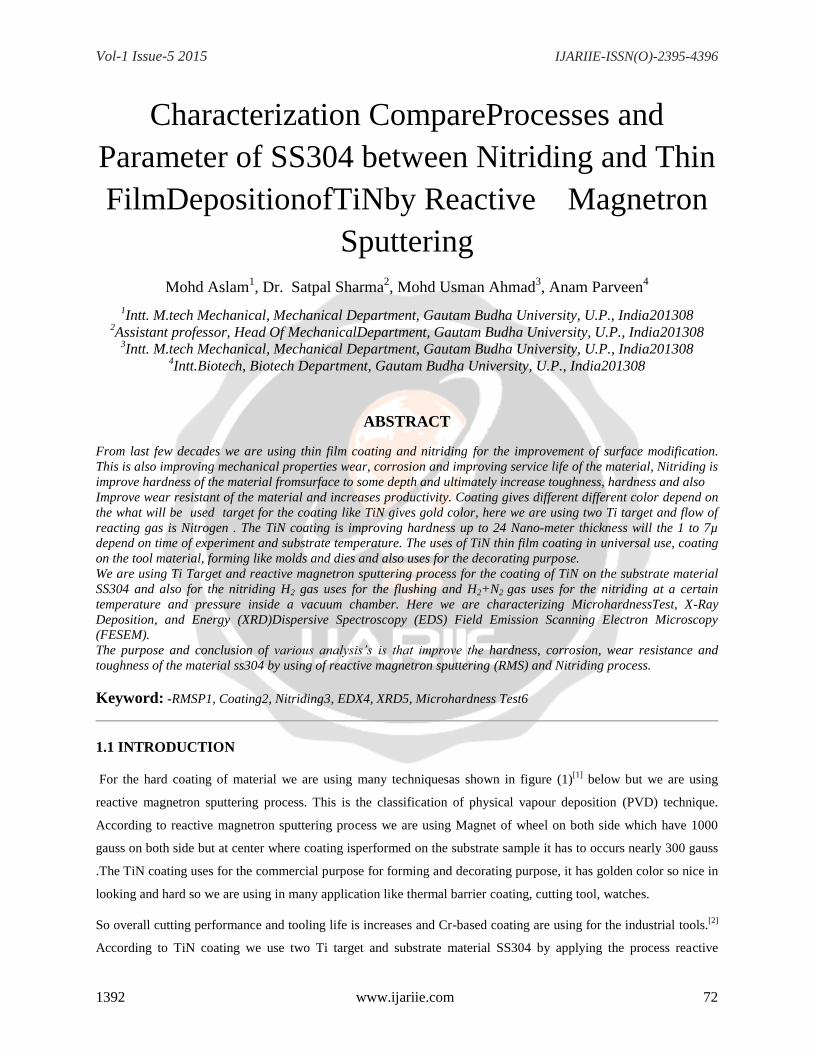
Classification of nitriding described below as shown in the figure
in figure 2.
Gas Nitriding processes
Sat Bath Nitriding
Plasma, Ion Nitriding
Fig 1 Classifications of Hard Coating Techniques Fig 2 Classification of Nitriding
In the above figure we are only focused on the reactive magnetron sputtering process as given in the hard coating
technique’s and process. Also in figure2 nitriding is process diffuse nitrogen in to the surface of the metal under a
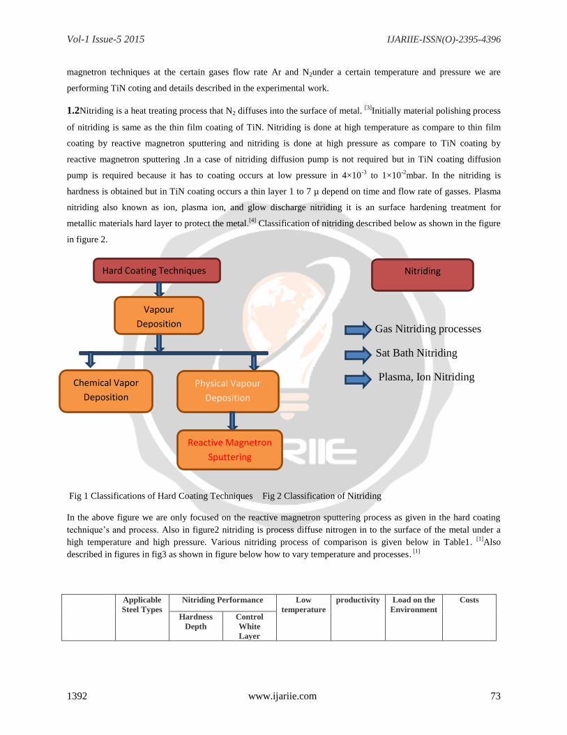
high temperature and high pressure. Various nitriding process of comparison is given below in Table1. [1]
Also
described in figures in fig3 as shown in figure below how to vary temperature and processes. [1]
Applicable
Steel Types
Nitriding Performance Low
temperature
productivity Load on the
Environment
Costs
Hardness
Depth
Control
White
Layer
Hard Coating Techniques
Vapour
Deposition
Chemical Vapor
Deposition
Physical Vapour
Deposition
Reactive Magnetron
Sputtering
Nitriding
Vol-1 Issue-5 2015 IJARIIE-ISSN(O)-2395-4396
1392 www.ijariie.com 74
Gas
Nitriding
×
Carbon steel
Alloy steel
× Significantly
affected by
surface
properties
× Nitriding
capability is
low and it is
difficult to
control the
white layer
× Difficult
Mass-
producibility
is good and
internal
production
is possible
Salt Bath
Nitriding
Carbon steel
Low and
high alloy
steels
Stainless
steel
Cast iron
Significantly
affected by
shape and
salt bath
×
Batch-by-
batch
adjustment
is
impossible
Possible to a
certain
extent
×
Mass-
producibility
is good but
internal
production
is very
difficult
Ion
Nitriding
Carbon steel
Low and
high alloy
steels
Stainless
steel
Cast iron
Significantly
affected by
shape of
workpiece
Controllable
to a certain
extent
Possible
×
Low
× Mass-
producibility
is not good
Table 1 Comparison of Various Nitriding Processes
Heating Pattern and Treatment Process during Nitriding
Fig 3 Heating Pattern and Treatment Process
1.3 REACTIVE MAGNETRON SPUTTERING
In the reacting magnetron sputtering process we are sing two titanium (Ti) target which have 60 mm diameter and
10 mm thickness and substrate material (Sample) have 20 mm diameter ,8 mm thickness .Flow of gasses are N2 and
Ar where N2 use as a reacting gas and Ar use for flushing and for the sputtering. During coating working pressure is
in range of 10-3
mbar pressure if pressure is between 4×10⁻³
to 1×10⁻²
mbar then it will gives best coating, And
temperature varying in respect to what will be voltage and current provide. Generally voltage and current in between
Temp.OC
500
400
300 Low temperature nitriding
Cooling
NV Nitriding NH3
NH3+RX
Activated
treatment Temp. boosting 1
NV Nitriding
Gas Salt Bath Nitriding
Vol-1 Issue-5 2015 IJARIIE-ISSN(O)-2395-4396
1392 www.ijariie.com 75
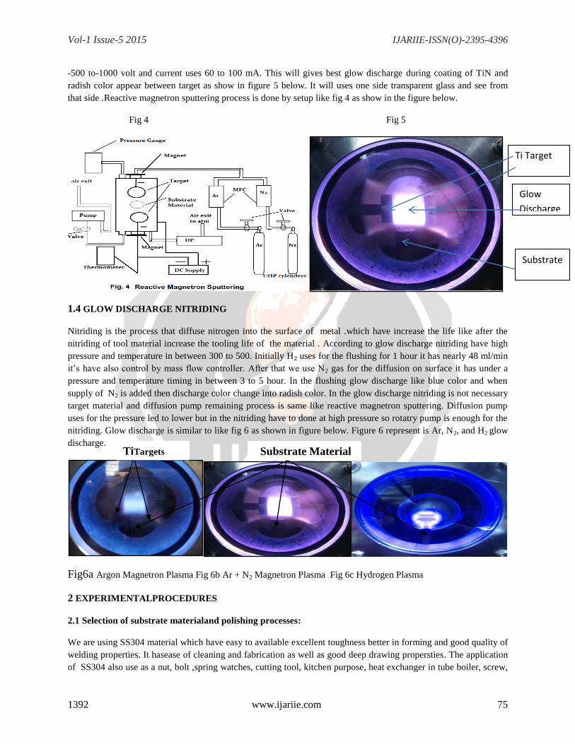
-500 to-1000 volt and current uses 60 to 100 mA. This will gives best glow discharge during coating of TiN and
radish color appear between target as show in figure 5 below. It will uses one side transparent glass and see from
that side .Reactive magnetron sputtering process is done by setup like fig 4 as show in the figure below.
Fig 4 Fig 5
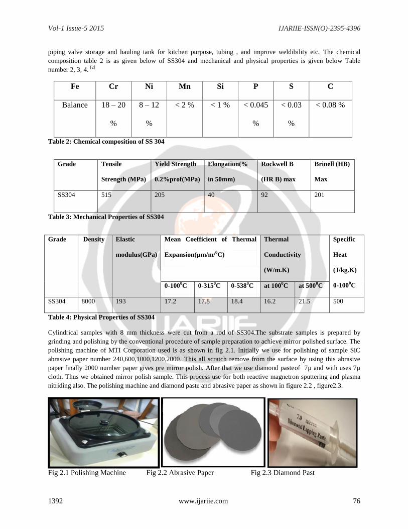
1.4 GLOW DISCHARGE NITRIDING
Nitriding is the process that diffuse nitrogen into the surface of metal .which have increase the life like after the
nitriding of tool material increase the tooling life of the material . According to glow discharge nitriding have high
pressure and temperature in between 300 to 500. Initially H2 uses for the flushing for 1 hour it has nearly 48 ml/min
it’s have also control by mass flow controller. After that we use N2 gas for the diffusion on surface it has under a
pressure and temperature timing in between 3 to 5 hour. In the flushing glow discharge like blue color and when
supply of N2 is added then discharge color change into radish color. In the glow discharge nitriding is not necessary
target material and diffusion pump remaining process is same like reactive magnetron sputtering. Diffusion pump
uses for the pressure led to lower but in the nitriding have to done at high pressure so rotatry pump is enough for the
nitriding. Glow discharge is similar to like fig 6 as shown in figure below. Figure 6 represent is Ar, N2, and H2 glow
discharge.
Fig6a Argon Magnetron Plasma Fig 6b Ar + N2 Magnetron Plasma Fig 6c Hydrogen Plasma
2 EXPERIMENTALPROCEDURES
2.1 Selection of substrate materialand polishing processes:
We are using SS304 material which have easy to available excellent toughness better in forming and good quality of
welding properties. It hasease of cleaning and fabrication as well as good deep drawing propersties. The application
of SS304 also use as a nut, bolt ,spring watches, cutting tool, kitchen purpose, heat exchanger in tube boiler, screw,
Substrate
Ti Target
Glow
Discharge
TiTargets
Substrate Material
Vol-1 Issue-5 2015 IJARIIE-ISSN(O)-2395-4396
1392 www.ijariie.com 76
piping valve storage and hauling tank for kitchen purpose, tubing , and improve weldibility etc. The chemical
composition table 2 is as given below of SS304 and mechanical and physical properties is given below Table
number 2, 3, 4. [2]
Fe Cr Ni Mn Si P S C
Balance 18 – 20
%
8 – 12
%
< 2 % < 1 % < 0.045
%
< 0.03
%
< 0.08 %
Table 2: Chemical composition of SS 304
Grade Tensile
Strength (MPa)
Yield Strength
0.2%prof(MPa)
Elongation(%
in 50mm)
Rockwell B
(HR B) max
Brinell (HB)
Max
SS304 515 205 40 92 201
Table 3: Mechanical Properties of SS304
Grade Density Elastic
modulus(GPa)
Mean Coefficient of Thermal
Expansion(µm/m/0C)
Thermal
Conductivity
(W/m.K)
Specific
Heat
(J/kg.K)
0-1000C 0-100
0C 0-315
0C 0-538
0C at 100
0C at 500
0C
SS304 8000 193 17.2 17.8 18.4 16.2 21.5 500
Table 4: Physical Properties of SS304
Cylindrical samples with 8 mm thickness were cut from a rod of SS304.The substrate samples is prepared by
grinding and polishing by the conventional procedure of sample preparation to achieve mirror polished surface. The
polishing machine of MTI Corporation used is as shown in fig 2.1. Initially we use for polishing of sample SiC
abrasive paper number 240,600,1000,1200,2000. This all scratch remove from the surface by using this abrasive
paper finally 2000 number paper gives pre mirror polish. After that we use diamond pasteof 7µ and with uses 7µ
cloth. Thus we obtained mirror polish sample. This process use for both reactive magnetron sputtering and plasma
nitriding also. The polishing machine and diamond paste and abrasive paper as shown in figure 2.2 , figure2.3.
Fig 2.1 Polishing Machine Fig 2.2 Abrasive Paper Fig 2.3 Diamond Past
Vol-1 Issue-5 2015 IJARIIE-ISSN(O)-2395-4396
1392 www.ijariie.com 77
According toprocess above figure we use polishing machine abrasive paper and diamond paste figure 2.4.
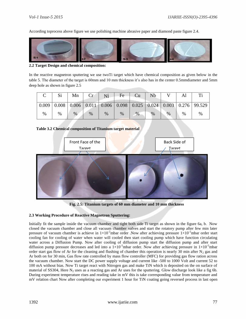
2.2 Target Design and chemical composition:
In the reactive magnetron sputtering we use twoTi target which have chemical composition as given below in the
table 5. The diameter of the target is 60mm and 10 mm thickness it’s also has in the center 0.5mmdiameter and 5mm
deep hole as shown in figure 2.5
C Si Mn Cr Ni Fe Cu Nb V Al Ti
0.009
%
0.008
%
0.006
%
0.011
%
0.006
%
0.098
%
0.025
%
0.024
%
0.003
%
0.276
%
99.529
%
Table 3.2 Chemical composition of Titanium target material
Fig. 2.5: Titanium targets of 60 mm diameter and 10 mm thickness
2.3 Working Procedure of Reactive Magnetron Sputtering:
Initially fit the sample inside the vacuum chamber and tight both side Ti target as shown in the figure 6a, b. Now
closed the vacuum chamber and close all vacuum chamber valves and start the rotatory pump after few min later
pressure of vacuum chamber is achieve in 1×10⁻²
mbar order .Now after achieving pressure 1×10⁻²
mbar order start
cooling fan for cooling of water when water will cooled then start cooling pump which have function circulating
water across a Diffusion Pump. Now after cooling of diffusion pump start the diffusion pump and after start
diffusion pump pressure decreases and led into a 1×10⁻⁵
mbar order. Now after achieving pressure in 1×10⁻⁵
mbar
order start gas flow of Ar for the cleaning and flushing of chamber this operation is nearly 30 min after N2 gas and
Ar both on for 30 min, Gas flow rate controlled by mass flow controller (MFC) for providing gas flow ration across
the vacuum chamber. Now start the DC power supply voltage and current like -500 to 1000 Volt and current 52 to
100 mA without bias. Now Ti target react with Nitrogen gas and make TiN which is deposited on the on surface of
material of SS304, Here N2 uses as a reacting gas and Ar uses for the sputtering. Glow discharge look like a fig 6b.
During experiment temperature rises and reading take in mV this is take corresponding value from temperature and
mV relation chart Now after completing our experiment 1 hour for TiN coating going reversed process in last open
Front Face of the
Target
Back Side of
Target
Vol-1 Issue-5 2015 IJARIIE-ISSN(O)-2395-4396
1392 www.ijariie.com 78
chamber and clean target ,chamber by Petroleum Ether .after that continue our next experiment. As mentioned in
figure below in 2.6 is complete processes.
Fig 2.6 Reactive Magnetron Sputtering
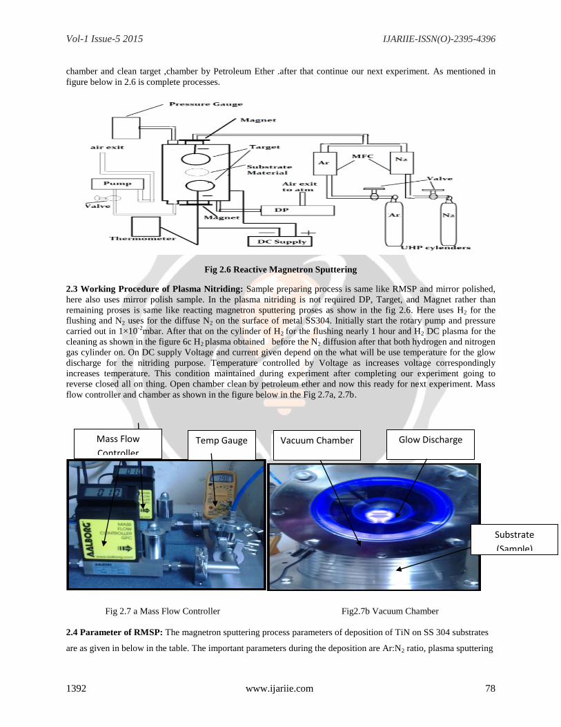
2.3 Working Procedure of Plasma Nitriding: Sample preparing process is same like RMSP and mirror polished,
here also uses mirror polish sample. In the plasma nitriding is not required DP, Target, and Magnet rather than
remaining proses is same like reacting magnetron sputtering proses as show in the fig 2.6. Here uses H2 for the
flushing and N2 uses for the diffuse N2 on the surface of metal SS304. Initially start the rotary pump and pressure
carried out in 1×10⁻²
mbar. After that on the cylinder of H2 for the flushing nearly 1 hour and H2 DC plasma for the
cleaning as shown in the figure 6c H2 plasma obtained before the N2 diffusion after that both hydrogen and nitrogen
gas cylinder on. On DC supply Voltage and current given depend on the what will be use temperature for the glow
discharge for the nitriding purpose. Temperature controlled by Voltage as increases voltage correspondingly
increases temperature. This condition maintained during experiment after completing our experiment going to
reverse closed all on thing. Open chamber clean by petroleum ether and now this ready for next experiment. Mass
flow controller and chamber as shown in the figure below in the Fig 2.7a, 2.7b.
Fig 2.7 a Mass Flow Controller Fig2.7b Vacuum Chamber
2.4 Parameter of RMSP: The magnetron sputtering process parameters of deposition of TiN on SS 304 substrates
are as given in below in the table. The important parameters during the deposition are Ar:N2 ratio, plasma sputtering
Mass Flow
Controller
Vacuum Chamber
Substrate
(Sample)
Glow Discharge Temp Gauge
Vol-1 Issue-5 2015 IJARIIE-ISSN(O)-2395-4396
1392 www.ijariie.com 79
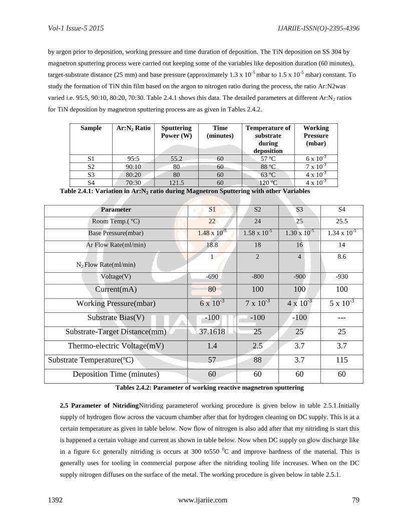
by argon prior to deposition, working pressure and time duration of deposition. The TiN deposition on SS 304 by
magnetron sputtering process were carried out keeping some of the variables like deposition duration (60 minutes),
target-substrate distance (25 mm) and base pressure (approximately 1.3 x 10⁻⁵
mbar to 1.5 x 10⁻⁵
mbar) constant. To
study the formation of TiN thin film based on the argon to nitrogen ratio during the process, the ratio Ar:N2was
varied i.e. 95:5, 90:10, 80:20, 70:30. Table 2.4.1 shows this data. The detailed parameters at different Ar:N2 ratios
for TiN deposition by magnetron sputtering process are as given in Tables 2.4.2.
Sample Ar:N2 Ratio Sputtering
Power (W)
Time
(minutes)
Temperature of
substrate
during
deposition
Working
Pressure
(mbar)
S1 95:5 55.2 60 57 ºC 6 x 10⁻³
S2 90:10 80 60 88 ºC 7 x 10⁻³
S3 80:20 80 60 63 ºC 4 x 10⁻³
S4 70:30 121.5 60 120 ºC 4 x 10⁻³
Table 2.4.1: Variation in Ar:N2 ratio during Magnetron Sputtering with other Variables
Parameter S1 S2 S3 S4
Room Temp.( ºC) 22 24 25 25.5
Base Pressure(mbar) 1.48 x 10⁻⁵
1.58 x 10⁻⁵
1.30 x 10⁻⁵
1.34 x 10⁻⁵
Ar Flow Rate(ml/min) 18.8 18 16 14
N2 Flow Rate(ml/min)
1 2 4 8.6
Voltage(V) -690 -800 -900 -930
Current(mA) 80 100 100 100
Working Pressure(mbar) 6 x 10⁻³
7 x 10⁻³
4 x 10⁻³
5 x 10⁻³
Substrate Bias(V) -100 -100 -100 ---
Substrate-Target Distance(mm) 37.1618 25 25 25
Thermo-electric Voltage(mV) 1.4 2.5 3.7 3.7
Substrate Temperature(ºC) 57 88 3.7 115
Deposition Time (minutes) 60 60 60 60
Tables 2.4.2: Parameter of working reactive magnetron sputtering
2.5 Parameter of NitridingNitriding parameterof working procedure is given below in table 2.5.1.Initially
supply of hydrogen flow across the vacuum chamber after that for hydrogen cleaning on DC supply. This is at a
certain temperature as given in table below. Now flow of nitrogen is also add after that my nitriding is start this
is happened a certain voltage and current as shown in table below. Now when DC supply on glow discharge like
in a figure 6.c generally nitriding is occurs at 300 to550 0C and improve hardness of the material. This is
generally uses for tooling in commercial purpose after the nitriding tooling life increases. When on the DC
supply nitrogen diffuses on the surface of the metal. The working procedure is given below in table 2.5.1.
Vol-1 Issue-5 2015 IJARIIE-ISSN(O)-2395-4396
1392 www.ijariie.com 80
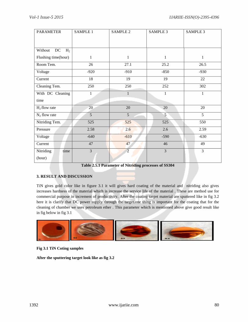
PARAMETER SAMPLE 1 SAMPLE 2 SAMPLE 3 SAMPLE 3
Without DC H2
Flushing time(hour)
1
1
1
1
Room Tem. 26 27.1 25.2 26.5
Voltage -920 -910 -850 -930
Current 18 19 19 22
Cleaning Tem. 250 250 252 302
With DC Cleaning
time
1 1 1 1
H2 flow rate 20 20 20 20
N2 flow rate 5 5 5 5
Nitriding Tem. 525 525 525 550
Pressure 2.58 2.6 2.6 2.59
Voltage -640 -610 -590 -630
Current 47 47 46 49
Nitriding time
(hour)
3 2 3 3
Table 2.5.1 Parameter of Nitriding processes of SS304
3. RESULT AND DISCUSSION
TiN gives gold color like in figure 3.1 it will gives hard coating of the material and nitriding also gives
increases hardness of the material which is increase the service life of the material . These are method use for
commercial purpose in increment of productivity. After the coating target material are sputtered like in fig 3.2
here it is clarify that DC power supply through the target.one thing is important for the coating that for the
cleaning of chamber we uses petroleum ether . This parameter which is mentioned above give good result like
in fig below in fig 3.1
Fig 3.1 TiN Coting samples
After the sputtering target look like as fig 3.2
Vol-1 Issue-5 2015 IJARIIE-ISSN(O)-2395-4396
1392 www.ijariie.com 81
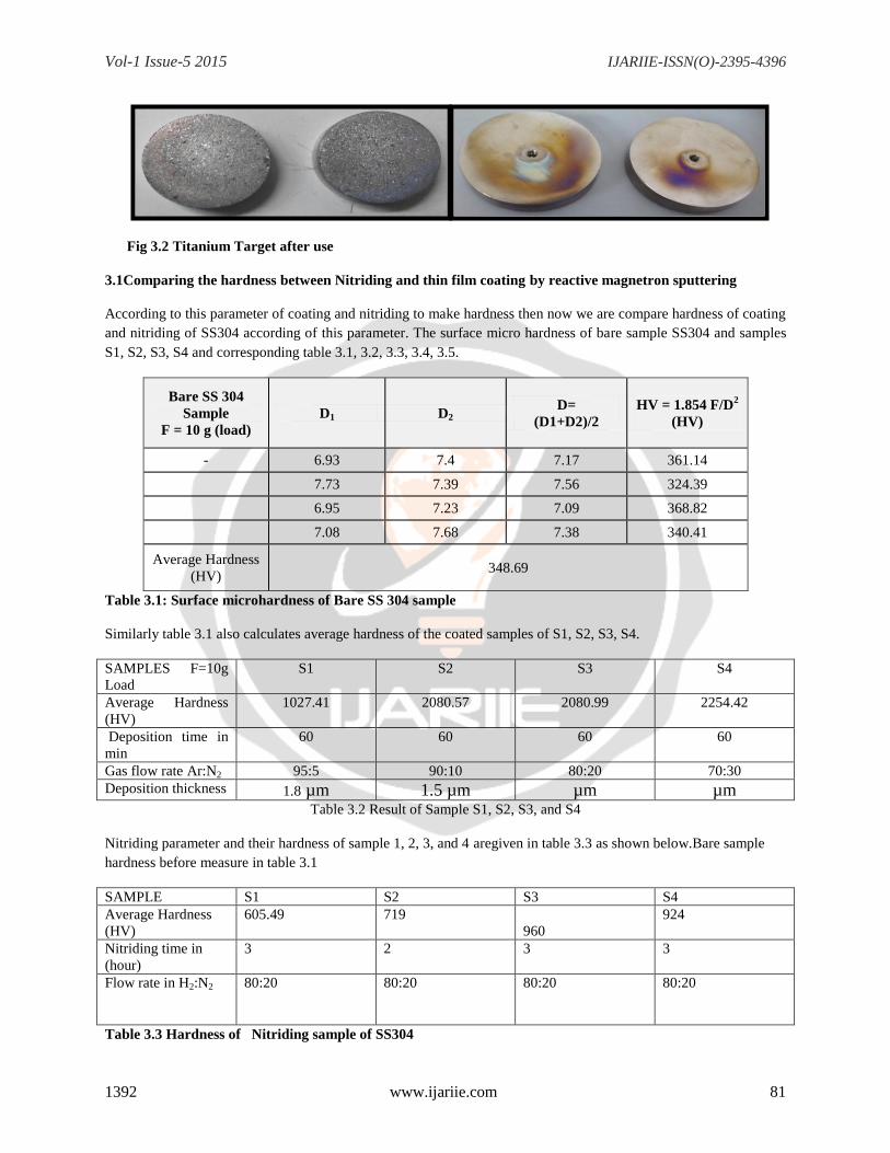
Fig 3.2 Titanium Target after use
3.1Comparing the hardness between Nitriding and thin film coating by reactive magnetron sputtering
According to this parameter of coating and nitriding to make hardness then now we are compare hardness of coating
and nitriding of SS304 according of this parameter. The surface micro hardness of bare sample SS304 and samples
S1, S2, S3, S4 and corresponding table 3.1, 3.2, 3.3, 3.4, 3.5.
Bare SS 304
Sample
F = 10 g (load)
D1 D2 D=
(D1+D2)/2
HV = 1.854 F/D2
(HV)
- 6.93 7.4 7.17 361.14
7.73 7.39 7.56 324.39
6.95 7.23 7.09 368.82
7.08 7.68 7.38 340.41
Average Hardness
(HV) 348.69
Table 3.1: Surface microhardness of Bare SS 304 sample
Similarly table 3.1 also calculates average hardness of the coated samples of S1, S2, S3, S4.
SAMPLES F=10g
Load
S1 S2 S3 S4
Average Hardness
(HV)
1027.41 2080.57 2080.99 2254.42
Deposition time in
min
60 60 60 60
Gas flow rate Ar:N2 95:5 90:10 80:20 70:30
Deposition thickness 1.8 µm 1.5 µm µm µm
Table 3.2 Result of Sample S1, S2, S3, and S4
Nitriding parameter and their hardness of sample 1, 2, 3, and 4 aregiven in table 3.3 as shown below.Bare sample
hardness before measure in table 3.1
SAMPLE S1 S2 S3 S4
Average Hardness
(HV)
605.49 719
960
924
Nitriding time in
(hour)
3 2 3 3
Flow rate in H2:N2 80:20 80:20 80:20 80:20
Table 3.3 Hardness of Nitriding sample of SS304
Vol-1 Issue-5 2015 IJARIIE-ISSN(O)-2395-4396
1392 www.ijariie.com 82
3.2 RESULT ANALYSIS OF HARDNESS NITRIDING AND RMSP: According to these hardness of SS304
after coating and RMSP (Reactive Magnetron Sputtering Processes). When compare hardness then we are obtaining
that reactive magnetron is much harder than nitriding of SS304 according to above table 3.2 and table3.3. We have
obtained best result in RMSP coating so characterize only TiN Film Coating only.
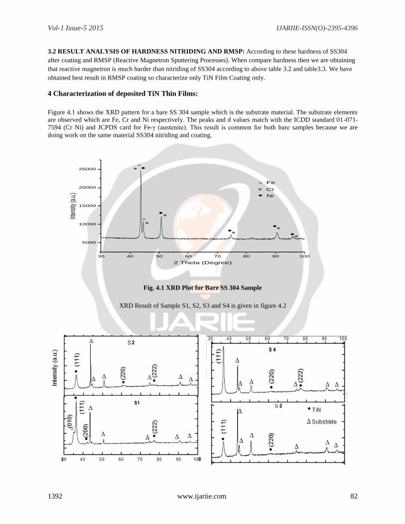
4 Characterization of deposited TiN Thin Films:
Figure 4.1 shows the XRD pattern for a bare SS 304 sample which is the substrate material. The substrate elements
are observed which are Fe, Cr and Ni respectively. The peaks and d values match with the ICDD standard 01-071-
7594 (Cr Ni) and JCPDS card for Fe-γ (austenite). This result is common for both bare samples because we are
doing work on the same material SS304 nitriding and coating.
30 40 50 60 70 80 90 100
5000
10000
15000
20000
25000
Ni
Cr
Int
ensit
y (a.u
.)
2 Theta (Degree)
Fe
Fig. 4.1 XRD Plot for Bare SS 304 Sample
XRD Result of Sample S1, S2, S3 and S4 is given in figure 4.2
Vol-1 Issue-5 2015 IJARIIE-ISSN(O)-2395-4396
1392 www.ijariie.com 83
Fig 4.2 XRD Graph Of Sample S1, S2, S3 and S4 between angle 2 theta and intensity remaining
parameter is given above.
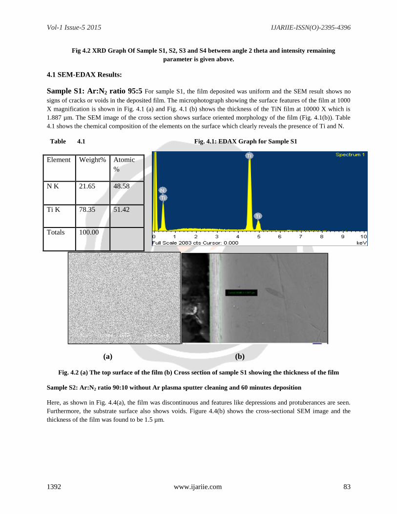
4.1 SEM-EDAX Results:
Sample S1: Ar:N2 ratio 95:5 For sample S1, the film deposited was uniform and the SEM result shows no
signs of cracks or voids in the deposited film. The microphotograph showing the surface features of the film at 1000
X magnification is shown in Fig. 4.1 (a) and Fig. 4.1 (b) shows the thickness of the TiN film at 10000 X which is
1.887 µm. The SEM image of the cross section shows surface oriented morphology of the film (Fig. 4.1(b)). Table
4.1 shows the chemical composition of the elements on the surface which clearly reveals the presence of Ti and N.
Table 4.1 Fig. 4.1: EDAX Graph for Sample S1
(a) (b)
Fig. 4.2 (a) The top surface of the film (b) Cross section of sample S1 showing the thickness of the film
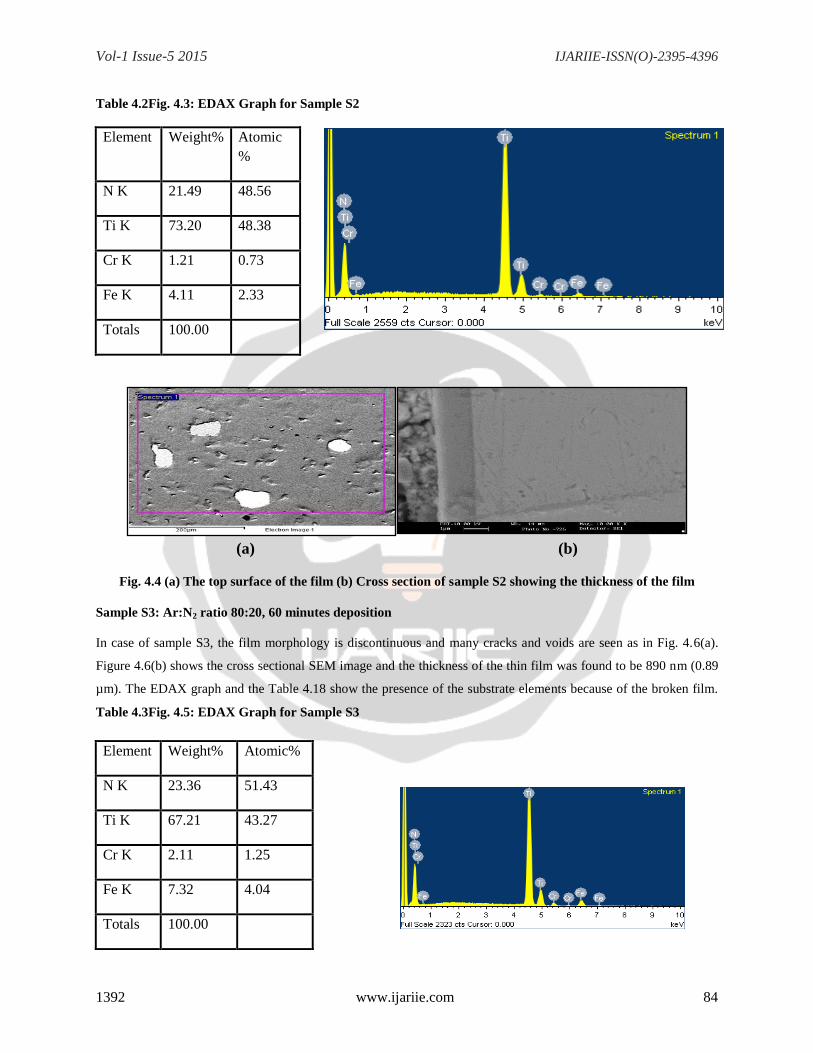
Sample S2: Ar:N2 ratio 90:10 without Ar plasma sputter cleaning and 60 minutes deposition
Here, as shown in Fig. 4.4(a), the film was discontinuous and features like depressions and protuberances are seen.
Furthermore, the substrate surface also shows voids. Figure 4.4(b) shows the cross-sectional SEM image and the
thickness of the film was found to be 1.5 µm.
Element Weight% Atomic
%
N K 21.65 48.58
Ti K 78.35 51.42
Totals 100.00
Vol-1 Issue-5 2015 IJARIIE-ISSN(O)-2395-4396
1392 www.ijariie.com 84
Table 4.2Fig. 4.3: EDAX Graph for Sample S2
Element Weight% Atomic
%
N K 21.49 48.56
Ti K 73.20 48.38
Cr K 1.21 0.73
Fe K 4.11 2.33
Totals 100.00
(a) (b)
Fig. 4.4 (a) The top surface of the film (b) Cross section of sample S2 showing the thickness of the film
Sample S3: Ar:N2 ratio 80:20, 60 minutes deposition
In case of sample S3, the film morphology is discontinuous and many cracks and voids are seen as in Fig. 4.6(a).
Figure 4.6(b) shows the cross sectional SEM image and the thickness of the thin film was found to be 890 nm (0.89
µm). The EDAX graph and the Table 4.18 show the presence of the substrate elements because of the broken film.
Table 4.3Fig. 4.5: EDAX Graph for Sample S3
Element Weight% Atomic%
N K 23.36 51.43
Ti K 67.21 43.27
Cr K 2.11 1.25
Fe K 7.32 4.04
Totals 100.00
Vol-1 Issue-5 2015 IJARIIE-ISSN(O)-2395-4396
1392 www.ijariie.com 85
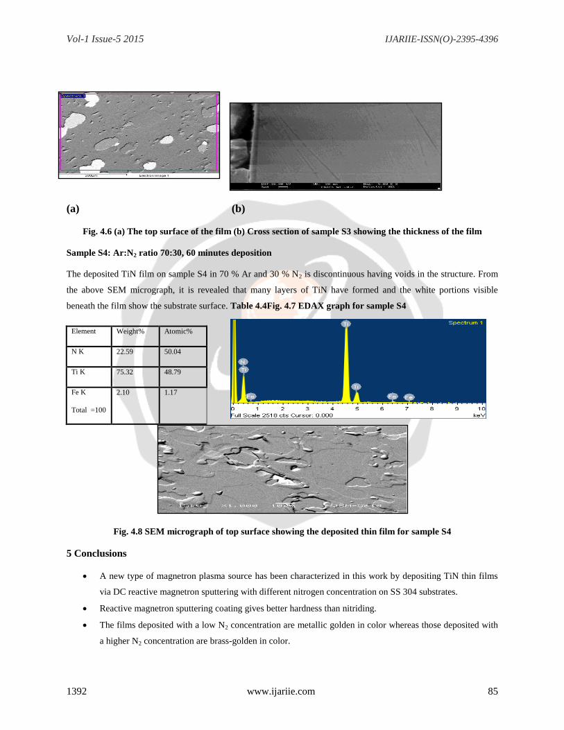
(a) (b)
Fig. 4.6 (a) The top surface of the film (b) Cross section of sample S3 showing the thickness of the film
Sample S4: Ar:N2 ratio 70:30, 60 minutes deposition
The deposited TiN film on sample S4 in 70 % Ar and 30 % N2 is discontinuous having voids in the structure. From
the above SEM micrograph, it is revealed that many layers of TiN have formed and the white portions visible
beneath the film show the substrate surface. Table 4.4Fig. 4.7 EDAX graph for sample S4
Element Weight% Atomic%
N K 22.59 50.04
Ti K 75.32 48.79
Fe K
Total =100
2.10 1.17
Fig. 4.8 SEM micrograph of top surface showing the deposited thin film for sample S4
5 Conclusions
A new type of magnetron plasma source has been characterized in this work by depositing TiN thin films
via DC reactive magnetron sputtering with different nitrogen concentration on SS 304 substrates.
Reactive magnetron sputtering coating gives better hardness than nitriding.
The films deposited with a low N2 concentration are metallic golden in color whereas those deposited with
a higher N2 concentration are brass-golden in color.
Vol-1 Issue-5 2015 IJARIIE-ISSN(O)-2395-4396
1392 www.ijariie.com 86
The gas ratio 60% Ar and 40% N2 resulted into a higher deposition rate of 1.45µm/hour and the average
microhardness was also observed to be around 3000 HV. Also the XRD results reveal the presence of
stoichiometric TiN.
The EDAX results indicate that at lower N2 concentration, the atomic % of Ti and N are almost nearly 50%
each, in agreement with the formation of stoichiometric TiN phase. However, at higher N2 concentration,
the nitrogen atomic % increases implying that the formation of other non-stoichiometric TiNx phases may
be possible which cannot be distinguished by XRD.
REFERENCES
[1]VipinChawla, R. Jayaganthan, Ramesh Chandra, Materials Characterization, 59 (2008) 1015-1020
[2] M.Y. Al-Jaroudi, H.T.G. Hentzell, S. Gong, Thin Solid Films 195 (1991) 63-76
[3]WitthawatWongpisan, KaninRuthairung, AutcharapornSrion, SuphakanKijamnajsuk, Panadda Sheppard,
Chiang Mai J. Sci. 2013; 40(5) : 857-864
[4]Y.L. Jeyachandran, Sa. K. Narayandass, D. Mangalaraj, Sami Areva, J.A.Mielczarski, Materials Scienceand
Engineering A 445-446 (2007) 223-226
[5] A. J. Aronson, D. Chen, W. H. Class, Thin Solid Films, 72(1980) 535-540
[6] Reza Bavadi, ShahooValedbagi, Materials Physics and Mechanics 15 (2012) 167- 172


![“CFD ANALYSIS HELICAL COIL HEAT EXCHANGER”ijariie.com/AdminUploadPdf/CFD_ANALYSIS_HELICAL_COIL_HEAT_E… · Shinde Digvijay D. et al. [3] studied the experimental investigation](https://img.pdfslide.net/doc/110x75/5fa1c8c0022f2e4c0b162c6a/aoecfd-analysis-helical-coil-heat-exchangera-shinde-digvijay-d-et-al-3-studied.jpg)