Embed Size (px)
Citation preview
CHARACTERIZATION OF FRECKLES IN A HIGH STRENGTH WROUGHT NICKEL SUPERALLOY
Paul D. Genereux and Christopher A. Borg
Pratt & Whitney United Technologies
400 Main Street East Hartford, Connecticut 06108
Abstract
Nickel base superalloys, such as Gatorizable Waspaloy@, U-720@, and Rene 88@ contain relatively high weight percents of hardening elements (e.g. Al & Ti), for a conventionally cast (VlM/VAR or VIM/ESR/VAR) and wrought (press and or rotary forged) product. Due to the higher volume fraction of gamma prime, this class of alloys has increased susceptibility for the formation of melt segregation defects, such as freckles. The propensity for freckle formation is further aggravated by the need for larger diameter ingots to support the trend toward higher thrust large diameter fan engines used on wide body twin engine aircraft. A review and assessment of production quality control techniques for freckle inspection are discussed. An in depth microstructural, chemical, and structural characterization is presented. The effects of freckle defects on key mechanical properties for the design of critical rotating engine components are shown. Finally, a brief discussion of a root cause investigation on the origin of freckle formation in this alloy class is given.
Gatorizable Waspaloy@ is a trademark of United Technologies Corporation U-720@ is a trademark of Special Metals Company Rene 88@ is a trademark of the General Electric Corporation
Introduction
Vacuum arc remelting (VAR) is the most commonly used process for the remelting of superalloys. The VAR process involves the continuous melting of a consumable electrode, typically cast in a vacuum induction melting (VIM) furnace or the product of an electroslag remelt (ESR) process. Melting is achieved by the striking of a DC arc under vacuum between the electrode and the melt pool. The melt pool solidifies in a water-cooled copper crucible. VAR turnace design has remained largely unchanged since its inception in the late 1950s. The significant advances came from furnace controls and in the area of automation of the melting and process control through the selection of optimum melting parameters. The primary benefits to the vacuum arc remelting process are: elimination of pipe, the removal of dissolved gases, the reduction of oxide inclusions, minimization of detrimental trace elements due to their high vapor pressure, and chemical uniformity.
Due to the physics of the process, consumable electrode melting also is associated with unique melt related defects in the form of solute segregation such as tree ring patterns, white spots and
19
freckles.’ Segregation resulting in tree rings is not considered to have a significant effect on mechanical properties; however, the latter two are generally considered to be detrimental. White spots, as the name suggests, appear as light etching regions and are generally lower in alloying elements (e.g., Ti or Nb). The formation of white spots is generally considered to be caused by one of the following three elements: 1.) fall-in of shelf or crown material into the melt pool, 2.) fall-in of unmelted dendrites from the consumable electrode, and 3.) localized decrease or arrest in the solidification rate. White spots are considered to be an unavoidable consequence of VAR processing.’ The primary goal for the melt source in controlling white spots is to minimize the occurrence and severity.
Freckles are characteristic of a deep melt pool causing interdendritic channeling of low-density element (e.g., Al and Ti) rich liquid. Other factors that may lead to tieckle formation are disruptions in electromagnetic fields and variation in heat transfer rates in the melt pool and mushy zone. Freckles are generally continuous and longitudinal in orientation and show up as dark etched spots in a macro-etched condition.3 They are most commonly, but not exclusively, found at an approximate mid- radial location in the ingot. Freckles consist of high concentrations of hardener elements (i.e. Ti or Nb) similar in chemistry to gamma prime (r’). Detection of freckles in both ingot and partially or fully converted billet form can be very difficult due to poor etch contrast, density similarities to the base metal, and the tendency not to crack even after significant ingot reduction.
Significant work has been conducted to gain a better understanding of freckle formation during the VAR process.4Z5 This work has focused on the elimination of freckles in the ingot through the use of tight process controls. The primary concerns with freckle containing material are the microstructural and chemical variations, which may result in the formation and concentration of phases significantly harder than the base metal. This high concentration of hardening elements has the potential to be detrimental to mechanical properties because of the presence of local hard and possibly brittle regions that may act as crack initiation sites. Limited literature is available which quantifies these chemical composition and hardness differences and especially the property debit associated with freckle defects. Specifically, very little literature exists regarding this type of melt
SoperaIloys 2ooo Edited byT.M. Pollock, R.D. Kissinger, R.R. Bowman,
K.A. Green, M. McLean, S. Olson, and J.J. Schirra TMS (The Minerals, Metals &Materials Society), 2ooO
defect in the class of wrought, high volume fraction y’ subsequently sectioned and the detailed metallurgical evaluation superalloys, which defines Gatorizahle Waspaloy. commenced.
Industry trends over the past several decades have pushed the envelope for achieving higher strength wrought alloys at larger ingot diameters. These trends have been largely fueled by the inherent cost and cleanliness benefits that modem wrought alloys have over powder metal product and by improvements in conventional melting and conversion techniques.
Wrought nickel based superalloys, specifically those containing relatively high percentages (> 35% by volume of y’) of hardening elements (e.g., Al and Ti), tend to be more susceptible to freckle formation due to the relatively narrow melt window for this alloy classification (e.g. Gatorizable Waspaloy, U-720, Rene 88, etc.). The inherent difficulty of freckle detection and the use of this product for critical rotating applications warrant an in-depth microstructural investigation and quantification of the effects of freckles on mechanical properties.
Background
In the early days of Gatorizable Waspaloy development, alloy melt difftculties were occasionally encountered in maintaining proper melt parameters resulting in the occurrence of freckles. This problem was further aggravated by the need for larger diameter ingots due to increased part size resulting from the trends towards larger fan diameter engines, and by the relatively high hardener element content for this material, as shown in Table I. Engines requiring this material, including the largest PW4000 models, have been developed to power a new generation of more fuel efftcient wide body commercial twin engine aircraft.
Table I Nominal Composition of Conventional Waspaloy & Gatorizable Waspaloy
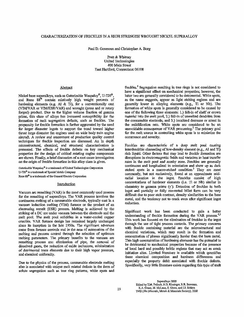
Figure 1: Photomicrograph of low density freckle found in Gatorizable Waspaloy LPT development shaft.
The freckle appeared darker than the matrix in a macroetched condition and microstructurally was found to contain a high volume fraction of large blocky ribbon-like and spheroidal precipitates that resembled overaged y’. This was all contained in a matrix of what appeared to be fine y’ in a gamma (7) matrix.
During the production process macro-etched plates are the primary means of screening melt segregation defects at the billet stage. This is necessary because down stream etch and visual inspection can be compromised by material flow and the complexity of the square cut ultrasonic and finished machined shapes.
Element
Ni Cr co C Ti Al
MO
B Zr
Conventional Gatorizable Waspaloy Waspaloy
Bal. Bal. 19.5 15.0 13.5 13.5 0.05 0.03 3.0 4.6 1.4 2.2 4.1 4.1
0.007 0.007 0.08 0.08
During the process development program, a point indication (Figure 1) was discovered during final macro-etch inspection of a Gatorizable Waspaloy low pressure turbine (LPT) shaft. Replica metallography showed a structure, of what appeared to be, a high density of y’ and large blocky ribbon-like precipitates of an unknown origin. This was believed to be a freckle melt segregation defect. This freckle indication had a diameter of 1.5 - 2.0 mm and was traced back to the I8 cm diameter billet running longitudinally equivalent to, or greater than 188 cm of billet length. This indication was located at a radial position of approximately 6 cm from the center line. The shaft was
Conventional nondestructive inspection techniques may need some optimization for the fail-safe detection of freckles in billet material. Work was initiated to investigate alternate and potentially more reliable etching procedures to highlight structural differences on a macro scale. Standard production macro-etchants applied to billet slices and square cut ultrasonic parts, can at times, show poor contrast for detecting the segregation associated with freckles, making reliable detection heavily dependant on inspector interpretation and diligence.
Ultrasonic inspectability of alloys in this classification, with fine uniform grain size (typically ASTM II), is generally very good due to the relatively low background noise. This fact, combined with the perceived hard and brittle nature of freckles due to local segregation and the significant reduction during conversion from ingot to billet, might be expected to result in cracking of the freckle defect, rendering it ultrasonically detectable. However, ultrasonic inspection of the part containing the freckle showed no evidence of any discontinuity despite conclusive evidence that the part contained a freckle defect.
A plan was formulated to conduct a thorough characterization of the defect. This plan involved fit11 metallurgical evaluation including detailed metallography, macro and microhardness, macro-etch development trials and a controlled quantitative ultrasonic evaluation. Additionally, chemistry and structural information was obtained through the use of x-ray diffraction and
20
electron microscopy employing energy and wavelength dispersive spectroscopy as well as selected area electron diffraction.
Analysis and Results
Based on the location and orientation of the defect in the billet and what appeared to be an increase in hardener elements, from a cursory chemical evaluation, the defect was most likely a freckle that formed due to melt segregation. The large blocky ribbon-like precipitates, contained within the freckle, were suspected to be eta (q). According to literature q phase (NisTi) exists in nickel based superalloys, particularly in alloys having high titanium/aluminum ratios, and it typically precipitates in a Widmanstatten appearing pattern. In contrast to face centered cubic (FCC) y and y’, n is hexagonal and forms to near stoichiometric composition with little or no solubility for other elements. Eta (q) does not precipitate as ra idly as y’ but grows more rapidly into coarse large precipitates. r Plans were made to evaluate this phase for hardness, chemical, and structural character.
(a> (b)
Most of the freckle evaluation conducted in this paper was done using freckles from the hot top region of a VAR ingot that experienced an identifiable melt disruption. These freckle defects showed a more well defined higher density of the suspected q phase and were more suited for the planned analyses. Although the suspected n phase within the freckle appeared denser than the indication found in the LPT shaft they appear visually identical in morphology.
Micro Metallography
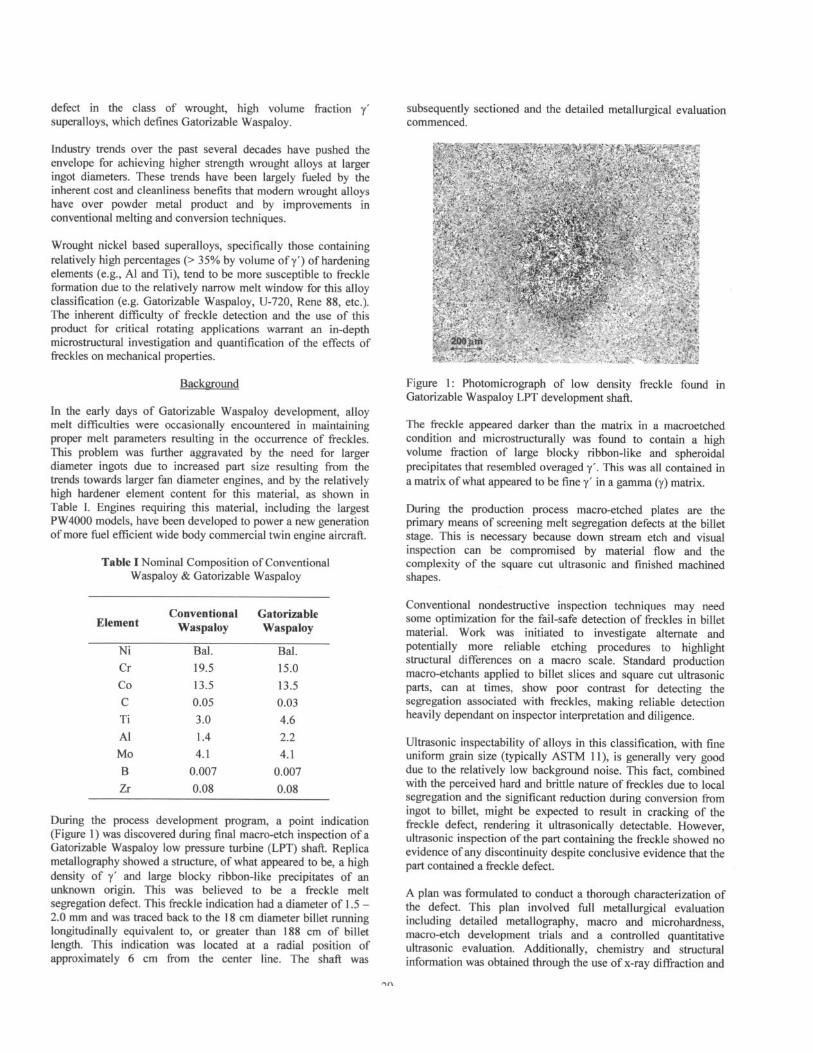
Optical micro metallography was performed in both a transverse and longitudinal orientation to the axis of the VAR ingot. In the as polished condition, an increase in MC carbides in the location of the freckle was observed, as compared to the base metal matrix location. Figures 2 & 3 are photomicrographs of the freckle in the transverse and longitudinal orientation. Common y’ etchants clearly define all features within the freckle. The suspect n phase appears particularly Widmanstatten in the longitudinal etched condition.
Figure 2: Photomicrographs of transverse section of freckle (a & b) from Gatorizable Waspaloy billet.
_-I- , . *:, *. _,’ * ,_. 9 .__.
.XS
.‘... ‘I.- - _ ,., .,.‘. -. l .
: _:. - . . -
. . . :.. .I . .--. .- .
_. _ -. . - . .
; _.
1
. . .-
zmpm . -
’ I_ ---
. .
(4
Figure 3: Photomicrographs of longitudinal section (a) as polished and (b & c) etched of freckle fiorn Gatorizable Waspaloy billet. Arrow in (b) denotes freckle width.
21
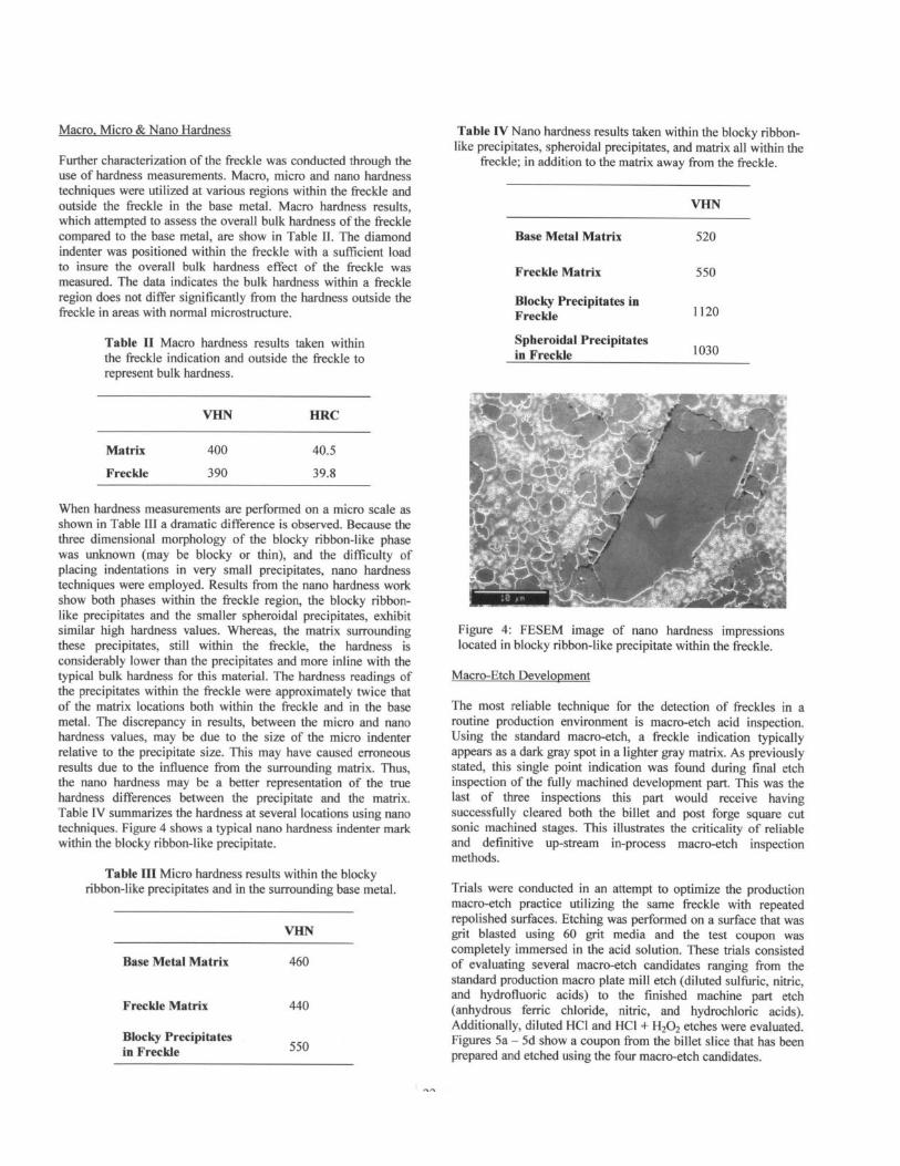
Macro, Micro & Nano Hardness
Further characterization of the freckle was conducted through the use of hardness measurements. Macro, micro and nano hardness techniques were utilized at various regions within the freckle and outside the freckle in the base metal. Macro hardness results, which attempted to assess the overall bulk hardness of the freckle compared to the base metal, are show in Table II. The diamond indenter was positioned within the freckle with a sufficient load to insure the overall bulk hardness effect of the freckle was measured. The data indicates the bulk hardness within a freckle region does not differ significantly from the hardness outside the freckle in areas with normal microstructure.
Table II Macro hardness results taken within the freckle indication and outside the freckle to represent bulk hardness.
VI-IN HRC
Matrix 400 40.5
Freckle 390 39.8
When hardness measurements are performed on a micro scale as shown in Table III a dramatic difference is observed. Because the three dimensional morphology of the blocky ribbon-like phase was unknown (may be blocky or thin), and the difficulty of placing indentations in very small precipitates, nano hardness techniques were employed. Results from the nano hardness work show both phases within the freckle region, the blocky ribbon- like precipitates and the smaller spheroidal precipitates, exhibit similar high hardness values. Whereas, the matrix surrounding these precipitates, still within the freckle, the hardness is considerably lower than the precipitates and more inline with the typical bulk hardness for this material. The hardness readings of the precipitates within the freckle were approximately twice that of the matrix locations both within the freckle and in the base metal. The discrepancy in results, between the micro and nano hardness values, may be due to the size of the micro indenter relative to the precipitate size. This may have caused erroneous results due to the influence from the surrounding matrix. Thus, the nano hardness may be a better representation of the true hardness differences between the precipitate and the matrix. Table IV summarizes the hardness at several locations using nano techniques. Figure 4 shows a typical nano hardness indenter mark within the blocky ribbon-like precipitate.
Table III Micro hardness results within the blocky ribbon-like precipitates and in the surrounding base metal.
Base Metal Matrix
Freckle Matrix
Blocky Precipitates in Freckle
460
440
550
Table IV Nano hardness results taken within the blocky ribbon- like precipitates, spheroidal precipitates, and matrix all within the
freckle; in addition to the matrix away from the freckle.
Base Metal Matrix 520
Freckle Matrix 550
Blocky Precipitates in Freckle
Spheroidal Precipitates in Freckle
1120
1030
.i .,.
Figure 4: FESEM image of nano hardness impressions located in blocky ribbon-like precipitate within the freckle.
Macro-Etch Development
The most reliable technique for the detection of freckles in a routine production environment is macro-etch acid inspection. Using the standard macro-etch, a freckle indication typically appears as a dark gray spot in a lighter gray matrix. As previously stated, this single point indication was found during final etch inspection of the fully machined development part. This was the last of three inspections this part would receive having successfully cleared both the billet and post forge square cut sonic machined stages. This illustrates the criticality of reliable and definitive up-stream in-process macro-etch inspection methods.
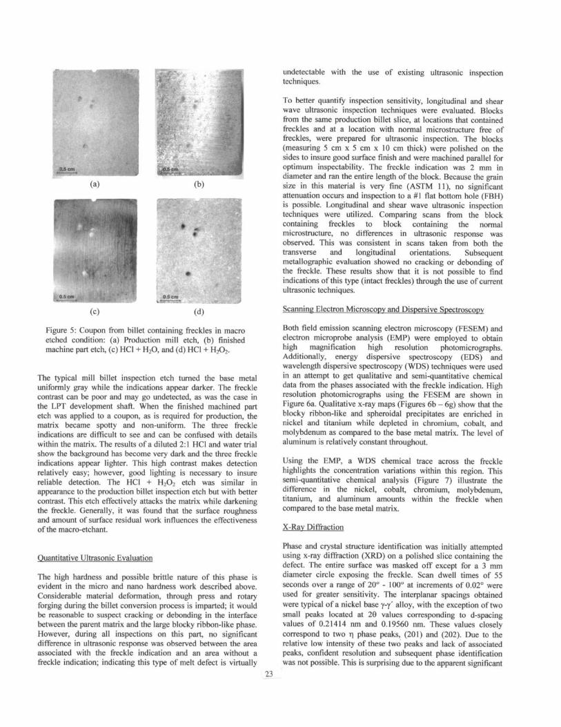
Trials were conducted in an attempt to optimize the production macro-etch practice utilizing the same freckle with repeated repolished surfaces. Etching was performed on a surface that was grit blasted using 60 grit media and the test coupon was completely immersed in the acid solution. These trials consisted of evaluating several macro-etch candidates ranging from the standard production macro plate mill etch (diluted sulfuric, nitric, and hydrofluoric acids) to the finished machine part etch (anhydrous ferric chloride, nitric, and hydrochloric acids). Additionally, diluted HCI and HCI + Hz02 etches were evaluated. Figures Sa - 5d show a coupon from the billet slice that has been prepared and etched using the four macro-etch candidates.
cc>
0.5 cm *--.-_
(b)
* f
0.5 cm ,--
(4
Figure 5: Coupon from billet containing freckles in macro etched condition: (a) Production mill etch, (b) finished machine part etch, (c) HCI + H20, and (d) HCI + H202.
The typical mill billet inspection etch turned the base metal uniformly gray while the indications appear darker. The freckle contrast can be poor and may go undetected, as was the case in the LPT development shaft. When the finished machined part etch was applied to a coupon, as is required for production, the matrix became spotty and non-uniform. The three freckle indications are difficult to see and can be confused with details within the matrix. The results of a diluted 2:l HCI and water trial show the background has become very dark and the three freckle indications appear lighter. This high contrast makes detection relatively easy; however, good lighting is necessary to insure reliable detection. The HCI + Hz02 etch was similar in appearance to the production billet inspection etch but with better contrast. This etch effectively attacks the matrix while darkening the freckle. Generally, it was found that the surface roughness and amount of surface residual work influences the effectiveness of the macro-etchant.
Ouantitative Ultrasonic Evaluation
The high hardness and possible brittle nature of this phase is evident in the micro and nano hardness work described above. Considerable material deformation, through press and rotary forging during the billet conversion process is imparted; it would be reasonable to suspect cracking or debonding in the interface between the parent matrix and the large blocky ribbon-like phase. However, during all inspections on this part, no significant difference in ultrasonic response was observed between the area associated with the freckle indication and an area without a freckle indication; indicating this type of melt defect is virtually
23
undetectable with the use of existing ultrasonic inspection techniques.
To better quantify inspection sensitivity, longitudinal and shear wave ultrasonic inspection techniques were evaluated. Blocks from the same production billet slice, at locations that contained freckles and at a location with normal microstructure free of freckles, were prepared for ultrasonic inspection. The blocks (measuring 5 cm x 5 cm x 10 cm thick) were polished on the sides to insure good surface finish and were machined parallel for optimum inspectability. The freckle indication was 2 mm in diameter and ran the entire length of the block. Because the grain size in this material is very fine (ASTM ll), no significant attenuation occurs and inspection to a #l flat bottom hole (FBH) is possible. Longitudinal and shear wave ultrasonic inspection techniques were utilized. Comparing scans from the block containing freckles to block containing the normal microstructure, no differences in ultrasonic response was observed. This was consistent in scans taken from both the transverse and longitudinal orientations. Subsequent metallographic evaluation showed no cracking or debonding of the freckle. These results show that it is not possible to find indications of this type (intact freckles) through the use of current ultrasonic techniques.
Scanning Electron Microscopy and Dispersive Spectroscopy
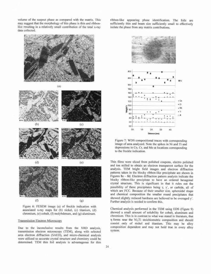
Both field emission scanning electron microscopy (FESEM) and electron microprobe analysis (EMP) were employed to obtain high magnification high resolution photomicrographs. Additionally, energy dispersive spectroscopy (EDS) and wavelength dispersive spectroscopy (WDS) techniques were used in an attempt to get qualitative and semi-quantitative chemical data from the phases associated with the freckle indication. High resolution photomicrographs using the FESEM are shown in Figure 6a. Qualitative x-ray maps (Figures 6b - 6g) show that the blocky ribbon-like and spheroidal precipitates are enriched in nickel and titanium while depleted in chromium, cobalt, and molybdenum as compared to the base metal matrix. The level of aluminum is relatively constant throughout.
-
Using the EMP, a WDS chemical trace across the freckle highlights the concentration variations within this region. This semi-quantitative chemical analysis (Figure 7) illustrate the difference in the nickel, cobalt, chromium, molybdenum, titanium, and aluminum amounts within the freckle when compared to the base metal matrix.
X-Ray Diffraction
Phase and crystal structure identification was initially attempted using x-ray diffraction (XRD) on a polished slice containing the defect. The entire surface was masked off except for a 3 mm diameter circle exposing the freckle. Scan dwell times of 55 seconds over a range of 20’ - 100” at increments of 0.02” were used for greater sensitivity. The interplanar spacings obtained were typical of a nickel base y-y’ alloy, with the exception of two small peaks located at 20 values corresponding to d-spacing values of 0.21414 nm and 0.19560 nm. These values closely correspond to two 1 phase peaks, (201) and (202). Due to the relative low intensity of these two peaks and lack of associated peaks, confident resolution and subsequent phase identification was not possible. This is surprising due to the apparent significant
volume of the suspect phase as compared with the matrix. This may suggest that the morphology of this phase is thin and ribbon- 11!:e resulting in a relatively small contribution of the total x-ray data collected.
(4
(9
(e)
Figure 6: FESEM image (a) of freckle indication with associated x-ray maps for (b) nickel, (c) titanium, (d) chromium, (e) cobalt, (f) molybdenum, and (g) aluminum.
Transmission Electron Microscony
Due to the inconclusive results from the XRD analysis, transmission electron microscopy (TEM), along with selected area electron diffraction (SAED), and micro-chemical analysis were utilized so accurate crystal structure and chemistry could be determined. TEM thin foil analysis is advantageous for thin
ribbon-like appearing phase identification. The foils are sufftciently thin and beam size sufficiently small to effectively isolate the phase from any matrix contributions.
a5 1.5 25 35 45
Figure 7: WDS compositional traces with corresponding image of area analyzed. Note the spikes in Ni and Ti and depressions in Co, Cr, and MO at locations corresponding to the freckle indication.
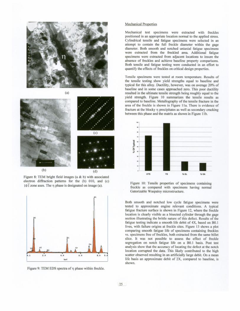
Thin films were sliced from polished coupons, electro polished and ion milled to obtain an electron transparent surface for the analysis. TEM bright field images and electron diffraction patterns taken in the blocky ribbon-like precipitate are shown in Figures 8a - 8d. Electron diffraction pattern analysis indicate the blocky ribbon-like precipitate to have an ordered hexagonal crystal structure. This is significant in that it rules out the possibility of these precipitates being 7, y’, or carbide, all of which are FCC. Because of their smaller size, spheroidal shape and chemical composition the smaller round precipitates that showed slightly reduced hardness are believed to be overaged y’. Further analysis is needed to confirm this.
Chemical analysis performed in the TEM using EDS (Figure 9) showed a small amount of solubility for cobalt, aluminum and chromium. This is in contrast to what was stated in literature, that q forms near the NisTi stoichiometric composition and should consist only of nickel and titanium. This may be alloy composition dependent and may not hold true in every alloy system.
24
(a)
(4 Figure 8: TEM bright field images (a & b) with associated electron diffraction patterns for the (b) 010, and (c) lOTzone axes. The n phase is designated on image (a).
Mechanical Properties
Mechanical test specimens were extracted with freckles positioned in an appropriate location normal to the applied stress. Cylindrical tensile and fatigue specimens were selected in an attempt to contain the full freckle diameter within the gage diameter. Both smooth and notched uniaxial fatigue specimens were extracted from the freckled area. Additional fatigue specimens were extracted from adjacent locations to insure the absence of freckles and achieve baseline property comparisons. Both tensile and fatigue testing were conducted in an effort to quantify the effects of freckles on critical design properties.
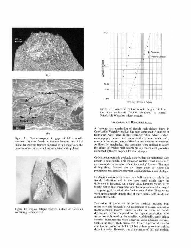
Tensile specimens were tested at room temperature. Results of the tensile testing show yield strengths equal to baseline and typical for this alloy. Ductility, however. was on average 20% of baseline and in some cases approached zero. This poor ductility resulted in the ultimate tensile strength being roughly equal to the yield strength. Figure IO summarizes the tensile results as compared to baseline. Metallography of the tensile fracture in the area of the freckle is shown in Figure 1 la. There is evidence of fracture at the blocky n precipitates as well as secondary cracking between this phase and the matrix as shown in Figure 11 b.
Figure IO: Tensile properties of specimens containing freckle as compared with specimens having normal Gatorizable Waspaloy microstructure.
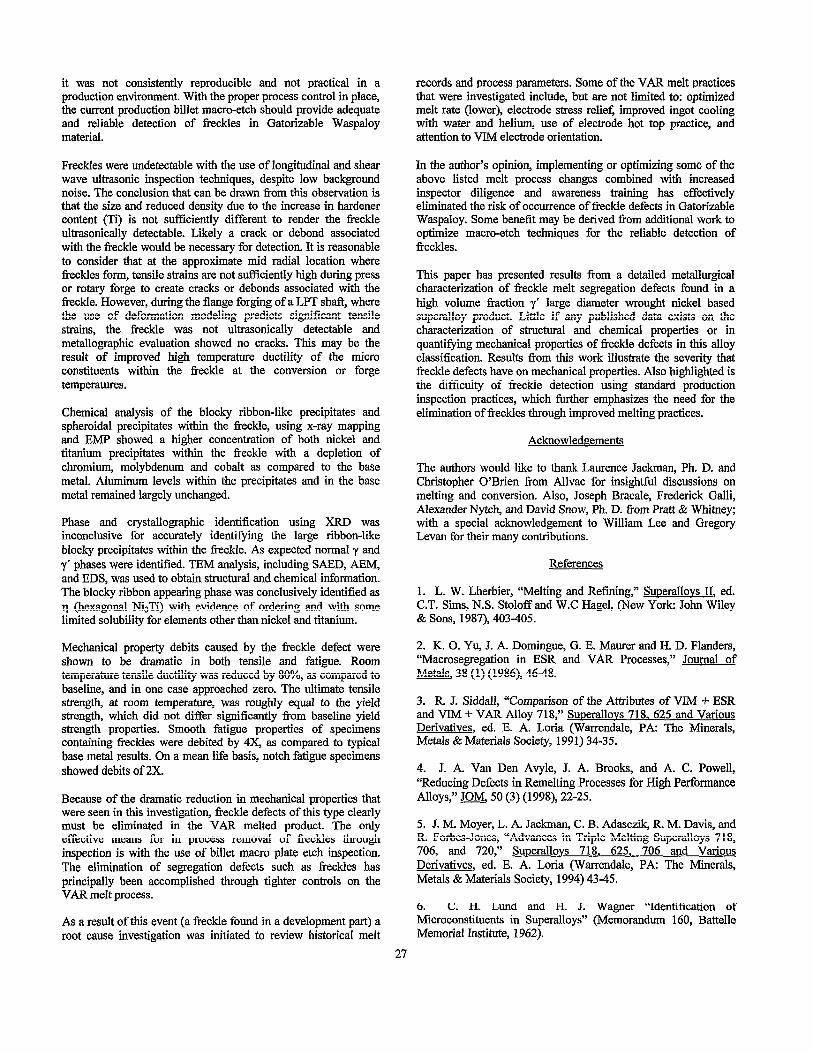
Both smooth and notched low cycle fatigue specimens were tested to approximate engine relevant conditions. A typical fatigue fracture surface is shown in Figure 12, where the freckle location is clearly visible as a bisected cylinder through the gage section illustrating the brittle nature of this defect. Results of the fatigue testing indicate a smooth life debit of 4X, based on B0.1 lives, with failure origins at freckle sites. Figure 13 shows a plot comparing smooth fatigue life of specimens containing freckles vs. specimens free of freckles, both extracted from the same billet slice. It was not possible to assess the effect of freckle segregation on notch fatigue life on a B0.l basis. Post test analysis show that the accuracy of locating the defect at the notch location corrupted the data. This likely contributed to the high scatter observed resulting in an artificially large debit. On a mean life basis an approximate debit of 2X, compared to baseline, is shown.
Figure 9: TEM EDS spectra of n phase within freckle.
5.0
F 1 .oo+
erial
Nonalized Cycles to Failure
Figure 13: Lognormal plot of smooth fatigue life from specimens containing freckles compared to normal Gatorizable Waspaloy microstructure.
Conclusions and Recommendations
A thorough characterization of freckle melt defects found in Gatorizable Waspaloy product has been completed. A number of techniques were used in this characterization which include metallography, macro and nano hardness, macro-etch trails, ultrasonic inspection, x-ray diffraction and electron microscopy. Additionally, mechanical test specimens were utilized to assess the effects of freckle melt defects on key mechanical properties associated with aero engine LPT shaft designs.
@I Figure 11: Photomicrograph in gage of failed tensile specimen (a) note freckle at fracture location, and SEM image (b) showing fracture occurred on n platelets and the presence of secondary cracking associated with n phase.
Optical metallographic evaluation shows that the melt defect does appear to be a freckle. This indication contains what seems to be an increased concentration of carbides and y’ formers. The most distinguishing features are the large plate or ribbon-like precipitates that appear somewhat Widmanstatten in morphology.
Hardness measurements taken on a bulk or macro scale in the freckle indication and in the base metal matrix show no difference in hardness. On a nano scale, hardness values in the blocky ribbon-like precipitates and the large spheroidal overaged y’ appearing phase within the freckle were similar. These values were approximately double that of the y matrix both inside and outside the freckle.
Figure 12: Typical fatigue fracture surface of specimen containing freckle defect.
Evaluation of production inspection methods included both macro-etch and ultrasonic. An assessment of several alternative macro-etchants showed similar results, in terms of freckle delineation, when compared to the typical production billet inspection etch, used by the supplier. Additionally, some unique contrast enhancements were observed using alternate etchants, such as the HCl + Hz02 macro-etch. This etch produced a similar effect to the production billet etch but with more contrast making detection easier. However, due to the nature of this etch method,
26
it was not consistently reproducible and not practical in a records and process parameters. Some of the VAR melt practices production environment. With the proper process control in place, that were investigated include, but are not limited to: optimized the current production billet macro-etch should provide adequate melt rate (lower), electrode stress relief, improved ingot cooling and reliable detection of freckles in Gatorizable Waspaloy with water and helium, use of electrode hot top practice, and material. attention to VIM electrode orientation.
Freckles were undetectable with the use of longitudinal and shear wave ultrasonic inspection techniques, despite low background noise. The conclusion that can be drawn Tom this observation is that the size and reduced density due to the increase in hardener content (Ti) is not sufficiently different to render the f?eckle ultrasonically detectable. Likely a crack or debond associated with the freckle would be necessary for detection. It is reasonable to consider that at the approximate mid radial location where freckles form, tensile strains are not sufficiently high during press or rotary forge to create cracks or debonds associated with the freckle. However, during the flange forging of a LPT shaft, where the use of deformation modeling predicts significant tensile strains, the freckle was not ultrasonically detectable and metallographic evaluation showed no cracks. This may be the result of improved high temperature ductility of the micro constituents within the freckle at the conversion or forge temperatures.
Chemical analysis of the blocky ribbon-like precipitates and spheroidal precipitates within the freckle, using x-ray mapping and EMP showed a higher concentration of both nickel and titanium precipitates within the freckle with a depletion of chromium, molybdenum and cobalt as compared to the base metal. Aluminum levels within the precipitates and in the base metal remained largely unchanged.
Phase and crystallographic identification using XRD was inconclusive for accurately identifying the large ribbon-like blocky precipitates within the iieckle. As expected normal y and y’ phases were identified. TEM analysis, including SAED, AEM, and EDS, was used to obtain structural and chemical information. The blocky ribbon appearing phase was conclusively identified as 11 (hexagonal NisTi) with evidence of ordering and with some limited solubility for elements other than nickel and titanium.
Mechanical property debits caused by the freckle defect were shown to be dramatic in both tensile and fatigue. Room temperature tensile ductility was reduced by SO%, as compared to baseline, and in one case approached zero. The ultimate tensile strength, at room temperature, was roughly equal to the yield strength, which did not differ significantly from baseline yield strength properties. Smooth fatigue properties of specimens containing freckles were debited by 4X, as compared to typical base metal results. On a mean life basis, notch fatigue specimens showed debits of 2X.
Because of the dramatic reduction in mechanical properties that were seen in this investigation, freckle defects of this type clearly must be eliminated in the VAR melted product. The only effective means for in process removal of tiefreckles through inspection is with the use of billet macro plate etch inspection. The elimination of segregation defects such as freckles has principally been accomplished through tighter controls on the VAR melt process.
As a result of this event (a freckle found in a development part) a root cause investigation was initiated to review historical melt
In the author’s opinion, implementing or optimizing some of the above listed melt process changes combined with increased inspector diligence and awareness training has effectively eliminated the risk of occurrence of freckle defects in Gatorizable Waspaloy. Some benefit may be derived from additional work to optimize macro-etch techniques for the reliable detection of freckles.
This paper has presented results from a detailed metallurgical characterization of freckle melt segregation defects found in a high volume fiaction y’ large diameter wrought nickel based superalloy product. Little if any published data exists on the characterization of structural and chemical properties or in quantifying mechanical properties of freckle defects in this alloy classification. Results from this work illustrate the severity that freckle defects have on mechanical properties. Also highlighted is the difficulty of tieckle detection using standard production inspection practices, which further emphasizes the need for the elimination of freckles through improved melting practices.
Acknowledgements
The authors would like to thank Laurence Jackman, Ph. D. and Christopher O’Brien from Allvac for insightful discussions on melting and conversion. Also, Joseph Bracale, Frederick Galli, Alexander Nytch, and David Snow, Ph. D. from Pratt & Whitney; with a special acknowledgement to William Lee and Gregory Levan for their many contributions.
References
1. L. W. Lherbier, “Melting and Refining,” Suuerallovs II, ed. C.T. Sims, N.S. Stoloff and W.C Hagel, (New York: John Wiley & Sons, 1987), 403-405.
2. K. 0. Yu, J. A. Domingue, G. E. Maurer and H. D. Flanders, “Macrosegregation in ESR and VAR Processes,” Journal of Metals, 38 (1) (1986), 46-48.
3. R J. Siddall, “Comparison of the Attributes of VIM C ESR and VIM + VAR Alloy 718,” Suoerallovs 718, 625 and Various Derivatives, ed. E. A. Loria (Warrendale, PA: The Minerals, Metals & Materials Society, 1991) 34-35.
4. J. A. Van Den Avyle, J. A. Brooks, and A. C. Powell, “Reducing Defects in Remelting Processes for High Performance Alloys,” JOM. 50 (3) (1998), 22-25.
5. J. M. Moyer, L. A. Jackman, C. B. Adasczik, R. M. Davis, and R. Forbes-Jones, “Advances in Triple Melting Superalloys 718, 706, and 720,” Superalloys 718. 625, 706 and Various Derivatives, ed. E. A. Loria (Warrendale, PA: The Minerals, Metals & Materials Society, 1994) 43-45.
6. C. H. Lund and H. J. Wagner “Identification of I Microconstituents in Superalloys” (Memorandum 160, Battelle Memorial Institute, 1962).
21


![Advanced Cast Aluminum Alloys - DTIC · Wrought 7055 aluminum alloy is the highest strength conventionally processed, commercially available, wrought aluminum alloy [2]. The yield](https://img.pdfslide.net/doc/110x75/5f33c89d21254a014f5911cb/advanced-cast-aluminum-alloys-dtic-wrought-7055-aluminum-alloy-is-the-highest.jpg)