Embed Size (px)
Citation preview
Characterization of Multi-Antenna GNSS
Multi-Sensor Attitude Determination for Stratospheric
Balloon Platforms
Nathan Tehranilowast and Jason Grossdagger
West Virginia University Morgantown WV 26506 USA
In this paper a multi-antenna Global Navigation Satellite System (GNSS) multi-sensorattitude estimation algorithm is outlined and its sensitivity to various error sources isassessed The attitude estimation algorithm first estimates attitude using multiple GNSSantennas and then fuses a host of other attitude estimation sensors including tri-axialmagnetometers Sun sensors and inertial sensors This work is motivated by the attitudedetermination needs of the Antarctic Impulse Transient Antenna (ANITA) experiment ahigh-altitude balloon-lofted science platform In order to assess performance trade-offs ofvarious algorithm configurations the attitude estimation performance of various approachesis tested using a simulation that is based on recorded ANITA III flight data For GNSSerrors attention is focused on multipath receiver measurement noise and carrier-phasebreaks For the remaining attitude sensors different grades of sensor are assessed Througha Monte-Carlo simulation it is shown that under typical conditions sub-01 degree attitudeaccuracy is available when use multiple antenna GNSS data only but that this accuracycan degrade to degree-level in some environments warranting the inclusion of additionalattitude sensors to maintain the desired level of accuracy
I Introduction
This document outlines the development simulation and testing of an attitude determination algorithmIt is motivated by the requirements of the Antarctic Impulse Transient Antenna (ANITA) experimentANITA is an ongoing project that uses a balloon-lofted platform to detect radio impulses from high-energyparticle collisions in the ice below Ultra-high energy neutrinos (UHEN) and ultra-high energy cosmic rays(UHECR) have both been detected by IceCube a ground-based neutrino observatory which uses detectorsembedded in ice1 ANITA with its high operating altitude can observe possible particle collisions in asignificantly-larger volume of ice2
The ANITA I II and III flight platforms have made successful radio transient discoveries23 ANITAuses several feed-horn antennas with narrow observation beams and a high degree of pointing precision foreach antenna For any airborne sensing platform the pointing accuracy is dependent on the accuracy ofthe onboard attitude solution4 As such a key to high pointing accuracy is a robust attitude-determinationsystem
Attitude determination using multi-antenna GNSS observations is an established process first proposedby Cohen in 19915 It was also adapted for aircraft use6 and tested by the same author7 Multi-antennaGNSS attitude determination has been tested on ground waterborne and flight vehicles8 and the technologyhas matured to multiple commercially-available products910 There has been considerable effort to simulategyroscope-free attitude determination using 3-axis magnetometers 2-axis Sun sensors or both for spacecraftapplications11 Highlights include the use of a magnetometer-only Sun-pointing algorithm by Ahn 200312
This method did not include filtering and was used to estimate an attitude vector which was being correctedMagnetometer-derived attitude was within 3 of gyroscope-derived truth for the entire investigated flightPsiaki (1991) modeled an orbit- and attitude-determination algorithm13 Using a 10nT 3-axis magnetometer
lowastGraduate Research Assistant Department of Mechanical and Aerospace Engineering (MAE) Morgantown WV AIAAStudent MemberdaggerAssistant Professor Department of MAE Morgantown WV AIAA Senior Member
1 of 16
American Institute of Aeronautics and Astronautics
Dow
nloa
ded
by W
EST
VIR
GIN
IA U
NIV
ER
SIT
Y o
n Ja
nuar
y 10
201
7 | h
ttp
arc
aiaa
org
| D
OI
10
2514
62
017-
1554
AIAA Modeling and Simulation Technologies Conference
9 - 13 January 2017 Grapevine Texas
AIAA 2017-1554
Copyright copy 2017 by Nathan Tehrani Jason Gross Published by the American Institute of Aeronautics and Astronautics Inc with permission
AIAA SciTech Forum
and a 0005 Sun sensor this method showed less than 01 error in all axes Crassidis (1996) created a Sunsensor and magnetometer Kalman filter and showed that a magnetometer-only attitude estimate is markedlyimproved (error reduced by approximately half) with the inclusion of Sun sensor data11 The Balloon-borneLarge Aperture Submillimeter Telescope for Polarimetry (BLASTPol) is a similar stratospheric platformthat uses Kalman filtering of multi sensor data for post-flight attitude determination4
Multi-antenna GNSS has been used for remote sensing platforms since shortly after its proposal14 andit is in use on multiple stratospheric balloon platforms4 This paper outlines the design and performanceevaluation of a GNSS-based attitude estimator that is then augmented with various other attitude sensorsto offer a proposed algorithm for the ANITA project or other similar balloon-based payloads
This remainder of this paper is organized as follows In Section II the simulation environment and thesensor data simulation is discussed In Section III the design of the baseline estimation filter and attitudeestimation filter are discussed Section IV the performance of the GNSS-based and multi-sensor attitudeestimators are presented and discussed Section V summarizes this studyrsquos findings and discusses futurework
II Data Simulation
IIA Flight Profile
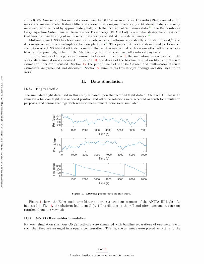
The simulated flight data used in this study is based upon the recorded flight data of ANITA III That is tosimulate a balloon flight the onboard position and attitude solutions were accepted as truth for simulationpurposes and sensor readings with realistic measurement noise were simulated
0 1000 2000 3000 4000 5000 6000 7000
Time (s)
-08-06-04-02
Roll
(deg)
0 1000 2000 3000 4000 5000 6000 7000
Time (s)
0
05
1
Pitch (
deg)
1000 2000 3000 4000 5000 6000 7000
Time (s)
0
100
200
300
Yaw
(deg)
Figure 1 Attitude profile used in this work
Figure 1 shows the Euler angle time histories during a two-hour segment of the ANITA III flight Asindicated in Fig 1 the platform had a small (lt 1) oscillation in the roll and pitch axes and a constantrotation about the yaw axis
IIB GNSS Observables Simulation
For each simulation run four GNSS receivers were simulated with baseline separations of one-meter eachsuch that they are arranged in a square configuration That is the antennas were placed according to the
2 of 16
American Institute of Aeronautics and Astronautics
Dow
nloa
ded
by W
EST
VIR
GIN
IA U
NIV
ER
SIT
Y o
n Ja
nuar
y 10
201
7 | h
ttp
arc
aiaa
org
| D
OI
10
2514
62
017-
1554
following matrix Rb
Rb =
x2b y2b z2b
x3b y3b z3b
x4b y4b z4b
(1)
where xib yib and zib are the body-centric coordinates of the ith antenna i = 1 denoting the masterantenna as was done by Cohen in the first paper describing multi-antenna attitude determination5 GNSScarrier-phase data was simulated for each flight profile at a rate of 10 Hz using the MATLAB SatNavToolbox15 which was modified by Watson et al (2016)16 to include additional GNSS error sources
A number of deterministic and non-deterministic error sources are associated with GNSS measurements17
Fortunately for attitude estimation applications several of the primary GNSS error sources includingsatellite and receiver clock biases and atmospheric delays are canceled through the use of double differencedGNSS observations17 However two important error sources namely multipath reflections and carrier-phasebreaks (AKA cycle-slips) remain present In particular when a metallic object reflects a GNSS signalonto the antenna the multiple paths induce errors17 This could be a large problem on balloon-basedscientific platforms as the antennas are spaced closely and in close proximity to science payload Thermalmeasurement noise in the receiver is another error source it is actually amplified by double differencingGNSS data As such for this simulation study multipath carrier-phase breaks and receiver thermal errorswere assessed with respect to their effect on the attitude estimatorrsquos performance using the distributionsindicated in Table 1
IIC Inertial Measurement Simulation
In addition to GNSS measurements inertial measurement unit data was simulated for each flight profileand data at a sampling rate of 200 Hz In particular four grades of IMU tri-axial rate gyroscope andaccelerometers were simulated assessed In this case ideal gyroscope readings were generated by acceptingthe truth attitude solution of the ANITA III flight These ideal measurements were then polluted with botha time-varying bias and a white noise component The magnitude of these two noise terms were selectedbased on the grade of the inertial sensors assumed which were varied as indicated in Table 1
IID Sun Sensor amp Magnetometer Simulation
Two-axis Sun-sensor data and tri-axial magnetometer data were also simulated for each flight based onthe measurement models and uncertainties of the sensors current installed on the ANITA IV balloon Inparticular the apparent Sun position and the Earthrsquos magnetic field along the flight profile were calculatedand sensor measurements were simulated by polluting these true values with random noise based on themeasurement noises quoted by the manufacturersrsquo spec sheets as indicated in Table 1
The magnetometer data consists of magnetic field intensity measurements (Bb) in three orthogonal di-rections corresponding to the North N East E and down D axes in the body frame b This begins withBE a vector constraining the simulated magnetic field intensities in the navigation frame generated at eachlocation along the flight path
~BE =
BbN
BbE
BbD
(2)
Body-frame magnetic field measurements are generated by multiplying truth attitude (represented bythe direction-cosine matrix Cbn) by the navigation-frame magnetic field
~Bb = Cbn ~BE (3)
With three contributing error sources added hard and soft iron errors and measurement noise in asimplified method as described by Gebre-Egziabher et al18
B = Asi ~Bb + ~Bhi (4)
3 of 16
American Institute of Aeronautics and Astronautics
Dow
nloa
ded
by W
EST
VIR
GIN
IA U
NIV
ER
SIT
Y o
n Ja
nuar
y 10
201
7 | h
ttp
arc
aiaa
org
| D
OI
10
2514
62
017-
1554
where Asi is a 3times 3 matrix which describes the soft-iron error effect and ~Bhi is a 3times 1 vector containingthe hard-iron offset a magnetic field generated by ferromagnetic material on the platform For this studynominal values for Asi and ~Bhi were used based on the calibrations in the Gebre-Egziabher paper Simulatedmeasurement noise was then added to B corresponding to precision level of the modeled magnetometer
The simulated Sun sensor data consists of solar incidence angles 6 X and 6 Y relative to to the twohorizontal body-frame axes Xb and Yb These were generated using the apparent solar azimuth θSun andelevation φSun calculated for each epoch of the flight duration First the solar azimuth and elevation valuesare transformed into a unit vector representing the Sunrsquos position in the sky with respect to the navigationframe n
VSunn =
Sunxn
Sunyn
Sunzn
(5)
This unit-vector is then transformed using the nav-to-body direction cosine marix Cbn
VSunb = CbnVSunn (6)
and the solar incidence angles 6 X and 6 Y are then calculated
6 X = π2 + atan2(SunzbSunxb) (7)
6 Y = π2 + atan2(SunzbSunyb) (8)
where atan2 is the four-quadrant tangent inverseAs with the magnetometer measurements simulated measurement noise was added to the Sun sensor
measurements However in the case of a Sun sensor as measurement noise increases at low solar eleva-tions the measurement noise was scaled according to solar elevation angle Sun sensor measurements weresimulated at 10Hz intervals
IIE Simulation Overview
For this study a total of 50 one-hour flight profiles were simulated in a Monte-Carlo manner In particularthe ECEF starting positions magnitude of GNSS error sources and quality of IMU Magnetometer and Sunsensor data were varied as indicate in Table 1 Note that by randomly varying the starting location theGNSS constellation satellite geometry was randomized as well
III Attitude Estimation
IIIA Algorithm Overview
Figure 2 shows the overall algorithm used First a carrier-phase differential GNSS filter as detailed inSection IIIB estimates the baselines between antennas Next this information is used as a measurementupdate for a GNSS-only multiple antenna attitude estimator as described in Section IIIC in which theattitude estimates are smoothed by assuming typical low-dynamic balloon flights Finally the resultingestimated attitude state is optionally fused with a multi-sensor estimator that also incorporates inertialmagnetometer and Sun sensor data as discussed in Section IIID
4 of 16
American Institute of Aeronautics and Astronautics
Dow
nloa
ded
by W
EST
VIR
GIN
IA U
NIV
ER
SIT
Y o
n Ja
nuar
y 10
201
7 | h
ttp
arc
aiaa
org
| D
OI
10
2514
62
017-
1554
Table 1 Sensor Error-Source Monte-Carlo Simulation Distribution Parameters
Error-Sources Model Parameters Notes
Thermal Noise σρ = 032m σφ = 016λ linear scale factor randomly se-lected between [01]
Multipath 10 intensity σ = 04m τ = 15sec linear scale factor randomly se-lected between [02]
Tropospheric Delay Percent of error assumed handled by broad-cast correction
Modified Hopfield with linearscale factor randomly selectedbetween [095105]
Ionospheric Delay First order ionospheric effects mitigated withdual-frequency
linear scale factor randomly se-lected between [071]
Carrier phase break Likelihood set to 1 phase break per 24 minuteto 1 phase break per 240 minutes
Gyroscope In-run Bias σ = 96eminus6 radsec ARW = 02 degradichr
Scaled Honeywell HG1700AG72SF = ( 1
50 1200 1
400 )
Sun Sensor Zenith measurement noise σ = 01 deg Scaled SolarMEMS ISSDX-60SF = (1 2 3 4)
Magnetometer Measurement noise σ = 267 nTAsi terms scaled between [0005 001]~Bhi terms scaled between [25nT 50nT]
Scaled ST LSM9DS0SF = (1 5 10)
Figure 2 Block diagram showing the three main estimators baseline-estimation filter GNSS-only attitude estimatorand multi-sensor attitude estimator
IIIB Antenna Baseline Estimation Filter
A Kalman filter is used to estimate the relative position between each of the antennas and a single masterantenna at each of the 10 Hz measurement epochs In particular this Kalman filter uses Carrier-phase Dif-ferential GNSS (CD-GNSS) measurements to estimate the relative position vectors between the antennas17
The state vector x for this filter consists of the relative position vector components between antennarsquos A
5 of 16
American Institute of Aeronautics and Astronautics
Dow
nloa
ded
by W
EST
VIR
GIN
IA U
NIV
ER
SIT
Y o
n Ja
nuar
y 10
201
7 | h
ttp
arc
aiaa
org
| D
OI
10
2514
62
017-
1554
and B and a set of double-difference carrier-phase biases NAB
x =
xAB
yAB
zAB
N1kAB
N jkAB
(9)
The measurement models used to model the double-differenced carrier-phase observables follow the sameapproach outlined in19 as is discussed next
First the model for an undifferenced GNSS carrier-phase measurement φ (with units of carrier cycles)is given as17
φ = λminus1[r + Iφ + Tφ] +c
λ(δtu minus δts) +N + εφ (10)
where λ is the wavelength corresponding to the frequencies L1 and L2 and expressed in meters Thegeometric range r between the receiver and GNSS satellite is also expressed in meters as are the ionosphericand tropospheric delays I and T The speed of light c is expressed in meters per second The clock biases ofthe receiver and satellite δtu and δts respectively are expressed in seconds The un-modeled error sourceswhich include multipath and thermal noise are included in ε in units of meters
First carrier-phase measurements for the master antenna A (antenna 1) and B (antennas 2 3 or 4) aredifferenced to form single-differenced phase measurements
∆φjAB = λminus1rjAB +c
λδtAB +N j
AB + εjφAB (11)
Within Eq 11 due to the very short baseline separation between the antennas the atmospheric delayscompletely cancel along with the any satellite clock bias and ephemeris errors Next the single differencedmeasurements are then differenced between satellites For example between satellite j and a referencesatellite k
nabla∆φfjkAB = minusλminus1(1
macrjA minus 1
macrkA)T rABk|kminus1
+N jkAB + εjkφAB (12)
where the remaining receiver clock bias errors are eliminated leaving only the unknown phase bias N jkAB
which is known to be an integerWithin this filter the measurement vector z consists of double-differenced phase measurements for each
satellite relative to the reference satellite including measurements for each the L1 and L2 frequencies
z =[nabla∆φL1
inkAB nabla∆φL2
inkAB
] (13)
In parallel with this Kalman filter the floating point estimated phase bases N jkAB and their estimated
error-covariance are fed into and integer ambiguity resolution algorithm In particular the Least-squaresAMBiguity Decorrelation Adjustment (LAMBDA) method20 is used to determine the integer biases andadjust the estimated relative positions
IIIC GNSS-only Attitude Determination
Once the antenna relative baselines with respect to a master antenna are estimated using the baselineestimation filter an ECEF antenna relative position matrix RECEF is generated at each epoch by verticallyconcatenating the estimate relative vectors of each of non-master antenna as adopted from Cohen5
RECEF =
x2ECEF y2ECEF z2ECEF
x3ECEF y3ECEF z3ECEF
x4ECEF y4ECEF z4ECEF
(14)
6 of 16
American Institute of Aeronautics and Astronautics
Dow
nloa
ded
by W
EST
VIR
GIN
IA U
NIV
ER
SIT
Y o
n Ja
nuar
y 10
201
7 | h
ttp
arc
aiaa
org
| D
OI
10
2514
62
017-
1554
This matrix is then fed to a parallel estimator to estimate the platform attitude given the antenna baselinevectors in which the state vector x contains the attitude state expressed in Euler angles the represent therotation from the body to navigation-frame
x =
φ
θ
ψ
(15)
Using Hornrsquos Method21 the rotation matrix between body and Earth-fixed frames is found using theestimated the ECEF configuration RECEF and the known body-axis antenna configuration Rb Hornrsquosmethod is a variant of the sum of least squares21 where Rb and RECEF are both centered about theirrespective centroids yielding Rprimeb and RprimeECEF where a matrix M is equal to the product of the two centeredcoordinate matrices
M = Rprimeb lowastRprimeECEF (16)
The elements of this matrix are defined as follows
M =
Sxx Sxy Sxz
Syx Syy Syz
Szx Szy Szz
(17)
The matrix N is constructed using the elements from the above matrix
N =
(Sxx + Syy + Szz) Syz minus Szy Szx minus Sxz Sxy minus Syx
Syz minus Szy (Sxx minus Syy minus Szz) Sxy + Syx Szx + Sxz
Szx minus Sxz Sxy + Syx (minusSxx + Syy minus Szz) Syz + Szy
Sxy minus Syx Szx + Sxz Syz + Szy (minusSxx minus Syy + Szz)
(18)
The eigenvector V corresponding to the highest eigenvalue of N is normalized to form a unit quaternionand the imaginary component is omitted The resulting real quaternion is converted to a rotational matrixCEb the body-frame to Earth-frame transformation matrix which is in turn multiplied by the Earth-frameto navigation-frame transformation CnE This is converted into the measured Euler angles and the filterstate is updated
This filterrsquos measurement update consists of the Euler angles from the baseline vectors The error-statecovariance matrix P is initialized as a diagonal matrix containing the error magnitudes for each Euler anglein this case 01 The process noise matrix Q is set as the identity matrix as roll pitch and yaw rates arevery low for this platform
IIID Multi-Sensor Attitude Unscented Kalman Filter
Finally a third Kalman filter estimator is used for attitude determination using all sensor data In thisstep an unscented Kalman filter (UKF) was chosen for its ability to handle the nonlinear transformationbetween platform attitude and solar incidence angles in the Sun sensor measurements The details of theUKF implementation followed in this study are offered the tutorial paper by Rhudy and Gu22 and as suchthese details are not discussed in detail herein In this paper an outline of the state vector state predictionf(x) and observation functions h(x) for each measurement update are discussed
The state vector x estimated in the Multi-Sensor filter is given as
x =
φ
θ
ψ
bp
bq
br
(19)
where φ θ and φ are the platformrsquos roll pitch and yaw and bpqr are the time-varying biases of the IMUrsquosroll rate p pitch rate q and yaw rate r gyroscopes
7 of 16
American Institute of Aeronautics and Astronautics
Dow
nloa
ded
by W
EST
VIR
GIN
IA U
NIV
ER
SIT
Y o
n Ja
nuar
y 10
201
7 | h
ttp
arc
aiaa
org
| D
OI
10
2514
62
017-
1554
Within the UKF framework at each epoch the the state vector is expanded into a group of 2L+1 sigmapoints χ where L = 6 is the length of the estimated state vector For each group of sigma points l theattitude states are predicted by integrating the IMU gyro data through the attitude kinematic equations23
f(φ θ ψ)
φ i
θi
φi
=
φ iminus1
θiminus1
φiminus1
+
1 t(θiminus1)s(φiminus1) t(θiminus1)c(φiminus1)
0 c(φiminus1) minuss(φiminus1)c(θiminus1)
0 s(φ)c(θiminus1)
c(φiminus1)c(θiminus1)
pqr
minusbpbqbr
∆t
(20)
where s(middot) represents sine c(middot) represents cosine and t(middot) represents tangent Furthermore φiminus1 θiminus1 andψiminus1 are the previous epochrsquos roll pitch and yaw sigma points are the first three elements of each column ofχ and bpqr are the the sigma points corresponding to the IMU bias states which are predicted as randomwalk parameters
f(bpqr)
bpibqibri
=
bpiminus1bqiminus1
briminus1
+
wbpwbqwbr
(21)
The measurement-prediction matrix Ψ is populated by the predicted measurement vectors using each setof sigma-points in χ Because measurements occur at different rates in this filter it is necessary to havedifferent measurement updates occur at different rates For epochs coinciding with Sun sensor and GNSSattitude measurements each column Ψi is as follows
Ψi =
Bbx
Bby
Bbz6 X6 Y
φprime
θprime
ψprime
(22)
where Bb 6 X and 6 Y are predicted magnetometer and Sun sensor measurements based on the ith sigmapoint The observation models h(x) used to predict the magnetometer and Sen sensor measurements basedupon estimate attitude sigma points are identical to those used to generate the data as discussed in SectionII with the exception that no magnetometer biases are estimated in the filter That is the observationequations use Cbn the direction-cosine representation of the predicted attitude states φ θ and ψ
hB(φ θ ψ) ~Bb = Cbn ~Bn (23)
VSunb = CbnVSunn (24)
h6X
(φ θ ψ) 6 X = π2 + atan2(SunzbSunxb) (25)
h6Y
(φ θ ψ) 6 Y = π2 + atan2(SunzbSunyb) (26)
As GNSS attitude and Sun sensor measurements occur at at 10Hz rate the remaining (50Hz) measure-ment updates consist only of magnetometer measurement predictions
Ψi =
Bbx
Bby
Bbz
(27)
8 of 16
American Institute of Aeronautics and Astronautics
Dow
nloa
ded
by W
EST
VIR
GIN
IA U
NIV
ER
SIT
Y o
n Ja
nuar
y 10
201
7 | h
ttp
arc
aiaa
org
| D
OI
10
2514
62
017-
1554
The measurement update matrix z consists of the simulated sensor measurement at each filter epochThese are similar in form the the columns of Ψ
z =
Bbx
Bby
Bbz6 X6 Y
φGNSS
θGNSS
ψGNSS
(28)
for filter epochs with GNSS magnetometer and Sun sensor measurements and
z =
BbxBby
Bbz
(29)
for epochs with magnetometer measurements only
IIIE Assumed Stochastic Parameters
The Kalman filter process noise Q and measurement noise R and initial error-covariance P0 assumptionsselected for the differential GNSS baseline estimator are outlined in Table 2
Table 2 Baseline filter assumed parameters
Filter Parameter Assumed Values
State error covariance P0 Baseline states 1 m
Ambiguity states 225 m
Measurement noise covariance R σφ=4middot10minus4 m
Process noise covariance Q Attitude states In-run Bias middot10minus2 mradics
Ambiguity states 0 mradics
The multi-sensor unscented Kalman filter was developed to run in multiple modes (GNSS-inertial in-ertial magnetometer and Sun sensor only and all sensors) The different modes required different tuningparameters for adequate performance These are outlined in Table 3
Table 3 Multi-sensor attitude filter parameters
Filter Parameter Assumed Values
State error covariance P0 INS+Mag+SS 10minus2 deg attitude states 10minus6 deg bias states
INS+GNSS 10minus3 deg attitude states 10minus5 deg bias states
INS+all 10minus2 deg attitude states 10minus6 deg bias states
Measurement noise covariance R σMag=25nT
σSun=01 deg
σGNSS(φθ)=01 deg middotADOPσGNSS(ψ)=001 deg middotADOP
Process noise covariance Q Attitude states In-run Bias middot10minus2 radradics
Bias states ARW middot102 radradics
9 of 16
American Institute of Aeronautics and Astronautics
Dow
nloa
ded
by W
EST
VIR
GIN
IA U
NIV
ER
SIT
Y o
n Ja
nuar
y 10
201
7 | h
ttp
arc
aiaa
org
| D
OI
10
2514
62
017-
1554
IV Results
IVA Results Overview
To summarize the results of the Monte-Carlo study Figure 3 shows the cumulative distribution of the 3Dattitude error =
radicφ2 + θ2 + ψ2 for the various filter configurations over the 50 simulated flights As is
0 05 1 15 2
3D Attitude Error (deg)
0
01
02
03
04
05
06
07
08
09
1
Fra
ction o
f T
rials
CDF of 3D Attitude Error over 50 Trials
GPS-Only
GPS+GLONASS
GNSS+INS
GNSS+INS+Mag+SS
INS+Mag+SS
Figure 3 Comparison between GNSS-only filter and multi-sensor attitude filter in different modes (CDF truncated to2 degrees)
evident in Figure 3 in general the additional sensors yield improved performance Furthermore there is aclear advantage to adding GLONASS data into the estimator When all sensors are fused attitude estimationless than 02 degrees is available for approximately 75 of the data The CDF plot cuts off at two degreesas a small number of trials for which the filter diverged and are not shown for clarity
IVB GNSS-only Attitude Filter
The GNSS-only attitude filter was run in two modes the first using GPS data only and the second addingGLONASS observables The pitch roll and heading error statistics for both filter modes are presented inTables 4 and 5 These results include two simulations for which the baseline filter solution failed to convergepresumably due to carrier-phase break
Table 4 GPS-only Error Statistics
Roll
(deg)
Pitch
(deg)
Heading
(deg)
Min 00874 00867 00165
Max 1060718 404702 2218536
Mean 47867 15972 60898
Median 04281 04212 01611
10 of 16
American Institute of Aeronautics and Astronautics
Dow
nloa
ded
by W
EST
VIR
GIN
IA U
NIV
ER
SIT
Y o
n Ja
nuar
y 10
201
7 | h
ttp
arc
aiaa
org
| D
OI
10
2514
62
017-
1554
Table 5 GPS+GLONASS Error Statistics
Roll
(deg)
Pitch
(deg)
Heading
(deg)
Min 00405 00500 00112
Max 1036268 519286 3475524
Mean 48948 27352 115969
Median 02833 02661 00958
Using GLONASS as well as GPS satellites yielded a median performance improvement of 40 percentlower attitude error Considering ANITArsquos Antarctic flight regime fewer GNSS satellites are observableand these are seen at lower elevations24 This can negatively impact the Geometric Dilution of Precision(GDOP) a metric that describes the geometric diversity of satellite-receiver vectors17 The attitude dilutionof precision as proposed by Yoon (2001) is a similar metric which assesses the ability to measure Eulerangles25 It is defined as25
ADOP =radictr[(nI minus SST )minus1]
(30)
where n is the number of satellites in view I is the 3times3 identity matrix and S is a 3timesN matrix comprisingthe unit vectors to each satellite including the reference satellite25 A variable starting location was usedto investigate the effect of the lower GDOP and ADOP at high latitudes Figure 4 shows error performanceusing GPS satellites only and using both GPS and GLONASS satellites as well as the ADOP calculated ineach case for a polar flight profile
Figure 4 Comparison between GPS-only mode and GPS+GLONASS mode for a polar flight profile
IVC GNSS Multi-sensor Attitude Filter
Tables 6 7 and 8 present overall error statistics for the 50 trials (including the two convergence failures)for the GNSS+INS GNSS+ All sensors and All sensors without GNSS respectively The filter failed toconverge two times when the magnetic hard-iron bias was close to the magnetic process noise parameter inthe measurement covariance matrix
11 of 16
American Institute of Aeronautics and Astronautics
Dow
nloa
ded
by W
EST
VIR
GIN
IA U
NIV
ER
SIT
Y o
n Ja
nuar
y 10
201
7 | h
ttp
arc
aiaa
org
| D
OI
10
2514
62
017-
1554
Table 6 GNSS+INS Error Statistics
Roll
(deg)
Pitch
(deg)
Heading
(deg)
Min 00332 00339 00160
Max 1041555 519770 3475273
Median 01078 01064 00505
Table 7 GNSS+INS+Mag+SS Error Statistics
Roll
(deg)
Pitch
(deg)
Heading
(deg)
Min 00277 00220 00209
Max 614e+4 00189e+4 357e+4
Median 01078 01064 00505
Table 8 INS+Mag+SS Error Statistics
Roll
(deg)
Pitch
(deg)
Heading
(deg)
Min 00277 00220 00210
Max 979e+5 00012e+5 00032e+5
Median 00779 00723 00736
In these tables it is clear that that using additional sensors in addition to GNSS can markedly improveperformance For example Figure 5 shows the attitude estimation error for one example trial in which theGNSS-only attitude is shown alongside the multi-sensor filters for comparison
0 1 2 3 4 5
10 4
-1
0
1
Ro
ll E
rr
(de
g)
0 1 2 3 4 5
10 4
-1
0
1
Pitch
Err
(d
eg
)
0 1 2 3 4 5
Epoch 10 4
-1
0
1
Ya
w E
rr
(de
g)
GNSS-only
GNSS+INS
GNSS+INS+Mag+SS
Figure 5 Roll pitch and heading errors for multi-sensor filter in GNSS+INS mode GNSS+INS+Mag+SS mode withGNSS-only filter result for comparison
Of great interest is the algorithmrsquos ability to handle carrier-phase breaks For example phase breakscould occur due to radio-frequency interference such as during a data transmission over the Iridium satellite
12 of 16
American Institute of Aeronautics and Astronautics
Dow
nloa
ded
by W
EST
VIR
GIN
IA U
NIV
ER
SIT
Y o
n Ja
nuar
y 10
201
7 | h
ttp
arc
aiaa
org
| D
OI
10
2514
62
017-
1554
constellation which operates very close to the GPS L1 frequency26 When a carrier-phase break occurs itcan fortunately be detected easily by a data editor27 As such whenever this occurs the baseline estimationfilter re-sets the error-covariance for the impacted carrier-phase ambiguities to a large value The resultis a momentary spike in attitude error not longer than five filter time steps but often with multi-degreemagnitude The multi-sensor filter attitude determination performance was lower across the range of phasebreak likelihoods as shown in Figure 6 Notably the multi-sensor UKF yielded a low error-level attitudesolution for the two trials with GNSS-attitude convergence failure
0 02 04 06 08 1 12 14 16 18
Phase break likelihood (occurances s -1) times10-4
0
02
04
06
08
1
12
14
16
18
2R
MS
3D
attitude E
rror
(deg)
GNSS-only
GNSS+INS+Mag+SS
Figure 6 RMS attitude vs phase break likelihood for each trial
Also of interest is the filterrsquos performance with high receiver measurement thermal noise and multipatherrors Figures 7 and 8 show that the multi-sensor filter yields lower-magnitude errors than the GNSS-onlyfilter across both error scale ranges Although an increasing level of multipath error did not noticeably affectthe result of the GNSS-only filter performance the multi-sensor filter performed better in nearly all trials
The GNSS-only filter had a much greater sensitivity to the thermal error noise factor and the multi-sensor filter had a more-consistent error level for the thermal error range These plots do not include trialswhich failed to converge
13 of 16
American Institute of Aeronautics and Astronautics
Dow
nloa
ded
by W
EST
VIR
GIN
IA U
NIV
ER
SIT
Y o
n Ja
nuar
y 10
201
7 | h
ttp
arc
aiaa
org
| D
OI
10
2514
62
017-
1554
0 02 04 06 08 1
Thermal error scalar
0
02
04
06
08
1
12
14
16
18
2
RM
S 3
D a
ttitude E
rror
(deg)
GNSS-only
GPS+INS+Mag+SS
Figure 7 RMS attitude vs thermal error scalar for each trial
02 04 06 08 1 12 14
Multipath error scalar
0
02
04
06
08
1
12
14
16
18
RM
S 3
D a
ttitude E
rror
(deg)
GNSS-only
GPS+INS+Mag+SS
Figure 8 RMS attitude vs multipath error scalar for each trial
Sensitivity to the ionospheric and tropospheric error contribution to the GNSS errors was not consideredas the short baseline between antennas led to cancellation of those error sources
V Conclusion and Future Work
This study outlined the design and testing of a GNSS-based attitude determination algorithm as wellas its augmentation with additional sensor data GNSS-only attitude solutions are consistently improvedwhen GLONASS satellites are included in addition to GPS owing to more observables and lower dilution
14 of 16
American Institute of Aeronautics and Astronautics
Dow
nloa
ded
by W
EST
VIR
GIN
IA U
NIV
ER
SIT
Y o
n Ja
nuar
y 10
201
7 | h
ttp
arc
aiaa
org
| D
OI
10
2514
62
017-
1554
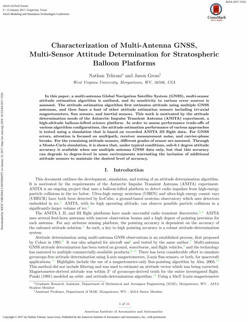
of precision (especially in polar regions) Furthermore adding inertial measurements Sun sensor and mag-netometer data further improves attitude-determination performance and reliability This simulation studywill be followed up with set of UAV flight test experiment Three GNSS receivers and antennas have beenmounted on a UAV platform as shown in Figure 9 along with a magnetometer Sun sensor and an IMU
Figure 9 WVU Phastball Zero UAV outfitted with GNSS receivers
This will allow for test and evaluation of the proposed algorithm using actual flight data which willinclude a high grade GNSSINS as a reference solution
Acknowledgments
This work was supported in part by NASA West Virginia Space Grant Consortium and the NationalGeospatial Intelligence Agency Academic Research Program grant HM0476-15-1-0004 Approved forNGA public release under case number 17-053
References
1Collaboration I et al ldquoEvidence for high-energy extraterrestrial neutrinos at the IceCube detectorrdquo Science Vol 342No 6161 2013 pp 1242856
2Hoover S et al ldquoObservation of Ultrahigh-Energy Cosmic Rays with the ANITA Balloon-Borne Radio InterferometerrdquoPhys Rev Lett Vol 105 Oct 2010 pp 151101
3Gorham P W et al ldquoObservational constraints on the ultrahigh energy cosmic neutrino flux from the second flight ofthe ANITA experimentrdquo Phys Rev D Vol 82 Jul 2010 pp 022004
4Gandilo N Ade P Amiri M Angile F Benton S Bock J Bond J Bryan S Chiang H Contaldi Cet al ldquoAttitude determination for balloon-borne experimentsrdquo SPIE Astronomical Telescopes+ Instrumentation InternationalSociety for Optics and Photonics 2014 pp 91452Undash91452U
5Cohen C E and Parkinson B W ldquoExpanding the performance envelope of GPS-based attitude determinationrdquo IONGPS-91 Proceedings of the 4th International Technical Meeting of the Satellite Division of the Institute of Navigation Vol 11991 pp 1001ndash1011
6Cohen C E and Parkinson B W ldquoAircraft applications of GPS-based attitude determinationrdquo Proceedings of the 5thInternational Technical Meeting of the Satellite Division of The Institute of Navigation (ION GPS 1992) 1992 pp 775ndash782
7Cohen C E Parkinson B W and McNally B D ldquoFlight tests of attitude determination using GPS compared againstan inertial navigation unitrdquo Navigation Vol 41 No 1 1994 pp 83ndash97
8Teunissen P J Giorgi G and Buist P J ldquoTesting of a new single-frequency GNSS carrier phase attitude determinationmethod land ship and aircraft experimentsrdquo GPS solutions Vol 15 No 1 2011 pp 15ndash28
9Magellan Professional ADU5 6 2007 Rev C
15 of 16
American Institute of Aeronautics and Astronautics
Dow
nloa
ded
by W
EST
VIR
GIN
IA U
NIV
ER
SIT
Y o
n Ja
nuar
y 10
201
7 | h
ttp
arc
aiaa
org
| D
OI
10
2514
62
017-
1554
10NovAtel ldquoAttitude-PitchRollYaw What We Offer httpwwwnovatelcomsolutionsattitudewhatWeOfferrdquo 11Crassidis J L and Markley F L ldquoPredictive Filtering for Attitude Estimation Without Rate Sensorsrdquo ADVANCES
IN THE ASTRONAUTICAL SCIENCES Vol 93 1996 pp 1021ndash103812Ahn H-S and Lee S-H ldquoGyroless Attitude Estimation of the Sun-Pointing Mode Satelliterdquo International Conference
on Control Automation and Systems October 2003 pp 22ndash2513Psiaki M L ldquoAutonomous low-earth-orbit determination from magnetometer and sun sensor datardquo Journal of Guid-
ance Control and Dynamics Vol 22 No 2 1999 pp 296ndash30414Toth C K and Grejner-Brzezinska D A ldquoPerformance analysis of the airborne integrated mapping system (AIMS)rdquo
International Archives of Photogrammetry and Remote Sensing Vol 32 1997 pp 320ndash32615GPSoft ldquoSatellite Navigation TOOLBOX 30 Userrsquos Guiderdquo 200316Watson R M Sivaneri V and Gross J N ldquoPerformance Characterization of Tightly-Coupled GNSS Precise Point
Positioning Inertial Navigation within a Simulation Environmentrdquo AIAA Guidance Navigation and Control Conference 2016p 1869
17Misra P and Enge P Global Positioning System Signals Measurements and Performance Second Edition LincolnMA Ganga-Jamuna Press 2006
18Gebre-Egziabher D Elkaim G H David Powell J and Parkinson B W ldquoCalibration of strapdown magnetometersin magnetic field domainrdquo Journal of Aerospace Engineering Vol 19 No 2 2006 pp 87ndash102
19Gross J N Gu Y and Rhudy M B ldquoRobust UAV relative navigation with DGPS INS and peer-to-peer radiorangingrdquo IEEE Transactions on Automation Science and Engineering Vol 12 No 3 2015 pp 935ndash944
20Teunissen P De Jonge P and Tiberius C ldquoThe lambda method for fast GPS surveyingrdquo International SymposiumGPS Technology Applications Bucharest Romania 1995
21Horn B K ldquoClosed-form solution of absolute orientation using unit quaternionsrdquo Journal of the Optical Society ofAmerica Vol 4 No 4 1987 pp 629ndash642
22Rhudy M and Gu Y ldquoUnderstanding Nonlinear Kalman Filters Part II An Implementation Guiderdquo InteractiveRobotics Letters 2013
23Stevens B L Lewis F L and Johnson E N Aircraft Control and Simulation Dynamics Controls Design andAutonomous Systems John Wiley amp Sons 2015
24Cojocaru S Birsan E Batrinca G and Arsenie P ldquoGPS-GLONASS-GALILEO a dynamical comparisonrdquo Journalof Navigation Vol 62 No 01 2009 pp 135ndash150
25Yoon S ldquoEuler angle dilution of precision in GPS attitude determinationrdquo Aerospace and Electronic Systems IEEETransactions on Vol 37 No 3 2001 pp 1077ndash1083
26Maine K Devieux C and Swan P ldquoOverview of IRIDIUM satellite networkrdquo WESCONrsquo95 ConferencerecordrsquoMicroelectronics Communications Technology Producing Quality Products Mobile and Portable Power Emerging Tech-nologiesrsquo IEEE 1995 p 483
27Blewitt G ldquoAn automatic editing algorithm for GPS datardquo Geophysical Research Letters Vol 17 No 3 1990 pp 199ndash202
16 of 16
American Institute of Aeronautics and Astronautics
Dow
nloa
ded
by W
EST
VIR
GIN
IA U
NIV
ER
SIT
Y o
n Ja
nuar
y 10
201
7 | h
ttp
arc
aiaa
org
| D
OI
10
2514
62
017-
1554
and a 0005 Sun sensor this method showed less than 01 error in all axes Crassidis (1996) created a Sunsensor and magnetometer Kalman filter and showed that a magnetometer-only attitude estimate is markedlyimproved (error reduced by approximately half) with the inclusion of Sun sensor data11 The Balloon-borneLarge Aperture Submillimeter Telescope for Polarimetry (BLASTPol) is a similar stratospheric platformthat uses Kalman filtering of multi sensor data for post-flight attitude determination4
Multi-antenna GNSS has been used for remote sensing platforms since shortly after its proposal14 andit is in use on multiple stratospheric balloon platforms4 This paper outlines the design and performanceevaluation of a GNSS-based attitude estimator that is then augmented with various other attitude sensorsto offer a proposed algorithm for the ANITA project or other similar balloon-based payloads
This remainder of this paper is organized as follows In Section II the simulation environment and thesensor data simulation is discussed In Section III the design of the baseline estimation filter and attitudeestimation filter are discussed Section IV the performance of the GNSS-based and multi-sensor attitudeestimators are presented and discussed Section V summarizes this studyrsquos findings and discusses futurework
II Data Simulation
IIA Flight Profile
The simulated flight data used in this study is based upon the recorded flight data of ANITA III That is tosimulate a balloon flight the onboard position and attitude solutions were accepted as truth for simulationpurposes and sensor readings with realistic measurement noise were simulated
0 1000 2000 3000 4000 5000 6000 7000
Time (s)
-08-06-04-02
Roll
(deg)
0 1000 2000 3000 4000 5000 6000 7000
Time (s)
0
05
1
Pitch (
deg)
1000 2000 3000 4000 5000 6000 7000
Time (s)
0
100
200
300
Yaw
(deg)
Figure 1 Attitude profile used in this work
Figure 1 shows the Euler angle time histories during a two-hour segment of the ANITA III flight Asindicated in Fig 1 the platform had a small (lt 1) oscillation in the roll and pitch axes and a constantrotation about the yaw axis
IIB GNSS Observables Simulation
For each simulation run four GNSS receivers were simulated with baseline separations of one-meter eachsuch that they are arranged in a square configuration That is the antennas were placed according to the
2 of 16
American Institute of Aeronautics and Astronautics
Dow
nloa
ded
by W
EST
VIR
GIN
IA U
NIV
ER
SIT
Y o
n Ja
nuar
y 10
201
7 | h
ttp
arc
aiaa
org
| D
OI
10
2514
62
017-
1554
following matrix Rb
Rb =
x2b y2b z2b
x3b y3b z3b
x4b y4b z4b
(1)
where xib yib and zib are the body-centric coordinates of the ith antenna i = 1 denoting the masterantenna as was done by Cohen in the first paper describing multi-antenna attitude determination5 GNSScarrier-phase data was simulated for each flight profile at a rate of 10 Hz using the MATLAB SatNavToolbox15 which was modified by Watson et al (2016)16 to include additional GNSS error sources
A number of deterministic and non-deterministic error sources are associated with GNSS measurements17
Fortunately for attitude estimation applications several of the primary GNSS error sources includingsatellite and receiver clock biases and atmospheric delays are canceled through the use of double differencedGNSS observations17 However two important error sources namely multipath reflections and carrier-phasebreaks (AKA cycle-slips) remain present In particular when a metallic object reflects a GNSS signalonto the antenna the multiple paths induce errors17 This could be a large problem on balloon-basedscientific platforms as the antennas are spaced closely and in close proximity to science payload Thermalmeasurement noise in the receiver is another error source it is actually amplified by double differencingGNSS data As such for this simulation study multipath carrier-phase breaks and receiver thermal errorswere assessed with respect to their effect on the attitude estimatorrsquos performance using the distributionsindicated in Table 1
IIC Inertial Measurement Simulation
In addition to GNSS measurements inertial measurement unit data was simulated for each flight profileand data at a sampling rate of 200 Hz In particular four grades of IMU tri-axial rate gyroscope andaccelerometers were simulated assessed In this case ideal gyroscope readings were generated by acceptingthe truth attitude solution of the ANITA III flight These ideal measurements were then polluted with botha time-varying bias and a white noise component The magnitude of these two noise terms were selectedbased on the grade of the inertial sensors assumed which were varied as indicated in Table 1
IID Sun Sensor amp Magnetometer Simulation
Two-axis Sun-sensor data and tri-axial magnetometer data were also simulated for each flight based onthe measurement models and uncertainties of the sensors current installed on the ANITA IV balloon Inparticular the apparent Sun position and the Earthrsquos magnetic field along the flight profile were calculatedand sensor measurements were simulated by polluting these true values with random noise based on themeasurement noises quoted by the manufacturersrsquo spec sheets as indicated in Table 1
The magnetometer data consists of magnetic field intensity measurements (Bb) in three orthogonal di-rections corresponding to the North N East E and down D axes in the body frame b This begins withBE a vector constraining the simulated magnetic field intensities in the navigation frame generated at eachlocation along the flight path
~BE =
BbN
BbE
BbD
(2)
Body-frame magnetic field measurements are generated by multiplying truth attitude (represented bythe direction-cosine matrix Cbn) by the navigation-frame magnetic field
~Bb = Cbn ~BE (3)
With three contributing error sources added hard and soft iron errors and measurement noise in asimplified method as described by Gebre-Egziabher et al18
B = Asi ~Bb + ~Bhi (4)
3 of 16
American Institute of Aeronautics and Astronautics
Dow
nloa
ded
by W
EST
VIR
GIN
IA U
NIV
ER
SIT
Y o
n Ja
nuar
y 10
201
7 | h
ttp
arc
aiaa
org
| D
OI
10
2514
62
017-
1554
where Asi is a 3times 3 matrix which describes the soft-iron error effect and ~Bhi is a 3times 1 vector containingthe hard-iron offset a magnetic field generated by ferromagnetic material on the platform For this studynominal values for Asi and ~Bhi were used based on the calibrations in the Gebre-Egziabher paper Simulatedmeasurement noise was then added to B corresponding to precision level of the modeled magnetometer
The simulated Sun sensor data consists of solar incidence angles 6 X and 6 Y relative to to the twohorizontal body-frame axes Xb and Yb These were generated using the apparent solar azimuth θSun andelevation φSun calculated for each epoch of the flight duration First the solar azimuth and elevation valuesare transformed into a unit vector representing the Sunrsquos position in the sky with respect to the navigationframe n
VSunn =
Sunxn
Sunyn
Sunzn
(5)
This unit-vector is then transformed using the nav-to-body direction cosine marix Cbn
VSunb = CbnVSunn (6)
and the solar incidence angles 6 X and 6 Y are then calculated
6 X = π2 + atan2(SunzbSunxb) (7)
6 Y = π2 + atan2(SunzbSunyb) (8)
where atan2 is the four-quadrant tangent inverseAs with the magnetometer measurements simulated measurement noise was added to the Sun sensor
measurements However in the case of a Sun sensor as measurement noise increases at low solar eleva-tions the measurement noise was scaled according to solar elevation angle Sun sensor measurements weresimulated at 10Hz intervals
IIE Simulation Overview
For this study a total of 50 one-hour flight profiles were simulated in a Monte-Carlo manner In particularthe ECEF starting positions magnitude of GNSS error sources and quality of IMU Magnetometer and Sunsensor data were varied as indicate in Table 1 Note that by randomly varying the starting location theGNSS constellation satellite geometry was randomized as well
III Attitude Estimation
IIIA Algorithm Overview
Figure 2 shows the overall algorithm used First a carrier-phase differential GNSS filter as detailed inSection IIIB estimates the baselines between antennas Next this information is used as a measurementupdate for a GNSS-only multiple antenna attitude estimator as described in Section IIIC in which theattitude estimates are smoothed by assuming typical low-dynamic balloon flights Finally the resultingestimated attitude state is optionally fused with a multi-sensor estimator that also incorporates inertialmagnetometer and Sun sensor data as discussed in Section IIID
4 of 16
American Institute of Aeronautics and Astronautics
Dow
nloa
ded
by W
EST
VIR
GIN
IA U
NIV
ER
SIT
Y o
n Ja
nuar
y 10
201
7 | h
ttp
arc
aiaa
org
| D
OI
10
2514
62
017-
1554
Table 1 Sensor Error-Source Monte-Carlo Simulation Distribution Parameters
Error-Sources Model Parameters Notes
Thermal Noise σρ = 032m σφ = 016λ linear scale factor randomly se-lected between [01]
Multipath 10 intensity σ = 04m τ = 15sec linear scale factor randomly se-lected between [02]
Tropospheric Delay Percent of error assumed handled by broad-cast correction
Modified Hopfield with linearscale factor randomly selectedbetween [095105]
Ionospheric Delay First order ionospheric effects mitigated withdual-frequency
linear scale factor randomly se-lected between [071]
Carrier phase break Likelihood set to 1 phase break per 24 minuteto 1 phase break per 240 minutes
Gyroscope In-run Bias σ = 96eminus6 radsec ARW = 02 degradichr
Scaled Honeywell HG1700AG72SF = ( 1
50 1200 1
400 )
Sun Sensor Zenith measurement noise σ = 01 deg Scaled SolarMEMS ISSDX-60SF = (1 2 3 4)
Magnetometer Measurement noise σ = 267 nTAsi terms scaled between [0005 001]~Bhi terms scaled between [25nT 50nT]
Scaled ST LSM9DS0SF = (1 5 10)
Figure 2 Block diagram showing the three main estimators baseline-estimation filter GNSS-only attitude estimatorand multi-sensor attitude estimator
IIIB Antenna Baseline Estimation Filter
A Kalman filter is used to estimate the relative position between each of the antennas and a single masterantenna at each of the 10 Hz measurement epochs In particular this Kalman filter uses Carrier-phase Dif-ferential GNSS (CD-GNSS) measurements to estimate the relative position vectors between the antennas17
The state vector x for this filter consists of the relative position vector components between antennarsquos A
5 of 16
American Institute of Aeronautics and Astronautics
Dow
nloa
ded
by W
EST
VIR
GIN
IA U
NIV
ER
SIT
Y o
n Ja
nuar
y 10
201
7 | h
ttp
arc
aiaa
org
| D
OI
10
2514
62
017-
1554
and B and a set of double-difference carrier-phase biases NAB
x =
xAB
yAB
zAB
N1kAB
N jkAB
(9)
The measurement models used to model the double-differenced carrier-phase observables follow the sameapproach outlined in19 as is discussed next
First the model for an undifferenced GNSS carrier-phase measurement φ (with units of carrier cycles)is given as17
φ = λminus1[r + Iφ + Tφ] +c
λ(δtu minus δts) +N + εφ (10)
where λ is the wavelength corresponding to the frequencies L1 and L2 and expressed in meters Thegeometric range r between the receiver and GNSS satellite is also expressed in meters as are the ionosphericand tropospheric delays I and T The speed of light c is expressed in meters per second The clock biases ofthe receiver and satellite δtu and δts respectively are expressed in seconds The un-modeled error sourceswhich include multipath and thermal noise are included in ε in units of meters
First carrier-phase measurements for the master antenna A (antenna 1) and B (antennas 2 3 or 4) aredifferenced to form single-differenced phase measurements
∆φjAB = λminus1rjAB +c
λδtAB +N j
AB + εjφAB (11)
Within Eq 11 due to the very short baseline separation between the antennas the atmospheric delayscompletely cancel along with the any satellite clock bias and ephemeris errors Next the single differencedmeasurements are then differenced between satellites For example between satellite j and a referencesatellite k
nabla∆φfjkAB = minusλminus1(1
macrjA minus 1
macrkA)T rABk|kminus1
+N jkAB + εjkφAB (12)
where the remaining receiver clock bias errors are eliminated leaving only the unknown phase bias N jkAB
which is known to be an integerWithin this filter the measurement vector z consists of double-differenced phase measurements for each
satellite relative to the reference satellite including measurements for each the L1 and L2 frequencies
z =[nabla∆φL1
inkAB nabla∆φL2
inkAB
] (13)
In parallel with this Kalman filter the floating point estimated phase bases N jkAB and their estimated
error-covariance are fed into and integer ambiguity resolution algorithm In particular the Least-squaresAMBiguity Decorrelation Adjustment (LAMBDA) method20 is used to determine the integer biases andadjust the estimated relative positions
IIIC GNSS-only Attitude Determination
Once the antenna relative baselines with respect to a master antenna are estimated using the baselineestimation filter an ECEF antenna relative position matrix RECEF is generated at each epoch by verticallyconcatenating the estimate relative vectors of each of non-master antenna as adopted from Cohen5
RECEF =
x2ECEF y2ECEF z2ECEF
x3ECEF y3ECEF z3ECEF
x4ECEF y4ECEF z4ECEF
(14)
6 of 16
American Institute of Aeronautics and Astronautics
Dow
nloa
ded
by W
EST
VIR
GIN
IA U
NIV
ER
SIT
Y o
n Ja
nuar
y 10
201
7 | h
ttp
arc
aiaa
org
| D
OI
10
2514
62
017-
1554
This matrix is then fed to a parallel estimator to estimate the platform attitude given the antenna baselinevectors in which the state vector x contains the attitude state expressed in Euler angles the represent therotation from the body to navigation-frame
x =
φ
θ
ψ
(15)
Using Hornrsquos Method21 the rotation matrix between body and Earth-fixed frames is found using theestimated the ECEF configuration RECEF and the known body-axis antenna configuration Rb Hornrsquosmethod is a variant of the sum of least squares21 where Rb and RECEF are both centered about theirrespective centroids yielding Rprimeb and RprimeECEF where a matrix M is equal to the product of the two centeredcoordinate matrices
M = Rprimeb lowastRprimeECEF (16)
The elements of this matrix are defined as follows
M =
Sxx Sxy Sxz
Syx Syy Syz
Szx Szy Szz
(17)
The matrix N is constructed using the elements from the above matrix
N =
(Sxx + Syy + Szz) Syz minus Szy Szx minus Sxz Sxy minus Syx
Syz minus Szy (Sxx minus Syy minus Szz) Sxy + Syx Szx + Sxz
Szx minus Sxz Sxy + Syx (minusSxx + Syy minus Szz) Syz + Szy
Sxy minus Syx Szx + Sxz Syz + Szy (minusSxx minus Syy + Szz)
(18)
The eigenvector V corresponding to the highest eigenvalue of N is normalized to form a unit quaternionand the imaginary component is omitted The resulting real quaternion is converted to a rotational matrixCEb the body-frame to Earth-frame transformation matrix which is in turn multiplied by the Earth-frameto navigation-frame transformation CnE This is converted into the measured Euler angles and the filterstate is updated
This filterrsquos measurement update consists of the Euler angles from the baseline vectors The error-statecovariance matrix P is initialized as a diagonal matrix containing the error magnitudes for each Euler anglein this case 01 The process noise matrix Q is set as the identity matrix as roll pitch and yaw rates arevery low for this platform
IIID Multi-Sensor Attitude Unscented Kalman Filter
Finally a third Kalman filter estimator is used for attitude determination using all sensor data In thisstep an unscented Kalman filter (UKF) was chosen for its ability to handle the nonlinear transformationbetween platform attitude and solar incidence angles in the Sun sensor measurements The details of theUKF implementation followed in this study are offered the tutorial paper by Rhudy and Gu22 and as suchthese details are not discussed in detail herein In this paper an outline of the state vector state predictionf(x) and observation functions h(x) for each measurement update are discussed
The state vector x estimated in the Multi-Sensor filter is given as
x =
φ
θ
ψ
bp
bq
br
(19)
where φ θ and φ are the platformrsquos roll pitch and yaw and bpqr are the time-varying biases of the IMUrsquosroll rate p pitch rate q and yaw rate r gyroscopes
7 of 16
American Institute of Aeronautics and Astronautics
Dow
nloa
ded
by W
EST
VIR
GIN
IA U
NIV
ER
SIT
Y o
n Ja
nuar
y 10
201
7 | h
ttp
arc
aiaa
org
| D
OI
10
2514
62
017-
1554
Within the UKF framework at each epoch the the state vector is expanded into a group of 2L+1 sigmapoints χ where L = 6 is the length of the estimated state vector For each group of sigma points l theattitude states are predicted by integrating the IMU gyro data through the attitude kinematic equations23
f(φ θ ψ)
φ i
θi
φi
=
φ iminus1
θiminus1
φiminus1
+
1 t(θiminus1)s(φiminus1) t(θiminus1)c(φiminus1)
0 c(φiminus1) minuss(φiminus1)c(θiminus1)
0 s(φ)c(θiminus1)
c(φiminus1)c(θiminus1)
pqr
minusbpbqbr
∆t
(20)
where s(middot) represents sine c(middot) represents cosine and t(middot) represents tangent Furthermore φiminus1 θiminus1 andψiminus1 are the previous epochrsquos roll pitch and yaw sigma points are the first three elements of each column ofχ and bpqr are the the sigma points corresponding to the IMU bias states which are predicted as randomwalk parameters
f(bpqr)
bpibqibri
=
bpiminus1bqiminus1
briminus1
+
wbpwbqwbr
(21)
The measurement-prediction matrix Ψ is populated by the predicted measurement vectors using each setof sigma-points in χ Because measurements occur at different rates in this filter it is necessary to havedifferent measurement updates occur at different rates For epochs coinciding with Sun sensor and GNSSattitude measurements each column Ψi is as follows
Ψi =
Bbx
Bby
Bbz6 X6 Y
φprime
θprime
ψprime
(22)
where Bb 6 X and 6 Y are predicted magnetometer and Sun sensor measurements based on the ith sigmapoint The observation models h(x) used to predict the magnetometer and Sen sensor measurements basedupon estimate attitude sigma points are identical to those used to generate the data as discussed in SectionII with the exception that no magnetometer biases are estimated in the filter That is the observationequations use Cbn the direction-cosine representation of the predicted attitude states φ θ and ψ
hB(φ θ ψ) ~Bb = Cbn ~Bn (23)
VSunb = CbnVSunn (24)
h6X
(φ θ ψ) 6 X = π2 + atan2(SunzbSunxb) (25)
h6Y
(φ θ ψ) 6 Y = π2 + atan2(SunzbSunyb) (26)
As GNSS attitude and Sun sensor measurements occur at at 10Hz rate the remaining (50Hz) measure-ment updates consist only of magnetometer measurement predictions
Ψi =
Bbx
Bby
Bbz
(27)
8 of 16
American Institute of Aeronautics and Astronautics
Dow
nloa
ded
by W
EST
VIR
GIN
IA U
NIV
ER
SIT
Y o
n Ja
nuar
y 10
201
7 | h
ttp
arc
aiaa
org
| D
OI
10
2514
62
017-
1554
The measurement update matrix z consists of the simulated sensor measurement at each filter epochThese are similar in form the the columns of Ψ
z =
Bbx
Bby
Bbz6 X6 Y
φGNSS
θGNSS
ψGNSS
(28)
for filter epochs with GNSS magnetometer and Sun sensor measurements and
z =
BbxBby
Bbz
(29)
for epochs with magnetometer measurements only
IIIE Assumed Stochastic Parameters
The Kalman filter process noise Q and measurement noise R and initial error-covariance P0 assumptionsselected for the differential GNSS baseline estimator are outlined in Table 2
Table 2 Baseline filter assumed parameters
Filter Parameter Assumed Values
State error covariance P0 Baseline states 1 m
Ambiguity states 225 m
Measurement noise covariance R σφ=4middot10minus4 m
Process noise covariance Q Attitude states In-run Bias middot10minus2 mradics
Ambiguity states 0 mradics
The multi-sensor unscented Kalman filter was developed to run in multiple modes (GNSS-inertial in-ertial magnetometer and Sun sensor only and all sensors) The different modes required different tuningparameters for adequate performance These are outlined in Table 3
Table 3 Multi-sensor attitude filter parameters
Filter Parameter Assumed Values
State error covariance P0 INS+Mag+SS 10minus2 deg attitude states 10minus6 deg bias states
INS+GNSS 10minus3 deg attitude states 10minus5 deg bias states
INS+all 10minus2 deg attitude states 10minus6 deg bias states
Measurement noise covariance R σMag=25nT
σSun=01 deg
σGNSS(φθ)=01 deg middotADOPσGNSS(ψ)=001 deg middotADOP
Process noise covariance Q Attitude states In-run Bias middot10minus2 radradics
Bias states ARW middot102 radradics
9 of 16
American Institute of Aeronautics and Astronautics
Dow
nloa
ded
by W
EST
VIR
GIN
IA U
NIV
ER
SIT
Y o
n Ja
nuar
y 10
201
7 | h
ttp
arc
aiaa
org
| D
OI
10
2514
62
017-
1554
IV Results
IVA Results Overview
To summarize the results of the Monte-Carlo study Figure 3 shows the cumulative distribution of the 3Dattitude error =
radicφ2 + θ2 + ψ2 for the various filter configurations over the 50 simulated flights As is
0 05 1 15 2
3D Attitude Error (deg)
0
01
02
03
04
05
06
07
08
09
1
Fra
ction o
f T
rials
CDF of 3D Attitude Error over 50 Trials
GPS-Only
GPS+GLONASS
GNSS+INS
GNSS+INS+Mag+SS
INS+Mag+SS
Figure 3 Comparison between GNSS-only filter and multi-sensor attitude filter in different modes (CDF truncated to2 degrees)
evident in Figure 3 in general the additional sensors yield improved performance Furthermore there is aclear advantage to adding GLONASS data into the estimator When all sensors are fused attitude estimationless than 02 degrees is available for approximately 75 of the data The CDF plot cuts off at two degreesas a small number of trials for which the filter diverged and are not shown for clarity
IVB GNSS-only Attitude Filter
The GNSS-only attitude filter was run in two modes the first using GPS data only and the second addingGLONASS observables The pitch roll and heading error statistics for both filter modes are presented inTables 4 and 5 These results include two simulations for which the baseline filter solution failed to convergepresumably due to carrier-phase break
Table 4 GPS-only Error Statistics
Roll
(deg)
Pitch
(deg)
Heading
(deg)
Min 00874 00867 00165
Max 1060718 404702 2218536
Mean 47867 15972 60898
Median 04281 04212 01611
10 of 16
American Institute of Aeronautics and Astronautics
Dow
nloa
ded
by W
EST
VIR
GIN
IA U
NIV
ER
SIT
Y o
n Ja
nuar
y 10
201
7 | h
ttp
arc
aiaa
org
| D
OI
10
2514
62
017-
1554
Table 5 GPS+GLONASS Error Statistics
Roll
(deg)
Pitch
(deg)
Heading
(deg)
Min 00405 00500 00112
Max 1036268 519286 3475524
Mean 48948 27352 115969
Median 02833 02661 00958
Using GLONASS as well as GPS satellites yielded a median performance improvement of 40 percentlower attitude error Considering ANITArsquos Antarctic flight regime fewer GNSS satellites are observableand these are seen at lower elevations24 This can negatively impact the Geometric Dilution of Precision(GDOP) a metric that describes the geometric diversity of satellite-receiver vectors17 The attitude dilutionof precision as proposed by Yoon (2001) is a similar metric which assesses the ability to measure Eulerangles25 It is defined as25
ADOP =radictr[(nI minus SST )minus1]
(30)
where n is the number of satellites in view I is the 3times3 identity matrix and S is a 3timesN matrix comprisingthe unit vectors to each satellite including the reference satellite25 A variable starting location was usedto investigate the effect of the lower GDOP and ADOP at high latitudes Figure 4 shows error performanceusing GPS satellites only and using both GPS and GLONASS satellites as well as the ADOP calculated ineach case for a polar flight profile
Figure 4 Comparison between GPS-only mode and GPS+GLONASS mode for a polar flight profile
IVC GNSS Multi-sensor Attitude Filter
Tables 6 7 and 8 present overall error statistics for the 50 trials (including the two convergence failures)for the GNSS+INS GNSS+ All sensors and All sensors without GNSS respectively The filter failed toconverge two times when the magnetic hard-iron bias was close to the magnetic process noise parameter inthe measurement covariance matrix
11 of 16
American Institute of Aeronautics and Astronautics
Dow
nloa
ded
by W
EST
VIR
GIN
IA U
NIV
ER
SIT
Y o
n Ja
nuar
y 10
201
7 | h
ttp
arc
aiaa
org
| D
OI
10
2514
62
017-
1554
Table 6 GNSS+INS Error Statistics
Roll
(deg)
Pitch
(deg)
Heading
(deg)
Min 00332 00339 00160
Max 1041555 519770 3475273
Median 01078 01064 00505
Table 7 GNSS+INS+Mag+SS Error Statistics
Roll
(deg)
Pitch
(deg)
Heading
(deg)
Min 00277 00220 00209
Max 614e+4 00189e+4 357e+4
Median 01078 01064 00505
Table 8 INS+Mag+SS Error Statistics
Roll
(deg)
Pitch
(deg)
Heading
(deg)
Min 00277 00220 00210
Max 979e+5 00012e+5 00032e+5
Median 00779 00723 00736
In these tables it is clear that that using additional sensors in addition to GNSS can markedly improveperformance For example Figure 5 shows the attitude estimation error for one example trial in which theGNSS-only attitude is shown alongside the multi-sensor filters for comparison
0 1 2 3 4 5
10 4
-1
0
1
Ro
ll E
rr
(de
g)
0 1 2 3 4 5
10 4
-1
0
1
Pitch
Err
(d
eg
)
0 1 2 3 4 5
Epoch 10 4
-1
0
1
Ya
w E
rr
(de
g)
GNSS-only
GNSS+INS
GNSS+INS+Mag+SS
Figure 5 Roll pitch and heading errors for multi-sensor filter in GNSS+INS mode GNSS+INS+Mag+SS mode withGNSS-only filter result for comparison
Of great interest is the algorithmrsquos ability to handle carrier-phase breaks For example phase breakscould occur due to radio-frequency interference such as during a data transmission over the Iridium satellite
12 of 16
American Institute of Aeronautics and Astronautics
Dow
nloa
ded
by W
EST
VIR
GIN
IA U
NIV
ER
SIT
Y o
n Ja
nuar
y 10
201
7 | h
ttp
arc
aiaa
org
| D
OI
10
2514
62
017-
1554
constellation which operates very close to the GPS L1 frequency26 When a carrier-phase break occurs itcan fortunately be detected easily by a data editor27 As such whenever this occurs the baseline estimationfilter re-sets the error-covariance for the impacted carrier-phase ambiguities to a large value The resultis a momentary spike in attitude error not longer than five filter time steps but often with multi-degreemagnitude The multi-sensor filter attitude determination performance was lower across the range of phasebreak likelihoods as shown in Figure 6 Notably the multi-sensor UKF yielded a low error-level attitudesolution for the two trials with GNSS-attitude convergence failure
0 02 04 06 08 1 12 14 16 18
Phase break likelihood (occurances s -1) times10-4
0
02
04
06
08
1
12
14
16
18
2R
MS
3D
attitude E
rror
(deg)
GNSS-only
GNSS+INS+Mag+SS
Figure 6 RMS attitude vs phase break likelihood for each trial
Also of interest is the filterrsquos performance with high receiver measurement thermal noise and multipatherrors Figures 7 and 8 show that the multi-sensor filter yields lower-magnitude errors than the GNSS-onlyfilter across both error scale ranges Although an increasing level of multipath error did not noticeably affectthe result of the GNSS-only filter performance the multi-sensor filter performed better in nearly all trials
The GNSS-only filter had a much greater sensitivity to the thermal error noise factor and the multi-sensor filter had a more-consistent error level for the thermal error range These plots do not include trialswhich failed to converge
13 of 16
American Institute of Aeronautics and Astronautics
Dow
nloa
ded
by W
EST
VIR
GIN
IA U
NIV
ER
SIT
Y o
n Ja
nuar
y 10
201
7 | h
ttp
arc
aiaa
org
| D
OI
10
2514
62
017-
1554
0 02 04 06 08 1
Thermal error scalar
0
02
04
06
08
1
12
14
16
18
2
RM
S 3
D a
ttitude E
rror
(deg)
GNSS-only
GPS+INS+Mag+SS
Figure 7 RMS attitude vs thermal error scalar for each trial
02 04 06 08 1 12 14
Multipath error scalar
0
02
04
06
08
1
12
14
16
18
RM
S 3
D a
ttitude E
rror
(deg)
GNSS-only
GPS+INS+Mag+SS
Figure 8 RMS attitude vs multipath error scalar for each trial
Sensitivity to the ionospheric and tropospheric error contribution to the GNSS errors was not consideredas the short baseline between antennas led to cancellation of those error sources
V Conclusion and Future Work
This study outlined the design and testing of a GNSS-based attitude determination algorithm as wellas its augmentation with additional sensor data GNSS-only attitude solutions are consistently improvedwhen GLONASS satellites are included in addition to GPS owing to more observables and lower dilution
14 of 16
American Institute of Aeronautics and Astronautics
Dow
nloa
ded
by W
EST
VIR
GIN
IA U
NIV
ER
SIT
Y o
n Ja
nuar
y 10
201
7 | h
ttp
arc
aiaa
org
| D
OI
10
2514
62
017-
1554
of precision (especially in polar regions) Furthermore adding inertial measurements Sun sensor and mag-netometer data further improves attitude-determination performance and reliability This simulation studywill be followed up with set of UAV flight test experiment Three GNSS receivers and antennas have beenmounted on a UAV platform as shown in Figure 9 along with a magnetometer Sun sensor and an IMU
Figure 9 WVU Phastball Zero UAV outfitted with GNSS receivers
This will allow for test and evaluation of the proposed algorithm using actual flight data which willinclude a high grade GNSSINS as a reference solution
Acknowledgments
This work was supported in part by NASA West Virginia Space Grant Consortium and the NationalGeospatial Intelligence Agency Academic Research Program grant HM0476-15-1-0004 Approved forNGA public release under case number 17-053
References
1Collaboration I et al ldquoEvidence for high-energy extraterrestrial neutrinos at the IceCube detectorrdquo Science Vol 342No 6161 2013 pp 1242856
2Hoover S et al ldquoObservation of Ultrahigh-Energy Cosmic Rays with the ANITA Balloon-Borne Radio InterferometerrdquoPhys Rev Lett Vol 105 Oct 2010 pp 151101
3Gorham P W et al ldquoObservational constraints on the ultrahigh energy cosmic neutrino flux from the second flight ofthe ANITA experimentrdquo Phys Rev D Vol 82 Jul 2010 pp 022004
4Gandilo N Ade P Amiri M Angile F Benton S Bock J Bond J Bryan S Chiang H Contaldi Cet al ldquoAttitude determination for balloon-borne experimentsrdquo SPIE Astronomical Telescopes+ Instrumentation InternationalSociety for Optics and Photonics 2014 pp 91452Undash91452U
5Cohen C E and Parkinson B W ldquoExpanding the performance envelope of GPS-based attitude determinationrdquo IONGPS-91 Proceedings of the 4th International Technical Meeting of the Satellite Division of the Institute of Navigation Vol 11991 pp 1001ndash1011
6Cohen C E and Parkinson B W ldquoAircraft applications of GPS-based attitude determinationrdquo Proceedings of the 5thInternational Technical Meeting of the Satellite Division of The Institute of Navigation (ION GPS 1992) 1992 pp 775ndash782
7Cohen C E Parkinson B W and McNally B D ldquoFlight tests of attitude determination using GPS compared againstan inertial navigation unitrdquo Navigation Vol 41 No 1 1994 pp 83ndash97
8Teunissen P J Giorgi G and Buist P J ldquoTesting of a new single-frequency GNSS carrier phase attitude determinationmethod land ship and aircraft experimentsrdquo GPS solutions Vol 15 No 1 2011 pp 15ndash28
9Magellan Professional ADU5 6 2007 Rev C
15 of 16
American Institute of Aeronautics and Astronautics
Dow
nloa
ded
by W
EST
VIR
GIN
IA U
NIV
ER
SIT
Y o
n Ja
nuar
y 10
201
7 | h
ttp
arc
aiaa
org
| D
OI
10
2514
62
017-
1554
10NovAtel ldquoAttitude-PitchRollYaw What We Offer httpwwwnovatelcomsolutionsattitudewhatWeOfferrdquo 11Crassidis J L and Markley F L ldquoPredictive Filtering for Attitude Estimation Without Rate Sensorsrdquo ADVANCES
IN THE ASTRONAUTICAL SCIENCES Vol 93 1996 pp 1021ndash103812Ahn H-S and Lee S-H ldquoGyroless Attitude Estimation of the Sun-Pointing Mode Satelliterdquo International Conference
on Control Automation and Systems October 2003 pp 22ndash2513Psiaki M L ldquoAutonomous low-earth-orbit determination from magnetometer and sun sensor datardquo Journal of Guid-
ance Control and Dynamics Vol 22 No 2 1999 pp 296ndash30414Toth C K and Grejner-Brzezinska D A ldquoPerformance analysis of the airborne integrated mapping system (AIMS)rdquo
International Archives of Photogrammetry and Remote Sensing Vol 32 1997 pp 320ndash32615GPSoft ldquoSatellite Navigation TOOLBOX 30 Userrsquos Guiderdquo 200316Watson R M Sivaneri V and Gross J N ldquoPerformance Characterization of Tightly-Coupled GNSS Precise Point
Positioning Inertial Navigation within a Simulation Environmentrdquo AIAA Guidance Navigation and Control Conference 2016p 1869
17Misra P and Enge P Global Positioning System Signals Measurements and Performance Second Edition LincolnMA Ganga-Jamuna Press 2006
18Gebre-Egziabher D Elkaim G H David Powell J and Parkinson B W ldquoCalibration of strapdown magnetometersin magnetic field domainrdquo Journal of Aerospace Engineering Vol 19 No 2 2006 pp 87ndash102
19Gross J N Gu Y and Rhudy M B ldquoRobust UAV relative navigation with DGPS INS and peer-to-peer radiorangingrdquo IEEE Transactions on Automation Science and Engineering Vol 12 No 3 2015 pp 935ndash944
20Teunissen P De Jonge P and Tiberius C ldquoThe lambda method for fast GPS surveyingrdquo International SymposiumGPS Technology Applications Bucharest Romania 1995
21Horn B K ldquoClosed-form solution of absolute orientation using unit quaternionsrdquo Journal of the Optical Society ofAmerica Vol 4 No 4 1987 pp 629ndash642
22Rhudy M and Gu Y ldquoUnderstanding Nonlinear Kalman Filters Part II An Implementation Guiderdquo InteractiveRobotics Letters 2013
23Stevens B L Lewis F L and Johnson E N Aircraft Control and Simulation Dynamics Controls Design andAutonomous Systems John Wiley amp Sons 2015
24Cojocaru S Birsan E Batrinca G and Arsenie P ldquoGPS-GLONASS-GALILEO a dynamical comparisonrdquo Journalof Navigation Vol 62 No 01 2009 pp 135ndash150
25Yoon S ldquoEuler angle dilution of precision in GPS attitude determinationrdquo Aerospace and Electronic Systems IEEETransactions on Vol 37 No 3 2001 pp 1077ndash1083
26Maine K Devieux C and Swan P ldquoOverview of IRIDIUM satellite networkrdquo WESCONrsquo95 ConferencerecordrsquoMicroelectronics Communications Technology Producing Quality Products Mobile and Portable Power Emerging Tech-nologiesrsquo IEEE 1995 p 483
27Blewitt G ldquoAn automatic editing algorithm for GPS datardquo Geophysical Research Letters Vol 17 No 3 1990 pp 199ndash202
16 of 16
American Institute of Aeronautics and Astronautics
Dow
nloa
ded
by W
EST
VIR
GIN
IA U
NIV
ER
SIT
Y o
n Ja
nuar
y 10
201
7 | h
ttp
arc
aiaa
org
| D
OI
10
2514
62
017-
1554
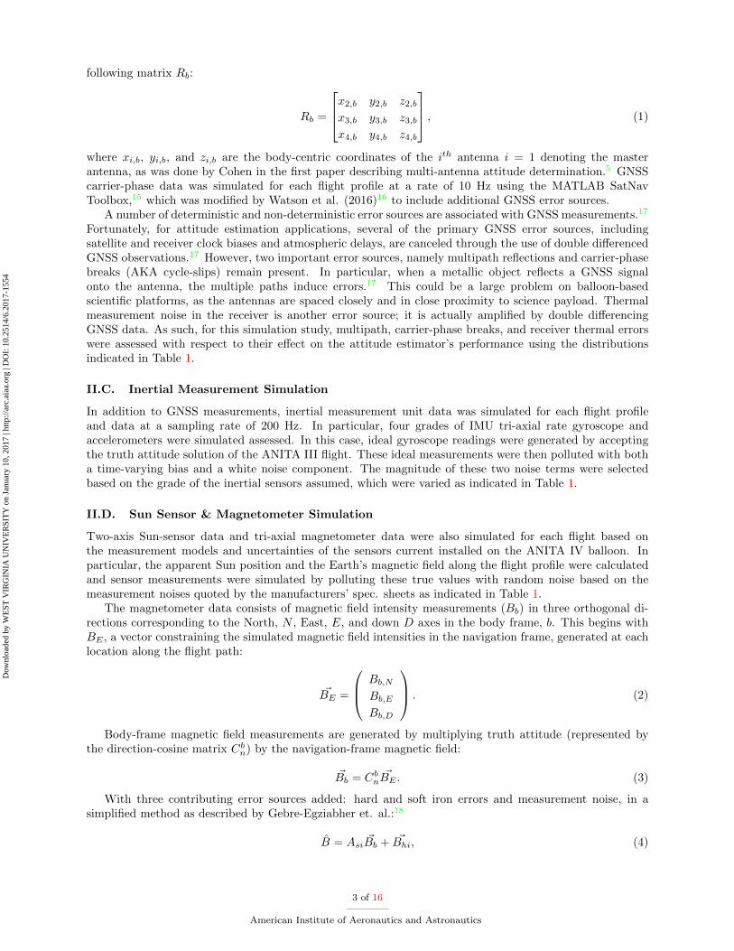
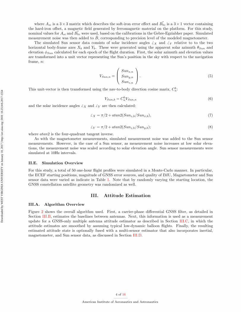
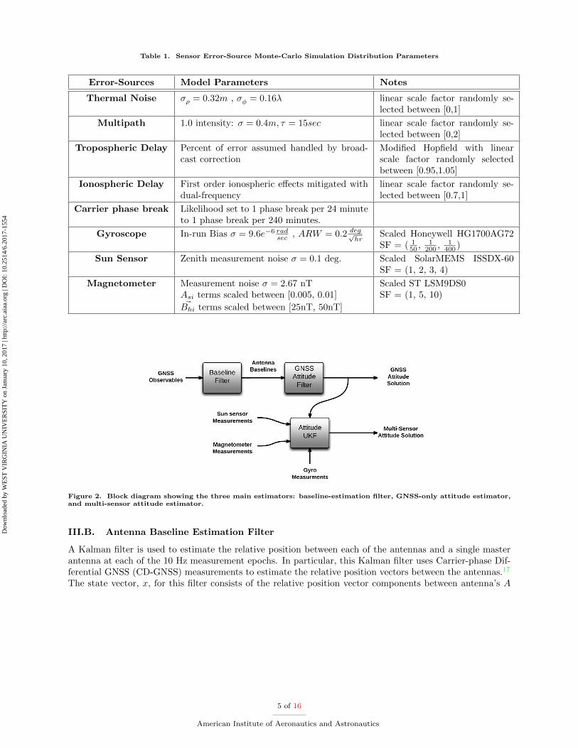
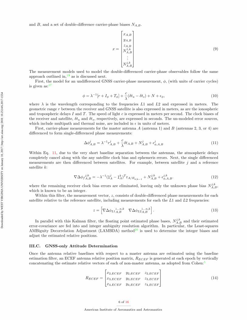
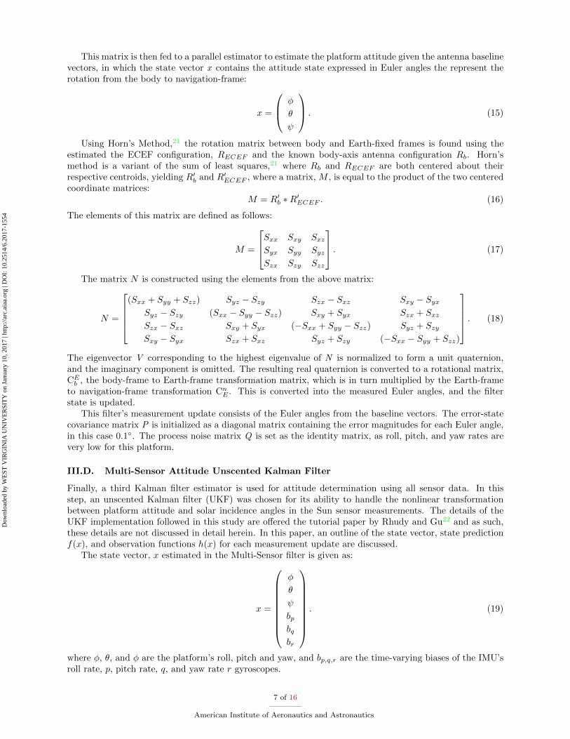
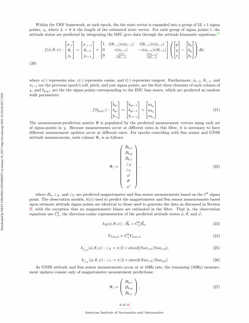
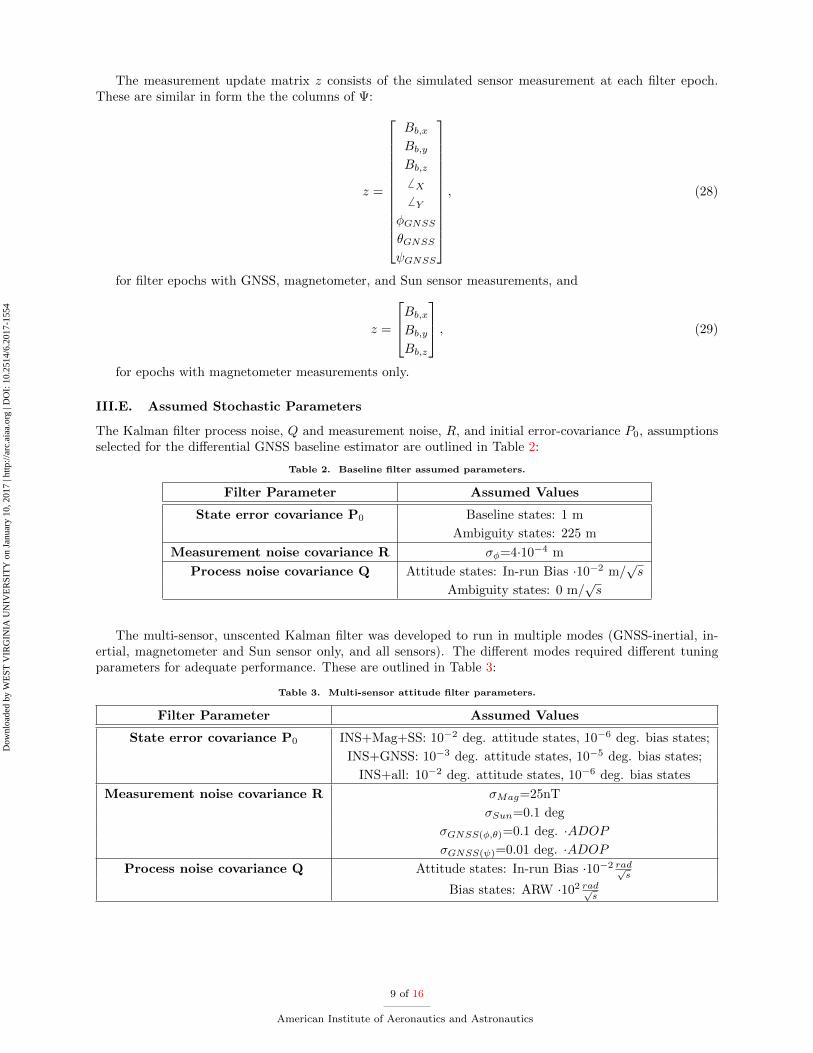
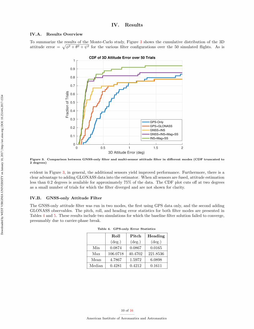
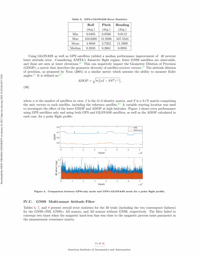
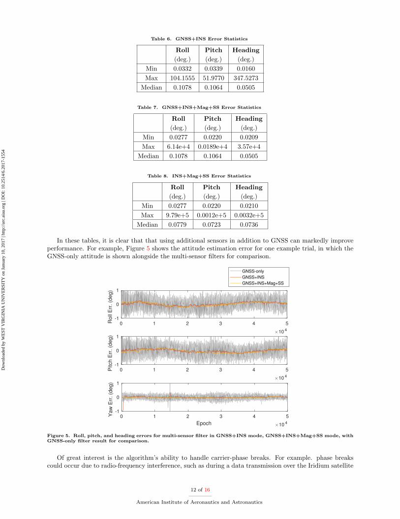
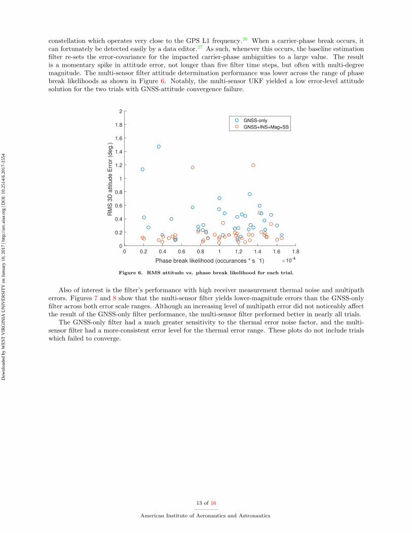
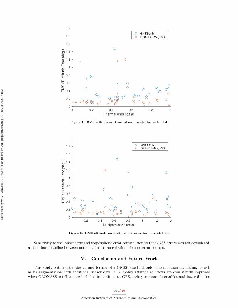
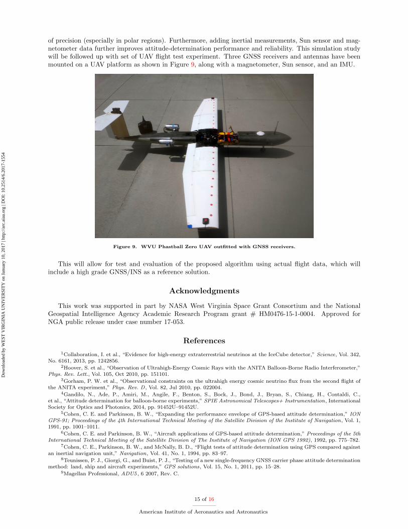
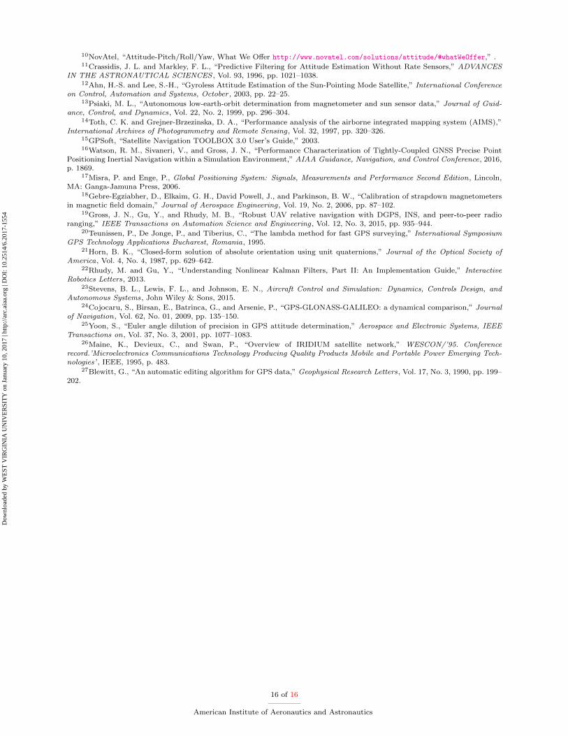