Embed Size (px)
Citation preview
FIXED LINE ACCESSISSUE-III: MARCH.2014
______________________________________________________________________________
CHARACTERIZATION OF VRLA BATTERIES AND GUIDELINES FOR THE O&M OF VRLA BATTERIES
GL No.TEC/GL/TX/BAT-04/03/March.2014(This document supersedes previous documents ‘Monitoring of VRLA Batteries Guidelines
No. GL/BAT-004/02 MAR 2007’)
© TEC
TELECOMMUNICATION ENGINEERING CENTREKHURSHIDLAL BHAWAN, JANPATH,
NEW DELHI-110001 (INDIA)______________________________________________________________________________
All rights are reserved and no part of this publication may be reproduced, stored in any retrieval system, or transmitted, in any form or by any means, electronic, mechanical, photocopying, recording, scanning or otherwise without written permission from the Telecommunication Engineering Centre, New Delhi-110001.______________________________________________________________________________
ISO 9001: 2008
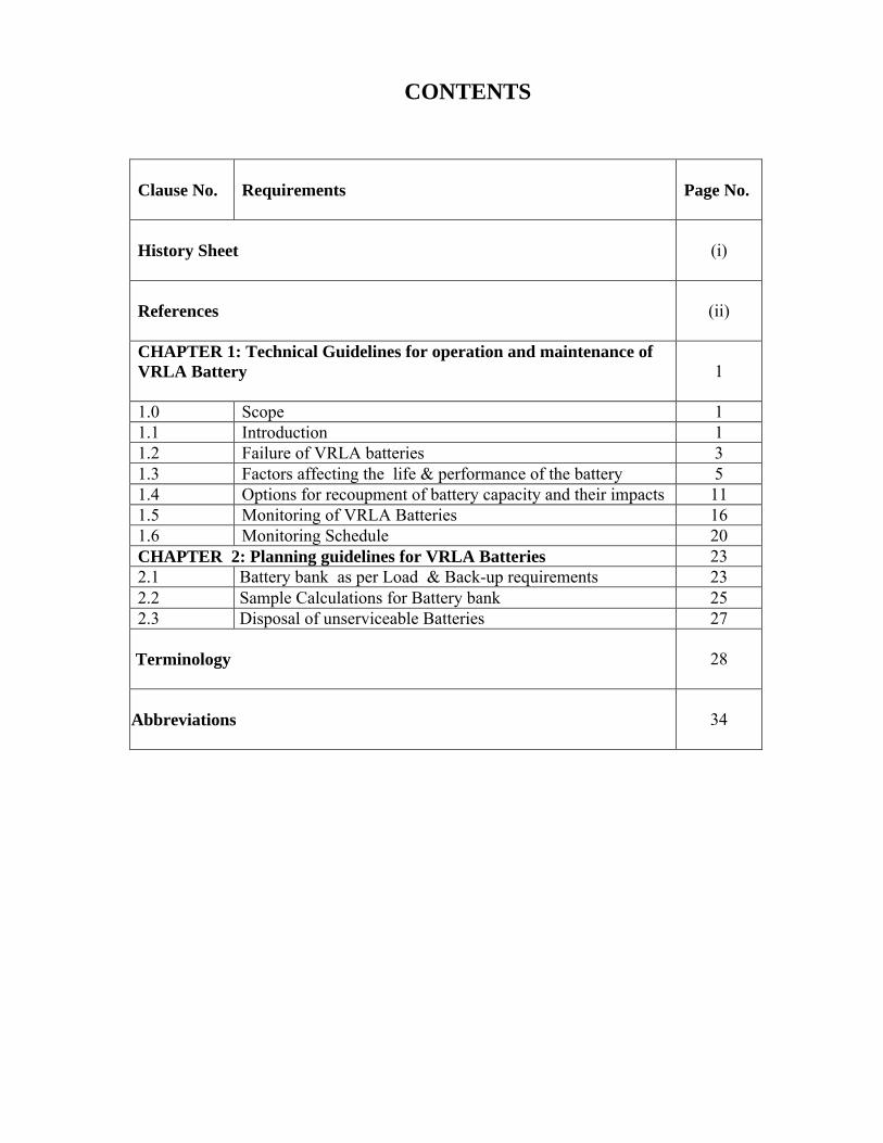
CONTENTS
Clause No. Requirements Page No.
History Sheet (i)
References (ii)
CHAPTER 1: Technical Guidelines for operation and maintenance ofVRLA Battery 1
1.0 Scope 11.1 Introduction 11.2 Failure of VRLA batteries 31.3 Factors affecting the life & performance of the battery 51.4 Options for recoupment of battery capacity and their impacts 111.5 Monitoring of VRLA Batteries 161.6 Monitoring Schedule 20CHAPTER 2: Planning guidelines for VRLA Batteries 232.1 Battery bank as per Load & Back-up requirements 232.2 Sample Calculations for Battery bank 252.3 Disposal of unserviceable Batteries 27
Terminology 28
Abbreviations 34
i
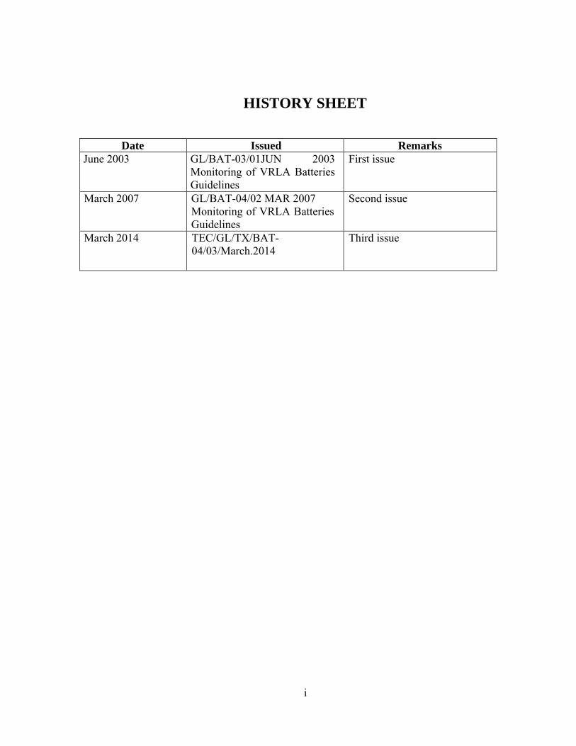
HISTORY SHEET
Date Issued RemarksJune 2003 GL/BAT-03/01JUN 2003
Monitoring of VRLA Batteries Guidelines
First issue
March 2007 GL/BAT-04/02 MAR 2007Monitoring of VRLA Batteries Guidelines
Second issue
March 2014 TEC/GL/TX/BAT-04/03/March.2014
Third issue

ii
iii
REFERENCES
1. BIS 1651: Stationary cells and batteries.
2. BIS 1554 with amendment-I (1994): Fire Retardant Cables.
3. TEC/GR/TX/BAT-001/04.June.2011 with amendments: VRLA Batteries
4. TEC/GR/TX/BAT-02/03/Dec.2013 with amendments, if any: VRLA Batteries for High Rate of Discharge (UPS Application)
5. TEC/GR/TX/BAT-003/02.MAR.2011 with amendments: Tubular VRLA Batteries based on GEL Technology.
6. TEC/GR/FLA/SMP-001/06.JUN.2010 with amendments: SMPS based Power Plants.
7. Maintenance free Batteries by D Berndt.
8. Battery Reference Book by T.R. Crompton.
9. Modern Battery Technology Edited by Clive D.S. Tuck.
10. Battery Technology Hand-book Edited By H.A. Kiehne.
11. QM-333: Specification for Environmental Testing of Electronic Equipments for Transmission and Switching use.
12. QM-115: Quality standard for calculation/verification of MTBF
13. IS 1554 with amendment-1 (June 1994): Standard for Cables & Wires
14. ITU-T Rec. 0.41: Psophomeric noise requirements.
15. www.batteryuniversity.com

Page 1
Page 2
CHARACTERIZATION OF VRLA BATTERIES AND GUIDELINES
FOR THE O&M OF VRLA BATTERIESNo. TEC/GL/TX/BAT-04/03/March.2014
CHAPTER 1
TECHNICAL GUIDELINES
1.0 Scope: This document covers the basic theory and concept of VRLA Batteries technology. It also covers the necessary guidelines for monitoring & planning of the Batteries for a given telecom equipment. These guidelines have detailed the facts which should be taken into consideration while selecting a battery for a given requirement. It has also given the guidelines for calculating load for a given system. Sample calculation for deciding the load and Batteries have also been incorporated in this document to elaborate the guidelines for the user.
1.1 Introduction: The battery is an important constituent of the Telecom Network for sustaining the trouble free and uninterrupted service to its users. Till 1994, the whole of the Indian Telecom Network relied wholly on flooded type batteries to provide the necessary power back-up.
In the initial stages of standby power source, flooded flat-pasted type batteries were used in the Indian telecom network. Later on flooded tubular positive plates batteries were used. All these batteries were being procured and tested as per respective IS standard IS-1650. The certification of these batteries was being done by QA wing of DoT (presently BSNL).
Moreover, the Conventional lead acid (flooded type) batteries which were being used in the department were bulky and required a separate battery room with exhaust fans to throw out the acid fumes emitted by these batteries. Flooded batteries cannot be transported in charged condition, hence assembly and charging at site is essential. These batteries also require periodical special charging process at comparatively higher voltage of 2.7 V/cell (a total voltage of 65 V), also known as boost-charging, to agitate the electrolyte thoroughly to prevent stratification of electrolyte, as well as to reduce sulphation of plates. As the telecom equipment cannot withstand such a high voltage, the battery under boost-charging and the charger have to be isolated from the exchange equipment. Maintenance of these batteries needs more efforts and is more labour oriented. Moreover, it will be more difficult for the flooded batteries to meet the pollution norms, issued by Ministry of Environment and Forest.
In 1994, the VRLA batteries were introduced in Indian Telecom Network for the first time. Since then, the Department has been procuring VRLA batteries for the purpose. This is because of the fact that these batteries do not require the rigid routine maintenance like periodic topping up, recording Specific Gravity (SG) of each cell and periodic discharge/charge cycles.
Page 3
VRLA batteries require very little maintenance that is why they are confused as “maintenance free batteries”. These batteries emit extremely low amount of gases and do not require periodic toping up. Hence, they can be installed in the equipment room itself, thus saving the manpower and long connecting bus-bar or cables. Plates of these batteries have a higher current density, hence have a small size. As these batteries are based on starved electrolyte principal, can be installed in any orientation. All the above characteristics make VRLA batteries ideal stand by power source for Telecom applications.
But VRLA batteries have their own problems and limitations, which require timely and intelligent handling. Some of the constraints are: -
1.1.1 Self Discharge: These VRLA batteries are supplied in charged condition, but cells/batteries get discharged of its own due to its internal resistance and some localised action within the cells. This is termed as self-discharge. Self-discharge of these cells/batteries is about 4 percent every four weeks.
If these cells/batteries are allowed to remain in storage for a long period of time, say, 3 months or more, the sulphation of the plates starts setting in. More the time it is allowed to remain in this state, more the sulphation gets hard and more it becomes difficult to remove it from cells/batteries. Therefore, it is essential that these cells/batteries are commissioned in the least possible time so that self-discharge and subsequent sulphation is kept to minimum.
The following is recommended so as to avoid self-discharge due to long storage periods.
Recommendations:The cumulative self-discharge over a period of 6 months, at an average temperature of 35° Centigrade should be below 50% (for AGM Batteries) or 25% (for GEL Batteries) of its rated capacity. So, it is essential that the battery should be commissioned within the shortest possible time and a storage period of more than three months should be avoided. In case of storage period of more than 6 months, the supplementary charge should preferably be given to the batteries after every 3 months to keep the batteries in healthy condition.
1.1.2 Paralleling of cells: The highest capacity of single cell available for AGM/Tubular VRLA batteries based on Gel technology is 1500AH. To achieve the higher capacity paralleling of cell is essential.
Effect: If the cells are not properly matched, premature failure of cell may take place.
The following is recommended while putting the cells in parallel:
Recommendations: i) Number of paralleling of cell is restricted to four.ii) For paralleling, cells below 1000 AH should not be permitted.iii) Cell/Cell module matching for capacity, voltage and Conductance should be
Page 4
necessary.
1.1.3 Charging Techniques: A special charging technique is required to ensure that charging does not result in temperature rise in the cells.
Therefore, the following is recommended:
Recommendations:i) A constant voltage technique with battery path current limited to C/3.33 should
be used.ii) Float and charge voltages should be 2.25 V/Cell and 2.30V/Cell respectively.
It is advised not to resort to fast charging by setting higher Float/charge voltages.
1.2 Failure of VRLA batteries: Most common reasons for the failure of VRLA batteries are described below: -
1.2.1 Positive grid corrosion and Softening of active material: Every time the battery discharges, PbO2 of the +ve plate gets converted into PbSO4, there is a large increase in its volume, which puts pressure on the paste. Deeper the discharge, more is the increase in the volume of the paste of the positive plate and more is the pressure on the grid.
During charge the paste of the +ve gets converted back into PbO2 the paste gets contracted.
This expansion and contraction results in loosening of the active material in the grid over a period of time. This results in loss of contact of the active material with the +ve plate and increase in the cell resistance. This is a gradual process and under normal circumstances is a sign of ageing, which should only take place when the battery has lived its stipulated life.
In addition to ageing there are other factors which accelerate the process and lead to premature ageing. Some of them are: -
1. Larger the number of charge/discharge cycles, faster the ageing process.2. Deeper the discharge faster the ageing.3. Fast rate of Charging.4. Fast rate of Discharging.
The batteries cannot be recovered because of this corrosion and it indicates the end of the life of the cell.
1.2.2 Sulphation: Sulphation of the cells plates due to prolonged under charge (Prolonged undercharge/Partial state of charge operation) or prolonged storage will also increase the cell resistance. This is a recoverable damage unless the sulphation is hard enough to remove and it can only be recovered by careful and controlled charging of the cell.
Page 5
In case the sulphation is soft (not very thick), the same may be recovered through careful & controlled charging as per manufacturer’s recommendations. In such cases, a few charge/discharge cycles are required for the optimum recovery. This may be achieved preferably on site by cycling the cell keeping in battery bank or removing the cell from battery bank and reconditioning, giving controlled charging as per manufacturer’s recommendations.
In case the sulphation becomes too hard to revive, the cell should be concluded as damaged beyond repair.
1.2.3 Dry out (loss of electrolyte): There is a misconception that these batteries are fully sealed and no escape of gasses takes place. However, the gasses escape through the safety valve to maintain the pressure within cells in prescribed limits and therefore, most common mode of failure of the cell/battery is dry out. This may happen due the excessive escape of gasses from the cell, which leaves the cell with little or no electrolyte. This may happen due to:
(a) Fast Charging (Charging at higher voltage & current than recommended)(b) Operation of the battery at a very high temperature(c) Leakage through cracks in the container or sealing.(d) Not applying temperature compensation to charge voltage when operating
temperature is higher than the designed.
The indications for above failure is increase in the internal resistance of the cell or resistance of the battery.
1.2.4 Abrupt Failure: Due to lack of proper monitoring schedule, the cells with high resistance are not detected in time. In such cases, when the battery is put on load, it fails to take the load. The two main reasons in such cases are: -
a) Improper or Loose inter-cell connections: In case the inter-cell connectors are under rated/not connected firmly, the cell will get excessively heated up and may affect the sealing, resulting in cracks, which in turn lead to escape of gasses and dry out.
b) Increase in the internal resistance of the cell/cells: This may be caused by sulphation or corrosion of the plates. Abrupt failure will only occur, when the corrosion is severe i.e. at the verge of breaking.
1.2.5 Low capacity Failure: This failure may mainly be attributed due to the ageing. As the battery ages, it starts losing its capacity. If the battery capacity falls below the 80% of its rated capacity, it is presumed to have lived its life. Ageing is very slow process in initial stages of decay and gains speed only when it nears 80% of its rated value. If the capacity of any cell/battery is approaching it requires immediate replacement.
N.B.: It may be mentioned here that both of the above Abrupt and Low capacity failures can be detected well in advance (unless the cells cracks or sealing gets open due to sustained high terminal temperature), by observing a few indicators
Page 6
which can alarm about the failure tendency of a cell or the battery, because decaying of cell or battery is a gradual process and can be detected much in advance.
1.2.6 Thermal Runaway: VRLA Batteries are very temperature sensitive. The chemical reaction increases/decreases in geometric progression with the increase or decrease in temperature. In case of VRLA batteries, the operating temperature is very significant because of limited volume of electrolyte which restricts the heat conduction.
Thermal Runway occurs when more heat is generated within the battery than can be dissipated through its case into the environment. Heat is generated internally by exothermic chemical reactions from excessive charge current pumped into the battery. This increase in current is primarily in response to the increased rate of oxygen generation at the positive plate & resulting increase in the recombination rate at the negative plate. The increased rate of oxygen recombination will increase the rate of heat generation. If the battery cannot reject as much heat as it generates, its internal temperature rises.
This mechanism can go out of control if the rate of increase of generation of heat is greater than the rate of increase of dissipated heat and eventually VRLA battery temperature rises until the cells dry out & the container softens, ruptures & melts.
The propensity for thermal runway depends not only on the battery’s applied changing voltage maximum charge current & its surrounding thermal environment (ambient temperature & air circulation) but also on other factors such as battery design, construction, state of health & insufficient battery cooling.Therefore, to avoid thermal runaway, the following is recommended:
Recommendations:i) The user should ensure that all the features of SMPS Power Plants such as
battery path current limiting, temperature compensation of the battery, high voltage cut-off and precise voltage setting in the Power Plant are fully functional and properly set.
ii) The user should ensure that the ambient temperature of the battery room has been reduced by employing the natural air convection (ventilated room) with exhaust fan.
1.3 Factors affecting the life & performance of the battery: Some of the common factors which cause the premature failure and affecting the life & performance of the battery are:a) Deep discharge and insufficient rechargeb) Improper Chargingc) No Temperature controld) Cell Matchinge) Storage of batteries for extended period without supplementary chargef) Improper installationg) Manufacturer Problemsh) Operational/Maintenance issues.
Page 7
1.3.1 Battery Discharge:
1.3.1.1 Deep discharge of the battery: It is a universal fact that deeper the battery is discharged, lesser the life of the battery we get. Moreover, it is not recommended to discharge the battery beyond 80% of its rated capacity as it affects the expected life of the battery severely. This can be understood by the fact that an exchange battery when discharged to 20% of its rated capacity, may give up to 3000 such cycles. Same battery when discharged to 50% of its rated capacity it may give about 1800 such cycles and will give only 1400 cycles if discharged to 80% of its capacity. The same battery if discharged to its full rated capacity may only give about 600 such cycles only.
Recommendations: Therefore, it is recommended that the battery should not be allowed to discharge beyond 80% of its rated capacity.
1.3.1.2 Frequent discharge or Excessive cycles: As already explained under the heading Grid corrosion, the cycling affects the life of the cell/battery.
Under ideal conditions i.e. moderate ambient temperature (10°C to 35°C), charging not faster than C/3.33 rate, and compatible charger, a telephone exchange battery, on true float may give about 15 years of its service life, the same battery in cyclic discharge application with 80% DOD (Depth of discharge) will give only 1400 cycles i.e. four year of life approximately. The battery application in Indian Telecom Network is neither of the two extreme categories. So more the deep discharge cycles/year, lesser the expected life of the battery.
Foe better performance and service life of the battery, the following is recommended: -
Recommendations: Battery should not be allowed to discharge beyond 80% of its rated capacity. Each & every battery discharge should be properly logged. This will help to have a good idea about the health and remaining life of the battery.
1.3.1.3 Discharging of Batteries at faster rate: The faster rate of discharge of a battery lowers its rated capacity. For example, discharging battery at C/3.33 rate of discharge will give 71.7% of rated capacity.
Therefore, the following is recommended to avoid the discharge at fast rates:
Recommendations: i) The batteries in exchange/transmission & other similar application should be
so chosen that they are not allowed to discharge faster than C/6.ii) Where faster discharge (C/0.5 to C/5) is an essential requirement, as in the
case of UPS systems etc., the battery may be planned with the lower expected life as per the rate of discharge. The VRLA Batteries for High Rate
Page 8
of Discharge (UPS Application) vide GR No. TEC/GR/TX/BAT-02/03/Dec.2013 be used in such cases.
1.3.2 Improper Charging: VRLA batteries, being starved electrolyte type are more sensitive to temperature. The charge rate depends on the voltage and temperature of the electrolyte. Temperature, on the other hand, also depends on the charging voltage. It is clear that all the three parameters are interdependent. It becomes very essential that proper balance between three is achieved. Therefore, these batteries are required to be charged at precise voltage to prevent the overcharging or under charging of the battery. Moreover, the open circuit of AGM and GEL VRLA batteries is higher (2.11 to 2.17 V) than conventional flooded load acid batteries (2.01 to 2.07 V), hence the power plant designed for flooded batteries are not suitable for AGM and GEL VRLA batteries.
1.3.2.1 Under Charged Battery: Under-charging leads to sulphate crystal formation on the plates. In case sufficient current is not allowed to flow through it, the sulphation gets harder and harder, consequently it becomes difficult to break such sulphation. This will lead to loss of active material from the negative plate.
In case the battery is kept in under- charged condition for a long time, it loses its rated capacity due to sulphation. If the sulphation becomes very hard, it would be difficult to recover the battery.
The following may be ensured to avoid the battery being under charged
Recommendations: i) The power plant should be compatible with VRLA batteries & should have
enough capacity to take care of load and battery at C/3.33 rate of charge.ii) The float & charge voltages should be as per battery manufacturer’s
instructions.iii) At the time of installation/commissioning of the battery, the battery should be
fully charged before putting on load.
1.3.2.2 Over-Charging of Batteries: Over-charging causes excessive gassing of hydrogen and oxygen. This leads to the frequent opening of the valve to release the internal pressure and consequent result is drying out of the cells. It will also increase the temperature of the cell, which is not desired for VRLA battery, because high uncontrolled temperature may lead to thermal runway. Moreover, excessive charging accelerates grid corrosion.
The charging of VRLA battery at too high rate severely affects its performance & life. The two main factors which cause over- charging are higher battery temperature and higher float/charge voltage.
Therefore, the following should be ensured to prevent the batteries from over charging:
Recommendations: i) Float & Charge voltages at 27°C should be set at 2.25 V/cell & 2.30 V/cell
respectively. Change-over from float to charge & vice-versa should be
Page 9
automatic in the SMPS power plants as per TEC GR No TEC/GR/FLA/SMP-001/06/JUN.2010 with amendments.
ii) The battery temperature compensation in the power plant should be fully functional & all the terminations should be in proper place.
iii) Though not mandatory, it is advisable that the batteries should be placed in cooler environment for longer life and better performance.
vi) Set the battery path current in the power plant so that battery path current for each battery in the battery bank is restricted to 30% of the battery capacity.
1.3.3 Temperature Effect: As already indicated in clause 1.2.6, batteries are very temperature sensitive. The kinetics of these batteries is temperature dependent. The chemical reaction increases/decreases in geometric progression with the increase or decrease in temperature. In case of VRLA batteries, the temperature is significant because of the limited volume of electrolyte which restricts heat conduction. In the light of this fact, the proper temperature is essential for the optimization of battery life. Internationally the batteries are designed at 27˚C. The recombination of gases within a VRLA cell can only take place at a certain temperature. If the temperature is exceeded, gas pressure will build up beyond the safety valve level, and gases/water will be vented out and permanently lost.
The highest float voltage at which a cell still recombines all the gases driven off the plates, is approximately 2.25 Volts/cell.
a) Effect of low Temperature: The battery capacity diminishes at low temperature. Also the charge acceptance decreases with the decrease in temperature. Therefore, at low temperatures, a higher float voltage is required to maintain full charge and if charger is not adjusted properly, cell may remain undercharged, leading to the problems described under low voltage.
b) Effect of High Temperature: The chemical reaction becomes faster and faster with rise in temperature above the design temperature (27°C) and give rise to a chain reaction. High temperature causes loss of life of battery because for every 10° Centigrade rise in operating temperature, the life is nearly cut to half. Besides, very high temperature also causes gassing, which leads to dry out and thermal runaway in VRLA cells as already explained in clause no 1.2.6.
Therefore, the following should be ensured to keep the temperature within the prescribed limits:
Recommendations: i. Batteries temperature should be maintained in such a way that the average
temperature is around the designed temperature.ii. Charging voltage should be such that it does not contribute to rise in
temperature i.e. 2.25 V/Cell for Float and 2.30 V/Cell for charge.iii. The charging current to the battery may be restricted to a defined limit
(C/3.33 recommended).iv. It should be ensured that battery temperature compensation unit in the
power plant is fully functional & all the terminations are in proper place.
Page 10
v. Though not mandatory, it is advisable to install batteries in cool environment for longer life and better performance.
1.3.4 Cell Mismatching: The conventional cells are available in any capacity up to 5000 AH as such the paralleling of these cells to enhance the battery capacity is not required. The conventional batteries require charging at higher voltage of 2.70 V/cell to prevent stratification. As such a capacity window of 100% to 120% was sufficient to take care of series cell matching in these type of batteries. On the other hand, the VRLA Cell capacity has its limitation. Till date the maximum capacity of AGM VRLA Cell in India is 1500AH. To achieve higher capacity of the battery, the cells are connected in parallel. More over charging VRLA batteries, at a rate higher than 2.35 V is fatal. However, if the battery manufacturer desires, the battery can be charged up to 2.33V/cell maximum under manual supervision, only after the prior concurrence of the concerned Power Plant supplier. Due to the fact, the cell in a cell module or the cells/modules in a battery and battery strings in parallel working require proper matching to prevent the higher current to be pumped in a cell, module or battery. The battery internal resistance and conductance varies with capacity, age and even with the manufacturing techniques and plate material. As such the cell matching in case of VRLA batteries becomes more important.
The following is recommended to ensure cell matching: -
Recommendations:i) It should be ensured that the cells in a battery module & cell module in a
battery should comply the cell matching requirements as per GRs for VRLA batteries No. TEC/GR/TX/BAT-001/04/Jun.2011 with amendments and the clause 2.2.11 for VRLA Batteries for High Rate of Discharge (UPS Application) vide GR No. TEC/GR/TX/BAT-02/03/Dec.2013 with amendments, if any, whichever is applicable.
ii) The cells in a battery should be connected in the order given by the manufacturer.
iii) The cells of same rating & make should be used to form a battery.iv) Battery in the parallel string should preferably be of same age. If unavoidable,
conductance, voltage and capacity matching should be done before putting them into use.
1.3.5 Storage of VRLA Batteries: The conventional batteries were formed at site and due to this fact a lot of time was required to install the battery. The VRLA batteries are formed in the factory. At site only interconnection of cells is required to be done, hence these batteries are less time consuming as far as commissioning is concerned.
The VRLA batteries are transported and stored in the fully formed condition. It is therefore essential that these batteries are installed and commissioned in the shortest possible time after their dispatch from the factory. This is because all the batteries including VRLA batteries lose their charge due to self-discharge. If these batteries are allowed to remain idle for a very long time, say more than six months these batteries may get damaged beyond recovery due to sulphation.
Page 11
The following is recommended to avoid battery getting damaged for not being installed within the stipulated period.
Recommendations: i) VRLA batteries should be considered a direct-to-site item & it should be
ensured that the battery is commissioned within 6 months of its dispatch.ii) The battery should be given freshening charge & ensured that full rated
capacity has been recovered before putting it to load/use. iii) In case of storage period of more than 6 months, supplementary charge is
recommended and the battery capacity should be fully recovered before putting it to use.
1.3.6 Installation: At the time of installation itself, the following factors should be checked so that it does not affect the life and performance of the battery seriously:
(i) Manufacturers Installation guidelines should be strictly followed(ii) Cell matching (Voltage, Capacity and Conductance)(iii) Check loose inter-cell connection or with improper torque.(iv) Check to detect damaged terminal, seal or container.(v) Do not put the battery to load without fully recovering its capacity.(vi) Conducting capacity test at 10 hr rate – 10 Hr rate discharge to be conducted
before commissioning/ Acceptance Testing of the battery).
1.3.7 Manufacturing defects: Common manufacturing defect encountered in the field are: -
i) Improper terminal rating.ii) Faulty seal design.iii) Improper interconnection iv) Improper plate formation technique or its fusing.
1.3.8 Operational Problems: The following conditions should be avoided:
i) Keeping the battery in discharged or nearly discharged condition.ii) Keeping the battery continuously in undercharged condition.iii) Over-discharge.iv) Over-charge at higher voltages.
1.3.8.1 Keeping the battery in discharged or nearly discharged condition: A discharged or near fully discharged cell would be damaged and possibility ruined if not charged within 24 to 48 hours. In case of a discharge, immediate recharge is recommended. As a battery discharges, the electrolyte starts changing from an acid solution to almost pure water when the battery is fully discharged. Lead dissolves in water and some of the plate material mixes with water to form lead hydrate. Lead hydrate causes the plate surface to turn white and, because it is
Page 12
conductive, it forms a short circuit between the plates, rendering the battery irreversibly damaged.
1.3.8.2 Keeping the battery continuously in undercharged condition: As explained earlier, if the battery is kept continuously under charged due to any reason, it will lead to sulphation of the plates and may lose its capacity gradually.
1.3.8.3 Over-discharge: As explained earlier the over-discharge causes abnormal expansion of the active material in the plates, which leads to permanent damage and also recharging problems. This causes the loosening of active material in the positive plate, leading to loss of contact with the grid. This will lead to increase in resistance and failure of the cell/battery.
1.3.8.4 Over-charge at higher voltages: As explained earlier, over-charging causes excessive gassing of hydrogen and oxygen. This leads to the frequent opening of the valve to release the internal pressure and consequent result is drying out of the cells.
1.3.9 Factors that affect the life and performance the battery in Indian Telecom Network: Indian Telecom Network problems for the maintenance of VRLAbatteries are similar any other developing tropical country. Some of the major problems which require solution are: -
1. Erratic power supply conditions.2. Comparatively high working temperature.
1.3.9.1 Erratic Power Supply conditions: This is the major challenge which requires to be handled, as for as telecom network is concerned. In most of the parts of the country either commercial power supply is scarce. It is either available for a very short time (4 to 8 hours a day, that too not continuous) or not available at all. Due to this fact the batteries remain under charge and if there is no alternate source of power, the under charge condition gets worse and worse. The consequential effect of under charge condition of the battery have already been highlighted earlier. The battery in undercharge condition gets sulphated. Longer the period the battery remains undercharged, the sulphation gets harder and harder, which in long term becomes difficult to revive. sulphation affects the life and capacity of the battery very severely.
1.3.9.2 Comparatively High working Temperature: This has been already explain in clause 1.3.3.
1.4 Options for recoupment of battery capacity and their impacts: Various options available for the recoupment of battery capacity and their impacts are as given in ensuing paras.
1.4.1 Fast recoupment i.e. fast rate of charging: It may be mentioned here that irrespective of the method adopted, 90% of the lost capacity of battery can be recovered in time.
Page 13
Some of the traditional charging methods adopted for the recoupment of the battery capacity lost during discharge are:
Constant Voltage Charging (CVC): This is the prevalent method used for charging of VRLA batteries. In this method the charge voltage for the battery is fixed as per the manufacturer’s instructions. Normally it is 2.30 V/cell. After a discharge, in the initial state of charging the battery may draw very heavy current. To prevent the battery from damage, it is very essential that this current should be restricted to some limit (normally up to C/3.33 recommended). Otherwise, this limit may depend on the following considerations:
i) The manufacturer’s recommendation.ii) The charger capacity (the maximum current it can spare for the battery) of the
charger. This is the power plant’s capacity in excess of the maximum equipment load.
iii) Time during which the recoupment of battery lost capacity is required.
1.4.2 Why constant voltage charging is preferred:
i) Precise voltage regulation is possible.ii) In this method, the charging current gets reduced, as battery lost charge is
recouped. Therefore, this method minimises the risk of overcharging. Moreover, the current going into the battery is as per battery requirements, charge efficiency of the battery is also improved.
iii) Charge voltage and limiting current can be varied as per the battery charge duration requirements and available charge. Present day SMPS power plants have a provision for automatic dual voltage setting. This is called auto float charge operation. Normally when the battery is fully charged the charger voltage remains in float mode (low voltage). Float voltage is set as per battery manufacturer recommendation (normally 2.25 V/cell recommended). When the charge is available after every discharge, SMPS power plants automatically increases its voltage to a higher set limit. This charge voltage is set as per: -
a) Manufacturer’s recommendation (safe voltage for the battery).b) Duration for recoupment: Two major factors that can accelerate the
recoupment are: -
i) Charging voltage.ii) Charging Current limit.
Recharge time is a function of rate and depth of discharge, recharge voltage, maximum charging current, desired state of charge and temperature.
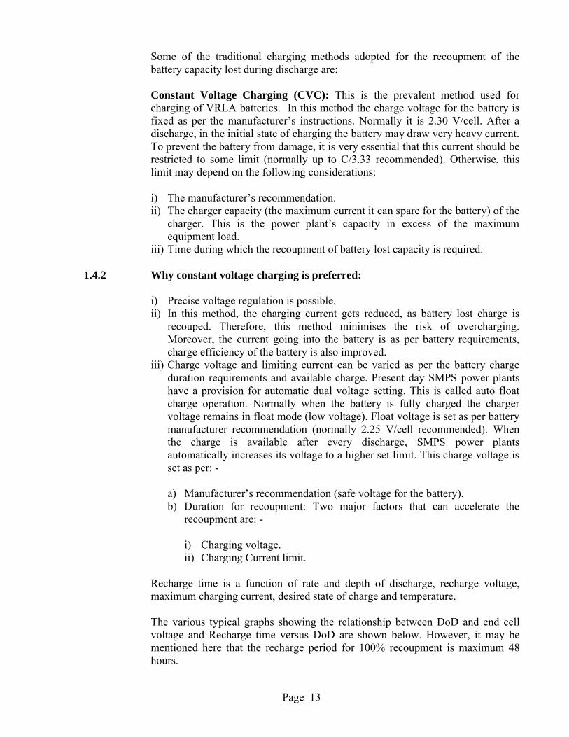
The various typical graphs showing the relationship between DoD and end cell voltage and Recharge time versus DoD are shown below. However, it may be mentioned here that the recharge period for 100% recoupment is maximum 48 hours.
Page 14
1.4.3 Graph showing DOD up-to 60% & End Cell Voltage @ C/10 Rate of Discharge Table:
Sl No.
Depth of Discharge
End Cell Voltage
(V)
1 10% DOD 2.072
2 20% DOD 2.064
3 30% DOD 2.054
4 40% DOD 2.043
5 50% DOD 2.022
6 60% DOD 2.006
Graph showing DOD up to 80% & End Cell Voltage @ C/10 Rate of Discharge Table:
Sl No.
Depth of Discharge
End Cell Voltage
(V)
1 10% DOD 2.072
2 20% DOD 2.064
3 30% DOD 2.054
4 40% DOD 2.043
5 50% DOD 2.022
6 60% DOD 2.006
7 70% DOD 1.987
8 80% DOD 1.966
1.4.4 Graph showing Recharge Time (Voltage 2.25V/cell and Current limited to 0.1C) Vs Various Depths of discharge.
DOD80% SOC
90% SOC
95% SOC
100% SOC
10% 0 0 2 3
20% 0 2 3 5
30% 2 4 6 8
40% 3 5 8 12
50% 5 8 12 16
60% 8 10 16 24
70% 10 12 20 32
80% 12 16 24 42
90% 16 20 30 55100% 20 24 36 72
1.960
1.980
2.000
2.020
2.040
2.060
2.080
10% DOD 20% DOD 30% DOD 40% DOD 50% DOD 60% DOD
Series1
1.900
1.950
2.000
2.050
2.100
10%DOD
20%DOD
30%DOD
40%DOD
50%DOD
60%DOD
70%DOD
80%DOD
En
d C
ell V
olta
ge (V
)
Depth of Discharge (%)
Graph b/w DOD Vs ECV @ C/10 Rate of Discharge
Page 15
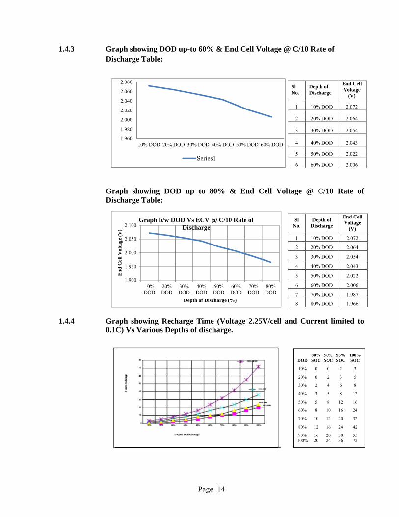
1.4.5 Graph showing Recharge Time (Voltage 2.25 V/cell and Current limited to 0.2C) Vs Various Depths of discharge
1.4.6 Graph showing Recharge Time (Voltage 2.3V/cell and Current limited to 0.1C) Vs Various Depths of discharge
1.4.7 Graph showing Recharge Time (Voltage 2.3V/cell and Current limited to 0.2C) Vs Various Depths of discharge
80% SOC
90% SOC
95% SOC
100% SOC
0
10
20
30
40
50
60
10% 20% 30% 40% 50% 60% 70% 80% 90% 100%
Ho
urs
rec
har
ge
Depth of discharge
DOD80% SOC
90% SOC
95% SOC
100% SOC
10% 0 0 1 2
20% 0 1 2 3
30% 1 2 3 5
40% 2 3 4.5 8
50% 3 5 6.5 11
60% 4.5 6.5 9 16
70% 6 8.5 12 22
80% 8 10.5 16 30
90% 10 13 20 40
100% 12 16 24 50
DOD80% SOC
90% SOC
95% SOC
100% SOC
10% 0 0 0.75 1.5
20% 0 0.75 1.5 2.25
30% 0.75 1.5 2.25 3.8
40% 1.5 2.25 3.4 6
50% 2.25 3.75 4.9 8.3
60% 3.5 4.9 6.8 12
70% 4.5 6.4 9 16.5
80% 6 8.1 11.5 22.5
90% 7.5 10 14.5 30
100% 9 12 18 37.5
DOD80% SOC
90% SOC
95% SOC
100% SOC
10% 0 0 1.5 2.3
20% 0 1.5 2.5 3.8
30% 1.3 3 4.1 6
40% 2.3 4 6 9
50% 3.8 5.9 8.5 12.5
60% 5.5 7.5 11 18
70% 7.1 9.3 14.5 24
80% 9 12 18 31.5
90% 12 15 22 41.3
100% 15 18 27 54
Page 16
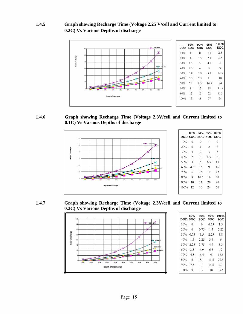
1.4.8 Graph showing Recharge Time (Voltage 2.35V/cell and Current limited to 0.2C) Vs Various Depths of discharge
1.4.9 Analysis of Graphs and Tables: On the analysis of the graphs and tables for various charging voltages and battery path current limits, it may be observed that by increasing the charging voltage or battery path current or both, the charging time is reduced. It has its own limitations and side effects: -
a) Charging voltage 2.30 V/cell or higher: In case of VRLA batteries 2.30 V/cell is considered as a gassing voltage. Excessive gassing may lead to early dry-out. Moreover, it will result in increase in the battery temperature, which is not desirable.
b) Charging at 2.30 V and Charging current 0.2C: The cells and battery has some limit to charge acceptance, which depends on the battery design. If higher current for long duration is permitted, it may result in rise in the cell temperature, which is not desirable. If at all required, it should only be used after temperature compensation circuitry is fully connected and functional. Moreover, this will require the additional FR-FC modules for the charging of the battery. For example, if at present 4 modules are required for the charging of the battery, we will require 8 FR-FC modules if battery path current is limited to 0.2C.
1.4.10 Battery Charging Solution for recoupment: The most ideal solution for fast recoupment may be: -
a) The Float & charge voltages should be set up to 2.25 V/cell & 2.30 V/cell respectively. This will also help in overcoming polarization of the +ve plate. Also ensure that these limits are not disturbed.
Note: These limits can be set, if the battery manufacturer recommends, under manual supervision only after the prier concurrence of the concerned Power Plant supplier.
DOD80% SOC
90%SOC
95%SOC
100%SOC
10% 0 0 0.5 1
20% 0 0.5 1 2
30% 0.5 1 2 3
40% 1 2 3 5
50% 2 3 4 7
60% 3 4 5 9
70% 4 6 7 12
80% 5 7 8 18
90% 6 8 10 20
100% 8 9 12 24
Page 17
b) The battery path current limit should be set as per the power plant capacity, i.e. available power plant rating minus the equipment load. But in no case it should be higher than C/3.33.
c) It should be ensured that the temperature compensation in power plant is fully functional.
d) Battery should not be allowed to remain under charged for longer period of times, because it will cause sulphation. Idea of mobile DG set for a group of stations may be explored to fully charge the battery periodically, in case the electric supply conditions is such that the battery cannot be recouped by AC mains.
e) Use only power plant compatible with VRLA batteries.
f) The battery should be sized properly so that the autonomy requirements are met with 80% of its rated capacity (50% in the cold regions).
1.5 Monitoring of VRLA Batteries:
1.5.1 No foolproof indicators/tools for knowing and predicting the health and life of the battery has been evolved/devised.
In the initial stages of its inception these batteries were called Maintenance Free Batteries. This terminology gave the impression to the users that these batteries are to be “installed and forgotten”. Due to this misconception, no proper attention was given to these batteries, which has led to failures of these batteries.
The commonly used parameters to keep the tab on the health and life of the Flooded type batteries such as observing the level of electrolyte measured of Specific Gravity (SG) cannot be applied to VRLA batteries as they are sealed batteries using starved electrolyte technology.
Since the VRLA batteries were introduced in the Department, the need for some device or method or technique was felt which could give some idea about the state of charge, expected life and expected residual life of the battery. Because it was essential for the service provider to keep himself informed about the state of health of battery and warn him well in advance about the impending failure of the battery for the provision of uninterrupted telecom services to its users.
1.5.2 A large number of techniques/methods have been explored and tried by various agencies in the field. Till date, not a single method/test instrument, capable of foolproof prediction about the impending failure of the battery has been evolved/devised. On the other hand, combining some of them, the state of health & expected residual life of the battery can be predicted more precisely & reliably. Some of the methods/techniques used for the prediction of the state of health & expected residual capacity of the battery are: -
Page 18
a) Periodic physical inspection of each cell of the battery for cracks & leakage etc.
b) Discharge of battery for a short duration say 30 minutes to 1 hour and recording the voltages of each cell in the string.
c) Measurement of a mark deviation (>30%) in the conductance of the cell as compared to the one recorded at the time of commissioning. These measurements should be taken OFF-line as detailed in clause 1.5.2.3.
d) Measurement & recording of cell temperature periodically.e) Float Voltage of cells & its comparison with the mid-point voltage.f) Float current in fully charged battery.g) Discharge at C/10 rate up to the voltage corresponding to 80 % DoD specified
by the manufacturer. Recommended frequency for this discharge test is once in a year for pure Float applications and once in 6 months for cyclic applications. Measure and record individual cell voltages at regular intervals and at the end of discharge.
h) There should not be any loose connection at the battery terminals.
1.5.2.1 Periodic Physical inspection: Each cell in the battery string should be inspected periodically for any damage, crack or leakage. An early detection may help in necessary remedial action to prevent failure of the cell/battery. It should also be ensured that sealing has not developed any type of deformity.
Recommendation: Physical inspection may preferably be carried out regularly and it should be ensured that the inspection is carried out at least every week.
1.5.2.2 Battery partial discharge test: This test is the most simple and un-expensive method to detect any sign of impending failure (not the expected residual life) of a cell in a string.
The test discharge tables supplied by the manufacturer with the battery should be kept at an easily accessible place as this table will be used as a reference.
Every partial test discharge should be properly recorded for future reference and comparison.
In this test, the battery is put to a test discharge by shutting down the power plant for short duration of 30 minutes, one hour or a duration as decided by the in-charge of the unit, so that 20% (approx.) of the battery is discharged.
This test should be conducted only on fully charged battery if it has not been put to load for some time.
The voltage of each cell should be recorded with a least count of 1 mV i.e. 0.001 V periodically during this test.
Any cell showing drift in voltage, in excess of 5%, as compared to the voltages of other cells in the battery, it should be put to further scrutiny.
Page 19
By comparing the discharge voltages with the initial voltages we may have some idea about the loss of capacity of the cell and battery.
Recommended Meter: Digital Volt meter should be capable to read with an accuracy of ± 0.5 % and least count of 1 mV.
1.5.2.3 Conductance Measurement: Though a large number of test instruments are available for measurement of conductance but most of them are with poor reliability & accuracy. More over these measurements are required to be carried in OFF Line (battery is isolated both from charger & load). In these cases, analog meters become more unreliable because of noise induced by Telecom equipment & power plant.
It is also true that there is little data available on the long term trends of cell conductance.
Different cells from different manufacturers & of different lots from the same manufacturers will have different conductance.
Normally difference in conductance in any cell should be less than 30% as compared to the other cells in the same battery bank. This indicates the healthy state of the cell in the battery bank. The difference in conductance of more than 40 % indicates the imminent failure of the cell in the battery bank.
In the range 30% to 40%, it is very critical & difficult to predict the state of cell in the battery bank because there is uncertainty of 5%in the measurement of the conductance and also the reference conductance is also known to be within 5%.
There are a large number of meters available in the market with or without computer interface.
The conductance value of each cell given in conductance table provided by the manufacturers should be verified at the time of commissioning and should be taken as the reference.
The readings may be taken at the time of partial test discharge preceded by full charge (i.e. at 100 % SoC) and scrutinized for deviations. In case deviations in any of the cell are observed outside the specified limits of 30%, it should be put to further investigation.
The readings taken during conductance measurement test of the cell should be recorded and supplied to the user for reference.
Recommended Meter: Digital conductance meter with online accuracy 2% and resolution of 3 places of decimal or least count of 1 Siemen. Its power drain from the cell/battery during test should not be more than 0.5A.
Page 20
1.5.2.4 Temperature of the cell/battery & life of the battery: Temperature at which the battery works is another important factor which affects the life of the battery seriously. The chemical reaction in the cell depends mainly on two factors the charging voltage and its temperature. Higher the temperature, faster is the reaction in the cell. It is also true that faster the reaction higher is the active material shedding, gassing and grid corrosion. The gassing may onset the thermal runaway.
It is also an important factor that the cell temperature and battery deterioration is not a linear but an Arrhenius relation (every 10-degree rise in temperature doubles the chemical reaction). In the light of this fact it is essential to effectively monitor and control the temperature of the cell/battery.
The SMPS power plants as per GR No. TEC/GR/FLA/SMP-001/06/JUN.2010 with amendments has taken care of the battery to some extent by slowing down the chemical reaction by reducing the charger voltage. But this has the following limitations:
i) It monitors the temperature of the pilot cell only. ii) It simply slows down the chemical reaction by pulling down the charger
voltage, without creating an alarm.iii) The temperature sensor may not give accurate readings.
It is important to measure the individual cells temperature periodically and keep a record for study and analysis for prediction of the residual life of the battery. Temperature sensors with computer interface should be available for the purpose.
Recommended Meter: Thermometers/temperature sensor/probes should be capable of reading in steps of 0.1° C and of accuracy of 0.1° C.
1.5.2.5 Float Voltage: Float voltage is another important parameter on which the life & performance of the battery depends. Though SMPS power plant as per TEC GR No. TEC/GR/FLA/SMP-001/06/JUN.2010 with amendments provide for temperature compensation of the battery, but the initial setting of the battery float voltage is very essential. The float voltage should be so set that the corresponding voltage at 27 degree Centigrade should be 2.25 V/cell for float voltage and 2.30 V/cell for charge voltage taking the adjustment factor 3 mV/Cell/° C.
Moreover, in case of parallel strings, the float current in each string will depend on the internal resistance of the string. Therefore, it is essential to ensure that the parallel strings are properly matched for conductance and resistance.
1.5.2.5.1 Float voltage Monitoring:
1.5.2.5.1.1 Mid-point Voltage Measurement: Some battery monitors measure the midpoint voltage of each battery string. This is very simple approach to detect voltage deviations within string. In this method monitor will create an alarm when there is a sufficient imbalance in the two half string voltage. This method has its own
Page 21
limitations because as the system voltage increases, the midpoint monitoring loses its resolution and as such also loses its ability to discern a deviant cell.
1.5.2.5.1.2 Individual cell Monitoring: To achieve the optimum benefit of voltage monitoring, it is essential that the voltage monitoring is done at cell level. In this technique the voltage of each cell is measured and deviation in any of the cell can be detected quickly and easily and remedial action required can be taken.
Though the power plants as per TEC GR No. TEC/GR/FLA/SMP-001/06/JUN 2010 with amendments, do have the provision for cell voltage monitoring but this facility has been incorporated recently in the power plants of some of the International manufacturers & may be implemented in the field.
Recommended Voltmeter: Digital Voltmeter should be capable to read three place decimal with accuracy 1 mV.
1.5.2.6 Current Measurements: Current for all the three states charge/discharge/float, of battery are important factors affecting and predicting the life and state of health of a battery or a battery in a parallel string.
The current drawn by a battery or a battery in the parallel string will depend on the internal resistance and conductance of a battery. The battery with lower internal resistance will draw more current and as such will lead to faster chemical reaction. In the light of this fact it is important that the batteries in a parallel string draw a current within a specified window/tolerance. It is also to be mentioned thata fully charged battery should not draw more than 400 mA per 1000 AH at 27 degrees centigrade, when it is on float, any mark deviation from this value need investigation. A large number of current measuring devices are available. Proper attention should be given to the requirements while selecting such instruments.
Recommended Meter: Digital meter should be capable to read three place decimal with accuracy 1 mA.
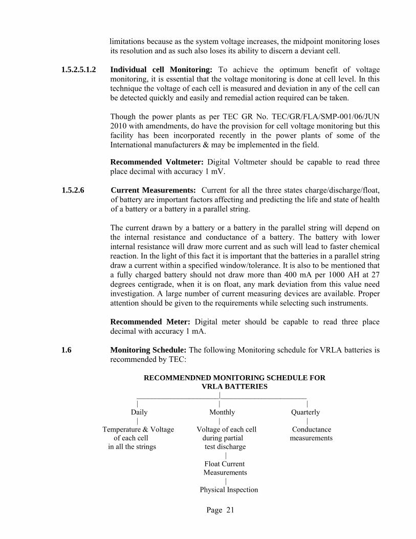
1.6 Monitoring Schedule: The following Monitoring schedule for VRLA batteries is recommended by TEC:
RECOMMENDNED MONITORING SCHEDULE FORVRLA BATTERIES
______________________|_______________________ | | |
Daily Monthly Quarterly | | |
Temperature & Voltage Voltage of each cell Conductance of each cell during partial measurements
in all the strings test discharge |
Float Current Measurements
|Physical Inspection
Page 22
Note: The Batteries can be monitored, for the parameters, as per the procedure given in the respective clauses of this document.
END OF THE CHAPTER 1

Page 23
Page 24
CHAPTER 2
PLANNING GUIDELINES OF VRLA BATTERIES
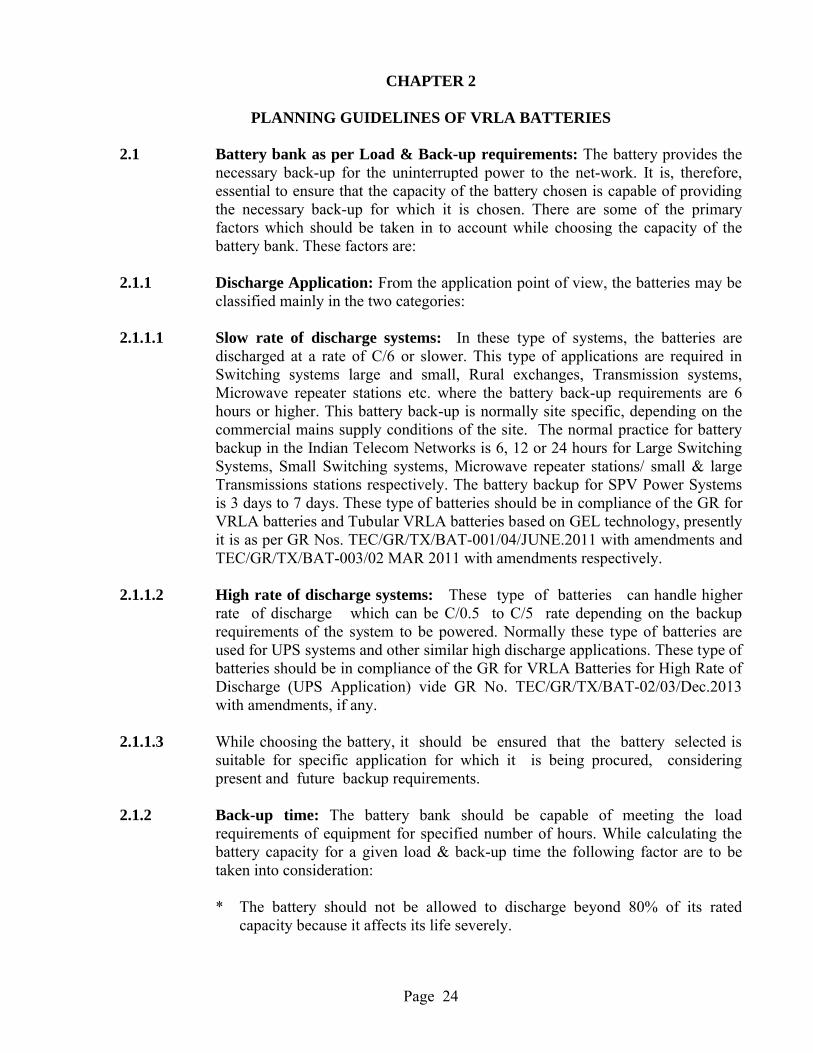
2.1 Battery bank as per Load & Back-up requirements: The battery provides the necessary back-up for the uninterrupted power to the net-work. It is, therefore, essential to ensure that the capacity of the battery chosen is capable of providing the necessary back-up for which it is chosen. There are some of the primary factors which should be taken in to account while choosing the capacity of the battery bank. These factors are:
2.1.1 Discharge Application: From the application point of view, the batteries may be classified mainly in the two categories:
2.1.1.1 Slow rate of discharge systems: In these type of systems, the batteries are discharged at a rate of C/6 or slower. This type of applications are required in Switching systems large and small, Rural exchanges, Transmission systems, Microwave repeater stations etc. where the battery back-up requirements are 6 hours or higher. This battery back-up is normally site specific, depending on the commercial mains supply conditions of the site. The normal practice for battery backup in the Indian Telecom Networks is 6, 12 or 24 hours for Large Switching Systems, Small Switching systems, Microwave repeater stations/ small & large Transmissions stations respectively. The battery backup for SPV Power Systems is 3 days to 7 days. These type of batteries should be in compliance of the GR for VRLA batteries and Tubular VRLA batteries based on GEL technology, presently it is as per GR Nos. TEC/GR/TX/BAT-001/04/JUNE.2011 with amendments and TEC/GR/TX/BAT-003/02 MAR 2011 with amendments respectively.
2.1.1.2 High rate of discharge systems: These type of batteries can handle higher rate of discharge which can be C/0.5 to C/5 rate depending on the backup requirements of the system to be powered. Normally these type of batteries are used for UPS systems and other similar high discharge applications. These type of batteries should be in compliance of the GR for VRLA Batteries for High Rate of Discharge (UPS Application) vide GR No. TEC/GR/TX/BAT-02/03/Dec.2013 with amendments, if any.
2.1.1.3 While choosing the battery, it should be ensured that the battery selected is suitable for specific application for which it is being procured, considering present and future backup requirements.
2.1.2 Back-up time: The battery bank should be capable of meeting the load requirements of equipment for specified number of hours. While calculating the battery capacity for a given load & back-up time the following factor are to be taken into consideration:
* The battery should not be allowed to discharge beyond 80% of its rated capacity because it affects its life severely.
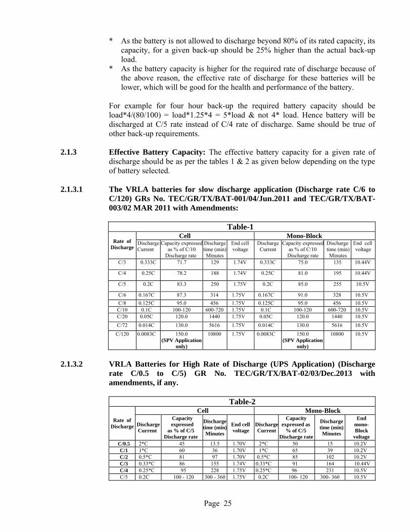
Page 25
* As the battery is not allowed to discharge beyond 80% of its rated capacity, its capacity, for a given back-up should be 25% higher than the actual back-up load.
* As the battery capacity is higher for the required rate of discharge because of the above reason, the effective rate of discharge for these batteries will be lower, which will be good for the health and performance of the battery.
For example for four hour back-up the required battery capacity should be load*4/(80/100) = load*1.25*4 = 5*load & not 4* load. Hence battery will be discharged at C/5 rate instead of C/4 rate of discharge. Same should be true of other back-up requirements.
2.1.3 Effective Battery Capacity: The effective battery capacity for a given rate of discharge should be as per the tables 1 & 2 as given below depending on the type of battery selected.
2.1.3.1 The VRLA batteries for slow discharge application (Discharge rate C/6 toC/120) GRs No. TEC/GR/TX/BAT-001/04/Jun.2011 and TEC/GR/TX/BAT-003/02 MAR 2011 with Amendments:
Table-1
Rate of Discharge
Cell Mono-BlockDischargeCurrent
Capacity expressed as % of C/10
Discharge rate
Dischargetime (min)Minutes
End cell voltage
Discharge Current
Capacity expressed as % of C/10
Discharge rate
Dischargetime (min)Minutes
End cell voltage
C/3 0.333C 71.7 129 1.74V 0.333C 75.0 135 10.44V
C/4 0.25C 78.2 188 1.74V 0.25C 81.0 195 10.44V
C/5 0.2C 83.3 250 1.75V 0.2C 85.0 255 10.5V
C/6 0.167C 87.3 314 1.75V 0.167C 91.0 328 10.5V
C/8 0.125C 95.0 456 1.75V 0.125C 95.0 456 10.5VC/10 0.1C 100-120 600-720 1.75V 0.1C 100-120 600-720 10.5VC/20 0.05C 120.0 1440 1.75V 0.05C 120.0 1440 10.5V
C/72 0.014C 130.0 5616 1.75V 0.014C 130.0 5616 10.5V
C/120 0.0083C 150.0(SPV Application
only)
10800 1.75V 0.0083C 150.0(SPV Application
only)
10800 10.5V
2.1.3.2 VRLA Batteries for High Rate of Discharge (UPS Application) (Discharge rate C/0.5 to C/5) GR No. TEC/GR/TX/BAT-02/03/Dec.2013 with amendments, if any.
Table-2
Rate of Discharge
Cell Mono-Block
DischargeCurrent
Capacityexpressed
as % of C/5Discharge rate
Dischargetime (min)Minutes
End cell voltage
Discharge Current
Capacity expressed as
% of C/5Discharge rate
Dischargetime (min)Minutes
Endmono-Block
voltageC/0.5 2*C 45 13.5 1.70V 2*C 50 15 10.2VC/1 1*C 60 36 1.70V 1*C 65 39 10.2VC/2 0.5*C 81 97 1.70V 0.5*C 85 102 10.2VC/3 0.33*C 86 155 1.74V 0.33*C 91 164 10.44VC/4 0.25*C 95 228 1.75V 0.25*C 96 231 10.5VC/5 0.2C 100 - 120 300 - 360 1.75V 0.2C 100- 120 300- 360 10.5V
Page 26
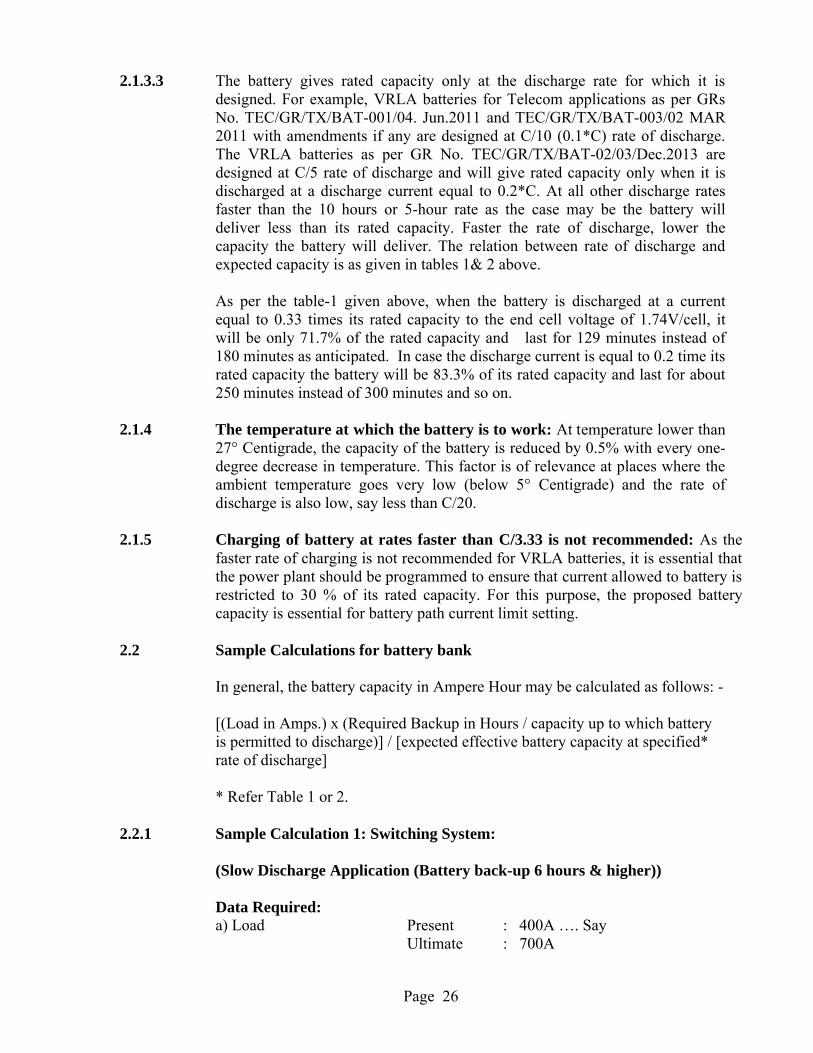
2.1.3.3 The battery gives rated capacity only at the discharge rate for which it is designed. For example, VRLA batteries for Telecom applications as per GRs No. TEC/GR/TX/BAT-001/04. Jun.2011 and TEC/GR/TX/BAT-003/02 MAR 2011 with amendments if any are designed at C/10 (0.1*C) rate of discharge. The VRLA batteries as per GR No. TEC/GR/TX/BAT-02/03/Dec.2013 are designed at C/5 rate of discharge and will give rated capacity only when it is discharged at a discharge current equal to 0.2*C. At all other discharge rates faster than the 10 hours or 5-hour rate as the case may be the battery will deliver less than its rated capacity. Faster the rate of discharge, lower the capacity the battery will deliver. The relation between rate of discharge and expected capacity is as given in tables 1& 2 above.
As per the table-1 given above, when the battery is discharged at a current equal to 0.33 times its rated capacity to the end cell voltage of 1.74V/cell, it will be only 71.7% of the rated capacity and last for 129 minutes instead of 180 minutes as anticipated. In case the discharge current is equal to 0.2 time its rated capacity the battery will be 83.3% of its rated capacity and last for about 250 minutes instead of 300 minutes and so on.
2.1.4 The temperature at which the battery is to work: At temperature lower than 27° Centigrade, the capacity of the battery is reduced by 0.5% with every one-degree decrease in temperature. This factor is of relevance at places where the ambient temperature goes very low (below 5° Centigrade) and the rate ofdischarge is also low, say less than C/20.
2.1.5 Charging of battery at rates faster than C/3.33 is not recommended: As the faster rate of charging is not recommended for VRLA batteries, it is essential that the power plant should be programmed to ensure that current allowed to battery is restricted to 30 % of its rated capacity. For this purpose, the proposed battery capacity is essential for battery path current limit setting.
2.2 Sample Calculations for battery bank
In general, the battery capacity in Ampere Hour may be calculated as follows: -
[(Load in Amps.) x (Required Backup in Hours / capacity up to which battery is permitted to discharge)] / [expected effective battery capacity at specified* rate of discharge]
* Refer Table 1 or 2.
2.2.1 Sample Calculation 1: Switching System:
(Slow Discharge Application (Battery back-up 6 hours & higher))
Data Required:a) Load Present : 400A …. Say
Ultimate : 700A
Page 27
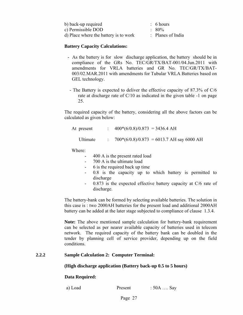
b) back-up required : 6 hours c) Permissible DOD : 80%d) Place where the battery is to work : Planes of India
Battery Capacity Calculations:
- As the battery is for slow discharge application, the battery should be in compliance of the GRs No. TEC/GR/TX/BAT-001/04.Jun.2011 with amendments for VRLA batteries and GR No. TEC/GR/TX/BAT-003/02.MAR.2011 with amendments for Tubular VRLA Batteries based on GEL technology.
- The Battery is expected to deliver the effective capacity of 87.3% of C/6 rate at discharge rate of C/10 as indicated in the given table -1 on page 25.
The required capacity of the battery, considering all the above factors can be calculated as given below:
At present : 400*(6/0.8)/0.873 = 3436.4 AH
Ultimate : 700*(6/0.8)/0.873 = 6013.7 AH say 6000 AH
Where:- 400 A is the present rated load- 700 A is the ultimate load- 6 is the required back up time- 0.8 is the capacity up to which battery is permitted to
discharge- 0.873 is the expected effective battery capacity at C/6 rate of
discharge.
The battery-bank can be formed by selecting available batteries. The solution in this case is : two 2000AH batteries for the present load and additional 2000AH battery can be added at the later stage subjected to compliance of clause 1.3.4.
Note: The above mentioned sample calculation for battery-bank requirement can be selected as per nearer available capacity of batteries used in telecomnetwork. The required capacity of the battery bank can be doubled in the tender by planning cell of service provider, depending up on the field conditions.
2.2.2 Sample Calculation 2: Computer Terminal:
(High discharge application (Battery back-up 0.5 to 5 hours)
Data Required:
a) Load Present : 50A …. Say
Page 28
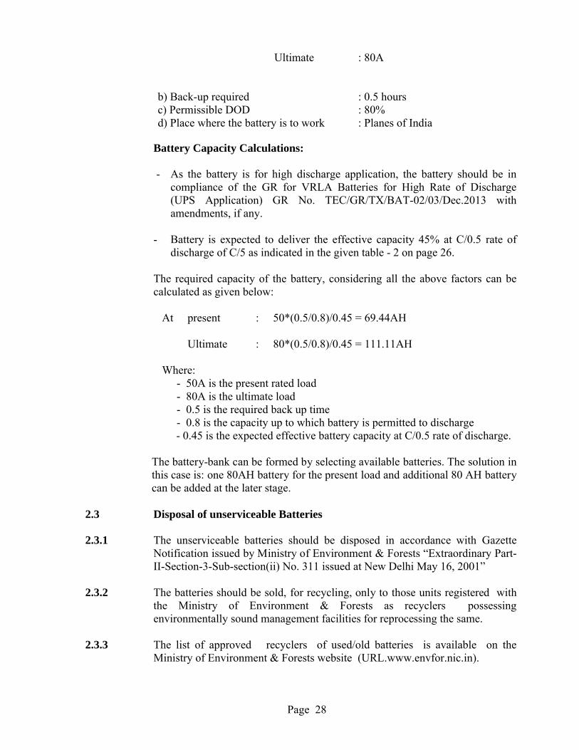
Ultimate : 80A
b) Back-up required : 0.5 hoursc) Permissible DOD : 80%d) Place where the battery is to work : Planes of India
Battery Capacity Calculations:
- As the battery is for high discharge application, the battery should be in compliance of the GR for VRLA Batteries for High Rate of Discharge (UPS Application) GR No. TEC/GR/TX/BAT-02/03/Dec.2013 with amendments, if any.
- Battery is expected to deliver the effective capacity 45% at C/0.5 rate of discharge of C/5 as indicated in the given table - 2 on page 26.
The required capacity of the battery, considering all the above factors can be calculated as given below:
At present : 50*(0.5/0.8)/0.45 = 69.44AH
Ultimate : 80*(0.5/0.8)/0.45 = 111.11AH
Where:- 50A is the present rated load- 80A is the ultimate load- 0.5 is the required back up time- 0.8 is the capacity up to which battery is permitted to discharge- 0.45 is the expected effective battery capacity at C/0.5 rate of discharge.
The battery-bank can be formed by selecting available batteries. The solution in this case is: one 80AH battery for the present load and additional 80 AH battery can be added at the later stage.
2.3 Disposal of unserviceable Batteries
2.3.1 The unserviceable batteries should be disposed in accordance with Gazette Notification issued by Ministry of Environment & Forests “Extraordinary Part-II-Section-3-Sub-section(ii) No. 311 issued at New Delhi May 16, 2001”
2.3.2 The batteries should be sold, for recycling, only to those units registered with the Ministry of Environment & Forests as recyclers possessing environmentally sound management facilities for reprocessing the same.
2.3.3 The list of approved recyclers of used/old batteries is available on the Ministry of Environment & Forests website (URL.www.envfor.nic.in).

Page 29
END OF THE CHAPTER 2

Page 30
Page 31
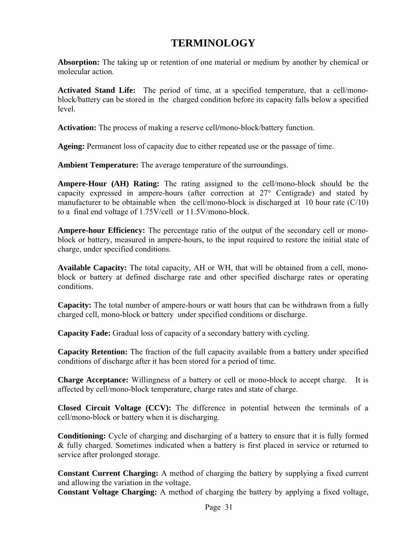
TERMINOLOGY
Absorption: The taking up or retention of one material or medium by another by chemical or molecular action.
Activated Stand Life: The period of time, at a specified temperature, that a cell/mono-block/battery can be stored in the charged condition before its capacity falls below a specified level.
Activation: The process of making a reserve cell/mono-block/battery function.
Ageing: Permanent loss of capacity due to either repeated use or the passage of time.
Ambient Temperature: The average temperature of the surroundings.
Ampere-Hour (AH) Rating: The rating assigned to the cell/mono-block should be the capacity expressed in ampere-hours (after correction at 27° Centigrade) and stated by manufacturer to be obtainable when the cell/mono-block is discharged at 10 hour rate (C/10)to a final end voltage of 1.75V/cell or 11.5V/mono-block.
Ampere-hour Efficiency: The percentage ratio of the output of the secondary cell or mono-block or battery, measured in ampere-hours, to the input required to restore the initial state of charge, under specified conditions.
Available Capacity: The total capacity, AH or WH, that will be obtained from a cell, mono-block or battery at defined discharge rate and other specified discharge rates or operating conditions.
Capacity: The total number of ampere-hours or watt hours that can be withdrawn from a fully charged cell, mono-block or battery under specified conditions or discharge.
Capacity Fade: Gradual loss of capacity of a secondary battery with cycling.
Capacity Retention: The fraction of the full capacity available from a battery under specified conditions of discharge after it has been stored for a period of time.
Charge Acceptance: Willingness of a battery or cell or mono-block to accept charge. It is affected by cell/mono-block temperature, charge rates and state of charge.
Closed Circuit Voltage (CCV): The difference in potential between the terminals of a cell/mono-block or battery when it is discharging.
Conditioning: Cycle of charging and discharging of a battery to ensure that it is fully formed & fully charged. Sometimes indicated when a battery is first placed in service or returned to service after prolonged storage.
Constant Current Charging: A method of charging the battery by supplying a fixed current and allowing the variation in the voltage.Constant Voltage Charging: A method of charging the battery by applying a fixed voltage,
Page 32
and allowing variations in the current. Also called constant potential charge.
Continuous Test: A test in which a cell/mono-block or battery is discharged to a prescribed end-point voltage without interruption.
Counter Electromotive Force: A voltage opposing the applied voltage. Also referred to as Back EMF.
Current Density: The current per unit active area of the surface of an electrode.
Cut-off Voltage: The cell/mono-block or battery voltage at which the discharge is terminated. It is also called end voltage.
Cycle: The discharge and subsequent or preceding charge of a secondary battery such that it is restored to its original conditions.
Cycle Life: The number of cycles under specified conditions which are available from a secondary battery before it fails to meet specified criteria of performance.
Cyclic application: Application in which cells/mono-block batteries are subjected to charge and discharge cycles on regular basis. In these type of applications, the batteries are subjected to short term charging.
Deep Discharge: Withdrawal of at least 80% of the rated capacity of a cell, mono-block or battery.
Depth of Discharge (DOD): The ratio of the quantity of electricity (usually in ampere-hours) removed from a cell or battery on discharge to its rated capacity.
Efficiency: The ratio of the output of a secondary cell or battery to the input required to restore it to the initial state of charge under specified conditions.
Electrolyte: The medium which provides the ion transport mechanism between the positive and negative electrodes of a cell/mono-block.
End Voltage: The prescribed voltage at which the discharge (or charge, if end-of-charge voltage) of a cell/mono-block or battery may be considered complete (also cut off voltage).
Energy Density: The ratio of the energy available from a cell/mono-block or battery to its volume (WH/L–Volumetric energy density). Also used on a weight basis (WH/Kg–Gravimetric energy density).
Fast Charge: A rate of charging which returns full capacity to a rechargeable battery, usually within an hour.
Float application: Application in which cells/mono-block batteries are subjected to be on constant charge with occasional discharge. In these type of applications, the batteries are subjected to long term charging at a lower charge voltage limit. Float Charge: A method of maintaining a cell/mono-block or battery in a charged condition by
Page 33
continuous, long-term constant-voltage charging, at a level sufficient to balance self-discharge.
Gas Recombination: Method of suppressing hydrogen generation by recombining it with oxygen on the negative electrode, as the cell approaches full charge.
Half-Cell: An electrode (either the anode or cathode) immersed in a suitable electrolyte.
Hourly Rate: A discharge rate, in amperes, of a cell/mono-block or battery which will deliver the specified hours of service to a given end voltage.
Internal Resistance: The opposition or resistance to the flow of an electric current within a cell or battery. It is the sum of the ionic and electronic resistances of the cell/mono-block components.
Life: For rechargeable batteries, the duration of satisfactory performance, measured in years float life) or in the number of charge/discharge cycles (cycle life).
Load: The term used to indicate the current drawn from the battery.
Lot: All batteries of the same type, design and rating, manufactured by the same factory during the same period, using the same process and material, offered for inspection at a time should constitute a lot.
Maintenance-Free Battery: A secondary battery which does not require periodic "topping up" to maintain electrolyte volume.
Open-Circuit Voltage (OCV): Open-circuit voltage is the difference of electrical potential between two terminals of a battery when disconnected from the circuit and there is no external load connected.
Overcharge: The forcing of current through a cell/mono-block after all the active material has been converted to the charged state. In other words, continued charging even after 100% state of charge is achieved.
Over discharge: Discharge below the point where the full capacity of the cell/mono-block has been obtained.
Over voltage: The potential difference between the equilibrium potential of an electrode and that of the electrode under an imposed polarisation current.
Oxygen Recombination: The process by which oxygen generated at the positive plate during charge reacts with the pure lead material of the negative plate and in the presence of sulfuric acid and reforms water.
Parallel: Term used to describe the interconnection of cells or batteries in which all of the like terminals are connected together. Parallel connections increase the capacity of the resultant battery as follows: -
Cp = n X Cu
Page 34
Where Cp is the resultant capacity, n is the number of cells or batteries connected in parallel & Cu is capacity of the each cell or battery.
Rated Capacity: The number of ampere-hours a cell/mono-block or battery can deliver under specific conditions (rate of discharge, end voltage, temperature): usually the manufacturer's rating.
Recombination: A term used in a sealed cell construction for the process whereby internalpressure is relieved by reaction of oxygen with the negative active material.
Reference Electrode: A specially chosen electrode which has a reproducible potential against which other electrode potentials may be referred.
Self-Discharge: The loss of useful capacity of a cell/mono-block or battery due to internal chemical action (local action).
Semi-Permeable Membrane: A porous film that will pass selected ions.
Separator: An ion permeable, electronically non-conductive, spacer or material which prevents electronic contact between electrodes of opposite polarity in the same cell.
Series: The interconnection of cells/mono-blocks or batteries in such a manner that the positive terminal of the first is connected to the negative terminal of the second, & so on. Series connections increase the voltage of the resultant battery as follows: -
Vs = n X Vu
Where Vs is the resultant voltage, n is the number of cells/mono-blocks or batteries connected in series & Vu is voltage of each cell/mono-block or battery.
Service Life: The period of useful life of a cell/mono-block or battery before a predetermined end-point voltage is reached.
Shelf Life: The duration of storage under specified conditions at the end of which a cell/mono-block or battery still retains the ability to give the specified performance.
Short Circuit Current: The initial value of the current obtained from a cell/mono-block orbattery in a circuit of negligible resistance.
Specific Gravity: The specific gravity of a solution is the ratio of the weight of the solution to the weight of an equal volume of water at a specified temperature.
Standby Battery: A battery designed for emergency use in the event of a main power failure.
Starved Electrolyte Cell: A cell containing little or no free fluid electrolyte. This enables gases to reach electrode surfaces during charging and facilitates gas recombination.
State-of-Charge (SOC): The available capacity in a cell/mono-block or battery expressed as a
Page 35
percentage of rated capacity.
Sulphation: Process occurring in lead batteries that have been stored & allowed to self-discharge for extended periods of time. Large crystals of lead sulphate grow and interfere with function of the active materials.
Thermal Runaway: A condition whereby a cell/mono-block or battery on charge or discharge will overheat and destroy itself through internal heat generation caused by high overcharge or over discharging current or other abusive condition.
Trickle Charge: A charge at a low rate, balancing losses through a local action and/or periodic discharge, to maintain a cell/mono-block or battery in a fully charged condition.
Vent: A normally sealed mechanism which allows for the controlled escape of gases from within a cell/mono-block.
Vented Cell/mono-block: A cell/mono-block design incorporating a vent mechanism to relieve excessive pressure and expel gases that are generated during the operation of the cell/mono-block.
Voltage Delay: Time delay for a cell/mono-block or battery to deliver the required operating voltage after it is placed under load.
Voltage Efficiency: The ratio of average voltage during discharge to average voltage during recharge under specified conditions of charge and discharge.
Watt Hour (WH) Capacity: The quantity of electrical energy measured in watt hours which may be delivered by a cell/mono-block or battery under specified conditions.
Watt Hour (WH) Efficiency: The ratio of the watt hours delivered on discharge of a battery to the watt hours needed to restore it to its original state under specified conditions of charge and discharge. The percentage WH efficiency is the product of AH efficiency & the ratio of average discharge and recharge voltage.
Wet Shelf Life: The period of time that a cell/mono-block or battery can stand in the charged or activated condition before deteriorating below a specified capacity.
Working Voltage: The typical voltage or range of voltage of a cell/mono-block or battery during discharge.
Page 36
ABBREVIATIONS
A or Amps AmperesAC Alternate CurrentAH Ampere HourAGM BIS
Absorbed Glass MattBureau Of Indian Standards
BSNL Bharat Sanchar Nigam LimitedCACT Component Approval Centre of TelecommunicationdB DecibeldBA Decibel AbsoluteDC Direct Current° C Degrees CentigradeDG Diesel GeneratorEmf Electro motive forceFSD Full Scale DeflectionGR Generic RequirementsHz HertzIS Indian Standards
Kg Kilo GramsLED Light Emitting DiodesLCD Liquid Crystal DevicemA mili AmperesMOV Metal Oxide VaristorMTBF Mean Time between FailuresMTNL Mahanagar Telephone Nigam Limitedms Mili secondsmV Mili VoltsPF Power factorQA Quality AssuranceQM Quality ManualSMPS Switch Mode Power SupplyT & D Technical & DevelopmentV VoltsVRLA Valve Regulated Lead AcidWH Watt Hour
-- END OF THE DOCUMENT --