Embed Size (px)
Citation preview

present Navy program, advancedchevrons (see Figure 3) are beinginstalled on F/A-18E/F Super Hornetnozzles9 and new corrugation designsare being developed and tested.However, additional significantadvances in reducing noise from high-performance aircraft require betterunderstanding and quantification of thejet noise problem – both source andhuman impact. With this goal in mind,research offices (Office of NavalResearch (ONR), Air Force ResearchLaboratory (AFRL), Strategic Researchand Development Program, etc.) aresponsoring programs aimed at charac-terizing the physics of military jet noisegeneration and propagation. This articledescribes characteristics of supersonicjet noise as observed from recent analy-ses of extensive military jet aircraftmeasurements by the authors. Also
described are concurrent efforts by other investigators undera jet noise reduction10 program sponsored by ONR andNASA.
Supersonic Jet Noise: An OverviewThe turbulence generated in supersonic, high-speed jet
flows is responsible for the dominant noise associated withhigh-performance military engines. Supersonic jet noise canhave multiple components, referred to as mixing noise,screech, and broadband shock-associated noise. Tam11 andMorris and Lilley12 provide reviews of these noise phenome-na for the interested reader. Because mixing noise in the aftregion dominates the overall noise radiation, its characteris-tics are emphasized in this article.
The acoustic radiation associated with mixing noisefrom a jet is understood to originate both from unsteadyfluctuations from small-scale eddies and from coherentinteraction between larger-scale turbulent features.13-15 Thislarge-scale turbulence is comprised of varying lengths,amplitudes, and convection speeds, with an associatedwavenumber spectrum. Some combinations of wavenumbersand axial velocities will result in a sonic disturbance and sub-sequent radiation to the far field. Other local pressure distur-
Introduction
In 1932, the applied mathematicianHorace Lamb, a notable contributorto the field of acoustics, addressed
the British Association for theAdvancement of Science. He reported-ly quipped, “I am an old man now, andwhen I die and go to heaven there aretwo matters on which I hope forenlightenment. One is quantum elec-trodynamics, and the other is the tur-bulent motion of fluids. And about theformer I am rather optimistic.” Morerecently, Richard Feynman dubbed tur-bulence “the most important unsolvedproblem in classical physics.”1 Betweenthe difficulties in characterizing itssource and understanding the transi-tion from mean fluid flow to wavemotion, the noise radiated from turbu-lent jets is a topic that remains illunderstood. Numerous research stud-ies, beginning with the seminal works of Sir James Lighthillin the 1950’s,2,3 have probed the origins or properties of jetnoise. For example, a Google Scholar® search for publica-tions containing the exact phrase “jet noise,” yielded 678results for the year 2012 alone.
Although greater reductions are still required, significantprogress has been made to reduce commercial aircraft enginenoise through the introduction of regulations4 and techno-logical advancements, including the development of highbypass flow ratio engines with chevrons. However, the lowbypass turbofan engines that propel today’s high-perform-ance tactical aircraft also produce “the sound of freedom” –noise levels sufficient to cause concern regarding personnelhearing loss on airfields and aircraft carriers (see Figure 1 fortypical maintainer positions) and increased annoyance forcommunities near bases. Figure 2, which shows compensa-tion, through 2005, to U.S. military veterans whose primarydisability is hearing loss, indicates an alarming trend in hear-ing impairment. Though not all military hearing loss can beattributed to jet noise, noise reduction strategies designed toalter the turbulent flow, including various means of injectingfluid at the nozzle exit,5 advanced chevrons6 and corruga-tions,7,8 have been proactively explored for many years. In a
8 Acoustics Today, July 2013
THE “SOUND OF FREEDOM”: CHARACTERIZING JET NOISE FROM HIGH-PERFORMANCE
MILITARY AIRCRAFTKent L. Gee, Tracianne B. Neilsen, and Alan T. Wall
Department of Physics and AstronomyBrigham Young University
Provo, UT 84602
J. Micah Downing and Michael M. JamesBlue Ridge Research and Consulting, LLC
Asheville, NC 28801
“[T]urbofan engines that
propel today’s high-
performance tactical aircraft
also produce “the sound of
freedom” – noise levels
sufficient to cause concern
regarding personnel hearing
loss on airfields and aircraft
carriers and increased
annoyance for communities
near bases.”
v9i3_pfinal_rev3_ECHOES fall 04 final 8/27/13 2:21 PM Page 8

Jet Noise from Military Aircraft 9
Fig. 1. Military jet catapult launch in the USS Theodore Roosevelt. Courtesy of the U.S. Office of Naval Research.
Fig. 2. U.S. Veterans disability benefits for hearing loss as primary disability. Total cost to Department of Defense, in millions of dollars for the years 1977-2005. Data fromRef. 11.
v9i3_pfinal_rev3_ECHOES fall 04 final 8/27/13 2:21 PM Page 9
10 Acoustics Today, July 2013
bances in the linear hydrodynamic (i.e. acoustic) near fielddecay exponentially, or evanesce, in the radial direction.When the mean convective jet velocity is supersonic withrespect to the ambient medium, the radiation efficiency isenhanced by Mach wave radiation. The Mach waves’ direc-tionality is determined by trace velocity matching of themean convection speed of the turbulence near the shear layerwith the sound speed outside. Readers familiar with struc-tural acoustics will ientify parallels between jet noise radia-tion mechanisms and subsonic and supersonic wave motionin plates.16
Because of the dominance of the Mach wave radiation,the overall noise from supersonic jets is directional, with themaximum levels often occurring 30-60° relative to the down-stream jet axis. This principal lobe in overall sound pressurelevel (OASPL) shifts upstream with increasing jet velocityand broadens with increases in temperature.12 In terms of themixing noise spectrum, the peak frequency and the shapechange as a function of angle. The characteristic Strouhalnumber, (St=fD/uj, where f is frequency, D is nozzle diameter,and uj is jet velocity) changes from ~0.1-0.3 in the peak radi-ation direction to higher values toward the sideline (90°) and
the spectral shape evolves from a relatively peaked “haystack”spectrum near the maximum radiation angles to a rounderspectral shape toward and upstream of the sideline.
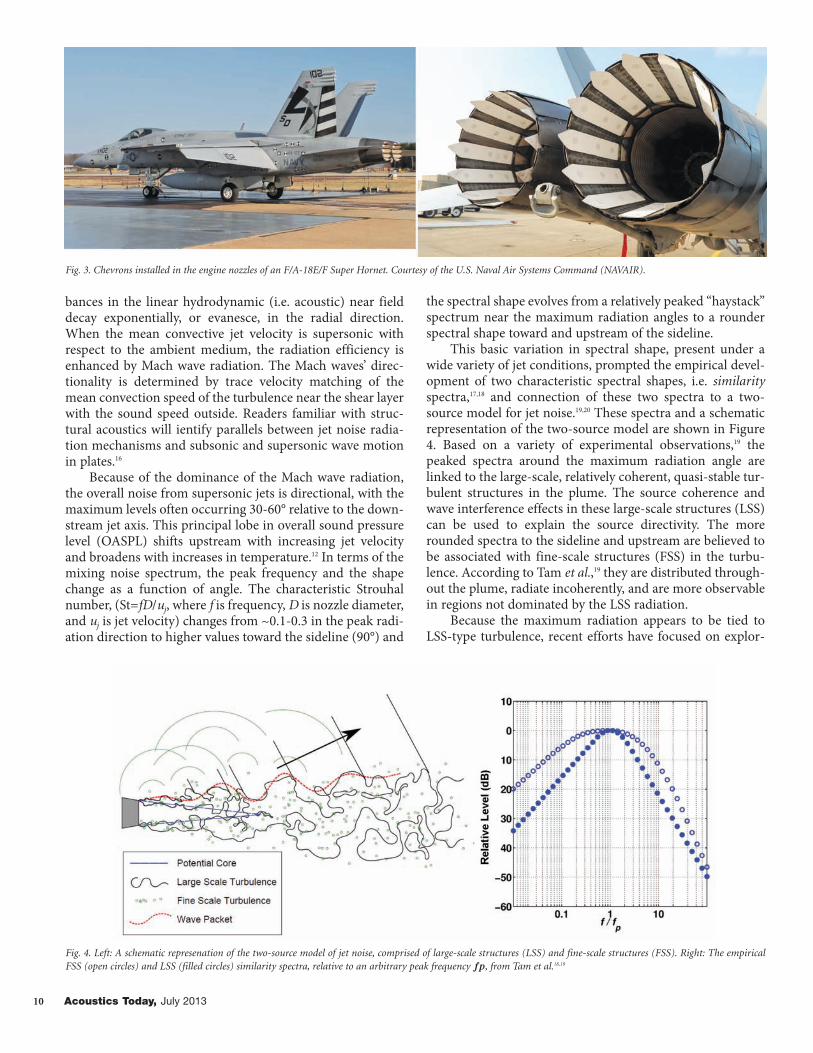
This basic variation in spectral shape, present under awide variety of jet conditions, prompted the empirical devel-opment of two characteristic spectral shapes, i.e. similarityspectra,17,18 and connection of these two spectra to a two-source model for jet noise.19,20 These spectra and a schematicrepresentation of the two-source model are shown in Figure4. Based on a variety of experimental observations,19 thepeaked spectra around the maximum radiation angle arelinked to the large-scale, relatively coherent, quasi-stable tur-bulent structures in the plume. The source coherence andwave interference effects in these large-scale structures (LSS)can be used to explain the source directivity. The morerounded spectra to the sideline and upstream are believed tobe associated with fine-scale structures (FSS) in the turbu-lence. According to Tam et al.,19 they are distributed through-out the plume, radiate incoherently, and are more observablein regions not dominated by the LSS radiation.
Because the maximum radiation appears to be tied toLSS-type turbulence, recent efforts have focused on explor-
Fig. 3. Chevrons installed in the engine nozzles of an F/A-18E/F Super Hornet. Courtesy of the U.S. Naval Air Systems Command (NAVAIR).
Fig. 4. Left: A schematic represenation of the two-source model of jet noise, comprised of large-scale structures (LSS) and fine-scale structures (FSS). Right: The empiricalFSS (open circles) and LSS (filled circles) similarity spectra, relative to an arbitrary peak frequency 𝒇𝒑, from Tam et al.18,19
v9i3_pfinal_rev3_ECHOES fall 04 final 8/27/13 2:21 PM Page 10

Jet Noise from Military Aircraft 11
ing its properties. Azimuthal modal decompositions21,22 ofnumerical and experimental data have revealed relativelyaxisymmetric radiation at low frequencies, with the signifi-cance of higher-order helical modes increasing as a functionof frequency and toward the sideline direction. These modescan be described in terms of wave packets, wave-like func-tions that mimic the growth and decay of turbulence insta-bilities with downstream distance (see Figure 4), and whosecoherence extends over multiple characteristic wavelengths.Jordan and Colonius23 have recently reviewed the use of wavepackets to characterize LSS radiation from jets; wave packets’tie to jet noise reduction efforts are described near the con-clusion of this article.
A characteristic of high-power military jet noise that isparticularly important to human perception is the presenceof acoustic shocks that produce a highly audible irregularpopping sound in the waveform. Historically, FfowcsWilliams et al.24 described jet “crackle” as being due to sharpshock-like compressive features in the waveform. Althoughthey believed the shocks were radiated from the jet directly,shocks may also form and steepen as high-amplitude noisepropagates nonlinearly. Nonlinear acoustic wave propaga-tion25,26 in air results when the source characteristics (ampli-tude, frequency, spatial extent) are such that an amplitude-dependent sound speed occurs, resulting in an alteration ofwaveform shape and possible shock formation. Recent stud-ies27-29 on the nonlinear propagation on noise from militaryjets have shown that the evolution of these shocks has a sig-nificant impact on the high-frequency portion of the spec-trum. Nonlinear effects in jet noise have also been observedin supersonic laboratory30,31 scale jets.
As an example28 of acoustic shocks in jet noise propaga-tion, Figure 5 displays measured waveforms from a static,afterburning F-22A Raptor at locations between 23 and 305m along the maximum radiation angle 55° from the down-stream jet axis. Highlighted is the steepening of acousticshocks around 3.21 and 3.23 s over the propagation range.Also shown in Figure 5 is the measured one-third octaveband spectrum at 305 m, along with numerical predictions
based on propagating 23 m measured data to 305 m usingboth linear and nonlinear propagation models. Note theimpact of the shocks on the measured and nonlinearly pre-dicted high-frequency spectra, where the levels at 20 kHz areabout 80 dB at a distance of 305 m (1000 ft) from the aircraft!Although the increase in high-frequency energy does not sig-nificantly impact level-based loudness metrics,32,33 the pres-ence of shocks affects perception34 in the near and far fields,making their study important. These effects are the subject ofongoing work, some of which is summarized in this article.
The remainder of this article describes static engine run-up measurements of the F-22A Raptor and F-35AA-1Lightning II Joint Strike Fighter and the results of recent dataanalyses. Because important insights about jet-noise sourceand radiation characteristics can be obtained from near-fieldmeasurements, these analyses help to demonstrate how thebody of knowledge regarding supersonic jet aeroacoustics –much of which has been gained using laboratory-scale jetsand numerical simulations – applies to actual military jet air-craft noise. Also included are reports on concurrent ONRand NASA-sponsored10 efforts that target characterization orreduction of the noise generation.
Recent Military Jet Noise InvestigationsMeasurements
Near-field measurements35 of military jet aircraft noiseare challenging. High levels (peak levels exceeding 170 dB)and large signal bandwidth (from 10 Hz to more than 20kHz) require low-sensitivity 6.35 or 3.18 mm Type 1 micro-phones with appropriate peak-handling capability for themicrophone, preamplifier, cables, and the data acquisitionsystem. Furthermore, sampling rates of at least ~100 kHz arerequired to capture shock-like features of the waveform, andexcessive vibration of the data acquisition system must beavoided. The combination of instrumentation demands andharsh measurement environment makes extensive datasets ofmilitary jet noise relatively rare.
The F-35AA-1 static run-up measurements were con-ducted in 2008 at Edwards Air Force Base (AFB) by a Joint
Fig. 5. Left: Waveforms from an F-22A Raptor ground run-up measured at the specified distances along the 55° radial. Right: Measured and predicted spectra at a distanceof 305 m. See Ref. 29 for additional details.
v9i3_pfinal_rev3_ECHOES fall 04 final 8/27/13 2:21 PM Page 11

from both aircraft show strong directionality of the acousticradiation in the aft direction, which is presumably due to theLSS turbulence. Although level maps such as these give someindication of the aircraft maintainer environment, frequen-cy-dependent weighting curves can be applied to the meas-ured spectra to provide a more realistic idea of the actualnoise exposure of personnel. For example, in Figure 8 an A-weighting filter has been applied38 to measurements from aground-based microphone array 11.7 m from the engine cen-terline of the F-22A, spanning from 3 m upstream to 28 mdownstream of the nozzle. (This sideline distance is nearwhere a maintainer might be.) The A-weighting filterapproximates the frequency response of human hearing byremoving energy from the lowest and highest frequencies,while slightly boosting levels in the 1-5 kHz frequency range.The A-weighted OASPL follows the unweighted OASPL untilabout 5 m downstream, indicating most of the spectral con-tent is at relatively high frequencies. Thereafter, the A-weighted levels begin to deviate because of the shift of theradiated energy to lower spectral peak frequencies fartherdownstream until there is a nearly 10 dB difference betweenthe two levels. The difference suggests that the choice of met-ric to quantify personnel exposure could result in differentconclusions, pointing toward the need to correlate exposurelimits and auditory risk with various measures.
In addition to the overall level maps and the time-aver-
12 Acoustics Today, July 2013
Strike Fighter Program Office (JPO) team consisting ofAFRL, Blue Ridge Research and Consulting, LLC (BRRC),Brigham Young University (BYU). The measurements weresponsored by the Australian Ministry of Defence, an interna-tional JPO partner. A photograph of the tied-down, pre-pro-duction aircraft is displayed in Figure 6. Measurements29,36
were made using 6.35 mm Type 1 microphones at a height of1.5 m. The 2009 near-field F-22A measurements37 atHolloman AFB, made by BRRC and BYU, involved oneengine on the static aircraft being cycled through multipleengine conditions from idle through afterburner while theother engine was held at idle. Microphones were locatedalong a ground-based linear array that was parallel to the jetcenterline and on a rectangular microphone grid (15.2 cmspacing) that was moved to different positions between run-ups (see Figure 6). For both experiments, data were collectedat sampling rates from 96 – 204.8 kHz using a NationalInstruments® 24-bit recording system.36
Overall and Weighted Level and WaveformCharacteristics
The overall pressure levels (OASPLs)36,37 in the vicinity ofthe two aircraft at “military power” (maximum thrust, butwithout afterburners) are shown in Figure 7. Note first theintense levels, approximately 150 dB re 20 µPa at a distance of5 m from the shear layer. Furthermore, the radiated levels
Fig. 6. Top: 2008 F-35AA Joint Strike Fighter measurements at Edwards AFB. The microphones were located on thin rods attached to the top of the tripods. Bottom: Near-field measurements of the F-22A Raptor at Holloman AFB in 2009. The measurements consisted of a ground-based linear array of microphones and a rectangular 90-micro-phone near-field acoustical holography array.
v9i3_pfinal_rev3_ECHOES fall 04 final 8/27/13 2:22 PM Page 12

Jet Noise from Military Aircraft 13
aged spectra, the time waveforms reveal an important aspectof the perceptual environment in the jet vicinity. The wave-forms of the high-amplitude signals typical of military jetsare characterized by frequent pulses of large peak pressurevalues that can exceed the root-mean-square pressures by afactor of 10: a crest factor of approximately 20 dB!39,29 Figure9 shows short waveform segments for the F-22A as a functionof engine condition, from idle through afterburner, at theground-based microphone array. Note the transition inamplitude scales (4000 Pa is a peak level of 166 dB) and inwaveform shape as a function of engine condition, as both apositive waveform asymmetry (known as skewness) andshock-like features are present at military and afterburnerpowers. These waveform characteristics are significantbecause of the definition of a crackling waveform as one thatcontains shocks. Further exploration of these temporal fea-tures can lend insight into the phenomenon of crackle.40
Statistical Features and CrackleThe overall measurement aperture of the F-35AA meas-
urement provides a convenient means for examining thenoise spatial properties as related to the phenomenon ofcrackle. Two statistical measures are of potential signifi-cance: the “skewness” or asymmetry of the data probabilitydistribution and the prevalence and strength of shock-likefeatures. Positive skewness for the waveform indicates thatthere are more large positive values than large negative ones,similar to the waveform in Figure 9(a). A positive value forthe skewness of the time derivative of the pressure waveformis correlated with the presence of sharp rise times (large pos-itive slopes) in the waveform. Though crackle was tied origi-nally24 to the pressure waveform’s skewness, a more completeunderstanding has pointed to quantifying it using the asym-metry of the time derivative of the waveform because of itsdirect correlation with shock content in the waveform.34,40
However, because the pressure waveform’s skewness is also aunique, ill-understood phenomenon in supersonic jet noise,both are considered.
Displayed in Figure 10 are the pressure waveform’s skew-
Fig. 7. Overall sound pressure levels (OASPL) near the F-35AA and F-22A aircraft (one engine) at military power. For the F-35AA measurements, the circles represent meas-urement locations at a height of 1.5 m, with a cubic interpolation in between. For the F-22A measurements, the data was collected along planes approximately 2 m tall and23 m long and along an arc at 23 m.
Fig. 8. Unweighted (black) and A-weighted OASPL (red) at a ground-based array11.6 m to the side of an F-22A with one engine at military power.
Fig. 9. Pressure waveform segments measured 15.2 m downstream of the nozzle atthe ground-based array for the F-22A Raptor at (a) idle, and with one engine at (b)intermediate, (c) military, and (d) afterburner power.
ness, Sk{p(t)}, and the pressure time derivative’s skewness,Sk{∂p/∂t} for the F-35AA at military power. At this highpower set point, the radiated noise is positively skewed overa broad spatial range. Furthermore, the skewed waveforms
v9i3_pfinal_rev3_ECHOES fall 04 final 8/27/13 2:22 PM Page 13

14 Acoustics Today, July 2013
appear to originate in a region relatively close to the nozzleand exhibit little change with range, suggesting that theskewed waveforms are produced at the source. On the otherhand, the skewness of the derivative grows dramatically withrange, indicating that larger and larger positive slopes arepresent in the waveform, i.e. revealing that shocks are form-ing and strengthening through the course of propagation. Asdiscussed by Gee et al.,40 the propagation trends indicate thatthe perception of crackle is influenced by nonlinear propaga-tion and depends on distance and angle.
Application of Large and Fine-Scale Similarity SpectraThus far, we have described characteristics of the overall
levels and time waveforms from the F-22A and F-35AA. Ashas been done for various laboratory-scale jets, additionalinsight into the properties of military jet noise may be gainedby comparing the measured spectra to the LSS and FSS sim-ilarity spectra in Figure 4. Displayed in Figure 11 are two setsof comparisons of measured one-third octave spectra fromthe F-22A and F-35AA at military power and the one-thirdoctave equivalent similarity spectra. The F-22A spectra41 arefrom the 11.7 m ground-based sideline array referenced inFigure 8, whereas the F-35AA spectra42 are from the 38 m arcin Figure 7. Because the microphones for the F-35AA testwere 1.5 m above the ground, there is a ground interferencenull centered at around 800 Hz for all angles. Despite theinterference null in the F-35AA measurements, there is goodagreement for the both the F-22A and F-35AA comparisonswith the FSS spectrum at the sideline positions, where fine-scale radiation is expected, and with the LSS spectrum down-stream, where LSS radiation is expected to dominate.However, around the maximum radiation direction, which isbelieved to be the result of LSS radiation, the measured spec-tra both have a significantly shallower high-frequency slopethan predicted by the LSS. Because the waveform steepeningfrom nonlinear propagation causes a transfer of energyupward in the spectrum, we believe this high-frequencyslope (similar to the far field slope seen in Figure 5 and alsoobserved by Schlinker et al.43 in full-scale engine testing) tobe the result of nonlinear propagation effects that were notpresent or not prominent in much of the laboratory-scaledata used to create the similarity spectra shapes. These com-parisons of military jet noise against the similarity spectra,the first of their kind, are discussed in detail in recent publi-cations by Neilsen et al.,41,42,44 generally lend support to thetwo-source model19 of jet noise. Because the spectral com-parisons do not provide details regarding the extent and loca-
Fig. 10. Spatial map of pressure waveform’s skewness, 𝑆𝑘{𝑝(𝑡)}, and the pressuretime-derivative skewness, 𝑆𝑘{𝜕𝑝/𝜕𝑡} for the F-35AA at military power.
Fig. 11. Left: Comparison of one-third-octave band spectra measured on ground-based microphones 11.6 m to the sideline of an F-22A operating at military power, at theindicated downstream distances, with the one-third octave FSS (empty triangles) and LSS (filled triangles) similarity spectra. Spectra are offset by 25 dB. Right: Comparisonof one-third-octave band spectra for the F-35AA at military power on microphones placed at a height of 1.5 m along a 38 m arc. at the angles indicated, with the one-thirdoctave band FSS (empty circles) and LSS (filled circles) similarity spectra. Spectra are offset by 20 dB.
v9i3_pfinal_rev3_ECHOES fall 04 final 8/27/13 2:22 PM Page 14

Jet Noise from Military Aircraft 15
tion of these sources, the nature of the military jet noisesources is being investigated more deeply with near-fieldacoustical holography and equivalent source models.
Near-field Acoustical HolographyRadiation from large-scale turbulent structures domi-
nates the total energy from all but the most modest flows45
and thus, has become the focus of current measurement andnoise reduction studies. Since large-scale turbulence is high-ly structured and characterized by high spatial coherence, itsradiation can be represented by relatively few, properlyselected, low-order basis functions. Consequently, manystudies utilize equivalent source models (ESMs) of the large-scale structures in conjunction with application of inversemethods in the jet near field. ESMs make assumptions aboutthe source properties, such as size and distribution, shape,structure, and spatial coherence. These range from develop-ing wave packet models,46-48 to space-time correlationsaround the jet, to simple source models50,51,52 of the jet noisesource region. These methods can be used to predict levels atmaintainer locations and thus quantify noise exposure.
To study the noise generation without explicit sourceassumptions, near-field acoustical holography53,54 has beenused to characterize the noise environment around the F-22A.55,56 The measurement “holograms” are the individualplanes of data in the F-22A OASPL maps in Figure 7, con-structed from the rectangular array in Figure 6 and the sta-tionary, ground-based linear “reference” array. By matchingwave functions to the measured holograph pressures, amodel of the field is generated, and the predicted pressures atany other location can be calculated. Figure 12 shows NAHreconstruction of the field for two frequencies. Note thatthere is a 10-20° forward shift in the directionality of themain lobe from 250 Hz to 500 Hz and that the source region,estimated by the white portions of the conical surface, signif-icantly contracts as it moves toward the nozzle.
Ties to Concurrent WorkSome of the military jet noise analyses described thus far
were conducted as part of an on-going jet noise reductionprogram sponsored by ONR and NASA.10 Given the widescope of independent research by program participants, it is
Fig. 12. NAH reconstruction in the vicinity of the F-22A for military power for (a) 125 Hz and (b) 500 Hz. Levels are shown on a half conical surface at the approximatelocation of the shear layer edge, and over a plane at y = 1.9 m, the height of the centerline of the jet.
Fig. 13. LES simulations of a highly heated supersonic jet issued from a military-style nozzle using the Charles solver. Left: Contours of temperature (yellow scale) and pres-sure (blue scale). Right: Skewness of the unsteady pressure field inside and outside the shear layer.61
v9i3_pfinal_rev3_ECHOES fall 04 final 8/27/13 2:22 PM Page 15

16 Acoustics Today, July 2013
worthwhile to summarize related concurrent research thatmay result in further understanding and possible reductionof military jet noise. Described are the development ofadvanced numerical simulation capabilities and applicationto the study of skewed waveform generation, wave packetmodeling and control, and the development of a fluidic noz-zle “corrugation.”
Modeling Jet Skewness using Large-Eddy SimulationsNumerical modeling of military-style jet flows can be
used to probe the flow features for the physics of jet noiseproduction and examine the impact of nozzle design changeson the acoustic field. However, simulation of jet turbulenceand noise generation is complicated, in part because of thevastly varying scales needing to be resolved to obtain thedynamic properties of the turbulence responsible for broad-band noise generation and associated memory and computa-tional requirements. In one approach, a compressible-flowlarge eddy simulation (LES) directly resolves the large-scaleturbulence and then uses a sub-grid model to account for thefine-scale features within the jet plume. With the incorpora-tion of unstructured mesh capabilities and advancements inmassively parallel, high-performance computing (HPC), LESis emerging as an accurate yet cost-effective computationaltool for first-principles prediction of turbulent jets fromcomplex military-style nozzles and their acoustic fields.
Researchers at Cascade Technologies and StanfordUniversity have sought to improve understanding and devel-op predictive capabilities for propulsive jet aeroacoustics,through high-fidelity physics-based simulations with anunstructured LES framework known as “Charles.” In past
studies, Charles has been used to investigate wide-ranging jetconfigurations, including various nozzle geometries57,58 withchevrons58,59 and faceted military-style nozzles.60 In thesestudies, calculations are carried out routinely on tens of thou-sands of processors at various HPC facilities.
Charles was recently used to reach a new HPC milestonewhen it ran on over 1 million cores in January 2013 during“Early Science” testing of the new Sequoia supercomputer atLawrence Livermore National Laboratory. The jet noise cal-culation was performed for a heated supersonic jet from amilitary-style nozzle and is currently being used59 to under-stand how such jets emit the skewed pressure waveformsdescribed previously in this article. The left plot in Figure 13is an LES snapshot of the temperature field inside the jetplume and the instantaneous pressure field. At the right is ananalysis of the spatial variation of the skewness of theunsteady pressure field inside and outside the shear layer,corroborating the F-35 AA results in Figure 10 that positivepressure skewness is produced at the source. The statisticalproperties of the pressure time derivative from the numericaldata are also being analyzed. These results help illustrate therecent advances in the numerical modeling of jet aeroa-coustics and should yield an improved understanding of thesource mechanisms in supersonic jet noise.
Modeling and Control of Wave PacketsA primary concern in developing jet noise reduction
technologies for tactical aircraft is the requirement that air-craft performance is not impacted. Research46-40,61 conductedat California Institute of Technology and UnitedTechnologies Research Center aims at achieving significantjet noise reduction on tactical aircraft without impactingexisting engine cycles. This requires active noise controltechniques that target the peak low-frequency, aft-anglesound emissions associated with the most energetic large-scale structures. As described previously, the low-frequencylarge-scale mixing noise generation comprises radiating wavepackets that are relatively coherent over multiple characteris-tic wavelengths. The present effort is aimed at improvingunderstanding of how these wave packets responds to forcing(i.e. excitation by an external disturbances such as a second-ary unsteady jet) over a range of frequencies, waveforms, andactuation amplitudes.
The approach builds on successfully characterizing near-field pressure wave packets that are quantitatively related toboth large-scale turbulent structures and far-field sound.These instability-wave models directly predict the evolutionand radiation of the large-scale flow structures based solelyon inputs available from experimental data or computationalfluid dynamics codes. The resulting reduced-order modelshave already been validated for the unforced supersonicunheated and heated turbulent jets that were tested. Byinjecting unsteady flow disturbances with a harmonic com-ponent through two actuator jets near the nozzle lip, and byadjusting their relative phases, the excitation of the wavepackets can be manipulated, thereby impacting the soundradiation. To date, the peak-radiation-angle noise from a per-fectly-expanded Mach 1.5 heated jet has been reduced by as
Fig. 14. Top: Engine nozzle corrugations developed by Seiner et al.66 and PSU fluidicinsert design, from Ref. 65. Bottom: Change in OASPL (negative number indicatesreduction) due to three fluidic inserts for two different azimuthal angles.
v9i3_pfinal_rev3_ECHOES fall 04 final 8/27/13 2:22 PM Page 16

Jet Noise from Military Aircraft 17
much as 3 dB OASPL. Calculation of the changes in wavepacket behavior as a function of the actuator jet forcing fre-quency and amplitude should guide strategies for producinggreater coupling between different wave packets and largersound reductions.
Jet Noise Reduction through Corrugations and FluidicInserts
Instead of modifying the flow at the nozzle exit as influid injection, other attempts to reduce the jet noise areemployed prior to the nozzle exit. Tactical aircraft enginesinvolve supersonic, heated jets exhausting from convergent-divergent nozzles with flaps and seals to permit changes inthe nozzle area ratio. Seiner et al.7 demonstrated that thereplacement of the seals by corrugated inserts could reducethe noise of these engines on take-off when the engines aregenerally operating in an over-expanded mode (the nozzleexit pressure is less than the ambient, causing the familiardiamond shock cells visible in Figure 1 to form). The corru-gations, seen in an engine nozzle schematic in Figure 14, arethought to reduce noise through two mechanisms. First, thecorrugations change the effective nozzle area ratio, therebyweakening the shock cell strength and reducing broadbandshock-associated noise, which primarily radiates in the for-ward direction. Second, jet mixing noise in the aft directionis reduced by the generation of streamwise vortices on thecorrugated surfaces, which breaks up the LSS turbulenceresponsible for the noise radiation in the peak noise direc-tion. The change in effective area ratio causes the jet to be
closer to an ideally-expanded condition, which actuallyimproves engine performance. Because of the noise reduc-tion yielded by the previous corrugations, the U.S. Naval AirSystems Command has recently further tasked the NationalCenter for Physical Acoustics to develop and test additionalcorrugation designs.62
An approach that combines ideas from fluid injectionsand corrugations is being developed by researchers at ThePennsylvania State University (PSU). Because the mechanicalcorrugations were designed for take-off conditions, noiseincrease and engine performance degradation at other oper-ating points are possible. Consequently, PSU researchers63 arebuilding on this noise reduction concept by replacing thecorrugations with fluidic inserts. These inserts, which havean advantage in that they would be able to be actively alteredas needed, are created by injecting air into the divergent sec-tion of the nozzle. At present, two injectors are used for eachfluidic insert, as shown in the schematic in Figure 14. Thepressures and total mass flow rates required for the injectionare relatively low and could be accommodated by availableengine air. Figure 14 shows the effectiveness of three fluidicinserts on the radiated noise as a function of polar angle fromthe jet axis for two different azimuthal angles. The OASPL inthe peak emission direction is reduced by 5-6 dB and thebroadband shock-associated noise at larger angles to the jetdownstream axis is almost eliminated. Furthermore, comple-mentary computational fluid dynamics simulations haveshown an increase in thrust for this jet operating and injectorconditions. Although the use of only three inserts results in
Highlighting the collection is the Scientific Papersof Lord Rayleigh written from 1869-1919 on
topics such as sound, mathematics, generalmechanics, hydro-dynamics, and properties of gassesand Collected Works of Distinguished Acousticians- Isadore Rudnick with over 100 papers coveringRudnick’s research in physical acoustics. The ASAcollection includes Auditory Demonstrationscontaining demos of various characteristics of hearingand Measuring Speech Production demonstrationsfor use in teaching courses on speech acoustics,physiology, and instrumentation.
Historical works include: Study of Speech andHearing at Bell Telephone Laboratories containing
historical documents from AT&T archives. TechnicalMemoranda issued by the Acoustics ResearchLaboratory-Harvard University between 1946 and1971 on topics such as bubbles, cavitation, andproperties of solids, liquids, and gasses. Proceedingsof the 1994 Sabine Centennial Symposiumincluding papers covering virtually every topic inarchitectural acoustics and the Proceedings of theASA’s 75th Anniversary.
The VHS videos in the collection are SpeechPerception presented by Patricia K. Kuhl and FiftyYears of Speech Communication with lectures bydistinguished researchers covering the development ofthe field of Speech Communication.
Acoustical
Society of
America Books,
Paper Colletions,
Demos,Videos
To view Tables of Contents and Prefaces and to purchase these publications please visitwww.abdi-ecommerce10.com/asa/.
v9i3_pfinal_rev3_ECHOES fall 04 final 8/27/13 2:22 PM Page 17

18 Acoustics Today, July 2013
non-uniform azimuthal noise reductions, experiments64 withsix hard-wall corrugations show a much more uniformazimuthal behavior. Current experiments are focused on theeffect of forward flight as well as the effects of increased scaleto further test this promising noise reduction technology.
ConclusionOur goal has been to introduce the reader to some of the
recent research regarding jet noise generation and propaga-tion from high-performance military aircraft and comple-mentary research into noise source characterization andreduction using numerical simulations and laboratory-scalemodels. The intense sound levels radiated near the jet gener-ally appear to be represented by large and fine-scale turbu-lence models of jet mixing noise, with the large-scale struc-tures accounting for the dominant directional radiation.Furthermore, a significant step forward in array processingof jet noise has been achieved through an implementation ofnear-field acoustical holography that can be comparedagainst wave packet and other equivalent source modeling.Finally, the full-scale military jet data show that nonlinearpropagation is present in the near and far fields as source-generated skewed waveforms progressively steepen andacoustic shocks form, principally in the maximum radiationdirection dominated by the large-scale radiation. The on-going efforts to reduce large-scale turbulence noise are prom-ising in that they have shown reductions in level in the peakradiation direction.
The improved physical understanding of heated super-sonic jets through detailed experiments, numerical simula-tions, and development of noise reduction methodologiesprovides additional paths forward toward mitigation of thenoise impact of tactical aircraft for both military personneland nearby communities. Although significant work remainsto “solve” the jet noise problem, it is likely that some of thefindings thus far could be used to guide study of other heat-ed jets, such as solid rocket motors or volcanoes. Ultimately,in light of the collective advances by aeroacousticians con-cerning high-speed jet noise generation and propagation, weconclude with a final thought – that perhaps Professor Lambwould find cause for additional optimism when consideringpresent-day understanding of the sound generated by asupersonic, turbulent jet!
AcknowledgmentsThis article was prepared under a grant from the U.S.
Office of Naval Research, “Detailed Characterization of theNear-Field Noise Environment from a Full-Scale Heated,Supersonic Jet,” monitored by Brenda Henderson and JosephDoychak. The measurements were collected with fundingfrom the Air Force Research Laboratory through the SBIRprogram, monitored by Richard McKinley, and aCooperative Research and Development Agreement (CRDA)between Blue Ridge Research and Consulting, BrighamYoung University, and the United States Air Force. JosephDoychak, Brenda Henderson, Philip Morris, Tim Colonius,Guillaume Brès, Joseph Nichols, Sanjiva Lele, NathanMurray, Mike Rudy, and John Spyropoulos are thanked for
their contributions and discussions related to this article.Distribution A – Approved for Public Release; Distribution isUnlimited – JSF12-1991, JSF12-2322, JSF13-0450, 88ABW-2012-0525, 88ABW-2012-4298, 88ABW-2012-3123,88ABW-2013-2231.AT
References1 R. Feynman, R. B. Leighton, and M. Sands, The Feynman
Lectures on Physics (Addison-Wesley, Boston, MA, 1964).2 M. J. Lighthill, “On sound generated aerodynamically I. General
theory,” Proc. Royal Soc. A 211, 564-587 (1952). 3 M. J. Lighthill, “On sound generated aerodynamically II. Turbulence
as a source of sound,” Proc. Royal Soc. A 222, 1-32 (1954). 4 FAR Part 36, “Noise standards: Aircraft type and airworthiness
certification,” retrieved from <www.ecfr.gov>, 12 June 2013.5 B. Henderson, “Fifty years of fluidic injection for noise reduc-
tion,” Inter. J. Aeroacoustics 9, 91-122 (2010).6 S. Martens, J. T. Spyropoulos, and Z. Nagel, “The effect of
chevrons on crackle—Engine and scalemodel results,”Proceedings of ASME Turbo Expo 2011 (June 2011), Paper No.GT2011-46417.
7 J. M. Seiner, L. S. Ukeiley, and B. J. Jansen, “Aero-performanceefficient noise reduction for the F404-400 engine,” AIAA PaperNo. 2005-3048 (2005).
8 N. E. Murray and B. J. Jansen, “Performance efficient jet noisereduction for supersonic nozzles," Int.
9 J. Aeroacoust. Vol. 11, No. 7&8, 2012, pp. 937-956.FY2011 Chiefof Naval Operations Environmental Awards, F/A-18E/F & EA-18G Program Office PMA 265 Green Hornet Team, retrievedfrom:<http://www.denix.osd.mil/awards/upload/Pages_from_EEWSA_LargeProgram_USN_GreenHornetTeam.pdf>, lastviewed 20 June 2013.
10 J. Doychak and B. S. Henderson, “Department of Navy jet noisereduction project,” 48th AIAA/ASME/SAE/ASEE JointPropulsion Conference & Exhibit, Atlanta, GA, 29 Jul – 1 Aug,2012
11 C. K. W. Tam, “Supersonic jet noise”, Annu. Rev. Fluid Mech. 27,17–43 (1995).
12 P. J. Morris and G. M. Lilley, “Aerodynamic noise: Theory andapplications,” Chap. 9 in Handbook of Noise and VibrationControl, edited by Malcom J. Crocker (Wiley and Sons,Hoboken, NJ, 2007).
13 R. Mankbadi and J. Liu, “ Sound generated aerodynamicallyrevisited: Large-scale structures in a turbulent jet as a source ofsound,” Philos. Trans. R. Soc. Lond. Ser. A 311, 183–217 (1984).
14 P. J. Morris, “A note on noise generation by large scale turbulentstructures in subsonic and supersonic jets,” Int. J. Aeroacoust. 8,301–315 (2009).
15 C. K. W. Tam, “Mach wave radiation from high-speed jets,”AIAA J. 47, 2440-2448 (2009).
16 F. Fahy and P. Gardonio, Sound and Vibration: Radiation,Transmission, and Response 2nd ed. (Academic Press,Burlington, MA, 2007).
17 C. K. W. Tam, M. Golebiowsky, and J. M. Seiner, “On the twocomponents of turbulent mixing noise from supersonic jets,”AIAA Paper No. 96-1716 (1996).
18 C. K. W. Tam and K. Zaman, "Subsonic noise from nonaxisym-metric and tabbed nozzles", AIAA J. 38, 592-599 (2000).
19 C. K. W. Tam, K. Viswanathan, K. K. Ahuja, and J. Panda, “Thesources of jet noise: Experimental evidence,” J. Fluid Mech. 615,253-292 (2008).
20 C. K. W. Tam, N. N. Pastouchenko, and R. H. Schlinker, “Noise
v9i3_pfinal_rev3_ECHOES fall 04 final 8/27/13 2:22 PM Page 18

Jet Noise from Military Aircraft 19
source distribution in supersonic jets,” J. Sound Vib. 291, 192-201 (2006).
21 J. B. Freund, “Noise sources in a low-Reynolds-number turbu-lent jet at Mach 0.9,” J. Fluid Mech. 438, 277–305 (2001).
22 H. Vold, P. Shah, P. J. Morris, Y. Du, and D. Papamoschou,“Axisymmetry and azimuthal modes in jet noise,” AIAA paper2012-2214 (2012).
23 P. Jordan and T. Colonius, “Wave packets and turbulent jetnoise,” Annu. Rev. Fluid Mech. 45, 173-195 (2013).
24 J. E. Ffowcs Williams, J. Simson, and V. J. Virchis, “ ‘Crackle’: Anannoying component of jet noise,” J. Fluid Mech. 71, 251–271(1975).
25 A. A. Atchley, “Not your ordinary sound experience: A nonlin-ear-acoustics primer,” Acoust. Today 1, 19-24 (2005).
26 Nonlinear Acoustics: Theory and Applications, edited by M. F.Hamilton and D. T. Blackstock (Academic Press, San Diego, CA,1998).
27 K. L. Gee, V. W. Sparrow, M.M. James, J. M. Downing, C. M.Hobbs, T. B. Gabrielson, and A. A. Atchley, “Measurement andprediction of noise propagation from a high-power jet aircraft,”AIAA J. 45, 3003–3006 (2007).
28 K. L. Gee, V. W. Sparrow, M.M. James, J. M. Downing, C. M.Hobbs, T. B. Gabrielson, and A. A. Atchley, “The role of nonlin-ear effects in the propagation of noise from high-power jet air-craft,” J. Acoust. Soc. Am. 123, 4082–4093 (2008).
29 K. L. Gee, J. M. Downing, M. M. James, R. C. McKinley, R. L.McKinley, T. B. Neilsen, and A. T. Wall, “Nonlinear evolution ofnoise from a military jet aircraft during ground run-up,” AIAAPaper No. 2012-2258 (2012).
30 B. P. Petitjean, K. Viswanathan, and D. K. McLaughlin, “Acousticpressure waveforms measured in high speed jet noise experienc-ing nonlinear propagation,” Int. J. Aeroacoust. 5, 193–215(2006).
31 K. L. Gee, A. A. Atchley, L. E. Falco, M. R. Shepherd, L. S.Ukeiley, B. J. Jansen, and J. M. Seiner, “Bicoherence analysis ofmodel-scale jet noise,” J. Acoust. Soc. Am. 128, EL211–EL216(2010).
32 K. L. Gee, S. H. Swift, V. W. Sparrow, K. J. Plotkin, and J. M.Downing,” “On the potential limitations of conventional soundmetrics in quantifying perception of nonlinearly propagatednoise,” J. Acoust. Soc. Am. 121, EL1-EL7 (2007).
33 S. H. Swift and K. L. Gee, “Examining the use of a time-varyingloudness algorithm for quantifying characteristics of nonlinear-ly propagated noise (L),” J. Acoust. Soc. Am. 129, 2753-2756(2011).
34 K. L. Gee, V. W. Sparrow, A. A. Atchley, and T. B. Gabrielson,“On the perception of crackle in high-amplitude jet noise,”AIAA J. 45, 593-598 (2007).
35 M.M. James and K.L. Gee, “Aircraft Jet Plume Source NoiseMesurement System”, Sound Vib. 44, 14–17 (2010).
36 K. L. Gee, T. B. Neilsen, J. M. Downing, M. M. James, R. L.McKinley, R. C. McKinley, and A. T. Wall, “Near-field shock for-mation in noise propagation from a high-power jet aircraft,” J.Acoust. Soc. Am. 133, EL88–EL93 (2013).
37 A. T. Wall, K. L. Gee, M. M. James, K. A. Bradley, S. A. McInerny,and T. B. Neilsen, “Near-field noise measurements of a high-per-formance military jet aircraft,” Noise Control Eng. J. 60, 421-434(2012).
38 S. C. Reynolds, J. S. Myres, T. B. Neilsen, A. T. Wall, K. L. Gee,and M. M. James, “Geometric near-field characteristics of super-sonic jets: Full and laboratory scales,” Proc. Internoise 2012,paper in12_1194.
39 T. B. Gabrielson, T. M. Marston, and A. A. Atchley, “Nonlinear
propagation modeling: Guidelines for supporting measure-ments,” Proc. Noise-Con 114, 275-285 (2005).
40 K. L. Gee, T. B. Neilsen, M. B. Muhlestein, A. T. Wall, J. M.Downing, M. M. James, and R. L. McKinley “On the evolution ofcrackle in jet noise from high-performance engines,” AIAApaper 2013-2190 (2013).
41 T. B. Neilsen, K. L. Gee, A. T. Wall, and M. M. James, “Similarityspectra analysis of high-performance jet aircraft noise,” J.Acoust. Soc. Am. 133, 2116 – 2125 (2013).
42 T. B. Neilsen, K. L. Gee, A. T. Wall, M. M. James, and A. A.Atchley, “Comparison of supersonic full-scale and laboratory-scale jet data and the similarity spectra for turbulent mixingnoise,” Proc. Mtgs. Acoust. 19, 040071 (2013).
43 R. H. Schlinker, S. A. Liljenberg, D. R. Polak, K. A. Post, C. T.Chipman, and A. M. Stern, “Supersonic jet noise source charac-teristics & propagation: engine and model scale,” AIAA PaperNo. 2007-3623 (2007).
44 T. B. Neilsen, K. L. Gee, and M. M. James, “Spectral characteri-zation in the near and mid-field of military jet aircraft noise,AIAA paper 2013-2191 (2013).
45 K. Viswanathan, “Investigation of the sources of jet noise,” AIAAPaper 2007-3601, (2007).
46 T. Suzuki and T. Colonius, “Instability waves in a subsonic roundjet detected using a near-field phased microphone array,” J. FluidMech. 565, 197-226 (2006).
47 R. Reba, S. Narayanan and T. Colonius, “Wave-packet modelsfor large-scale mixing noise,” Int. J. Aeroacoust. 9, 533-558(2010).
48 R. H. Schlinker, R. A. Reba, J. C. Simonich, T. Colonius, K.Gudmundsson and F. Ladeinde, “Towards prediction and con-trol of large scale turbulent structure supersonic jet noise,” Proc.
Lightweight, Attractive EnclosuresAIL Sound Walls are engineered to be the choice for today’s rooftop and on-ground enclosures. Made from maintenance-free PVC, our Silent Protector® (Absorptive) and Tuf-Barrier® (Re�ective) enclosures will save you time and money.
1-866-231-7867 ailsoundwalls.com
! Easy-to-install ! Durable and maintenance-free
! Lightweight, reduced loads ! Supports LEED points for green building
Professional education credit courses o�ered
v9i3_pfinal_rev3_ECHOES fall 04 final 8/27/13 2:22 PM Page 19
20 Acoustics Today, July 2013
2009 ASME Turbo Expo, 217-229 (2009).49 C. K. W. Tam, K. Viswanathan, N. N. Pastouchenko and B. Tam,
“Continuation of the near acoustic field of a jet to the far field.Part II: Experimental validation and noise source characteris-tics,” AIAA Paper 2010-3729 (2010).
50 J. Morgan, T. B. Neilsen, K. L. Gee, A. T. Wall, and M. M. James,“Simple-source model of high-power jet aircraft noise,” NoiseControl Eng. J. 60, 435-449 (2012).
51 P. N. Shah, H. Vold and M. Yang, "Reconstruction of far-fieldnoise using multireference acoustical holography measurementsof high-speed jets," AIAA Paper 2011-2772 (2011).
52 D. M. Hart, T. B. Neilsen, K. L. Gee, and M. M. James, “ABayesian based equivalent sound source model for a military jetaircraft,” Proc. Mtgs. Acoust. 19, 055094 (2013).
53 J. Hald, "Basic theory and properties of statistically optimizednear-field acoustical holography," J. Acoust. Soc. Am. 125, 2105-2120 (2009).
54 M. Lee and J. S. Bolton, "Reconstruction of source distributionsfrom sound pressures measured over discontinuous regions:Multipatch holography and interpolation," J. Acoust. Soc. Am.121, 2086-2096 (2007).
55 A. T. Wall, K. L. Gee, T. B. Neilsen, D. W. Krueger, M. M. James,S. D. Sommerfeldt, and J. D. Blotter, “Full-scale jet noise charac-terization using scan-based acoustical holography,” AIAA paper2012-2081 (2012).
56 A. T. Wall, K. L. Gee, T. B. Neilsen, and M. M. James, “Acousticalholography imaging of full-scale jet noise fields,” Proc. Noise-
Con (2013).57 G. A. Brès, J. W. Nichols, S. K. Lele, and F. E. Ham, “Towards best
practices for jet noise predictions with unstructured large eddysimulations,” AIAA paper 2012-2965 (2012).
58 J. W. Nichols, F. E. Ham, S. K. Lele, and J. Bridges, “Aeroacousticsof a supersonic rectangular jet: Experiments and LES predic-tions,” AIAA paper 2012-678 (2012).
59 G. A. Brès, J. W. Nichols, S. K. Lele, F. E. Ham, R. H. Schlinker,R. A. Reba, and J. Simonich, “Unstructured large eddy simula-tion of a hot supersonic over-expanded jet with chevrons,” AIAApaper 2012-2213 (2012).
60 J. W. Nichols, S. K. Lele, and J. T. Spyropoulos, “The source ofcrackle noise in heated supersonic jets,” AIAA paper 2013-2197(2013).
61 A. Sinha, R.H. Schlinker, J.S. Simonich, R.A. Reba and T.Colonius, “Toward active control of noise from hot supersonicjets,” AIAA paper 2013-2234 (2013).
62 N. E. Murray, B. J. Jansen, H. Naiman, J. Erwinz, N. Sinhaj,“Progress on Optimized Jet Noise Reduction,” submitted toAIAA Sci Tech 2014.
63 P. J. Morris, D. K. McLaughlin, and C.-W. Kuo, “Noise reductionin supersonic jets by nozzle fluidic inserts,” J. Sound Vib. 332,3992-4003 (2013).
64 R. W. Powers, C.-W. Kuo, and D. K. McLaughlin, “Experimentalcomparison of supersonic jets exhausting from military stylenozzles with interior corrugations and fluidic inserts,” AIAAPaper 2013-2186 (2013).
Dr. Micah Downing is a founding member of Blue RidgeResearch and Consulting, LLC and serves as President andChief Scientist. His research has focused on aircraft noise andsonic booms and their effects on people and the environ-ment, with previous positions at the Air Force ResearchLaboratory and Wyle Laboratories, Inc. Through his career,he has directed more than 40 field measurement projects forthe USAF, USN, USA, NATO, and NPS. He has also led theacoustical analysis for over 10 major environmental impactstudies for the DoD. He received his BS in Physics fromDavidson College, his MS in Aeronautics from the JointInstitute for the Advancement of Flight Sciences at NASALangley, and his PhD in Mechanical Engineering from theGeorgia Institute of Technology. Outside of work, his mainpursuit is perfecting Carolina pulled pork on his deck in themountains of western North Carolina.
Kent L. Gee received his PhD in Acoustics from Penn State in2005 and then joined the physics faculty at Brigham YoungUniversity. From active control of fan noise to solid rocketmotors and aircraft Gatling guns, he has studied the veryquiet and the very loud with colleagues and students. Hisprimary professional interests are in physical acoustics, noise,and acoustics education. In 2010, he received the R. BruceLindsay award from the ASA, but his kids are far moreimpressed with his alter ego, Dr. Boom, who loves nothingmore than to explode hydrogen-oxygen balloons for(earplug-wearing) elementary school children.
v9i3_pfinal_rev3_ECHOES fall 04 final 8/27/13 2:22 PM Page 20

Jet Noise from Military Aircraft 21
Michael James is a founding member of Blue Ridge Researchand Consulting, LLC where he conducts applied research andconsulting studies on high-amplitude noise sources and theireffects on communities and the environment. His researchfocus is developing innovative measurement, analysis, andmodeling techniques to characterize and map the noise emit-ted from jet and rocket engines/motors. He has performedover 35 large scale sound and vibration measurements formilitary and civilian aviation, weaponry, and blast noise todevelop reference noise data and advanced propagation algo-rithms. Mr. James received his MS at Virginia Tech’sVibration and Acoustic Laboratory where he researched tur-bofan engine-noise reduction and control technologies forthe NASA Langley Acoustics Research Group.
Dr. Tracianne B. Neilsen, currently a part-time professor atBrigham Young University, earned her doctorate from theUniversity of Texas at Austin. Her puzzle-solving skills havebeen applied to a variety of problems originally in underwa-ter acoustics and more recently with modeling noise fromhigh-performance jet aircraft. In addition to her researchactivities, she enjoys helping students engage in the learningprocess, whether with teaching or research. She also pro-motes acoustics outreach programs by assisting with thedevelopment of demo shows at BYU and organizing theListen Up! And Get Involved! Workshop held at the meetingsof the Acoustical Society of America for local Girl Scouttroops.
Alan T. Wall earned a BS in Physics from Utah StateUniversity in 2008, and a Ph.D. in physics from BrighamYoung University in 2013. He then moved to the Air ForceResearch Laboratory (AFRL), Human EffectivenessDirectorate, Battlespace Acoustics Branch, where he studiesjet noise from high-performance military aircraft as a post-doc, funded by the Oak Ridge Institute for Science andEducation. He lives in Dayton, Ohio, with his wife and threechildren, though his family roots are tied to Utah.
ZERO is a world-wide leader in high-performance acoustical control fordoors, windows and walls. Nobody does sound control better — we use
advanced technology and testing to master the challenges of creating an effective barrier and preventing gaps in that barrier for the life of the
assembly. Our systems are rated for use in sound studios and recordingfacilities, music halls, etc — up to 55 STC. Let us help you close thedoor on noise — contact us for a copy of our 20 page Sound Control
brochure, and our 72 page Product Catalog, or visit our website.
1-800-635-5335 / 718-585-3230 FAX [email protected] www.zerointernational.com
TUNE INTO ZERO’sSOUND SOLUTIONS
v9i3_pfinal_rev3_ECHOES fall 04 final 8/27/13 2:22 PM Page 21