Embed Size (px)
Citation preview

metals
Article
Characterizing the Soldering Alloy Type InndashAgndashTiand the Study of Direct Soldering of SiC Ceramicsand Copper
Roman Kolenaacutek 1 Igor Kostolnyacute 1 Jaromiacuter Draacutepala 2 Martin Sahul 1 and Jaacuten Urminskyacute 1
1 Faculty of Materials Science and Technology in Trnava Slovak University of Technology in BratislavaJaacutena Bottu c 278125 917 24 Trnava Slovakia romankolenakstubask (RK)martinsahulstubask (MS) janurminskystubask (JU)
2 FMMImdashFaculty of Metallurgy and Material Engineering 17 listopadu 15 Poruba708 33 Ostrava Czech Republic jaromirdrapalavsbcz
Correspondence igorkostolnystubask Tel +421-906-068-304
Received 13 March 2018 Accepted 11 April 2018 Published 16 April 2018
Abstract The aim of the research was to characterize the soldering alloy InndashAgndashTi type and to studythe direct soldering of SiC ceramics and copper The In10Ag4Ti solder has a broad melting intervalwhich mainly depends on its silver content The liquid point of the solder is 2565 C The soldermicrostructure is composed of a matrix with solid solution (In) in which the phases of titanium(Ti3In4) and silver (AgIn2) are mainly segregated The tensile strength of the solder is approximately13 MPa The strength of the solder increased with the addition of Ag and Ti The solder bonds withSiC ceramics owing to the interaction between active In metal and silicon infiltrated in the ceramicsXRD analysis has proven the interaction of titanium with ceramic material during the formationof the new minority phases of titanium silicidemdashSiTi and titanium carbidemdashC5Ti8 In and Ag alsoaffect bond formation with the copper substrate Two new phases were also observed in the bondinterphasemdash(CuAg)6In5 and (AgCu)In2 The average shear strength of a combined joint of SiCndashCufabricated with In10Ag4Ti solder was 145 MPa The InndashAgndashTi solder type studied possesses excellentsolderability with several metallic and ceramic materials
Keywords solder ceramics copper flux-less soldering
1 Introduction
The application of ultrasonic power to form joints between different materials is a frequentlyused method [1ndash3] Ultrasonic power has numerous advantages regarding the formation of jointsbetween different materials The absence of flux bond soundness high speed joint formation and thepossibility to join metals with non-metals These traits make the use of ultrasonic power greatly desiredin the field of soldering as well as in the electronics industry The suitability of this technology hasbeen successfully documented by many scientific studies in the fields of brazing soldering [1ndash4] andtransient liquid phase (TLP) bonding [5ndash9]
Applications of In-based solders are mainly used to solder dissimilar materials in the electronicsindustry One of the common applications of these alloys occurs when the service temperature is wellbelow the freezing point This mainly concerns in the fields of space and inter-planetary researchElectronic equipment suffers at very low temperatures Advantages of using In and its alloys incryogenic temperatures include excellent wettability higher toughness and excellent conductivitywhen compared to the standard SnndashPb solders [10ndash12]
Many researchers and research workplaces in the world are devoted to the study of solderswith high indium content A study released in 1991 [13] investigated the deformation properties of
Metals 2018 8 274 doi103390met8040274 wwwmdpicomjournalmetals
Metals 2018 8 274 2 of 17
In-based solders at both room temperature and minus196 C InBiSn and InBi type solders were studiedThe InBi solder showed considerably higher toughness at minus196 C than the InBiSn solder Thereforethe authors demonstrated that the InBi solder is suitable for application in the electronics industry atlow service temperatures Research of the properties of In and In-based solders at low temperatureswas mentioned in several studies [14ndash17]
All authors agreed on the excellent properties of In and In-based solders in cryogenic temperaturesHowever residual stresses were observed in the soldered joints The joint fabricated from In solderwas subjected to tensile loading after cooling down and exhibited the highest residual stresses duringthermal changes
In-based solders are used in the electronics industry as a substitute for banned Pb-based soldersThe authors of this work [18] examined the issues of soldering AlndashSi alloys using a solder of highindium content with ultrasound assistance They studied the formation of multi-phase reinforcedbonds when soldering with a Sn51In solder The bonds were formed from Si particles creating a solidsolution of AlndashIn and intermetallic phases They found that joint strength may increase with longerperiods of ultrasound assistance The period of ultrasound activity was 02 1 15 and 25 s At 02 sthe measured joint strength was 028 MPa at 15 s it was 489 MPa and at 25 s the strength rose to681 MPa
The authors of Reference [19] used an In-based solder for the study of intermetallic phases formedin the interface between the Ni substrate and In49Sn solder In that case the soldering was performedin a vacuum furnace with infrared heating and the application of flux The intermetallic phasesof NiInSn were formed in the interface The soldering time varied from 15 to 240 min Howeverthis process was rather time demanding therefore the authors preferred to use technologies thatapplied ultrasound as the soldering time takes just a few seconds This prevents the dissolution of thesubstrate in the liquid solder and excessive formation of intermetallic phases both of which affect thestrength of the joints
The aim of this research is to characterize the soldering alloy type In10Ag4Ti This solder isintended for lower temperature soldering which Sn active solders (eg Sn35Ag2Ti solder) do notcover Indium and titanium were selected because both are active metals Indium has excellentwettability on many metallic and non-metallic materials Its disadvantage as a base solder is its lowtensile strength of 2ndash4 MPa Therefore the solder was alloyed with 10 wt of Ag in order to increasethe strength of the In matrix of the solder and improve electrical conductivity The amount of activemetal Ti used varied between 2 to 6 wt Therefore 4 wt of Ti was proposed Titanium is an activemetal with a high affinity for many elements It was examined whether the designated compositionof the soldering alloy was suitable for soldering SiC ceramics and copper substrates under definedconditions Thus this research consisted of the study of solder proper and its interactions withsolder-substrate interfaces
2 Experimental Section
After determining the weight proportions of the prepared alloy weighing of individual componentswas performed Materials with a purity of 4N or higher were used for solder manufacturing
The chemical composition of the prepared alloy is shown in Table 1
Table 1 The chemical composition of soldering alloy in wt
Sample In [] Ag [] Ti []
InndashAgndashTi 860 100 40
Substrates of the following materials were used in experiments
bull ceramic SiC substrate in the form of disks Oslash 15 times 3 mm
Metals 2018 8 274 3 of 17
bull metallic Cu substrate with 4N purity of dimensions Oslash 15 times 2 mm and 10 times 10 times 25 mm
A hot-plate with thermostatic regulation was used for the fabrication of soldered joints The SiCsubstrate was placed on the hot-plate the solder was then added and heated to soldering temperatureSoldering was performed using Hanuz UT2ultrasonic equipment with the parameters given in Table 2
Solder activation was accomplished via an encapsulated ultrasonic transducer consisting ofa piezo-electric oscillating system and a titanium sonotrode with a tip diameter of Oslash 3 mmThe soldering temperature was 230 C Soldering temperature was checked by a continuoustemperature measurement of the hot-plate by a NiCrndashNiSi thermocouple The time of ultrasonicpower use was 5 s
Soldering was performed without flux The redundant layer of oxides on the surface of moltensolder was removed An identical procedure was repeated with the other substrate Substrates withmolten solder were then attached to each other thus forming a joint A schematic representation ofthis procedure is shown in Figure 1
Table 2 Soldering parameters
Ultrasound Power 400 [W]
Working Frequency 40 [kHz]Amplitude 2 [microm]
Soldering Temperature 230 [C]Time of Ultrasound Activation 5 [s]
Figure 1 Schematic representation of soldering process at the presence of ultrasonic power
Metallographic preparation of specimens from soldered joints was done using the standardmetallographic procedures for specimen preparation Grinding was performed using SiC emerypapers with granularities of 240 320 and 1200 gcm2 Polishing was performed with diamondsuspensions of grain size 9 6 and 3 microm Final polishing was performed by a OP-S (Struers DetroitMI USA) polishing emulsion with 02 microm granularity
The solder microstructure was studied with scanning electron microscopy (SEM) using microscopetypes TESCAN VEGA 3 (Brno Czech Republic) and JEOL 7600 F (Belfast Northern Ireland)with a X-ray micro-analyzer type Microspec WDX-3PC used to perform both qualitative andsemi-quantitative chemical analysis The X-ray diffraction analysis was used for the identification of
Metals 2018 8 274 4 of 17
phase composition of the solder X-ray diffraction measurements were carried out using a PANalyticalEmpyrean diffractometer in BraggndashBrentano geometry (EA Almelo The Netherlands) CharacteristicCuKα12 (CuKα1 = 1540598 times 10minus10 m CuKα2 = 1544426 times 10minus10 m) was emitted at an acceleratingvoltage of 40 kV and a beam current of 40 mA and was collimated using fixed slits Diffracted radiationwas collected using area-sensitive detectors operating in 1D scanning mode XRD data were analyzedusing the ICSD Inorganic Crystal Structure Database and ICDD PDF2 powder diffraction and crystalstructure database The differential scanning calorimetry (DSC) analysis of the InndashAgndashTi solder wasdone using Netzsch STA 409 CCD equipment that was shielded with Ar gas of 6N purity
A shear test was performed to determine the mechanical properties of the soldered jointsA schematic representation of the sample and a measurement scheme of shear stress are shownin Figure 2 Shear strength was measured using a versatile LabTest 5250SP1-VM tearing machineTo alter the direction of tensile force acting upon the test piece a special jig with the defined shapeof the test piece was applied This shearing jig ensured uniform shear loading of the specimen inthe plane of the interface between the solder and substrate The loading velocity of the sample was1 mmmiddotminminus1
Figure 2 The scheme of shear stress measurement (unit mm)
3 Experimental Results
31 DSC Analysis
DSC analysis was performed to determine the melting point of the solder The curve of theIn10Ag4Ti solder at a heating rate of 10 Kmiddotminminus1 is documented in Figure 3 Two pronounced peakswere obtained The first peak of maximum temperature1469 C corresponds to the temperature ofeutectic transformation after which the mechanical mixture of the solid solution (In) and intermetallicphase of AgIn2mdashϕ was formed In accordance with the binary diagram of the authors [20]the temperature of eutectic transformation should be 144 C but the slight amount of Ti contained inthe solder increased the melting point of eutectics to 146 C Approximately 65 of the solder volumewas molten at the first peak
The second peak of maximum temperature 178 C represents the peritectic reaction in the AgndashInsystem After this peritectic reaction an intermetallic phase of Ag2In was formed in the melt At thesecond peak approximately 19 of the volume of solder was molten
The third peak of temperature approximately 215 C represented the second peritectic reactionin the AgndashIn system After this peritectic reaction the Ag3In phase was formed in the melt
The fourth peak at 2456 C represented the termination of melting of the components in theAgndashIn systemmdashFigure 4 The titanium phase Ti3In4 which occurs in the matrix of the indium solder
Metals 2018 8 274 5 of 17
was not yet fully molten at this temperature In accordance with the binary diagram of InndashTi [21] thisphase will be fully molten at 796 CmdashFigure 4
From the results of the DSC analysis it is obvious that the Ag addition decreased the meltingpoint of the In10Ag4Ti solder while the Ti addition slightly increased the melting point
Figure 3 DSC analysis of In10Ag4Ti solder at the heating rate of 10 Kmiddotminminus1
Figure 4 Incomplete binary diagrams AgndashIn and InndashTi [2021]
32 Microstructure of In10Ag4Ti Solder
The microstructure of the In10Ag4Ti soldering alloy shown in Figure 5 consists of a indiumsolder matrix where the intermetallic silver phases mainly AgIn2 are uniformly distributed it alsocontains the non-uniformly distributed phases of the titanium solid solution α-Ti see Figure 5b
Metals 2018 8 274 6 of 17
Figure 5 Microstructure of In10Ag4Ti solder from the optical microscope (a) in polished condition and(b) in etched condition
EDX analysis was performed to determine the chemical composition of the individual componentsin the soldering alloy The points of measurements are shown in Figure 6 and Table 3 These aremarked from 1 to 4
Figure 6 Point EDX analysis of In10Ag4Ti solder
Table 3 Point EDX analysis of In10Ag4Ti solder
Spectrum In [wt ] Ag [wt ] Ti [wt ] Solder Component
Spectrum 1 138 0 862 solid solution (Ti)Spectrum 2 684 316 0 phase AgIn2Spectrum 2 677 323 0 phase AgIn2Spectrum 3 859 0 141 phase Ti18In7Spectrum 4 992 0 08 matrix (In) + phase Ti3In4
The dark-grey phase in Figure 6 designated as Spectrum 1 is composed of a titanium (Ti) solidsolution The bright zones are due to the AgIn2 phase The solder matrix consists of a fine mechanicalmixture of (In) + Ti3In4 phase The dark particles in the microstructure are comprised of SiC andabrasive The solder is very soft and the grains of abrasive are stuck to it
Diffraction XRD analysis of the In10Ag4Ti solder has proven the presence of solid solution (In)intermetallic phase AgIn2 and the presence of intermetallic phase titanium Ti3In4 The record of thediffraction analysis is documented in Figure 7 The solid solution (Ti) and intermetallic phase (Ti18In7)occur in the matrix only scarcely and were undetected by XRD analysis
Metals 2018 8 274 7 of 17
Figure 7 XRD analysis of In10Ag4Ti solder
The planar distribution of silver phase AgIn2 and titanium phases in the matrix of indium solderis documented in Figure 8 The origin of the dark particles in the solder matrix is from abrasive
Figure 8 Map of In Ag and Ti elements
33 Microstructure of SiCndashIn10Ag4TindashCu Joint
The SiCndashIn10Ag4TindashCu soldered joint was fabricated at 230 C Owing to ultrasound activationan acceptable bond was achieved using a soldering process that did not contain cracks or otherirregularities The microstructure of the soldered joint is shown in Figure 9
Metals 2018 8 274 8 of 17
Figure 9 Microstructure of the SiCndashIn10Ag4TindashCu joint (a) from optical microscope (b) from SEM
Figure 9a shows that the larger particles of solid solution (Ti) remained preserved in the soldermatrix after ultrasonic soldering EDX analysis of the soldered joint was done to determine thechemical composition and identification of individual phases (Figure 10 and Table 4)
Figure 10 EDX point analysis of the SiCndashIn10Ag4TindashCu joint
Table 4 EDX point analysis of the SiCndashIn10Ag4TindashCu joint
Spectrum In [wt ] Ag [wt ] Ti [wt ] Solder Component
Spectrum 1 992 01 07 eutectic In-Ti In-AgSpectrum 2 356 644 0 phase Ag2InSpectrum 3 701 299 0 phase AgIn2Spectrum 4 0 0 0 abrasive particle Al2O3Spectrum 5 298 0 702 solid solution (Ti)mdashαTi
Silver phases of Ag2In and AgIn2 as well as titanium phases occurred in the solder matrix aftersoldering The matrix was composed of In eutectics Ti and Ag elements were present but only in lowconcentrations Zones with undiluted copper have also occurred in the solder matrix
Based on previous studies [2223] it was supposed that the active Ti element would concentratein the interface with the ceramic SiC material where it would then form new phases as a result ofthe interaction between the solder and the substrate for example the formation of TindashC and TindashSiHowever no interaction of titanium was accompanied with the formation of new phases in theinterface of the solder-SiC ceramics as observed by EDX analysis in spite of Ti mapping along theentire interface of the solder-ceramics
Metals 2018 8 274 9 of 17
However the connection of both materials was satisfactory and lacked formation pores or cracksat the joint interface The EDX point analysis of the SiC-solder interface is shown in Figure 11 andTable 5 The planar distribution of elements is documented in Figure 12 From the planar distributionit is obvious that Ti is non-uniformly distributed across the entire solder volume however its localinteraction cannot be excluded
Figure 11 EDX point analysis of the SiCndashIn10Ag4Ti joint
Table 5 EDX point analysis of the SiCndashIn10Ag4Ti joint
Spectrum In[wt ]
Ag[wt ]
Ti[wt ]
Cu[wt ]
Si[wt]
C[wt ] Component
Spectrum 1 0 0 0 0 601 399 ceramics SiCSpectrum 2 0 0 0 0 593 407 particle SiCSpectrum 3 153 03 0 844 0 0 solid solution (Cu)Spectrum 4 0 0 0 100 0 0 particle CuSpectrum 5 547 194 195 64 0 0 -
Bond formation is due to the interaction of indium with the surface of the SiC material Duringthe soldering process the indium particles are distributed to the interface of the SiC ceramics dueto the effect of ultrasonic activation where they are combined with the silicon infiltrated in the SiCceramics The bond of indium with ceramics has an adhesive character and does not form the newtype TindashC or TindashSi contact phases
Line analysis and concentration profiles of elements Ti and In (Figure 13) prove that Ti is notsegregated in the interface of the ceramic SiC material but that a significant effect is exerted one bondformation by indium
Metals 2018 8 274 10 of 17
Figure 12 Planar distribution of Si In Ag and Ti elements in the interface of the SiCndashIn10Ag4Ti joint(a) interface microstructure (b) Si (c) In (d) Ag and (e) Ti
Metals 2018 8 274 11 of 17
Figure 13 The line EDX analysis of the SiCndashIn10Ag4Ti joint (a) transition zone with a marked line(b) concentration profiles of Ti C Si In and Ag elements
34 Analysis of the Transition Zone in CundashIn10Ag4Ti Joint
Analysis primarily focused on the transition zone of the joint Two intermetallic phases(CuAg)6In5 and (AgCu)In2 were analyzed in the interface of the CundashIn10Ag4Ti joint the phaseswere the result of an interaction between the indium solder and copper substrate The effect of theactive Ti element on bond formation with the copper substrate was negligible
The (CuAg)6In5 phase was narrow with a thickness of approximately 1 microm this was more similarto copper and had a higher Cu content when compared to Ag The (CuAg)6In5 phase shown inFigure 14 corresponded to the composition at the point of Spectrum 1 The (AgCu)In2 phase wascloser to the solder and had a higher silver content (approximately 23 wt ) when compared to copper(approximately 7 wt ) it was wettable by the solder The (AgCu)In2 phase was relatively heavy witha thickness of up to 13 microm It corresponded to the composition at the measured point in Spectrum 2see Table 6
Figure 14 EDX point analysis of the interface of the CundashIn10Ag4Ti joint
Metals 2018 8 274 12 of 17
Table 6 EDX point analysis of the interface of the CundashIn10Ag4Ti joint
Spectrum In [wt ] Ag [wt ] Cu [wt ] Component
Spectrum 1 585 82 333 phase (CuAg)6In5Spectrum 1 576 73 351 phase (CuAg)6In5Spectrum 2 698 232 70 phase (AgCu)In2
The results of the EDX point analysis were proven by the course of concentration profiles of InAg and Cu elements in Figure 15 An increase in concentration of Ag can also be observed This relatesto the formation of IMC (AgCu)In2 which contains up to 23 wt Ag
Figure 15 The concentration profiles of Cu In and Ag elements in the interface of the CundashIn10Ag4Tijoint in the zone of formation of the new intermetallic phases (CuAg)6In5 and (AgCu)In2
35 Shear Strength of Soldered Joints
This study was primarily oriented toward the soldering of SiC ceramics with copper substrateOwing to the potential application and further use of active In10Ag4Ti solder in industrial practicethe testing of shear strength was also extended to other metals (Cu Ag Ni Al and stainless steel typeAISI 316) and ceramics (Si3N4 Al2O3 ZrO2 and AlN)
The ceramics were always tested in combination with a copper substrate The metals were mutuallytested as CundashCu AgndashAg etc Measurements were performed with 3 specimens of each materialThe results of the average shear strength testing are documented in Figure 16 Marked deviationsrepresent the minimum and maximum values measured
The greatest shear strength of the ceramic-metal combinations 19 MPa was observed in theAlNndashCu joint A similar strength of 18 MPa was observed in the ZrO2ndashCu joint Other materialcombinations such as SiCndashCu Si3N4ndashCu and Al2O3ndashCu demonstrated comparable average shear
Metals 2018 8 274 13 of 17
strengths ranging between 13 and 135 MPa Of the metals the greatest average shear strength wasobserved in the joint of two metallic Ni materialsmdash19 MPa
However this metal also exerted the highest scatter of measurements between 14 and 24 MPaMetals Al Ag Cu and AISI 316 displayed average shear strengths between 15 and 16 MPa
From these results it can be concluded that the strength of ceramic-metal joints in the case ofIn10Ag4Ti solder is comparable to that of metal-metal joints This is caused by the excellent wettabilityof indium on ceramic materials in conjunction with ultrasonic activation
Figure 16 Shear strength of soldered joints with In10Ag4Ti solder
36 Analysis of Fractured Surfaces
The fractured surfaces of joints were analyzed for more exact identification of the bond formationmechanism Figure 17ab shows the fractured surface at the interface of a SiCndashIn10Ag4TindashCu joint
The fractured surface on the side containing SiC ceramics remained completely covered withsolder A ductile fracture occurred within the solder An analysis of the planar distribution of Si CIn Ag and Ti elements was carried out on the fractured surface as is documented in Figure 18bndashfRegarding the planar distribution of Si which represents the SiC ceramics in Figure 18b local spotsmay be observed caused by ripping out of solder from the substrate surface
The character of Ti distribution on the fractured surface Figure 18f suggests that Ti is partiallybound with the SiC ceramics and may thus contribute locally to bond formation Therefore an XRDanalysis of the fractured surface in the interface of the SiCndashIn10Ag4Ti joint was performed
Nevertheless it was found that Ti from the solder locally reacted with the surface of the ceramicSiC material at the formation of new phases Thus two minority phases namely the titanium silicideSiTi and titanium carbide C5Ti8 were identified which proves the interaction of titanium with thesurface of the SiC ceramics The record of XRD analysis is documented in Figure 19 Besides the SiTiand C5Ti8 phases other minority phases such as (In) (Ti) AgIn2 and Ti3In4 were also proved byEDX analysis
Metals 2018 8 274 14 of 17
Figure 17 Fractured surface of soldered joint of SiCndashIn10Ag4TindashCu (a) 45 times magnification (b) 400times magnification
Figure 18 Fractured surface of the soldered joint of SiCndashIn10Ag4TindashCu and the planar distribution ofindividual elements (a) structure of fracture (b) Si (c) C (d) In (e) Ag and (f) Ti
Metals 2018 8 274 15 of 17
Figure 19 XRD analysis of the interface of SiCndashIn10Ag4Ti joint
4 Conclusions
The aim of our research was to characterize the InndashAgndashTi soldering alloy type We also studiedwhether the designed composition of the experimental soldering alloy is suitable for soldering SiCceramics and copper with ultrasound assistance The following results were achieved
bull DSC analysis was employed to determine the melting point of solder The DSC curve showsfour basic peaks The first peak with a maximum temperature of 1469 C corresponds tothe temperature of eutectic transformation in the binary system of AgndashIn 65 of the soldervolume was molten at this peak The second and third peak with maximum temperatures of178 C and 215 C respectively represent the peritectic reactions in the AgndashIn system 19 of thesolder volume was molten The fourth and final peak with a maximum temperature of 2456 Crepresented the termination of melting of the components in the AgndashIn system
bull The microstructure of the InndashAgndashTi type solder was composed of a solder matrix formedby fine eutecticsmdash(In) + Ti3In4 phase The solder matrix contains uniformly distributedintermetallic phases of silver mainly AgIn2 and non-uniformly distributed phases of titaniumsolid solutionmdashαTi
bull The SiC-solder bond is formed due to the interaction of indium with the surface of ceramic SiCmaterial During the soldering process the indium particles are distributed to the interface withSiC ceramics under the effect of ultrasonic activation where they combine with the silicon ofthe SiC ceramics The indium-SiC bond has an adhesion character barring the formation of newcontact phases However XRD analysis proved a local interaction of titanium with the ceramicmaterials during the formation of new minority phases of titanium silicide (SiTi) and titaniumcarbide (C5Ti8)
bull Two new intermetallic phases namely (CuAg)6In5 and (AgCu)In2 were identified in the interfaceof the CundashIn10Ag4Ti joint this was the result of the interaction between indium solder andcopper substrate The effect of an active Ti element on bond formation with the copper substratewas negligible
bull The measurement of shear strength was performed across a wide scope of metallic and ceramicmaterials The average shear strength of a combined joint of SiCndashCu fabricated with In10Ag4Tisolder was 145 MPa The results of measurements show that the strength of ceramicndashmetal jointsin the case of In10Ag4Ti solder is comparable to that of metal-metal joints This is because of theexcellent wettability of indium on the ceramic materials at ultrasonic activation
Acknowledgments This paper was prepared with the support of the VEGA 1008917 project Research of newalloys for direct soldering of metallic and ceramic materials The authors thank Ing Mariaacuten Drienovskyacute for DSCanalysis and Martin Kusyacute for XRD analysis
Metals 2018 8 274 16 of 17
Author Contributions Roman Kolenaacutek and Igor Kostolnyacute conceived designed the experiments and wrote thepaper Jaacuten Urminskyacute and Jaromiacuter Draacutepala performed the experiments Martin Sahul contributed materials tools
Conflicts of Interest The authors declare no conflicts of interest
References
1 Chen X Xie R Lai Z Liu L Zou G Yan J Ultrasonic-Assisted Brazing of AlndashTi Dissimilar Alloy by aFiller Metal with a Large Semi-solid Temperature Range Mater Des 2016 95 296ndash305 [CrossRef]
2 Watanabe T Sakuyama H Yanagisawa A Ultrasonic Welding between Mild Steel Sheet and Al-Mg AlloySheet J Mater Process Technol 2009 209 5475ndash5480 [CrossRef]
3 Wang Q Zhu L Chen X Si Particulate-reinforced Zn-Al Based Composites Joints of Hypereutectic Al-50SiAlloys by Ultrasonic-assisted Soldering Mater Des 2016 107 41ndash46 [CrossRef]
4 Nagaoka T Morisada Y Fukusumi M Takemoto T Ultrasonic-assisted Soldering of 5056 AluminumAlloy Using Quasi-melting Zn-Sn Alloy Metall Mater Trans B 2010 41 864ndash871 [CrossRef]
5 Lai Z Chen X Pan C Joining Mg Alloys with Zn Interlayer by Novel Ultrasonic-Assisted transient LiquidPhase Bonding Method in Air Mater Lett 2016 166 219ndash222 [CrossRef]
6 Lai Z Xie R Pan C Ultrasound-assisted Transient Liquid Phase Bonding of Magnesium Alloy UsingBrass Interlayer in Air J Mater Sci Technol 2017 33 567ndash572 [CrossRef]
7 Guo W Leng X Luan T Ultrasonic-promoted Rapid TLP Bonding of Fine-grained 7034 High StrengthAluminum Alloys Ultrason Sonochem 2017 36 354ndash361 [CrossRef] [PubMed]
8 Qian W Chen X Lin Z Rapid Ultrasound-induced Transient-liquid-phase Bonding of Al-50Si Alloys withZn Interlayer in Air for Electrical Packaging Application Ultrason Sonochem 2017 34 947ndash952
9 Zhao HY Liu JH Li ZL Non-interfacial Growth of Cu3Sn in CuSnCu Joints DuringUltrasonic-assisted Transient Liquid Phase Soldering Process Mater Lett 2016 186 283ndash288 [CrossRef]
10 Kirschmann RK Sokolowski WM Kolawa EA A Scattering-Mediated Acoustic Mismatch Model for thePrediction of Thermal Boundary Resistance J Heat Transf 2000 123 105ndash112
11 Swenson CA Properties of Indium and Thalium at Low Temperatures Phys Rev J Arch 1955 100 106712 Glazer J Metallurgy of Low Temperature Pb-free solders for electronic assembly Int Mater Rev 1995
40 65ndash93 [CrossRef]13 Plotner M Donat B Benke A Deformation properties of indium-based solders at 294 and 77 K Cryogenics
1991 31 159ndash162 [CrossRef]14 Chang RW McCluskey FP Constitutive Relations of Indium in Extreme-Temperature Electronic Packaging
Based on Anand Model J Electron Mater 2009 38 1855ndash1859 [CrossRef]15 Cheong J Goyal A Tadigadapa S Rahn C Reliable Bonding Using Indium-Based Solders In Proceedings
of the SPIE 5343 Reliability Testing and Characterization of MEMSMOEMS III SPIE Bellingham WAUSA 2003
16 Choi WK Premachandran CS Chiew OS Ling X Ebin L Khairyanto A Ratmin B Sheng KCWThaw PP Lau JH Development of Novel Intermetallic Joints Using Thin Film Indium Based Solder by LowTemperature Bonding Technology for 3D IC Stacking In Proceedings of the 59th Electronic Components andTechnology Conference (ECTC 2009) San Diego CA USA 26ndash29 May 2009
17 Cheng X Liu C Silberschmidt VV Numerical Analysis of Thermo-Mechanical Behavior of IndiumMicro-joint at cryogenic temperature Comput Mater Sci 2012 52 274ndash281 [CrossRef]
18 Zhu L Wang Q Shi L Zhang X Yang T Yan J Zhou X Chen S Ultrarapid Formation of Multi-PhaseReinforced Joints of Hypereutectic Al-Si Alloys via an Ultrasound-Induced Liquid Phase Method UsingSn-51In Interlayer Mater Sci Eng A 2018 711 94ndash98 [CrossRef]
19 Wang SS Tseng YH Chuang TH Intermetalic Compounds Formed during the Interfacial Reactionsbetween Liquid In-49Sn Solder and Ni substrate J Electron Mater 2006 35 165ndash169 [CrossRef]
20 Baren MR Binary Alloy Phase Diagrams Massalski TB Ed ASM International Metal Park OH USA 1990p 47
21 Baraballi OM Kova N Struktura i Svojstva Metalov i Splavov Kyjev Naukova Dumka Kyjev Ukraine 1986
Metals 2018 8 274 17 of 17
22 Chang SY Tsao LC Chiang MJ Chuang TH Tung CN Pan GH Active Soldering of Indium TinOxide (ITO) with Cu in Air Using an Sn35Ag4Ti(Ce Ga) Filler J Mater Eng Perform 2003 12 383ndash390[CrossRef]
23 Kolenaacutek R Šebo P Provazniacutek M Kolenaacutekovaacute M Ulrich K Shear strength and wettability of activeSn35Ag4Ti(Ce Ga) solder on Al2O3 ceramics Mater Des 2011 32 3997ndash4003 [CrossRef]
copy 2018 by the authors Licensee MDPI Basel Switzerland This article is an open accessarticle distributed under the terms and conditions of the Creative Commons Attribution(CC BY) license (httpcreativecommonsorglicensesby40)
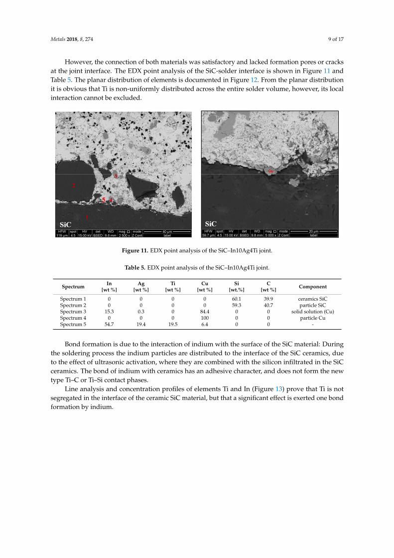
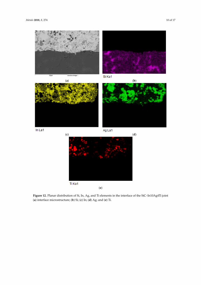
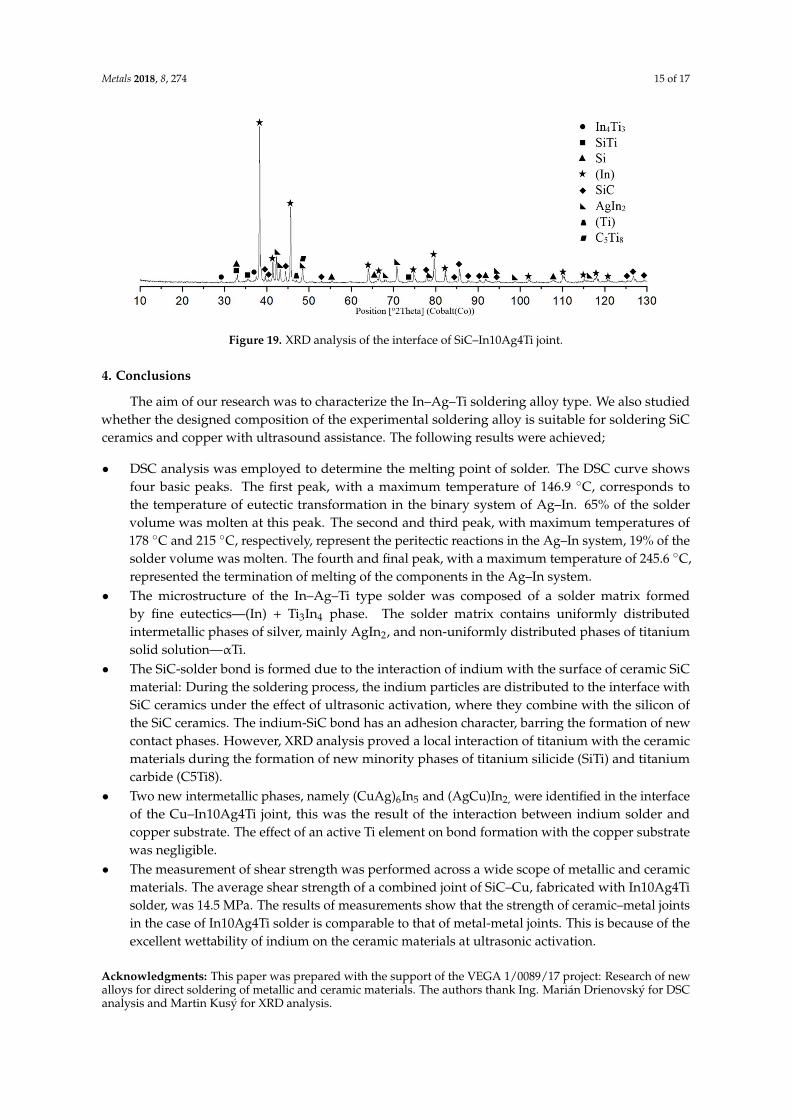