Embed Size (px)
Citation preview

This material is based upon work supported by the U.S. Department of Energy Office of Science under Cooperative Agreement DE-SC0000661, the State of Michigan and Michigan State University. Michigan State University designs and establishes FRIB as a DOE Office of Science National User Facility in support of the mission of the Office of Nuclear Physics.
F. Martia, P. Guetschowa, A. Hershcovitchb, Y. Momozakic, J. A. Nolena,c, C. B. Reedc, P.
Thiebergerb a Facility for Rare Isotope Beams, MSU,
b Brookhaven National Laboratory,
c Argonne National Laboratory
Charge Stripper Developments for FRIB

Brief description of FRIB Challenges of the FRIB charge stripper Options considered Development and current status of the liquid lithium charge stripper
• Film formation (at ANL) • Beam on film tests (at ANL and MSU) • Electromagnetic pump • Status of the construction
Development and current status of the helium gas charge stripper • Feasibility and initial measurements (at BNL) • Development and endurance tests (at MSU)
Summary
Outline
F. Marti, May 2015, IPAC15 , Slide 2

The Facility for Rare Isotope Beams is funded by DOE–SC Office of Nuclear Physics with contributions and cost share from Michigan State University
Key features are 400 kW beam power for all ions and E/A> 200 MeV/u
Separation of isotopes in-flight provides • Fast development
time for any isotope • All elements and
short half-lives • Fast, stopped, and
reaccelerated beams
What is FRIB?
F. Marti, May 2015, IPAC15 , Slide 3

FRIB Driver Linac Layout
F. Marti, May 2015, IPAC15 , Slide 4
A Superconducting Radio Frequency folded linac layout was chosen with two ECR ion sources located above the linac tunnel. A four vane RFQ will accelerate the ions to 0.5 MeV/u. The stripper is located at the end of Linac Segment 1 (β = 0.041 and 0.085 cavities). where ions have energies between 16 and 20 MeV/u. The bend will select multiple charge states of the stripped beam (up to five charge states for uranium ions) for simultaneous acceleration in the rest of the linac. After acceleration in Linac Segment 2 (β = 0.29 and 0.53) to energies of ~ 150 MeV/u the beam turns a 180 degree bend and into Linac Segment 3 (β = 0.53).
Stripper

Full beam diameter at the stripper ~ 3 mm.
Estimated stripper thickness for carbon film~ 3 µm .
Power deposition density on the stripper for uranium beam (400 kW final power) in carbon film is approximately 30 MW/cm3.
Heavy radiation damage to solids in this energy range (~ 16 MeV/u)
dE/dx orders of magnitude larger than for protons
Challenges of the FRIB Charge Stripper
F. Marti, May 2015, IPAC15 , Slide 5
Carbon foils after irradiation by Pb beam (~8 MeV/u)
Stripping energy

Solid carbon foils can be used only with low Z ions at low intensities We need to utilize a stripping media that doesn’t suffer radiation
damage to the material lattice and can remove the heat quickly Two options are available, liquids and gases For liquids, lithium is the best option.
• It has a relatively low melting point (181 C), low vapor pressure at that temperature (10-7 Pa), high boiling point (1342 C), high heat capacity and low viscosity.
• The negative aspect is that it is pyrophoric, safety concerns
For gases, helium is the best candidate. • The average charge state after stripping is higher than for heavier mass
gases (like N2 or Ar) • It is difficult to pump and expensive to replenish, we need to recover and
recirculate
Options considered
F. Marti, May 2015, IPAC15 , Slide 6

Originally proposed in 2003 by J. Nolen(a) (ANL) for the RIA driver linac
A series of experiments were performed at ANL under the DOE RIA R&D program (b). • Verified feasibility of the production of a thin lithium
film
A collaboration was established after MSU was selected to design and build FRIB and more R&D was performed to verify the stability and thickness (~12 µm, +/- 5% for 1 mm diameter spot) of the lithium film (c).
A later set of experiments demonstrated that the power deposition of a high power beam (protons) would not destroy the thin film (d).
Liquid lithium charge stripper development
F. Marti, May 2015, IPAC15 , Slide 7
a) 2003 Thin-film liquid-lithium stripper for the RIA driver linac. DOE RIA R&D proposal. b) Y. Momozaki et al., JINST 4 (2009) P04005 c) C. B. Reed at al., FRIB Lithium Stripper Thickness and Stability Measurements, ANL/NE-11/01 d) Y. Momozaki et al., J. Radioanal. Nucl. Chem. DOI 10.1007/s10967-015-4074-9
Li
Na
Hg

The major question we needed to answer was related to the possibility that the power deposited on the film by the beam would produce bubbles and destroy the film in the process
We borrowed the LEDA (LANL) proton source and adapted at MSU with a new beam line to produce a proton beam of 3 mm diameter and power density comparable to the power deposited by the uranium beam at the FRIB stripper. The source was then moved to ANL.
The proton beam (65 kV, 300 W) stopped completely in the lithium film. The highest power density split the film below the impact point, without disturbing the interaction volume.
Can the thin film survive the power deposition? YES
F. Marti, May 2015, IPAC15 , Slide 8
The LEDA proton beam coming from the right stops in the lithium film. Three different focusing settings are shown. The rightmost image shows film splitting

Stripper Film Produced by High Velocity Jet
F. Marti, May 2015, IPAC15 , Slide 9
Deflector
Lithium returns to pump
Stripped Beam
The thin lithium film needs to move very fast (~ 50 m/s) to remove the heat away from the impact point. This is achieved by producing a high pressure (~200 psi) lithium jet in a 0.5 mm diameter nozzle. The jet impinges on a flat deflector and produces the thin film.

Electromagnetic Pump Design
F. Marti, May 2015, IPAC15 , Slide 10
Sm Co Permanent magnets
Steel
Based on a indium/gallium pump designed and tested by R. Smither (ANL, 1995)

Assembly of Pump Magnet
F. Marti, May 2015, IPAC15 , Slide 11
We have performed the assembly of the pump before the helical coiled tube was available. Four hydraulic cylinders control the ring motion.
Large forces (~12,000 kg) have to be controlled during the assembly process.
Steel Permanent Magnets SmCo
The first ring is attracted to the lower cap. The following rings are repelled. The top cap is attracted with ~ 12,000 kg force.

Charge Stripper Design Has Been Finalized
F. Marti, May 2015, IPAC15 , Slide 12
Beam
2 m
Safety is a main concern. Primary chamber is contained in a secondary vessel continuously filled with inert argon gas.
Argon Tank
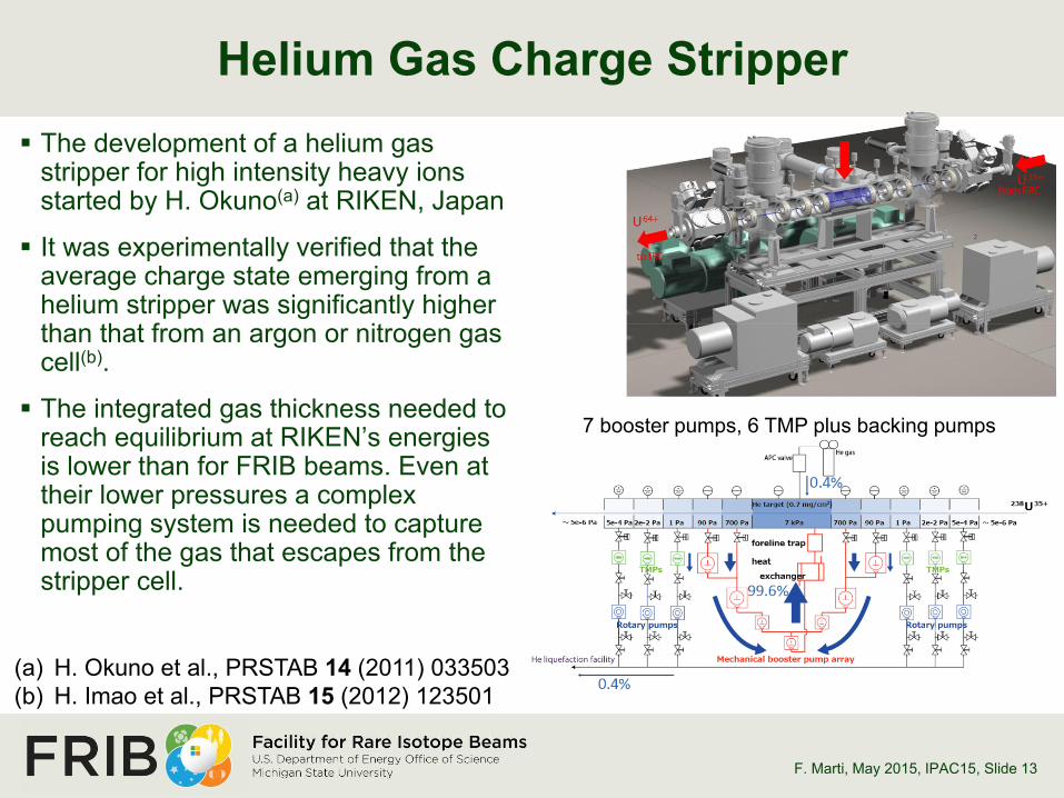
Helium Gas Charge Stripper
F. Marti, May 2015, IPAC15 , Slide 13
The development of a helium gas stripper for high intensity heavy ions started by H. Okuno(a) at RIKEN, Japan
It was experimentally verified that the average charge state emerging from a helium stripper was significantly higher than that from an argon or nitrogen gas cell(b).
The integrated gas thickness needed to reach equilibrium at RIKEN’s energies is lower than for FRIB beams. Even at their lower pressures a complex pumping system is needed to capture most of the gas that escapes from the stripper cell.
(a) H. Okuno et al., PRSTAB 14 (2011) 033503 (b) H. Imao et al., PRSTAB 15 (2012) 123501
7 booster pumps, 6 TMP plus backing pumps

How to Reduce the Helium Loss?
F. Marti, May 2015, IPAC15 , Slide 14
P. Thieberger(a) (BNL) proposed the use of plasma windows to reduce the conductance from the gas cell to the rest of the beamline in the FRIB stripper.
A. Hershcovitch (BNL) developed the original concept of the plasma window(b). It consist of a wall stabilized plasma that heats the gas trying to escape from the high pressure cell. The increased velocity of the gas achieves a choked flow condition and a higher viscosity, limiting the mass flow.
(a) P. Thieberger, Stripper and Target Technology for High Power Heavy Ion Beams Workshop, East Lansing (2009)
(b) A. Hershcovitch, J. Appl. Phys. 79, 5283 (1995).
Cathode
Cooling plates
Low pressure
Gas cell high
pressure
Plasma
Anode
Beam

Possible configuration for FRIB
F. Marti, May 2015, IPAC15 , Slide 15
The high velocity helium flow is needed to avoid a large change in gas density due to the power loss of the beam in the gas
Recirculator and heat exchanger

Results from R&D at BNL for a 6 mm Aperture
F. Marti, May 2015, IPAC15 , Slide 16
A conductance reduction factor of 8 was achieved at 30 A
Results from an 8 hour test
Discharge power dissipated in each plate of the 6 mm aperture plasma window as measured by the cooling water temperature increase.
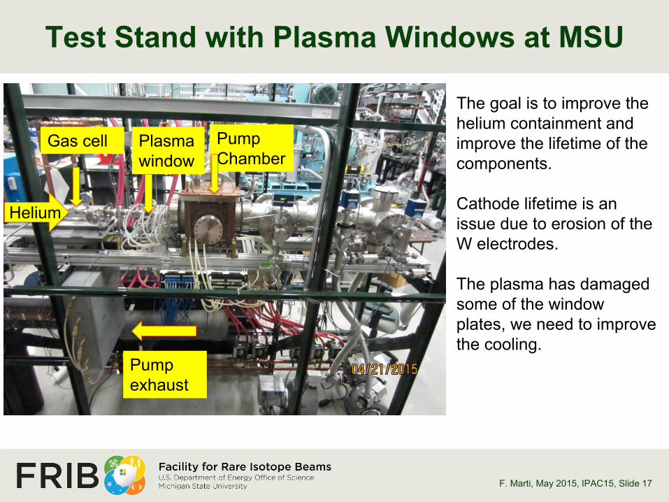
Test Stand with Plasma Windows at MSU
F. Marti, May 2015, IPAC15 , Slide 17
Gas cell Plasma window
Pump Chamber
Pump exhaust
The goal is to improve the helium containment and improve the lifetime of the components. Cathode lifetime is an issue due to erosion of the W electrodes. The plasma has damaged some of the window plates, we need to improve the cooling.
Helium

The baseline design of the charge stripper for FRIB is based on a liquid lithium film • Development has been performed in collaboration with ANL • A charge stripper module is under construction and we expect to start
commissioning by the end of the 2015 • The goal is to determine a maintenance plan and reliability issues • The liquid lithium charge stripper will be ready for installation in the tunnel in
mid 2017
An alternative helium gas stripper with plasma windows is being researched • A research program in collaboration with BNL confirmed its feasibility • We continue its development at MSU
Summary
F. Marti, May 2015, IPAC15 , Slide 18