Embed Size (px)
Citation preview
7
CHARGING SYSTEM
GENERALThe charging system consists of the alternator and regulator.See page 7-25 for charging system circuits.
Alternator
The alternator consists of two main components: the rotorwhich is mounted on the engine sprocket shaft, and the sta-tor, which is bolted to the engine crankcase.
Voltage Regulator
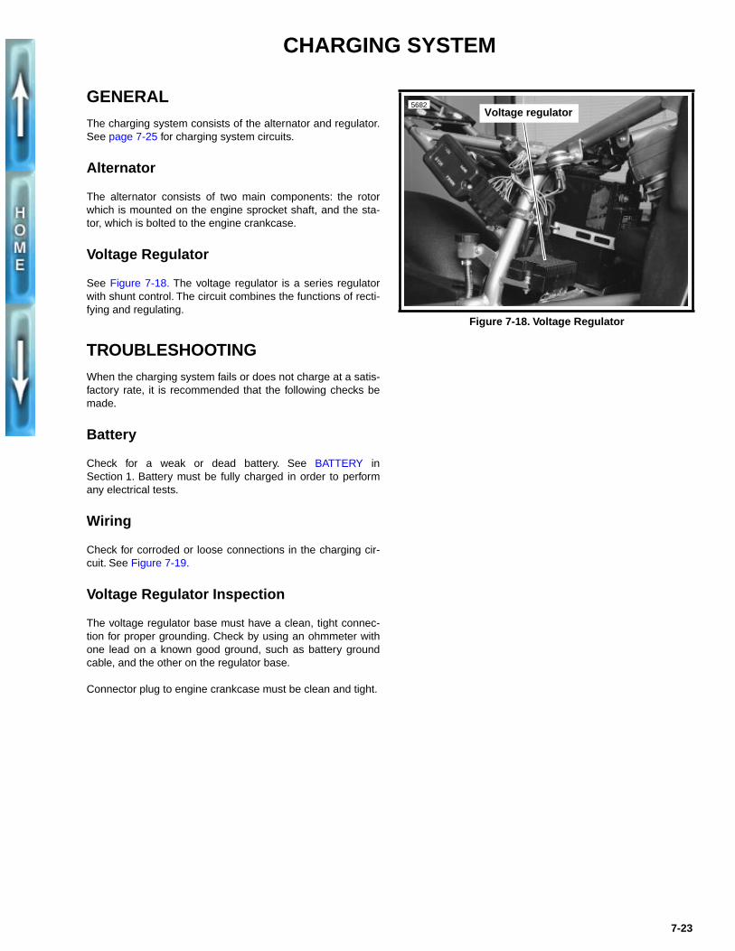
See Figure 7-18. The voltage regulator is a series regulatorwith shunt control. The circuit combines the functions of recti-fying and regulating.
TROUBLESHOOTINGWhen the charging system fails or does not charge at a satis-factory rate, it is recommended that the following checks bemade.
Battery
Check for a weak or dead battery. See BATTERY inSection 1. Battery must be fully charged in order to performany electrical tests.
Wiring
Check for corroded or loose connections in the charging cir-cuit. See Figure 7-19.
Voltage Regulator Inspection
The voltage regulator base must have a clean, tight connec-tion for proper grounding. Check by using an ohmmeter withone lead on a known good ground, such as battery groundcable, and the other on the regulator base.
Connector plug to engine crankcase must be clean and tight.
Figure 7-18. Voltage Regulator
5682Voltage regulator
7-23
7
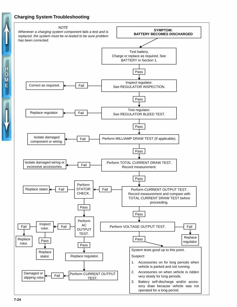
Charging System Troubleshooting
NOTEWhenever a charging system component fails a test and isreplaced, the system must be re-tested to be sure problemhas been corrected.
-24
Fail
Fail
Fail
Fail Fail
FailFail
Fail
Pass
PassPass
Replace regulator.
SYMPTOM:BATTERY BECOMES DISCHARGED
Test battery. Charge or replace as required. See
BATTERY in Section 1.
Pass
Pass
Fail
Correct as required.
Inspect regulator.See REGULATOR INSPECTION.
Replace regulator.
Test regulator.See REGULATOR BLEED TEST.
Pass
Isolate damaged component or wiring.
Perform MILLIAMP DRAW TEST (If applicable).
Pass
Isolate damaged wiring or excessive accessories.
Perform TOTAL CURRENT DRAW TEST.Record measurement.
Pass
Replace stator.
Perform STATOR CHECK.Perform CURRENT OUTPUT TEST. Record measurement and compare with TOTAL CURRENT DRAW TEST before
proceeding.
Fail
Pass
Pass
Replace rotor.Inspect rotor.
System tests good up to this point.
Suspect:
1. Accessories on for long periods when
Replace stator.
PerformAC
OUTPUT TEST.
vehicle is parked and not
2. Accessories on when vehvery slowly for long period
3. Battery self-discharge asory draw because vehoperated for a long period
Replace regulator.
Perform VOLTAGE OUTPUT TEST.
running.
icle is riddens.
nd/or acces-
Damaged or slipping rotor.
Perform CURRENT OUTPUT TEST.
icle was not.
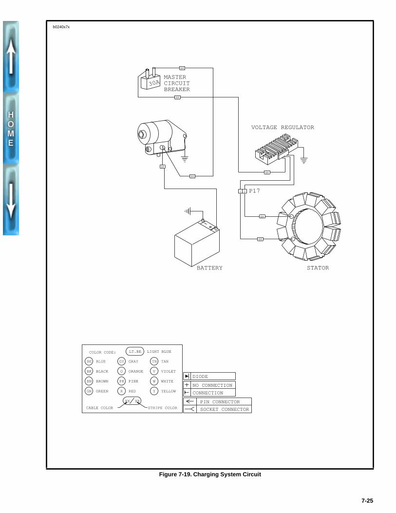
Figure 7-19. Charging System Circuit
1 2
30AMASTER CIRCUIT BREAKER
P17
BK
BK
BK
VOLTAGE REGULATOR
BK
BK
BK
BK
STATORBATTERY
LT.BE LIGHT BLUE
CABLE COLOR
BE
COLOR CODE:
BK
BN
GN
GY
O
BLUE
BLACK
BROWN
GREEN
GRAY
ORANGE
PINK
RED
TAN
VIOLET
WHITE
YELLOW
PK
R
TN
V
W
Y
STRIPE COLOR
XX XX PIN CONNECTOR
SOCKET CONNECTOR
NO CONNECTION
CONNECTION
DIODE
b0240x7x
7-25
TESTING
Voltage Regulator Bleed Test
Be sure regulator is connected to battery. Unplug regulatorconnector to engine crankcase. Use a trouble light and touchone probe to a known good ground and the other to the regu-lator pins, one at a time. If light glows, replace regulator.
Milliampere Draw Test
NOTE
Be sure accessories are not wired so they stay on at all times.Check for this by connecting ammeter between negative bat-tery terminal and battery.
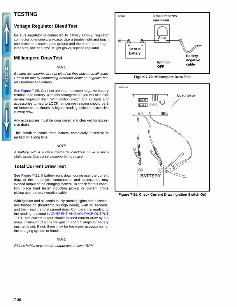
See Figure 7-20. Connect ammeter between negative batteryterminal and battery. With this arrangement, you will also pickup any regulator drain. With ignition switch and all lights andaccessories turned to LOCK, amperage reading should be 3milliamperes maximum. A higher reading indicates excessivecurrent draw.
Any accessories must be considered and checked for exces-sive drain.
This condition could drain battery completely if vehicle isparked for a long time.
NOTE
A battery with a surface discharge condition could suffer astatic drain. Correct by cleaning battery case.
Total Current Draw Test
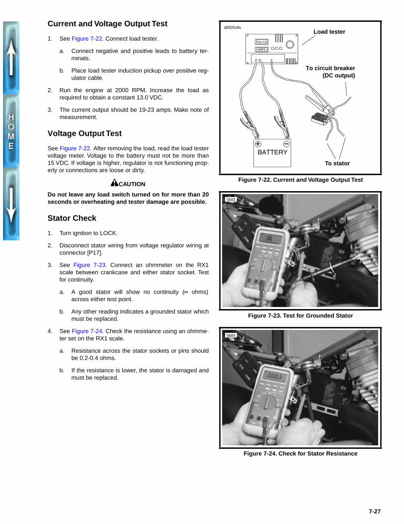
See Figure 7-21. If battery runs down during use, the currentdraw of the motorcycle components and accessories mayexceed output of the charging system. To check for this condi-tion, place load tester induction pickup or current probepickup over battery negative cable.
With ignition and all continuously running lights and accesso-ries turned on (headlamp on high beam), wait 10 seconds,and then read the total current draw. Compare this reading tothe reading obtained in CURRENT AND VOLTAGE OUTPUTTEST. The current output should exceed current draw by 6.5amps, minimum (3 amps for ignition and 3.5 amps for batterymaintenance). If not, there may be too many accessories forthe charging system to handle.
NOTE
Rider’s habits may require output test at lower RPM.
Figure 7-20. Milliampere Draw Test
Figure 7-21. Check Current Draw (Ignition Switch On)
flt0808
Amp
12 VDCbattery
IgnitionOFF
Battery negative cable
3 milliamperesmaximum
d0004x8x
Load tester
7-26
Current and Voltage Output Test
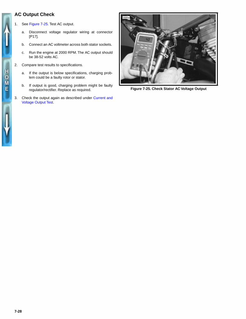
1. See Figure 7-22. Connect load tester.
a. Connect negative and positive leads to battery ter-minals.
b. Place load tester induction pickup over positive reg-ulator cable.
2. Run the engine at 2000 RPM. Increase the load asrequired to obtain a constant 13.0 VDC.
3. The current output should be 19-23 amps. Make note ofmeasurement.
Voltage Output Test
See Figure 7-22. After removing the load, read the load testervoltage meter. Voltage to the battery must not be more than15 VDC. If voltage is higher, regulator is not functioning prop-erly or connections are loose or dirty.
1CAUTION
Do not leave any load switch turned on for more than 20seconds or overheating and tester damage are possible.
Stator Check
1. Turn ignition to LOCK.
2. Disconnect stator wiring from voltage regulator wiring atconnector [P17].
3. See Figure 7-23. Connect an ohmmeter on the RX1scale between crankcase and either stator socket. Testfor continuity.
a. A good stator will show no continuity (∞ ohms)across either test point.
b. Any other reading indicates a grounded stator whichmust be replaced.
4. See Figure 7-24. Check the resistance using an ohmme-ter set on the RX1 scale.
a. Resistance across the stator sockets or pins shouldbe 0.2-0.4 ohms.
b. If the resistance is lower, the stator is damaged andmust be replaced.
Figure 7-22. Current and Voltage Output Test
Figure 7-23. Test for Grounded Stator
Figure 7-24. Check for Stator Resistance
d0005x8x
To circuit breaker(DC output)
To stator
Load tester
5683
5684
7-27
AC Output Check
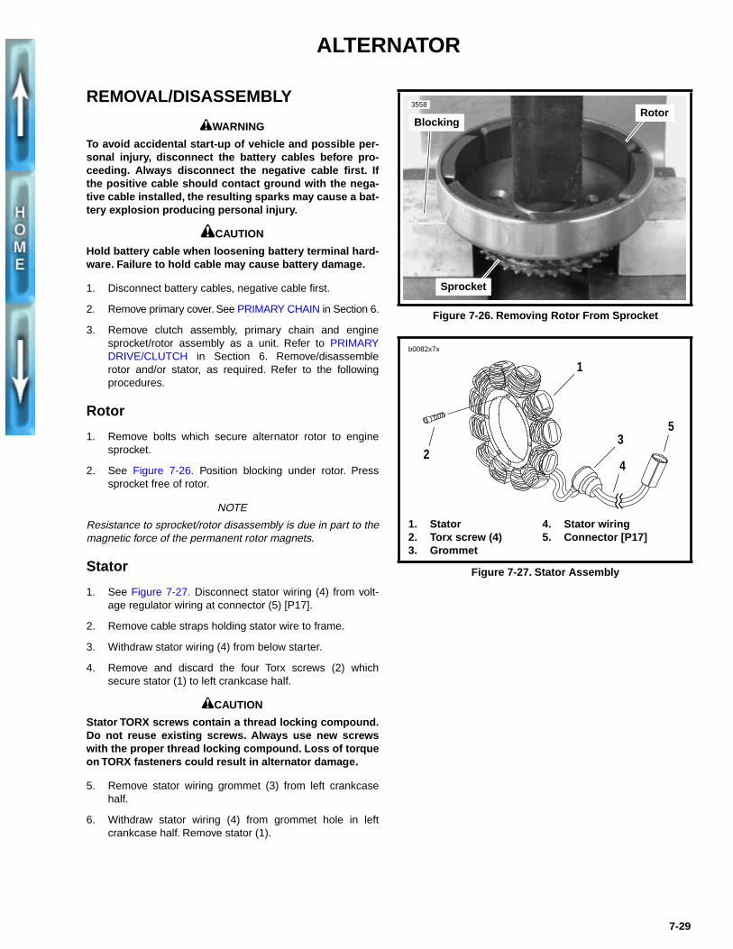
1. See Figure 7-25. Test AC output.
a. Disconnect voltage regulator wiring at connector[P17].
b. Connect an AC voltmeter across both stator sockets.
c. Run the engine at 2000 RPM. The AC output shouldbe 38-52 volts AC.
2. Compare test results to specifications.
a. If the output is below specifications, charging prob-lem could be a faulty rotor or stator.
b. If output is good, charging problem might be faultyregulator/rectifier. Replace as required.
3. Check the output again as described under Current andVoltage Output Test.
Figure 7-25. Check Stator AC Voltage Output
5685a
7-28
ALTERNATOR
REMOVAL/DISASSEMBLY
1WARNING
To avoid accidental start-up of vehicle and possible per-sonal injury, disconnect the battery cables before pro-ceeding. Always disconnect the negative cable first. Ifthe positive cable should contact ground with the nega-tive cable installed, the resulting sparks may cause a bat-tery explosion producing personal injury.
1CAUTION
Hold battery cable when loosening battery terminal hard-ware. Failure to hold cable may cause battery damage.
1. Disconnect battery cables, negative cable first.
2. Remove primary cover. See PRIMARY CHAIN in Section 6.
3. Remove clutch assembly, primary chain and enginesprocket/rotor assembly as a unit. Refer to PRIMARYDRIVE/CLUTCH in Section 6. Remove/disassemblerotor and/or stator, as required. Refer to the followingprocedures.
Rotor
1. Remove bolts which secure alternator rotor to enginesprocket.
2. See Figure 7-26. Position blocking under rotor. Presssprocket free of rotor.
NOTE
Resistance to sprocket/rotor disassembly is due in part to themagnetic force of the permanent rotor magnets.
Stator
1. See Figure 7-27. Disconnect stator wiring (4) from volt-age regulator wiring at connector (5) [P17].
2. Remove cable straps holding stator wire to frame.
3. Withdraw stator wiring (4) from below starter.
4. Remove and discard the four Torx screws (2) whichsecure stator (1) to left crankcase half.
1CAUTION
Stator TORX screws contain a thread locking compound.Do not reuse existing screws. Always use new screwswith the proper thread locking compound. Loss of torqueon TORX fasteners could result in alternator damage.
5. Remove stator wiring grommet (3) from left crankcasehalf.
6. Withdraw stator wiring (4) from grommet hole in leftcrankcase half. Remove stator (1).
Figure 7-26. Removing Rotor From Sprocket
Figure 7-27. Stator Assembly
Sprocket
3558Rotor
Blocking
1. Stator2. Torx screw (4)3. Grommet
4. Stator wiring5. Connector [P17]
b0082x7x
1
35
42
7-29
CLEANING, INSPECTION AND REPAIR
1CAUTIONDo not strike or drop alternator rotor or damage to mag-net adhesive may occur. Magnet adhesive damage canresult in rotor failure.
1. Clean rotor with a petroleum-base solvent. Remove allforeign material from rotor magnets. Replace rotor if rotormagnets are cracked or loose.
2. Clean stator by wiping with a clean cloth.
3. Examine stator leads for cracked or damaged insulation.
NOTEThe rotor and stator can be replaced individually if either isdamaged.
ASSEMBLY/INSTALLATIONDepending on whether the rotor, the stator, or both the rotorand stator were removed/disassembled, perform the applica-ble procedures which follow:
1. See Figure 7-27. Feed stator wiring (4) with attachedgrommet (3) into open grommet hole in left crankcasehalf.
2. Apply a light coating of clean engine oil or chaincaselubricant to grommet. Install grommet into hole in leftcrankcase half.
1CAUTIONStator TORX screws contain a thread locking compound.Do not reuse existing screws. Always use new screwswith the proper thread locking compound. Loss of torqueon TORX fasteners could result in alternator damage.
3. Position stator (1) on left crankcase half. Secure statorusing four new Torx screws (2). Tighten screws to30-40 in-lbs (3.4-3.5 Nm).
4. Route stator wiring (4) below starter to frame upright.
NOTETemporarily attach a thin flexible “feed” or mechanic’s wire tothe connector end of the stator wiring to assist in the routingof the wiring
5. Route stator wiring upward along side of frame upright.Connect stator wiring connector [P17] to voltage regulator.
6. Secure stator wiring, along with any other wires andhoses routed in the same location, to frame using cablestraps.
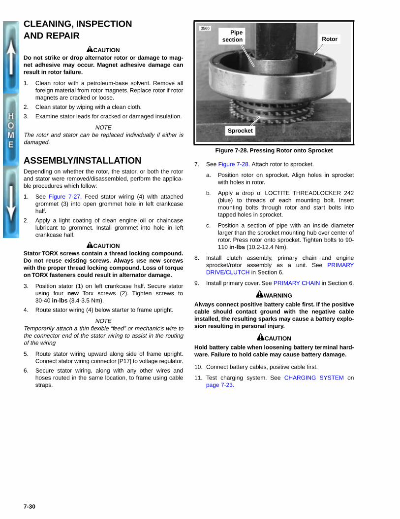
7. See Figure 7-28. Attach rotor to sprocket.
a. Position rotor on sprocket. Align holes in sprocketwith holes in rotor.
b. Apply a drop of LOCTITE THREADLOCKER 242(blue) to threads of each mounting bolt. Insertmounting bolts through rotor and start bolts intotapped holes in sprocket.
c. Position a section of pipe with an inside diameterlarger than the sprocket mounting hub over center ofrotor. Press rotor onto sprocket. Tighten bolts to 90-110 in-lbs (10.2-12.4 Nm).
8. Install clutch assembly, primary chain and enginesprocket/rotor assembly as a unit. See PRIMARYDRIVE/CLUTCH in Section 6.
9. Install primary cover. See PRIMARY CHAIN in Section 6.
1WARNING
Always connect positive battery cable first. If the positivecable should contact ground with the negative cableinstalled, the resulting sparks may cause a battery explo-sion resulting in personal injury.
1CAUTION
Hold battery cable when loosening battery terminal hard-ware. Failure to hold cable may cause battery damage.
10. Connect battery cables, positive cable first.
11. Test charging system. See CHARGING SYSTEM onpage 7-23.
Figure 7-28. Pressing Rotor onto Sprocket
Sprocket
3560
RotorPipe
section
7-30
VOLTAGE REGULATOR
GENERALThe voltage regulator is on the right side next to the battery.The voltage regulator is not repairable. Replace the unit if itfails.
REMOVAL
1WARNINGTo avoid accidental start-up of vehicle and possible per-sonal injury, disconnect the battery cables before pro-ceeding. Always disconnect the negative cable first. Ifthe positive cable should contact ground with the nega-tive cable installed, the resulting sparks may cause a bat-tery explosion producing personal injury.
1CAUTIONHold battery cable when loosening battery terminal hard-ware. Failure to hold cable may cause battery damage.
1. Disconnect battery cables, negative cable first.
1CAUTIONWhen disconnecting the alternator stator wiring, pullapart the connector by firmly grasping both connectorhalves. Do not pull on leads or damage to the wires and/or terminals may result.
2. See Figure 7-29. Disconnect voltage regulator connector[P17] from alternator stator wiring.
3. Disconnect charging wire (black) from gold terminal onthe main circuit breaker.
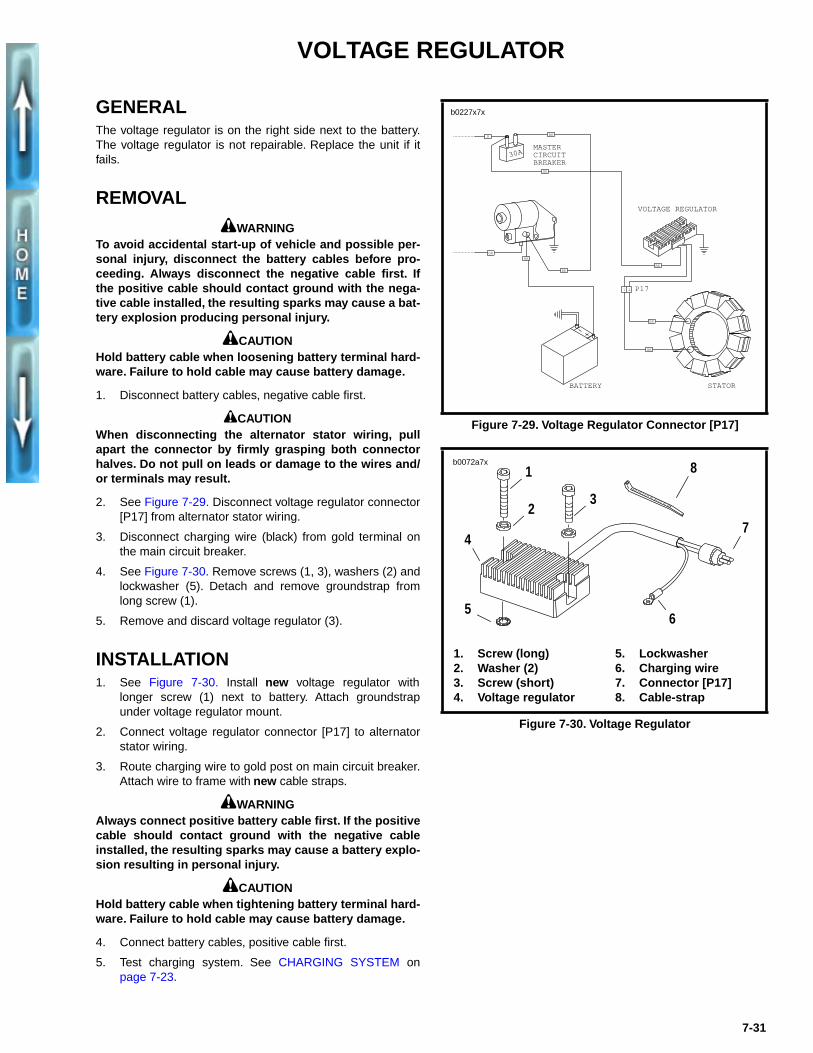
4. See Figure 7-30. Remove screws (1, 3), washers (2) andlockwasher (5). Detach and remove groundstrap fromlong screw (1).
5. Remove and discard voltage regulator (3).
INSTALLATION1. See Figure 7-30. Install new voltage regulator with
longer screw (1) next to battery. Attach groundstrapunder voltage regulator mount.
2. Connect voltage regulator connector [P17] to alternatorstator wiring.
3. Route charging wire to gold post on main circuit breaker.Attach wire to frame with new cable straps.
1WARNINGAlways connect positive battery cable first. If the positivecable should contact ground with the negative cableinstalled, the resulting sparks may cause a battery explo-sion resulting in personal injury.
1CAUTIONHold battery cable when tightening battery terminal hard-ware. Failure to hold cable may cause battery damage.
4. Connect battery cables, positive cable first.
5. Test charging system. See CHARGING SYSTEM onpage 7-23.
Figure 7-29. Voltage Regulator Connector [P17]
Figure 7-30. Voltage Regulator
b0227x7x
1 2
30AMASTER CIRCUIT BREAKER
R
P17
BK
BK
BK
GN
VOLTAGE REGULATOR
BK
BK
BK
BK
STATORBATTERY
1. Screw (long)2. Washer (2)3. Screw (short)4. Voltage regulator
5. Lockwasher6. Charging wire7. Connector [P17]8. Cable-strap
b0072a7x
7
81
2
56
4
3
7-31
BATTERY
GENERAL1WARNING
● Batteries contain sulfuric acid which can cause severeburns. Avoid contact with skin, eyes or clothing.
● Batteries produce explosive hydrogen gas at alltimes, especially when being charged. Keep ciga-rettes, open flame and sparks away from the batteryat all times. Ventilate area when charging battery.Always protect hands and protect eyes with shield orgoggles when working near a battery or acid. KEEPBATTERIES AND ACID OUT OF THE REACH OF CHIL-DREN!
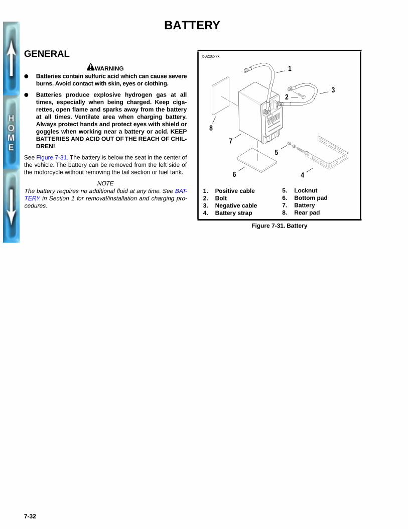
See Figure 7-31. The battery is below the seat in the center ofthe vehicle. The battery can be removed from the left side ofthe motorcycle without removing the tail section or fuel tank.
NOTEThe battery requires no additional fluid at any time. See BAT-TERY in Section 1 for removal/installation and charging pro-cedures.
Figure 7-31. Battery
b0228x7x
1
1. Positive cable2. Bolt3. Negative cable4. Battery strap
5. Locknut6. Bottom pad7. Battery8. Rear pad
3
4
2
5
6
7
8
7-32
HEADLAMP
REMOVAL
Headlamp and Bulbs
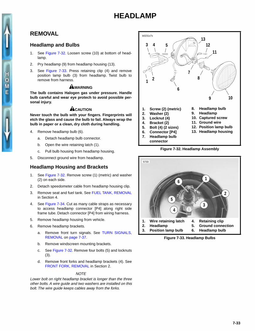
1. See Figure 7-32. Loosen screw (10) at bottom of head-lamp.
2. Pry headlamp (9) from headlamp housing (13).
3. See Figure 7-33. Press retaining clip (4) and removeposition lamp bulb (3) from headlamp. Twist bulb toremove from harness.
1WARNINGThe bulb contains Halogen gas under pressure. Handlebulb careful and wear eye protech to avoid possible per-sonal injury.
1CAUTIONNever touch the bulb with your fingers. Fingerprints willetch the glass and cause the bulb to fail. Always wrap thebulb in paper or a clean, dry cloth during handling.
4. Remove headlamp bulb (6).
a. Detach headlamp bulb connector.
b. Open the wire retaining latch (1).
c. Pull bulb housing from headlamp housing.
5. Disconnect ground wire from headlamp.
Headlamp Housing and Brackets
1. See Figure 7-32. Remove screw (1) (metric) and washer(2) on each side.
2. Detach speedometer cable from headlamp housing clip.
3. Remove seat and fuel tank. See FUEL TANK, REMOVALin Section 4.
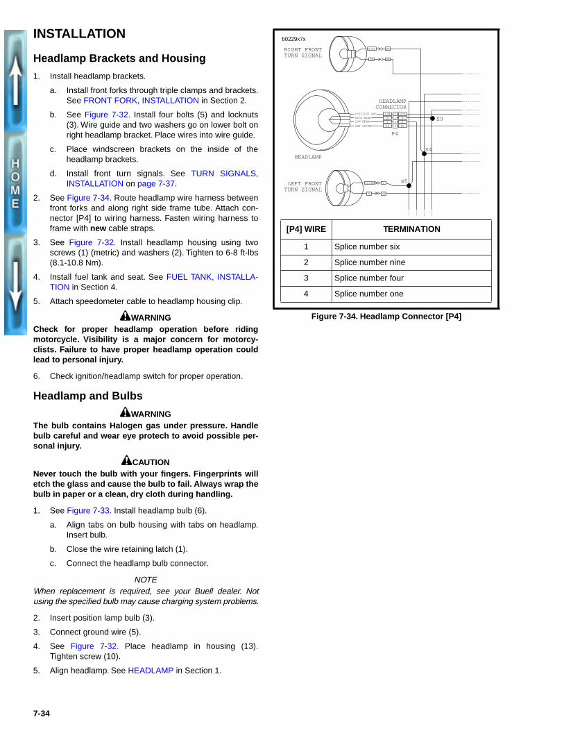
4. See Figure 7-34. Cut as many cable straps as necessaryto access headlamp connector [P4] along right sideframe tube. Detach connector [P4] from wiring harness.
5. Remove headlamp housing from vehicle.
6. Remove headlamp brackets.
a. Remove front turn signals. See TURN SIGNALS,REMOVAL on page 7-37.
b. Remove windscreen mounting brackets.
c. See Figure 7-32. Remove four bolts (5) and locknuts(3).
d. Remove front forks and headlamp brackets (4). SeeFRONT FORK, REMOVAL in Section 2.
NOTELower bolt on right headlamp bracket is longer than the threeother bolts. A wire guide and two washers are installed on thisbolt. The wire guide keeps cables away from the forks.
Figure 7-32. Headlamp Assembly
Figure 7-33. Headlamp Bulbs
b0231x7x
1 2
3 4 5
6
11
78
9
1213
1. Screw (2) (metric)2. Washer (2)3. Locknut (4)4. Bracket (2)5. Bolt (4) (2 sizes)6. Connector [P4]7. Headlamp bulb
connector
8. Headlamp bulb9. Headlamp10. Captured screw11. Ground wire12. Position lamp bulb13. Headlamp housing
10
1
5733
6
53
1. Wire retaining latch2. Headlamp3. Position lamp bulb
4. Retaining clip5. Ground connection6. Headlamp bulb
2
4
7-33
INSTALLATION
Headlamp Brackets and Housing
1. Install headlamp brackets.
a. Install front forks through triple clamps and brackets.See FRONT FORK, INSTALLATION in Section 2.
b. See Figure 7-32. Install four bolts (5) and locknuts(3). Wire guide and two washers go on lower bolt onright headlamp bracket. Place wires into wire guide.
c. Place windscreen brackets on the inside of theheadlamp brackets.
d. Install front turn signals. See TURN SIGNALS,INSTALLATION on page 7-37.
2. See Figure 7-34. Route headlamp wire harness betweenfront forks and along right side frame tube. Attach con-nector [P4] to wiring harness. Fasten wiring harness toframe with new cable straps.
3. See Figure 7-32. Install headlamp housing using twoscrews (1) (metric) and washers (2). Tighten to 6-8 ft-lbs(8.1-10.8 Nm).
4. Install fuel tank and seat. See FUEL TANK, INSTALLA-TION in Section 4.
5. Attach speedometer cable to headlamp housing clip.
1WARNINGCheck for proper headlamp operation before ridingmotorcycle. Visibility is a major concern for motorcy-clists. Failure to have proper headlamp operation couldlead to personal injury.
6. Check ignition/headlamp switch for proper operation.
Headlamp and Bulbs
1WARNINGThe bulb contains Halogen gas under pressure. Handlebulb careful and wear eye protech to avoid possible per-sonal injury.
1CAUTIONNever touch the bulb with your fingers. Fingerprints willetch the glass and cause the bulb to fail. Always wrap thebulb in paper or a clean, dry cloth during handling.
1. See Figure 7-33. Install headlamp bulb (6).
a. Align tabs on bulb housing with tabs on headlamp.Insert bulb.
b. Close the wire retaining latch (1).
c. Connect the headlamp bulb connector.
NOTEWhen replacement is required, see your Buell dealer. Notusing the specified bulb may cause charging system problems.
2. Insert position lamp bulb (3).
3. Connect ground wire (5).
4. See Figure 7-32. Place headlamp in housing (13).Tighten screw (10).
5. Align headlamp. See HEADLAMP in Section 1.
Figure 7-34. Headlamp Connector [P4]
S5
BKBE
VLT.BE
S9
S4
P4
W
BK
Y2
3
4
O/W1
BK
W
O/W
Y
POSITION LMP
HIGH BEAMLOW BEAM
LMP GROUND
HEADLAMP
HEADLAMP CONNECTOR
LEFT FRONT TURN SIGNAL
RIGHT FRONT TURN SIGNAL
BNR/BK
KBBE
[P4] WIRE TERMINATION
1 Splice number six
2 Splice number nine
3 Splice number four
4 Splice number one
b0229x7x
7-34
TAIL LAMP
REMOVAL/DISASSEMBLY
Tail Lamp
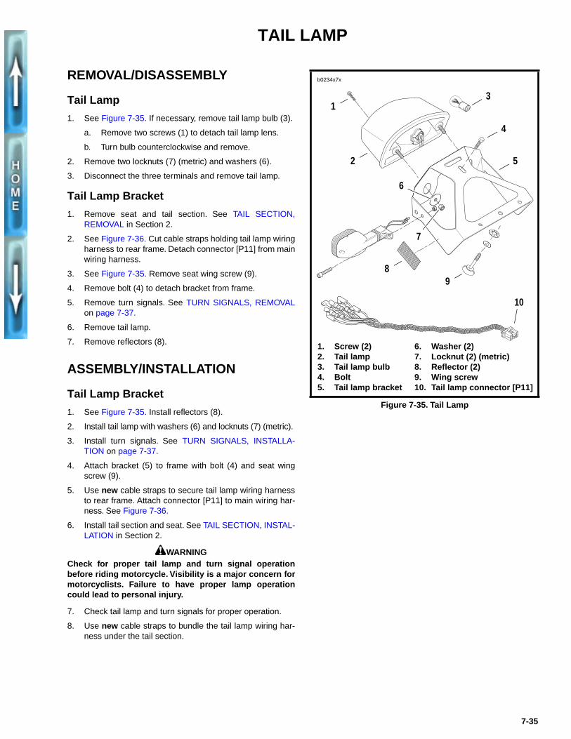
1. See Figure 7-35. If necessary, remove tail lamp bulb (3).
a. Remove two screws (1) to detach tail lamp lens.
b. Turn bulb counterclockwise and remove.
2. Remove two locknuts (7) (metric) and washers (6).
3. Disconnect the three terminals and remove tail lamp.
Tail Lamp Bracket
1. Remove seat and tail section. See TAIL SECTION,REMOVAL in Section 2.
2. See Figure 7-36. Cut cable straps holding tail lamp wiringharness to rear frame. Detach connector [P11] from mainwiring harness.
3. See Figure 7-35. Remove seat wing screw (9).
4. Remove bolt (4) to detach bracket from frame.
5. Remove turn signals. See TURN SIGNALS, REMOVALon page 7-37.
6. Remove tail lamp.
7. Remove reflectors (8).
ASSEMBLY/INSTALLATION
Tail Lamp Bracket
1. See Figure 7-35. Install reflectors (8).
2. Install tail lamp with washers (6) and locknuts (7) (metric).
3. Install turn signals. See TURN SIGNALS, INSTALLA-TION on page 7-37.
4. Attach bracket (5) to frame with bolt (4) and seat wingscrew (9).
5. Use new cable straps to secure tail lamp wiring harnessto rear frame. Attach connector [P11] to main wiring har-ness. See Figure 7-36.
6. Install tail section and seat. See TAIL SECTION, INSTAL-LATION in Section 2.
1WARNINGCheck for proper tail lamp and turn signal operationbefore riding motorcycle. Visibility is a major concern formotorcyclists. Failure to have proper lamp operationcould lead to personal injury.
7. Check tail lamp and turn signals for proper operation.
8. Use new cable straps to bundle the tail lamp wiring har-ness under the tail section.
Figure 7-35. Tail Lamp
b0234x7x
1. Screw (2)2. Tail lamp3. Tail lamp bulb4. Bolt5. Tail lamp bracket
1
2
89
3
4
5
6
7
10
6. Washer (2)7. Locknut (2) (metric)8. Reflector (2)9. Wing screw10. Tail lamp connector [P11]
7-35
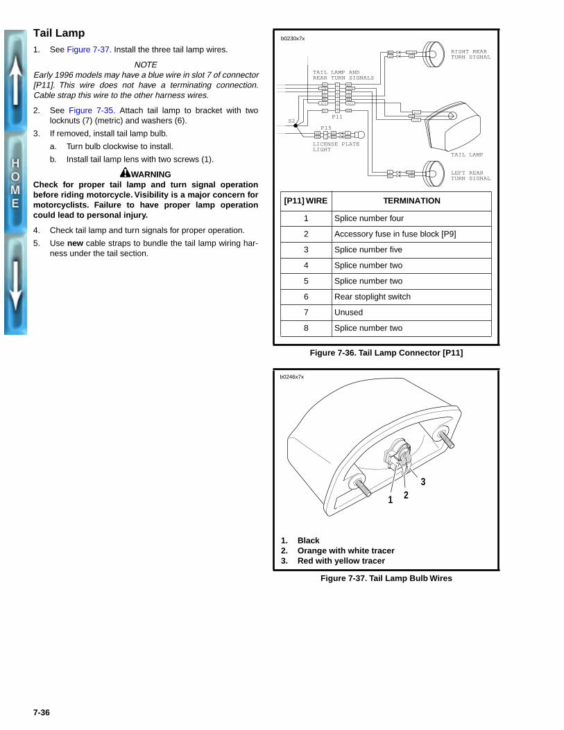
Tail Lamp1. See Figure 7-37. Install the three tail lamp wires.
NOTEEarly 1996 models may have a blue wire in slot 7 of connector[P11]. This wire does not have a terminating connection.Cable strap this wire to the other harness wires.
2. See Figure 7-35. Attach tail lamp to bracket with twolocknuts (7) (metric) and washers (6).
3. If removed, install tail lamp bulb.
a. Turn bulb clockwise to install.
b. Install tail lamp lens with two screws (1).
1WARNINGCheck for proper tail lamp and turn signal operationbefore riding motorcycle. Visibility is a major concern formotorcyclists. Failure to have proper lamp operationcould lead to personal injury.
4. Check tail lamp and turn signals for proper operation.
5. Use new cable straps to bundle the tail lamp wiring har-ness under the tail section.
Figure 7-36. Tail Lamp Connector [P11]
Figure 7-37. Tail Lamp Bulb Wires
RIGHT REAR TURN SIGNAL
1
2
3
4
5
6
78
P11BK BK
BK
V
R/Y
BN
V
O/W
BK
BK
R/Y
V
BK
BK
1
2
P15BE BE Y
BK BK BK
LICENSE PLATE LIGHT
TAIL LAMP AND REAR TURN SIGNALS
R/Y
BKO/W
BE
R/BK
TAIL LAMP
LEFT REAR TURN SIGNAL
BEBK
LT.BE
BNO/W
BN
S2
[P11] WIRE TERMINATION
1 Splice number four
2 Accessory fuse in fuse block [P9]
3 Splice number five
4 Splice number two
5 Splice number two
6 Rear stoplight switch
7 Unused
8 Splice number two
b0230x7x
1. Black 2. Orange with white tracer 3. Red with yellow tracer
1 23
b0246x7x
7-36
TURN SIGNALS
REMOVAL
Front1. Remove headlamp mounting screws (metric) and washers.
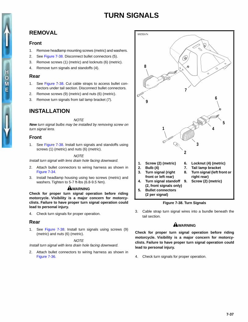
2. See Figure 7-38. Disconnect bullet connectors (5).
3. Remove screws (1) (metric) and locknuts (6) (metric).
4. Remove turn signals and standoffs (4).
Rear1. See Figure 7-38. Cut cable straps to access bullet con-
nectors under tail section. Disconnect bullet connectors.
2. Remove screws (9) (metric) and nuts (6) (metric).
3. Remove turn signals from tail lamp bracket (7).
INSTALLATIONNOTE
New turn signal bulbs may be installed by removing screw onturn signal lens.
Front1. See Figure 7-38. Install turn signals and standoffs using
screws (1) (metric) and nuts (6) (metric).
NOTEInstall turn signal with lens drain hole facing downward.
2. Attach bullet connectors to wiring harness as shown inFigure 7-34.
3. Install headlamp housing using two screws (metric) andwashers. Tighten to 5-7 ft-lbs (6.8-9.5 Nm).
1WARNINGCheck for proper turn signal operation before ridingmotorcycle. Visibility is a major concern for motorcy-clists. Failure to have proper turn signal operation couldlead to personal injury.
4. Check turn signals for proper operation.
Rear1. See Figure 7-38. Install turn signals using screws (9)
(metric) and nuts (6) (metric).
NOTEInstall turn signal with lens drain hole facing downward.
2. Attach bullet connectors to wiring harness as shown inFigure 7-36.
3. Cable strap turn signal wires into a bundle beneath thetail section.
1WARNING
Check for proper turn signal operation before ridingmotorcycle. Visibility is a major concern for motorcy-clists. Failure to have proper turn signal operation couldlead to personal injury.
4. Check turn signals for proper operation.
Figure 7-38. Turn Signals
b0232x7x
8
7
4
3
2
1
69
1. Screw (2) (metric)2. Bulb (4)3. Turn signal (right
front or left rear)4. Turn signal standoff
(2, front signals only)5. Bullet connectors
(2 per signal)
6. Locknut (4) (metric) 7. Tail lamp bracket8. Turn signal (left front or
right rear)9. Screw (2) (metric)
5
7-37
TURN SIGNAL FLASHER
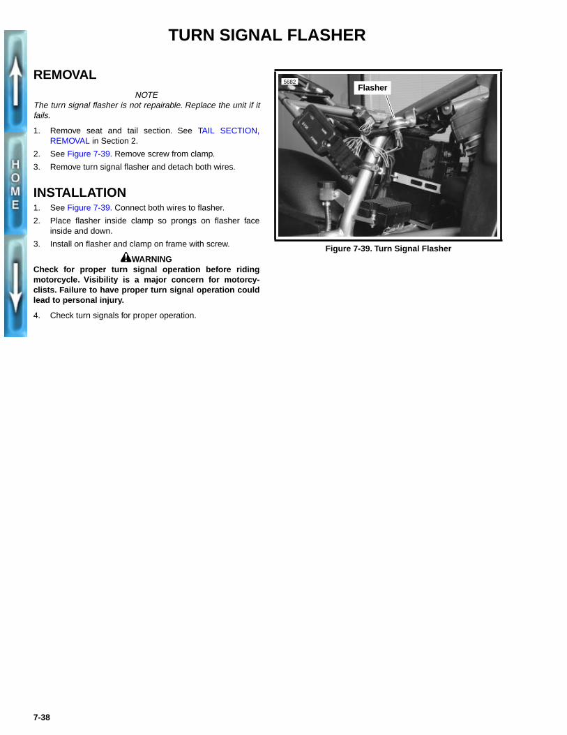
REMOVALNOTE
The turn signal flasher is not repairable. Replace the unit if itfails.
1. Remove seat and tail section. See TAIL SECTION,REMOVAL in Section 2.
2. See Figure 7-39. Remove screw from clamp.
3. Remove turn signal flasher and detach both wires.
INSTALLATION1. See Figure 7-39. Connect both wires to flasher.
2. Place flasher inside clamp so prongs on flasher faceinside and down.
3. Install on flasher and clamp on frame with screw.
1WARNINGCheck for proper turn signal operation before ridingmotorcycle. Visibility is a major concern for motorcy-clists. Failure to have proper turn signal operation couldlead to personal injury.
4. Check turn signals for proper operation.
Figure 7-39. Turn Signal Flasher
5682Flasher
7-38
HANDLEBAR SWITCHES
REMOVALNOTE
The individual handlebar switches are not repairable. Replacethe switch assembly upon switch failure.
Right Side1. See Steps 1-5 of THROTTLE CONTROL, REMOVAL/
DISASSEMBLY in Section 2.
2. Remove seat and fuel tank. See FUEL TANK, REMOVALin Section 4.
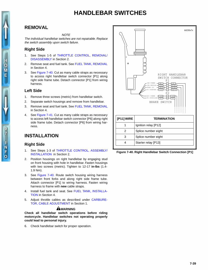
3. See Figure 7-40. Cut as many cable straps as necessaryto access right handlebar switch connector [P1] alongright side frame tube. Detach connector [P1] from wiringharness.
Left Side1. Remove three screws (metric) from handlebar switch.
2. Separate switch housings and remove from handlebar.
3. Remove seat and fuel tank. See FUEL TANK, REMOVALin Section 4.
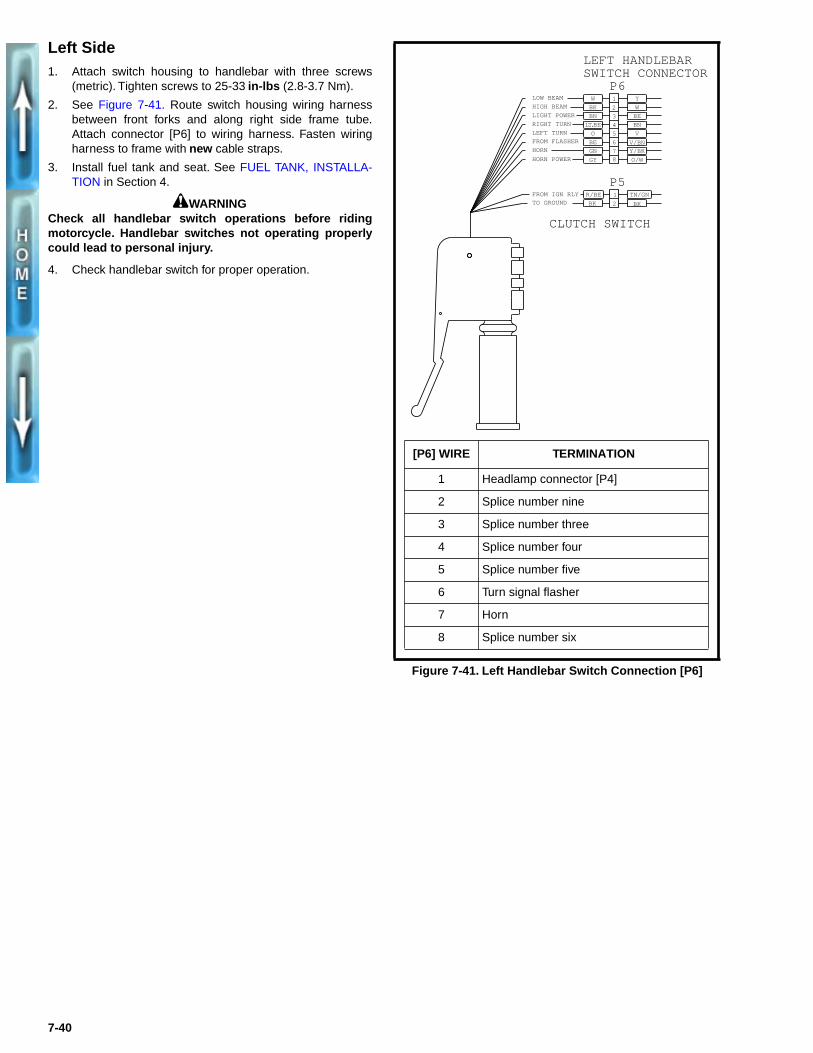
4. See Figure 7-41. Cut as many cable straps as necessaryto access left handlebar switch connector [P6] along rightside frame tube. Detach connector [P6] from wiring har-ness.
INSTALLATION
Right Side1. See Steps 1-3 of THROTTLE CONTROL, ASSEMBLY/
INSTALLATION in Section 2.
2. Position housings on right handlebar by engaging studon front housing with hole in handlebar. Fasten housingswith two screws (metric). Tighten to 12-17 in-lbs (1.4-1.9 Nm).
3. See Figure 7-40. Route switch housing wiring harnessbetween front forks and along right side frame tube.Attach connector [P1] to wiring harness. Fasten wiringharness to frame with new cable straps.
4. Install fuel tank and seat. See FUEL TANK, INSTALLA-TION in Section 4.
5. Adjust throttle cables as described under CARBURE-TOR, CABLE ADJUSTMENT in Section 1.
1WARNINGCheck all handlebar switch operations before ridingmotorcycle. Handlebar switches not operating properlycould lead to personal injury.
6. Check handlebar switch for proper operation.
Figure 7-40. Right Handlebar Switch Connection [P1]
GY
W/BK
W/BK
BK/R4
2
3
1
GN/BK
W/R
BE
Y/O
P1
P2
BRAKE SWITCH
RIGHT HANDLEBAR SWITCH CONNECTOR
1
2
O/WO/W
R/YR/YTO STOPLIGHTACC POWER
IGN MODULE
FROM (2)
TO STARTER
IGN POWER
[P11] WIRE TERMINATION
1 Ignition relay [P12]
2 Splice number eight
3 Splice number eight
4 Starter relay [P13]
b0235x7x
7-39
Left Side1. Attach switch housing to handlebar with three screws
(metric). Tighten screws to 25-33 in-lbs (2.8-3.7 Nm).
2. See Figure 7-41. Route switch housing wiring harnessbetween front forks and along right side frame tube.Attach connector [P6] to wiring harness. Fasten wiringharness to frame with new cable straps.
3. Install fuel tank and seat. See FUEL TANK, INSTALLA-TION in Section 4.
1WARNINGCheck all handlebar switch operations before ridingmotorcycle. Handlebar switches not operating properlycould lead to personal injury.
4. Check handlebar switch for proper operation.
Figure 7-41. Left Handlebar Switch Connection [P6]
BK
1
2BK
TN/GNR/BE
P6
P5
CLUTCH SWITCH
LEFT HANDLEBAR SWITCH CONNECTOR
LOW BEAM
HIGH BEAM
RIGHT TURN
LIGHT POWER
LEFT TURN
FROM FLASHER
HORN POWER
HORN
TO GROUNDFROM IGN RLY
1
3
4
5
6
78
2 W
Y
O/W
Y/BK
V
BN
BE
W
BK
BN
LT.BE
O
BE
GN
GY
V/BN
[P6] WIRE TERMINATION
1 Headlamp connector [P4]
2 Splice number nine
3 Splice number three
4 Splice number four
5 Splice number five
6 Turn signal flasher
7 Horn
8 Splice number six
7-40
HORN
REMOVAL1. Remove ignition coil to detach horn bracket from frame.
See IGNITION COIL, REMOVAL on page 7-17.
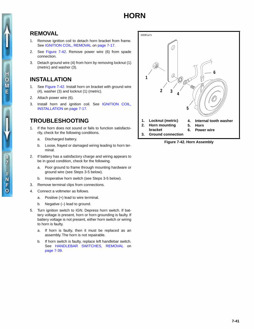
2. See Figure 7-42. Remove power wire (6) from spadeconnection.
3. Detach ground wire (4) from horn by removing locknut (1)(metric) and washer (3).
INSTALLATION1. See Figure 7-42. Install horn on bracket with ground wire
(4), washer (3) and locknut (1) (metric).
2. Attach power wire (6).
3. Install horn and ignition coil. See IGNITION COIL,INSTALLATION on page 7-17.
TROUBLESHOOTING1. If the horn does not sound or fails to function satisfacto-
rily, check for the following conditions.
a. Discharged battery.
b. Loose, frayed or damaged wiring leading to horn ter-minal.
2. If battery has a satisfactory charge and wiring appears tobe in good condition, check for the following.
a. Poor ground to frame through mounting hardware orground wire (see Steps 3-5 below).
b. Inoperative horn switch (see Steps 3-5 below).
3. Remove terminal clips from connections.
4. Connect a voltmeter as follows.
a. Positive (+) lead to wire terminal.
b. Negative (–) lead to ground.
5. Turn ignition switch to IGN. Depress horn switch. If bat-tery voltage is present, horn or horn grounding is faulty. Ifbattery voltage is not present, either horn switch or wiringto horn is faulty.
a. If horn is faulty, then it must be replaced as anassembly. The horn is not repairable.
b. If horn switch is faulty, replace left handlebar switch.See HANDLEBAR SWITCHES, REMOVAL onpage 7-39.
Figure 7-42. Horn Assembly
1. Locknut (metric)2. Horn mounting
bracket3. Ground connection
4. Internal tooth washer5. Horn6. Power wire
b0081a7x
1
2 3
5
4
6
7-41
NEUTRAL INDICATOR SWITCH
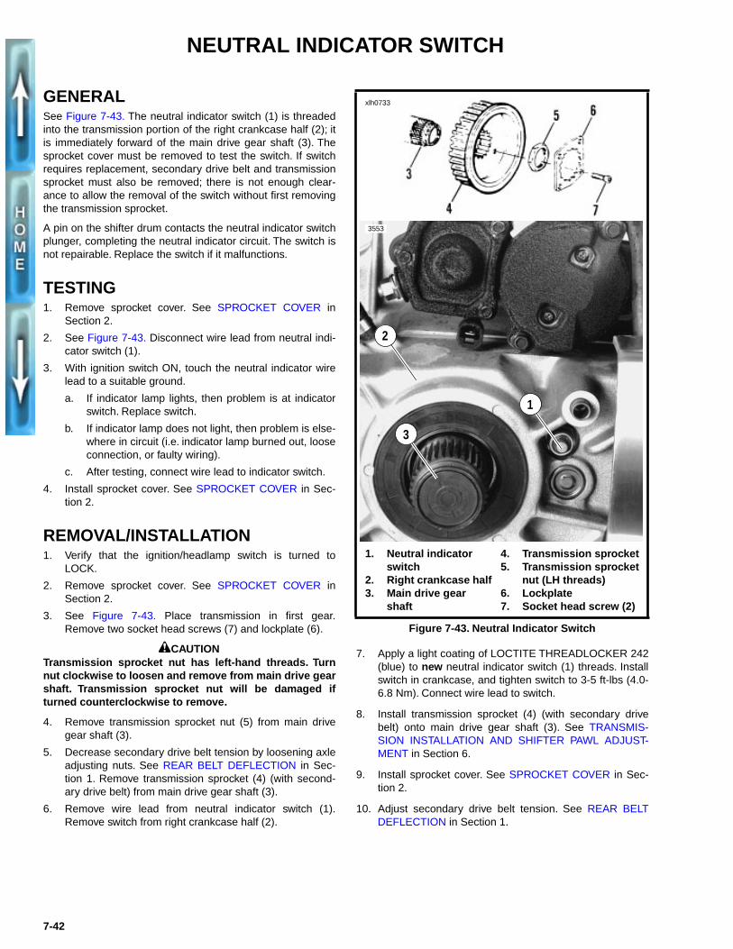
GENERALSee Figure 7-43. The neutral indicator switch (1) is threadedinto the transmission portion of the right crankcase half (2); itis immediately forward of the main drive gear shaft (3). Thesprocket cover must be removed to test the switch. If switchrequires replacement, secondary drive belt and transmissionsprocket must also be removed; there is not enough clear-ance to allow the removal of the switch without first removingthe transmission sprocket.
A pin on the shifter drum contacts the neutral indicator switchplunger, completing the neutral indicator circuit. The switch isnot repairable. Replace the switch if it malfunctions.
TESTING1. Remove sprocket cover. See SPROCKET COVER in
Section 2.
2. See Figure 7-43. Disconnect wire lead from neutral indi-cator switch (1).
3. With ignition switch ON, touch the neutral indicator wirelead to a suitable ground.
a. If indicator lamp lights, then problem is at indicatorswitch. Replace switch.
b. If indicator lamp does not light, then problem is else-where in circuit (i.e. indicator lamp burned out, looseconnection, or faulty wiring).
c. After testing, connect wire lead to indicator switch.
4. Install sprocket cover. See SPROCKET COVER in Sec-tion 2.
REMOVAL/INSTALLATION1. Verify that the ignition/headlamp switch is turned to
LOCK.
2. Remove sprocket cover. See SPROCKET COVER inSection 2.
3. See Figure 7-43. Place transmission in first gear.Remove two socket head screws (7) and lockplate (6).
1CAUTIONTransmission sprocket nut has left-hand threads. Turnnut clockwise to loosen and remove from main drive gearshaft. Transmission sprocket nut will be damaged ifturned counterclockwise to remove.
4. Remove transmission sprocket nut (5) from main drivegear shaft (3).
5. Decrease secondary drive belt tension by loosening axleadjusting nuts. See REAR BELT DEFLECTION in Sec-tion 1. Remove transmission sprocket (4) (with second-ary drive belt) from main drive gear shaft (3).
6. Remove wire lead from neutral indicator switch (1).Remove switch from right crankcase half (2).
7. Apply a light coating of LOCTITE THREADLOCKER 242(blue) to new neutral indicator switch (1) threads. Installswitch in crankcase, and tighten switch to 3-5 ft-lbs (4.0-6.8 Nm). Connect wire lead to switch.
8. Install transmission sprocket (4) (with secondary drivebelt) onto main drive gear shaft (3). See TRANSMIS-SION INSTALLATION AND SHIFTER PAWL ADJUST-MENT in Section 6.
9. Install sprocket cover. See SPROCKET COVER in Sec-tion 2.
10. Adjust secondary drive belt tension. See REAR BELTDEFLECTION in Section 1.
Figure 7-43. Neutral Indicator Switch
1. Neutral indicator switch
2. Right crankcase half3. Main drive gear
shaft
xlh0733
3
3553
1
2
4. Transmission sprocket5. Transmission sprocket
nut (LH threads)6. Lockplate7. Socket head screw (2)
7-42
FUSES AND CIRCUIT BREAKERS
GENERALThe S1 Lightning features two components which protect theelectrical system.
1WARNING
To avoid accidental start-up of vehicle and possiblepersonal injury, disconnect the battery cables beforeservicing motorcycle. Always disconnect the negativecable first. If the positive cable should contact groundwith the negative cable installed, the resulting sparksmay cause a battery explosion producing personal injury.
Fuses
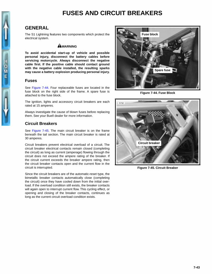
See Figure 7-44. Four replaceable fuses are located in thefuse block on the right side of the frame. A spare fuse isattached to the fuse block.
The ignition, lights and accessory circuit breakers are eachrated at 15 amperes.
Always investigate the cause of blown fuses before replacingthem. See your Buell dealer for more information.
Circuit Breakers
See Figure 7-45. The main circuit breaker is on the framebeneath the tail section. The main circuit breaker is rated at30 amperes.
Circuit breakers prevent electrical overload of a circuit. Thecircuit breaker electrical contacts remain closed (completingthe circuit) as long as current (amperage) flowing through thecircuit does not exceed the ampere rating of the breaker. Ifthe circuit current exceeds the breaker ampere rating, thenthe circuit breaker contacts open and the current flow in thecircuit is interrupted.
Since the circuit breakers are of the automatic-reset type, thebimetallic breaker contacts automatically close (completingthe circuit) once they have cooled down from the initial over-load. If the overload condition still exists, the breaker contactswill again open to interrupt current flow. This cycling effect, oropening and closing of the breaker contacts, continues aslong as the current circuit overload condition exists.
Figure 7-44. Fuse Block
Figure 7-45. Circuit Breaker
5682
Fuse block
Spare fuse
5732
Circuit breaker
7-43
ELECTRICAL CONNECTORS
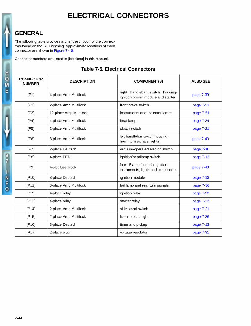
GENERALThe following table provides a brief description of the connec-tors found on the S1 Lightning. Approximate locations of eachconnector are shown in Figure 7-46.
Connector numbers are listed in [brackets] in this manual.
Table 7-5. Electrical Connectors
CONNECTORNUMBER
DESCRIPTION COMPONENT(S) ALSO SEE
[P1] 4-place Amp Multilockright handlebar switch housing-ignition power, module and starter
page 7-39
[P2] 2-place Amp Multilock front brake switch page 7-51
[P3] 12-place Amp Multilock instruments and indicator lamps page 7-51
[P4] 4-place Amp Multilock headlamp page 7-34
[P5] 2-place Amp Multilock clutch switch page 7-21
[P6] 8-place Amp Multilockleft handlebar switch housing-horn, turn signals, lights
page 7-40
[P7] 2-place Deutsch vacuum-operated electric switch page 7-10
[P8] 4-place PED ignition/headlamp switch page 7-12
[P9] 4-slot fuse blockfour 15 amp fuses for ignition,instruments, lights and accessories
page 7-43
[P10] 8-place Deutsch ignition module page 7-13
[P11] 8-place Amp Multilock tail lamp and rear turn signals page 7-36
[P12] 4-place relay ignition relay page 7-22
[P13] 4-place relay starter relay page 7-22
[P14] 2-place Amp Multilock side stand switch page 7-21
[P15] 2-place Amp Multilock license plate light page 7-36
[P16] 3-place Deutsch timer and pickup page 7-13
[P17] 2-place plug voltage regulator page 7-31
7-44
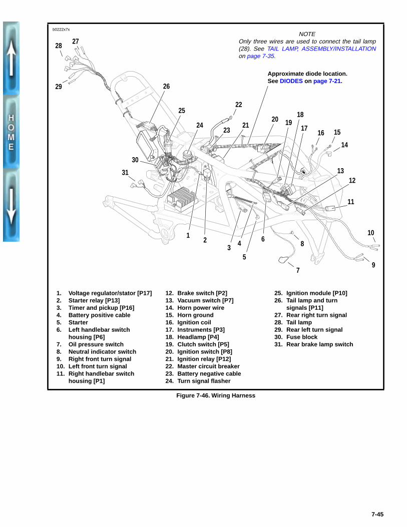
Figure 7-46. Wiring Harness
1. Voltage regulator/stator [P17]2. Starter relay [P13]3. Timer and pickup [P16]4. Battery positive cable5. Starter 6. Left handlebar switch
housing [P6]7. Oil pressure switch8. Neutral indicator switch9. Right front turn signal10. Left front turn signal11. Right handlebar switch
housing [P1]
12. Brake switch [P2]13. Vacuum switch [P7]14. Horn power wire15. Horn ground16. Ignition coil17. Instruments [P3]18. Headlamp [P4]19. Clutch switch [P5]20. Ignition switch [P8]21. Ignition relay [P12]22. Master circuit breaker23. Battery negative cable24. Turn signal flasher
25. Ignition module [P10]26. Tail lamp and turn
signals [P11]27. Rear right turn signal28. Tail lamp29. Rear left turn signal30. Fuse block31. Rear brake lamp switch
3 4
5
8
79
10
14
1516
1213
11
2021
22
23 1719
18
6
31
25
26
30
29
2728
12
24
NOTEOnly three wires are used to connect the tail lamp(28). See TAIL LAMP, ASSEMBLY/INSTALLATIONon page 7-35.
b0222x7x
Approximate diode location. See DIODES on page 7-21.
7-45
DEUTSCH ELECTRICAL CONNECTORS
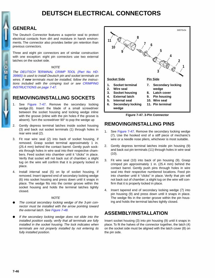
GENERALThe Deutsch Connector features a superior seal to protectelectrical contacts from dirt and moisture in harsh environ-ments. The connector also provides better pin retention thanprevious connectors.
Three and eight pin connectors are of similar constructionwith one exception: eight pin connectors use two externallatches on the socket side.
NOTE
The DEUTSCH TERMINAL CRIMP TOOL (Part No. HD-39965) is used to install Deutsch pin and socket terminals onwires. If new terminals must be installed, follow the instruc-tions included with the crimping tool or see CRIMPINGINSTRUCTIONS on page 7-47.
REMOVING/INSTALLING SOCKETS1. See Figure 7-47. Remove the secondary locking
wedge (6). Insert the blade of a small screwdriverbetween the socket housing and locking wedge inlinewith the groove (inline with the pin holes if the groove isabsent). Turn the screwdriver 90° to pop the wedge up
2. Gently depress terminal latches inside socket housing(3) and back out socket terminals (1) through holes inrear wire seal (2).
3. Fit rear wire seal (2) into back of socket housing, ifremoved. Grasp socket terminal approximately 1 in.(25.4 mm) behind the contact barrel. Gently push sock-ets through holes in wire seal into their respective cham-bers. Feed socket into chamber until it “clicks” in place.Verify that socket will not back out of chamber; a slighttug on the wire will confirm that it is properly locked inplace.
4. Install internal seal (5) on lip of socket housing, ifremoved. Insert tapered end of secondary locking wedge(6) into socket housing and press down until it snaps inplace. The wedge fits into the center groove within thesocket housing and holds the terminal latches tightlyclosed.
NOTE
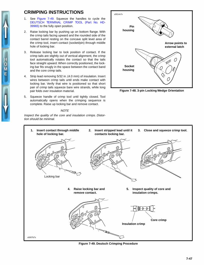
● The conical secondary locking wedge of the 3-pin con-nector must be installed with the arrow pointing towardthe external latch. See Figure 7-48.
● If the secondary locking wedge does not slide into theinstalled position easily, verify that all terminals are fullyinstalled in the socket housing. The lock indicates whenterminals are not properly installed by not entering itsfully installed position.
REMOVING/INSTALLING PINS1. See Figure 7-47. Remove the secondary locking wedge
(7). Use the hooked end of a stiff piece of mechanic’swire or a needle nose pliers, whichever is most suitable.
2. Gently depress terminal latches inside pin housing (9)and back out pin terminals (11) through holes in wire seal(10).
3. Fit wire seal (10) into back of pin housing (9). Graspcrimped pin approximately 1 in. (25.4 mm) behind thecontact barrel. Gently push pins through holes in wireseal into their respective numbered locations. Feed pininto chamber until it “clicks” in place. Verify that pin willnot back out of chamber; a slight tug on the wire will con-firm that it is properly locked in place.
4. Insert tapered end of secondary locking wedge (7) intopin housing (9) and press down until it snaps in place.The wedge fits in the center groove within the pin hous-ing and holds the terminal latches tightly closed.
ASSEMBLY/INSTALLATIONInsert socket housing (3) into pin housing (9) until it snaps inplace. To fit the halves of the connector together, the latch (4)on the socket side must be aligned with the latch cover (8) onthe pin side.
Figure 7-47. 3-Pin Connector
11
109
8
7 6
54
3
21
b0070x3x
Pin Side
7. Secondary locking wedge
8. Latch cover9. Pin housing10. Wire seal11. Pin terminal
Socket Side
1. Socket terminal2. Wire seal3. Socket housing4. External latch5. Internal seal6. Secondary locking
wedge
7-46
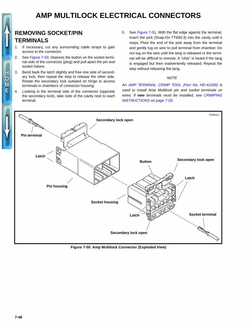
CRIMPING INSTRUCTIONS1. See Figure 7-49. Squeeze the handles to cycle the
DEUTSCH TERMINAL CRIMP TOOL (Part No. HD-39965) to the fully open position.
2. Raise locking bar by pushing up on bottom flange. Withthe crimp tails facing upward and the rounded side of thecontact barrel resting on the concave split level area ofthe crimp tool, insert contact (socket/pin) through middlehole of locking bar.
3. Release locking bar to lock position of contact. If thecrimp tails are slightly out of vertical alignment, the crimptool automatically rotates the contact so that the tailsface straight upward. When correctly positioned, the lock-ing bar fits snugly in the space between the contact bandand the core crimp tails.
4. Strip lead removing 5/32 in. (4.0 mm) of insulation. Insertwires between crimp tails until ends make contact withlocking bar. Verify that wire is positioned so that shortpair of crimp tails squeeze bare wire strands, while longpair folds over insulation material.
5. Squeeze handle of crimp tool until tightly closed. Toolautomatically opens when the crimping sequence iscomplete. Raise up locking bar and remove contact.
NOTE
Inspect the quality of the core and insulation crimps. Distor-tion should be minimal.
Figure 7-48. 3-pin Locking Wedge Orientation
x0014x7x
Sockethousing
Pinhousing
Arrow points to external latch
Figure 7-49. Deutsch Crimping Procedure
1. Insert contact through middle hole of locking bar.
2. Insert stripped lead until it contacts locking bar.
3. Close and squeeze crimp tool.
4. Raise locking bar and remove contact.
5. Inspect quality of core and insulation crimps.
x0007b7x
Locking bar
Insulation crimpCore crimp
7-47
AMP MULTILOCK ELECTRICAL CONNECTORS
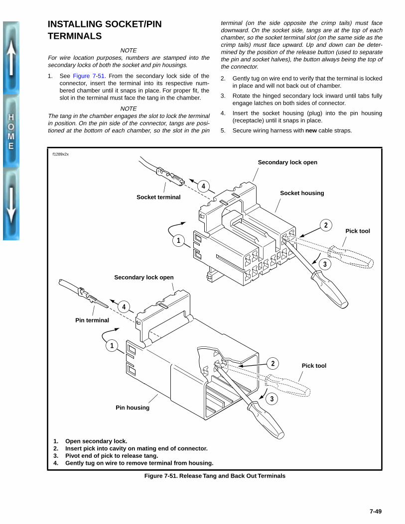
REMOVING SOCKET/PINTERMINALS1. If necessary, cut any surrounding cable straps to gain
access to the connector.
2. See Figure 7-50. Depress the button on the socket termi-nal side of the connector (plug) and pull apart the pin andsocket halves.
3. Bend back the latch slightly and free one side of second-ary lock, then repeat the step to release the other side.Rotate the secondary lock outward on hinge to accessterminals in chambers of connector housing.
4. Looking in the terminal side of the connector (oppositethe secondary lock), take note of the cavity next to eachterminal.
5. See Figure 7-51. With the flat edge against the terminal,insert the pick (Snap-On TT600-3) into the cavity until itstops. Pivot the end of the pick away from the terminaland gently tug on wire to pull terminal from chamber. Donot tug on the wire until the tang is released or the termi-nal will be difficult to remove. A “click” is heard if the tangis engaged but then inadvertently released. Repeat thestep without releasing the tang.
NOTE
An AMP TERMINAL CRIMP TOOL (Part No. HD-41609) isused to install Amp Multilock pin and socket terminals onwires. If new terminals must be installed, see CRIMPINGINSTRUCTIONS on page 7-50.
Figure 7-50. Amp Multilock Connector (Exploded View)
Pin terminal
Latch
Pin housing
Socket housing
Secondary lock open
Secondary lock open
Latch
Latch
Button
Secondary lock open
Socket terminal
f1292x2x
7-48
INSTALLING SOCKET/PIN TERMINALS
NOTEFor wire location purposes, numbers are stamped into thesecondary locks of both the socket and pin housings.
1. See Figure 7-51. From the secondary lock side of theconnector, insert the terminal into its respective num-bered chamber until it snaps in place. For proper fit, theslot in the terminal must face the tang in the chamber.
NOTEThe tang in the chamber engages the slot to lock the terminalin position. On the pin side of the connector, tangs are posi-tioned at the bottom of each chamber, so the slot in the pin
terminal (on the side opposite the crimp tails) must facedownward. On the socket side, tangs are at the top of eachchamber, so the socket terminal slot (on the same side as thecrimp tails) must face upward. Up and down can be deter-mined by the position of the release button (used to separatethe pin and socket halves), the button always being the top ofthe connector.
2. Gently tug on wire end to verify that the terminal is lockedin place and will not back out of chamber.
3. Rotate the hinged secondary lock inward until tabs fullyengage latches on both sides of connector.
4. Insert the socket housing (plug) into the pin housing(receptacle) until it snaps in place.
5. Secure wiring harness with new cable straps.
Figure 7-51. Release Tang and Back Out Terminals
Pin terminal
Pin housing
Secondary lock open
Secondary lock open
Pick tool
Socket terminalSocket housing
Pick tool
4
1
3
2
1
4
2
3
1. Open secondary lock.2. Insert pick into cavity on mating end of connector.3. Pivot end of pick to release tang.4. Gently tug on wire to remove terminal from housing.
f1289x2x
7-49
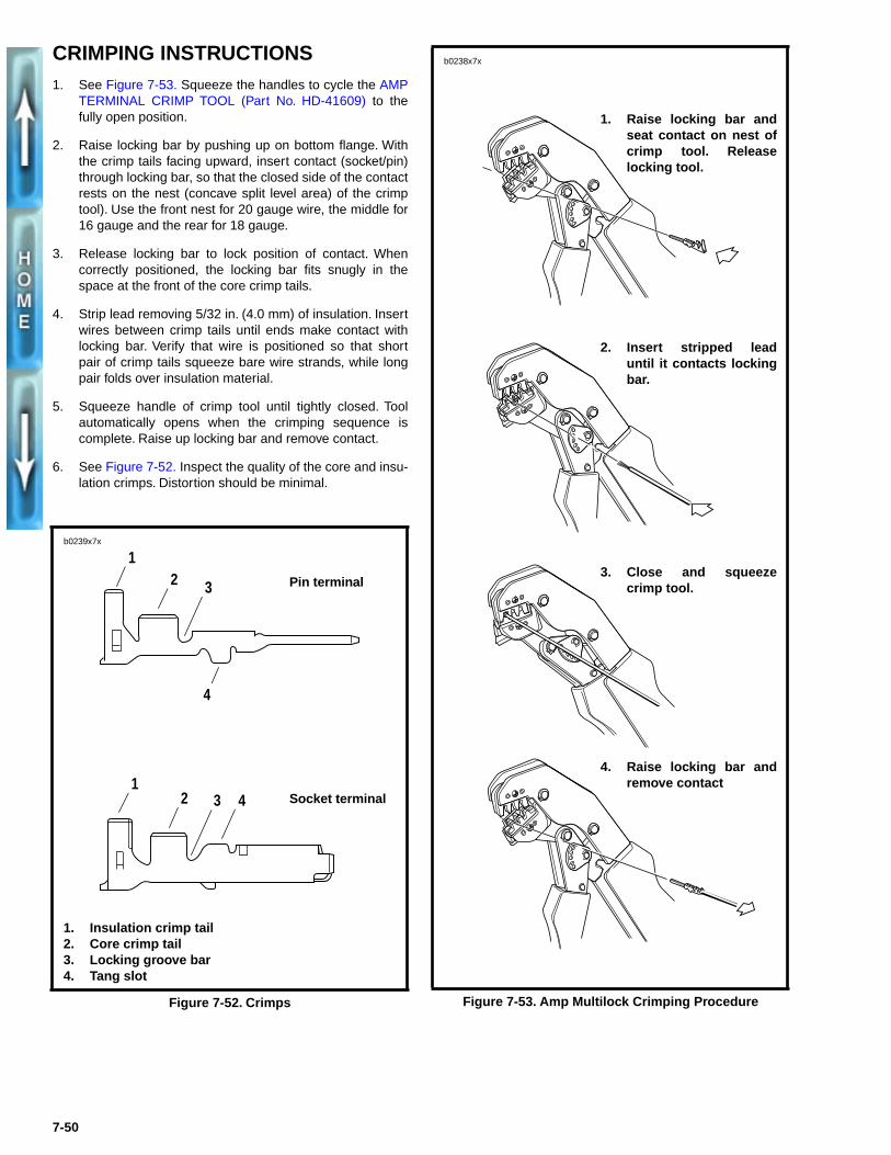
CRIMPING INSTRUCTIONS1. See Figure 7-53. Squeeze the handles to cycle the AMP
TERMINAL CRIMP TOOL (Part No. HD-41609) to thefully open position.
2. Raise locking bar by pushing up on bottom flange. Withthe crimp tails facing upward, insert contact (socket/pin)through locking bar, so that the closed side of the contactrests on the nest (concave split level area) of the crimptool). Use the front nest for 20 gauge wire, the middle for16 gauge and the rear for 18 gauge.
3. Release locking bar to lock position of contact. Whencorrectly positioned, the locking bar fits snugly in thespace at the front of the core crimp tails.
4. Strip lead removing 5/32 in. (4.0 mm) of insulation. Insertwires between crimp tails until ends make contact withlocking bar. Verify that wire is positioned so that shortpair of crimp tails squeeze bare wire strands, while longpair folds over insulation material.
5. Squeeze handle of crimp tool until tightly closed. Toolautomatically opens when the crimping sequence iscomplete. Raise up locking bar and remove contact.
6. See Figure 7-52. Inspect the quality of the core and insu-lation crimps. Distortion should be minimal.
Figure 7-52. Crimps
b0239x7x
12 3
4
12 3 4
Pin terminal
Socket terminal
1. Insulation crimp tail2. Core crimp tail3. Locking groove bar4. Tang slot
Figure 7-53. Amp Multilock Crimping Procedure
b0238x7x
1. Raise locking bar andseat contact on nest ofcrimp tool. Releaselocking tool.
2. Insert stripped leaduntil it contacts lockingbar.
3. Close and squeezecrimp tool.
4. Raise locking bar andremove contact
7-50
7-51
S2
3/28/96
BK
/BY K
GN/YTN
OIL PRESSURE
SWITCH NEUTRAL SWITCH
R/Y
R/Y
O/W
REAR STOPLIGHT SWITCH
TN/WBK
BK W
P14 12
SIDE STAND SWITCH
RIGHT REAR TURN SIGNAL
1
2
3
4
5
6
78
P11BK BK
BK
V
R/Y
BN
V
O/W
BK
BK
R/Y
V
BK
BK
1
2
1 2
P15BE BE Y
BK BK BK
LICENSE PLATE LIGHT
MAIN CHASSIS GROUND
R/Y
BKO/W
BE
R/BK
TAIL LAMP
LEFT REAR TURN SIGNAL
BEBK
LT.BE
30AMASTER CIRCUIT BREAKER
R
P17
BK
BK
BK
GN
VOLTAGE REGULATOR
BK
BK
BK
BK
STATORBATTERY
/BR K
/R GY
H
CK
OFF
N
BNO/W
BN
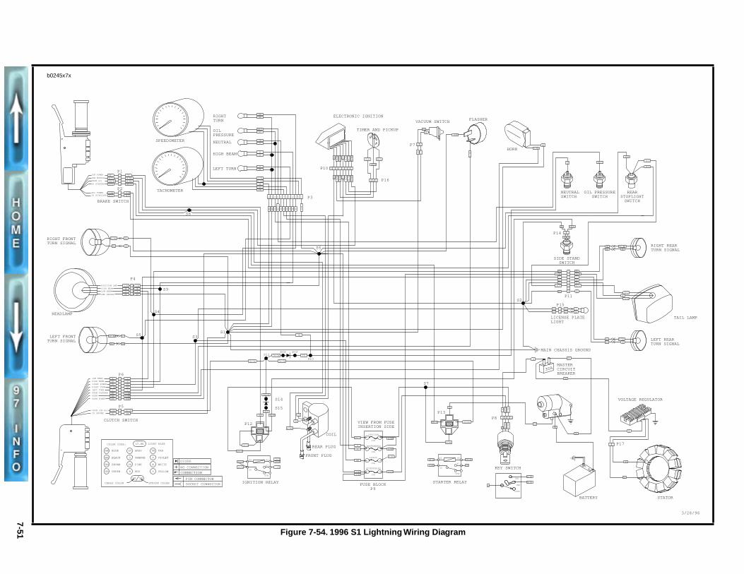
Figure 7-54. 1996 S1 Lightning Wiring Diagram
1996 BUELL S1-LIGHTNING WIRING DIAGRAM
S7
LEFT TURN
RIGHT TURN
HIGH BEAM
OIL PRESSURE
SPEEDOMETER
TACHOMETER
NEUTRAL
W
GN/Y
O
BK
V
BK
O
W/GN
BK
PK
BK
BN
O/W
O
TN
123456789101112
O OBK
BK V BNW
GN/Y
PK
TN
P10
P3
O/W
ELECTRONIC IGNITION
TIMER AND PICKUP
BK
PK
BK/W
GN/W
W/BK
R/W
V/W
12345678
BK
PK
BK/W
GN/W
W/BK
R/W
V/W
P16
/WGN
/WBK
CBA
R/W
P7
BK
BK
2 1
KB /W
V
FLASHERVACUUM SWITCH
O/W
V/BN
HORN
A B C DP8
/R
GY
/R
GY
/B
RK
R
/B
RR
K
R
KEY SWITC
LO
IG
85
30
BK/R
R/BK
86
87
87A
GN
TN/GN
STARTER RELAY
P13
BK/R
GN
R/BK
TN/GNVIEW FROM FUSE INSERTION SIDE
GY/O
BE
O/WO/W
O
O
R/BK
R/BK
R/BK
R/GY
INSTRUMENTS
15A
LIGHTS
15A
15A
ACCESSORIES
15A
IGNITION
FUSE BLOCK P9
REAR PLUG
FRONT PLUG
COIL
PK
PK
W/BK
85
30
86
87
87A
GY/O
GY/O
TN/WTN/W
GY
IGNITION RELAY
GY/O
GY/O
P12
S14
S15
TN/W
TN/W
TN/GN
GYBK
1
2BK
TN/GNR/BE
P6
P5
CLUTCH SWITCH
LOW BEAM
HIGH BEAM
RIGHT TURN
LIGHT POWER
LEFT TURN
FROM FLASHER
HORN POWER
HORN
TO GROUNDFROM IGN RLY
1
3
4
5
6
78
2 W
Y
O/W
Y/BK
V
BN
BE
W
BK
BN
LT BE
O
BE
GN
GY
V/BN
TN
TN/GN
TN/GN
TN/GN
S11
S10
S12S13
TNS3S1
S5
BKBE
VLT.BE
S9
S4
P4
W
BK
Y2
3
4
O/W1
BK
W
O/W
Y
POSITION LMP
HIGH BEAMLOW BEAM
LMP GROUND
HEADLAMP
LEFT FRONT TURN SIGNAL
RIGHT FRONT TURN SIGNAL
BNR/BK
KBBE
S8
GY
W/BK
W/BK
BK/R4
2
3
1
GN/BK
W/R
BE
Y/O
P1
P2
BRAKE SWITCH
1
2
O/WO/WR/YR/YTO STOPLIGHT
ACC POWER
IGN MODULE
FROM (2)
TO STARTER
IGN POWER
S6
LT.BE LIGHT BLUE
CABLE COLOR
BE
COLOR CODE:
BK
BN
GN
GY
O
BLUE
BLACK
BROWN
GREEN
GRAY
ORANGE
PINK
RED
TAN
VIOLET
WHITE
YELLOW
PK
R
TN
V
W
Y
STRIPE COLOR
XX XX PIN CONNECTOR
SOCKET CONNECTOR
NO CONNECTION
CONNECTION
DIODE
b0245x7x