Embed Size (px)
Citation preview

Dartmouth Magnetics and Power Electronics Research Group
1
Power Magnetics: Emerging Technologies and
Research Needs
Charles R. [email protected]
http://power.engineering.dartmouth.edu
power.thayer.dartmouth.edu 2
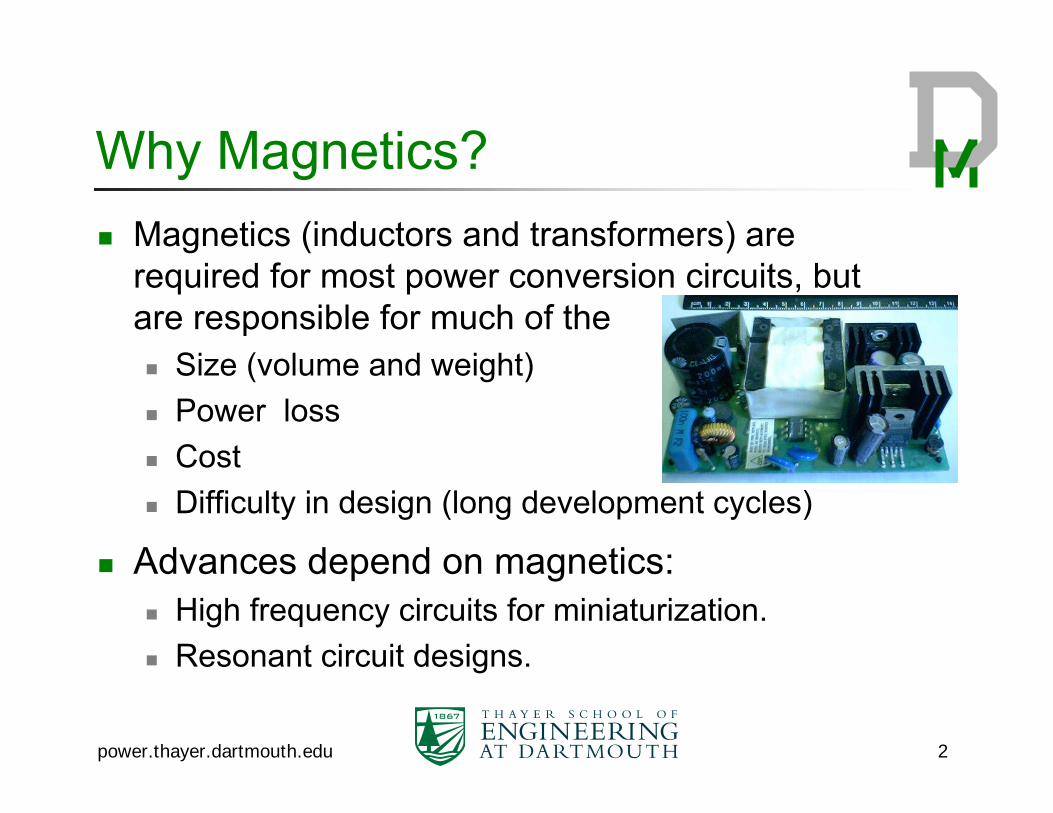
Why Magnetics?Magnetics (inductors and transformers) are required for most power conversion circuits, but are responsible for much of the
Size (volume and weight)Power lossCostDifficulty in design (long development cycles)
Advances depend on magnetics:High frequency circuits for miniaturization.Resonant circuit designs.
power.thayer.dartmouth.edu 3
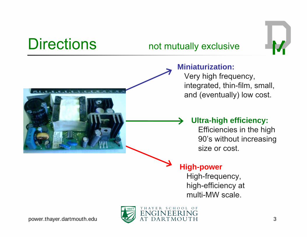
Directions not mutually exclusive
Miniaturization: Very high frequency, integrated, thin-film, small, and (eventually) low cost.
Ultra-high efficiency: Efficiencies in the high 90’s without increasing size or cost.
High-powerHigh-frequency, high-efficiency at multi-MW scale.

Minaturization
General idea: for given impedance Z = jωL, the inductance needed goes down with frequency.
Similar scaling for transformers.Actual scaling depends on material properties (with a magnetic core).
Examine “performance factor” B·f…..
power.thayer.dartmouth.edu 4

power.thayer.dartmouth.edu 5
Curves of B·fproduct for constant power loss density…No benefit from f > ~ 1 MHz.Need differentmaterials for higher frequency.
“Performance factor” for MnZn power ferrites
100 kHz 1 MHz
plotted for 300 mW/cm3
20 kHz·T
30 kHz·T
200 mT
40 mT

power.thayer.dartmouth.edu 6
Air-core vs. magnetic core
“Air core”is really any non-magnetic, dielectric material.
coil coil Magnetic Core: soft
magneticmaterial
with relativepermeability
μr >> 1
(B = μr·μ0·H)
Magnetic core increases L (inductance) by a factor μr,typ. 4 ~10,000Allows smaller volume, fewer turns for same L

power.thayer.dartmouth.edu 7
The case for air-coreAt very high frequencies (e.g. VHF = 30 MHz to 300 MHz), the inductance value is small and readily achievable without magnetic materials.Always gets better at higher frequency:At constant η (constant Q): Volume proportional to f -3/2
At constant heat flux: Volume proportional to f -1/2
with Q improving as f 1/3
Avoid magnetic material disadvantages:Power losses due to hysteresis and eddy currents.Frequency limitations: any material gets too lossy above some frequency, often only a few MHz.Not available in standard IC or packaging processes.

power.thayer.dartmouth.edu 8
Air-core challengesLow permeability leads to low flux density, which requires substantial volume for sufficient flux.Requires more turns → more winding loss.Flux is not contained by a core; external flux can cause EMI problems and eddy-current loss in nearby conductors.Requires significant air volume.
power.thayer.dartmouth.edu 9
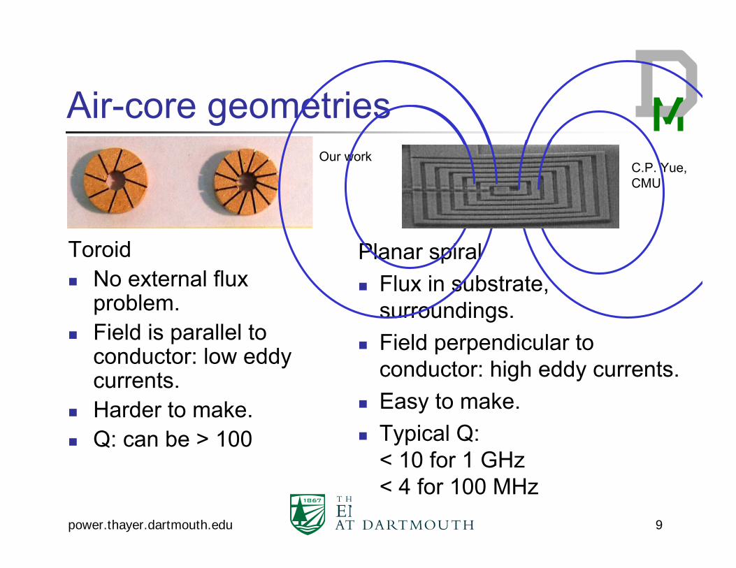
Air-core geometries
ToroidNo external flux problem.Field is parallel to conductor: low eddy currents.Harder to make.Q: can be > 100
Planar spiralFlux in substrate, surroundings.Field perpendicular to conductor: high eddy currents.Easy to make.Typical Q: < 10 for 1 GHz< 4 for 100 MHz
Our workC.P. Yue, CMU

power.thayer.dartmouth.edu 10
Air-core performance limitsField between two layers of copper (e.g. large-footprint toroid)
Can do better with multilayer copper (in theory): improve by a factor
where p is number of copper layers. Requires height for flux path!Packaging layer vs. on-chip.
300 MHzMax
imum
Q
1
10
100
100 MHz 30 MHz
Height
10 μm 100 μm 1 mm
p

power.thayer.dartmouth.edu 11
Magnetic material options
MnZn Ferrites: MS = 0.45 T, but losses limit BAC to 50 mT at f ~1 MHzRF materials: NiZn, powdered iron: 10’s of MHz, but still only 10’s of mT: need thick cores for power.Many thin-film materials: MS = 1~2 T, can operate with full flux swing, up to 10’s of MHz to 1 GHz.
Power density ~ B·f ⇒ 103 to 104 X improvement.
Option for aggressive miniaturization
power.thayer.dartmouth.edu 12
Thin-film magnetic materials
Typically alloys with Fe, Co and or Ni.Sputtered or electroplated.Relative permeability μr in the 100’s or 1000’s.Resistivity ~ 20 – 600 μΩ·cm;
High end preferred for low eddy-current lossMay still need laminations.
Hysteresis loss?

power.thayer.dartmouth.edu 13
Magnetic anisotropy
-200 -100 0 100 200-1.5
-1.0
-0.5
0.0
0.5
1.0
1.5
M (T
)
Field (Oe)
Easy Axis
Hard Axis:Near-perfect lossless loop
Hard axis loop provides:Low permeability needed to avoid saturation in inductors.Low hysteresis loss.

power.thayer.dartmouth.edu 14
Nano-composite magnetic materials
Advantages:Ferromagnetic (coupled particles)High resistivity (300 ~ 600 μΩ·cm) controls eddy-current loss independent of flux direction.Some have strong anisotropy for low permeability and low hysteresis loss.
Magnetic Metal
Ceramic
(3~5 nm CoParticles)
(Al2O3, ZrO2, etc.)

power.thayer.dartmouth.edu 15
Permeabilty vs. frequency
0.1
1
10
100
1000
1 10 100 1000 10000Frequency ( MHz )
Perm
eabi
lity
cμ ′′
cμ′
μ ′′
μ′
Q = 370 Q = 37

power.thayer.dartmouth.edu 16
CoOSi
TEM of multilayer nanogranular film
100 nm
HRTEM11
ZrOxSiO
x
Si (001)
ZrOx
ZrOx
Co-ZrOX
High
Res
olut
ion
TEM
Co-ZrOX

power.thayer.dartmouth.edu 17
V-Groove Inductor Design
One-turn inductor for high-current low-voltage microprocessor power supply.Easy fabrication process
Silicon wafer
Conductor(Cu)
Moderatepermeability
magnetic material

power.thayer.dartmouth.edu 18
Silicon
Copper
8-μm-thick390 μm
550 μm
Co-Zr-O
Cross-Section of V-Groove Inductors
10-μm-thickCo-Zr-O

power.thayer.dartmouth.edu 19
Miniaturization research needsMagnetic materials development.Understand, measure, and model power losses in materials.Fabrication processes for miniaturized inductors and transformers.Electromagnetic design for low losses.
High-frequency windings, application of anisotropic magnetic materials…
Co-design of circuits and magnetic components.
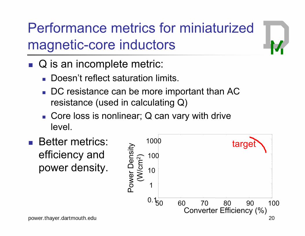
Q is an incomplete metric:Doesn’t reflect saturation limits.DC resistance can be more important than AC resistance (used in calculating Q)Core loss is nonlinear; Q can vary with drive level.
Better metrics: efficiency and power density.
Converter Efficiency (%)
Pow
er D
ensi
ty
(W/c
m2 )
50 60 70 80 90 1000.1
1
10
100
1000 target
power.thayer.dartmouth.edu 20
Performance metrics for miniaturized magnetic-core inductors

power.thayer.dartmouth.edu 21
Ultra-high efficiencyMiniaturization:
Very high frequency, integrated, thin-film, small, and (eventually) low cost.
Ultra-high efficiency: Efficiencies in the high 90’s without increasing size or cost.
High-powerHigh-frequency, high-efficiency at multi-MW scale.

Ultra-high efficiency
Accurate loss models are essential:Understand all sources of loss.Optimize to get ultra-high efficiency without high cost.
Co-design with circuits.Materials
Better MnZn ferrite materials?Bulk nanocomposite materials?
power.thayer.dartmouth.edu 22

Loss models for ultra-high efficiency
Core loss:Effect of non-sinusoidal waveforms on loss in ferrites.Effect of dc bias on loss in ferrites.
Winding loss:Tradeoff between ac and dc winding loss.Practical models for complex winding approaches.
power.thayer.dartmouth.edu 23

power.thayer.dartmouth.edu 24
High PowerMiniaturization:
Very high frequency, integrated, thin-film, small, and (eventually) low cost.
Ultra-high efficiency: Efficiencies in the high 90’s without increasing size or cost.
High-powerHigh-frequency, high-efficiency at multi-MW scale.

High-power characteristics
Large size makes two particular challenges severe:
Overall winding size is large compared to skin depth. 10 cm scale at 10 kHz has the same ratio (150) as mm scale for 100 MHz.Thermal management—low surface-area to volume ratio.
Magnetic Materials: Amorphous, nanocrystalline, steel.
power.thayer.dartmouth.edu 25

High-power research needs
Magnetic material improvements (amorphous, nanocrystalline, steel).Core loss modeling with nonsinusoidal waveforms.Winding designs:
For severe size-to-skin-depth ratios.For mixed-frequency currents.
Co-design of magnetics and circuits
power.thayer.dartmouth.edu 26

power.thayer.dartmouth.edu 27
Highlights
Common Themes:Magnetic material development.Loss modeling and electromagnetic design.Co-design of circuit and magnetics.
Miniaturization: Air core and magnetic core.Nano-granular magnetic materials.
Ultra-high efficiency:Loss modeling and design optimization.
High power:Large size to skin-depth ratio.Thermal design essential.
CoOSi

power.thayer.dartmouth.edu 28
This recent tutorial/overview paper on integrating magnetics for on-chip power converters has 66 references including many I’d like to list here, plus more extensive discussion of air-core and magnetic-core miniaturized power magnetics:C.R. Sullivan, “Integrating Magnetics for On-Chip Power: Challenges and Opportunities,” Invited
paper. IEEE Custom Integrated Circuits Conference, Sept. 2009. This includes advanced modeling of losses in multilayer thin-film materials, and also introduces a modified performance factor for magnetic materials that is more appropriate for high-frequency designs:Di Yao and C.R. Sullivan, “Effect of Capacitance on Eddy-Current Loss in Multi-Layer Magnetic
Films for MHz Magnetic Components,” IEEE Energy Conversion Conference and Exposition, Sept. 2009.This forthcoming paper has measurements of losses in ferrites with non-sinusoidal waveforms that show phenomena not expected based on existing models:C.R. Sullivan, J.H. Harris, E. Herbert “Core Loss Predictions for General PWM Waveforms from
a Simplified Set of Measured Data,” IEEE Applied Power Electronics Conference, Feb. 25, 2010.This paper contains a high-level theoretical overview of the potential for reducing winding loss through advanced winding design, without reference to particular practical designs:M.E. Dale and C.R. Sullivan. “Comparison of Single-Layer and Multi-Layer Windings with
Physical Constraints or Strong Harmonics.” IEEE International Symposium on Industrial Electronics, July 2006.
Selected references

Additional Slides
power.thayer.dartmouth.edu 29

power.thayer.dartmouth.edu 30
Thin-film inductor designs
Fundamental requirement: link core and coil.Requires at least three deposition steps:
Magnetic, Conductor, Magnetic (MCM), orConductor, Magnetic, Conductor (CMC)
Or a magic trick….

power.thayer.dartmouth.edu 31
Designs linking core and coilMCM “pot-core” CMC “toroidal”
Steps: Mag., Cond., Mag. Cond., Mag., Cond
Plan
Cross-section

power.thayer.dartmouth.edu 32
MCM vs. CMC
Same efficiency
2X higher power density(see ref [48,51])
More expensive (less than 2X) if magnetic deposition is more expensive than copper depostion.
Lower power density(same copper thickness, same magnetic thickness.)
Need good via resistance.
Anisotropy orientation problem at ends
Lossy, orTwo magnetic deposition steps.
Tyndall

power.thayer.dartmouth.edu 33
The sandwich inductorStraightforwardconcept to improve planar spiral.Multiple problems:
Air gap (in magnetic path) positioned wrong for ac resistance:
Flux direction in anisotropic core.