Embed Size (px)
Citation preview

Chase Beatty (Team Leader)
Brian Martinez (Organizer)
Mohammed Ramadan (Financial Officer)
Noe Caro (Historian)
SAE AERO
Chase Beatty
CUSTOMER DESCRIPTION
• Dr. John Tester
• SAE advisor since 2000
• Judges at AERO competition
• Academic advisor
• Dr. Tom Acker
Chase Beatty

PROJECT DESCRIPTION• Design and build an airplane
• Combined dimensions cannot exceed 225”
• Take off within 200ft
• Land and stop within 400ft
• Payload and airplane cannot exceed 55lbs
• Fly in a circle at least once
• No lighter than air aircrafts or helicopters
Land Land within 400’ 0’
Takeoff within 200’ Brian Martinez
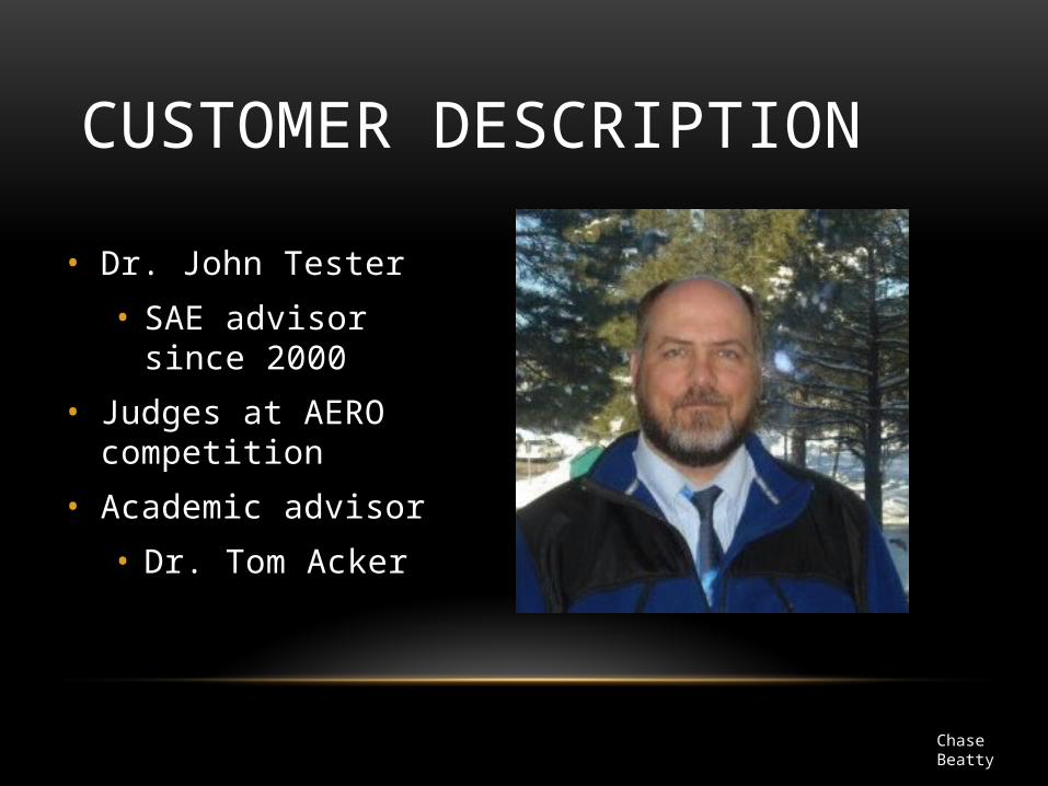
PROJECT DESCRIPTION CONT.
• Propeller cannot be made out of metal
• Fiber-Reinforced Plastic is prohibited
• No fuel pump
• Cannot used gear boxes—gear ratio
• Fuel supplied by competition
• No gyroscope
• Must raise our own funds
Brian Martinez

PROJECT SCHEDULE• Phase 1: Research
• 09/19/11 – 03/01/12
• Equations, materials and airplane design
• Phase 2: Fundraising
• 09/19/11 – 12/27/11
• Wing-a-thon
• Phase 3: Design the Prototype
• 10/17/11 – 12/18/11
• Solidworks model
Brian Martinez

PROJECT SCHEDULE CONT.• Phase 4: Construction of Final Aircraft
• 12/28/11 – 02/15/12
• Wing
• Fuselage
• Landing Gear
• Phase 5: Testing the Aircraft
• 02/16/12 – 03/07/12
• Performance analysis
• Phase 6: Competition
• 03/16/11 – 03/18/11
Brian Martinez

BUDGET
Estimated Budget (dollars)
Registration 600
Fuel Cost (Transportation) 450Hotel Cost (4 nights) 300Food/Drink Cost 600Balsa Wood 30Bass Wood 20Monokote 30O.S. 61FX 150Servos 50Receiver 100TOTAL 2330
Brian Martinez
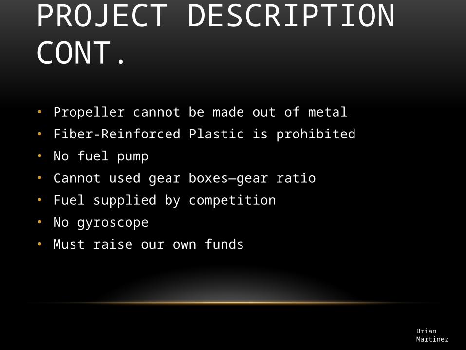
MAN POWER
Time Frame Hours per week per person Total hours per person
Fall (9/19-12/16) 8 104
Winter (12/19-1/13) 35 140
Spring (1/16-3/15) 20 180
Total Project Length 424
Chase Beatty

FUSELAGE DESIGN 1
• Balsa wood shell
• Balsa wood ribs inside
• Easy wing mounting
• Easy tail mounting
• Angled tail end
Chase Beatty

FUSELAGE DESIGN 2
• Monokote wrapped around ribs
• Hard to mount wings
• Lighter weight than Balsa shell
• Weaker fuselage
• Angled tail end
Chase Beatty

FUSELAGE DESIGN 3
• Combination of first two designs
• Solid balsa shell for easy wing mount
• Monokote for tail end for lighter weight
• Angled tail end
Chase Beatty

AERODYNAMICS ANALYSIS AIRFOIL RESEARCH
Research Previous teams selection
2010 – E 423
2009 – E 423
Common airfoil
E 423
Clark Y
Our selection for aerodynamics analysis and comparsion
E 423
Clark Y
Mohammed Ramadan

AIRFOIL KEY PARAMETERS
CL – Lift Coefficient , Cd – Drag Coefficient , Stall , α – Angle of Attack (AoA)
Lift to Drag Ratio
Mohammed Ramadan
Stall: is a sudden drop in the lift coefficient when reaching a critical AoA
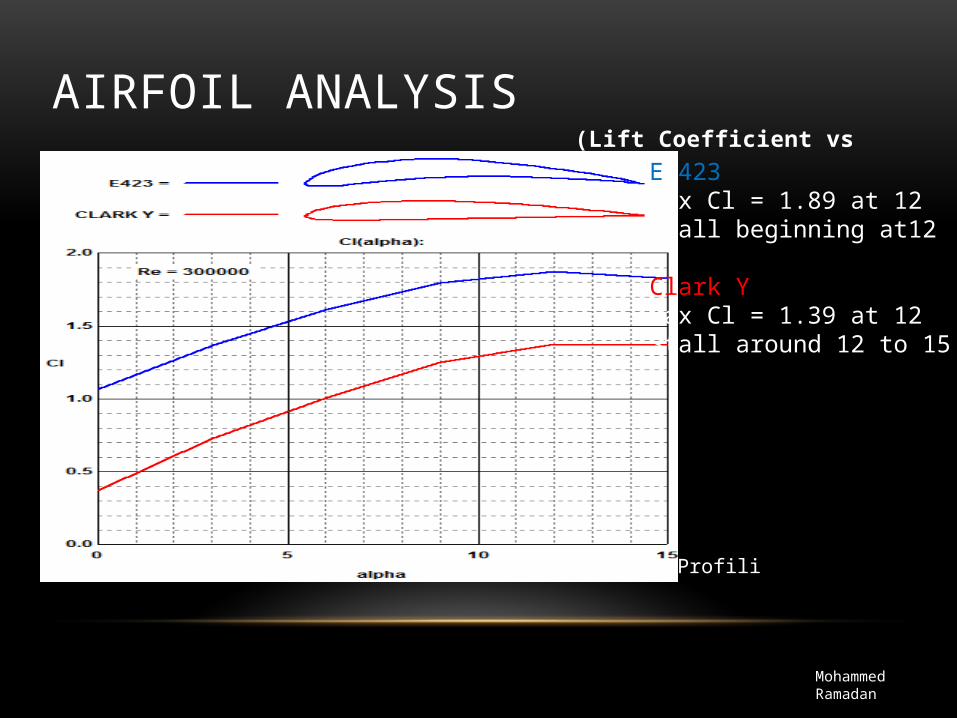
AIRFOIL ANALYSIS (Lift Coefficient vs AoA)
Mohammed Ramadan
Profili
E 423Max Cl = 1.89 at 12Stall beginning at12
Clark YMax Cl = 1.39 at 12Stall around 12 to 15
Mohammed Ramadan
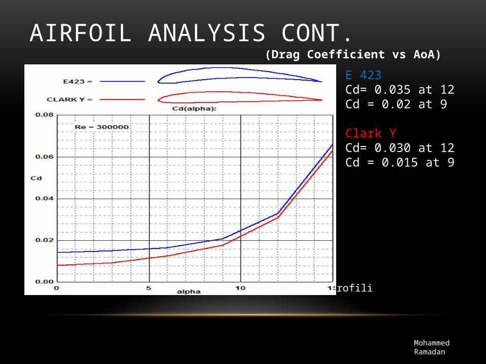
(Drag Coefficient vs AoA)
AIRFOIL ANALYSIS CONT. E 423Cd= 0.035 at 12Cd = 0.02 at 9
Clark YCd= 0.030 at 12Cd = 0.015 at 9
Profili
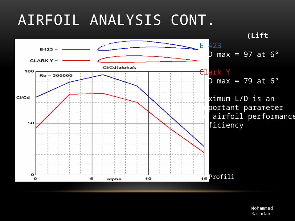
(Lift to Drag Ratio vs AoA)
Mohammed Ramadan
AIRFOIL ANALYSIS CONT.
Profili
E 423L/D max = 97 at 6°
Clark Y L/D max = 79 at 6°
Maximum L/D is an important parameter in airfoil performanceefficiency

AIRFOIL DESIGN
Mohammed Ramadan
SolidWorks & Profili
4 lightening holes
3 spar locations
Initial chord = 13 inches
Max thickness = 1.63 inches

WING PLANFORM
• Rectangular
Ideal for low speed
Ease to construct
• Tapered Harder to construct
Good for high speed
Mohammed Ramadan
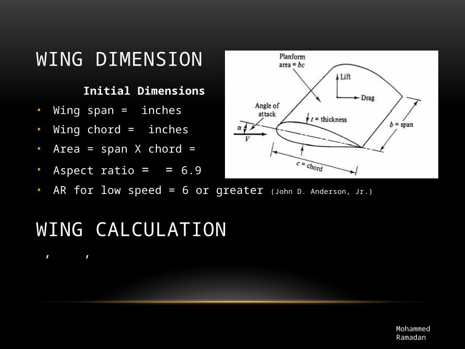
Initial Dimensions
• Wing span = inches
• Wing chord = inches
• Area = span X chord =
• Aspect ratio = = 6.9
• AR for low speed = 6 or greater (John D. Anderson, Jr.)
, ,
WING DIMENSION
Mohammed Ramadan
WING CALCULATION
• Static analysis for load distributions
• Mechanics of materials for yield strength.
WING ANALYSIS
Mohammed Ramadan

LANDING GEAR
• Tail dragger or Tricycle
• COG
• Takeoff
• Landing
Brian Martinez
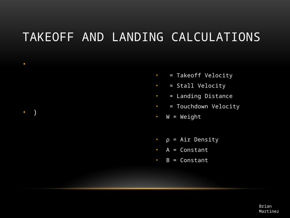
• = Takeoff Velocity
• = Stall Velocity
• = Landing Distance
• = Touchdown Velocity
• W = Weight
• ρ = Air Density
• A = Constant
• B = Constant
•
• )
TAKEOFF AND LANDING CALCULATIONS
Brian Martinez
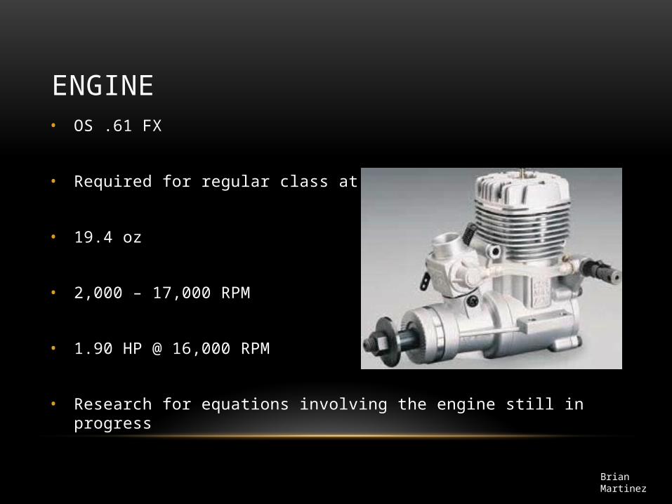
ENGINE• OS .61 FX
• Required for regular class at SAE competition
• 19.4 oz
• 2,000 – 17,000 RPM
• 1.90 HP @ 16,000 RPM
• Research for equations involving the engine still in progress
Brian Martinez

Tail End selection• We did research on three different
tail sections
•Convectional
•T-Tail
•Cruciform
• We will use a Convectional tail with a NACA-0012 airfoil
• Easy to manufacture
• Vertical tail will have a taper
• NACA airfoil is popular and should provide necessary stability
(Raymer)
Noe Caro
HORIZONTAL TAIL SECTION
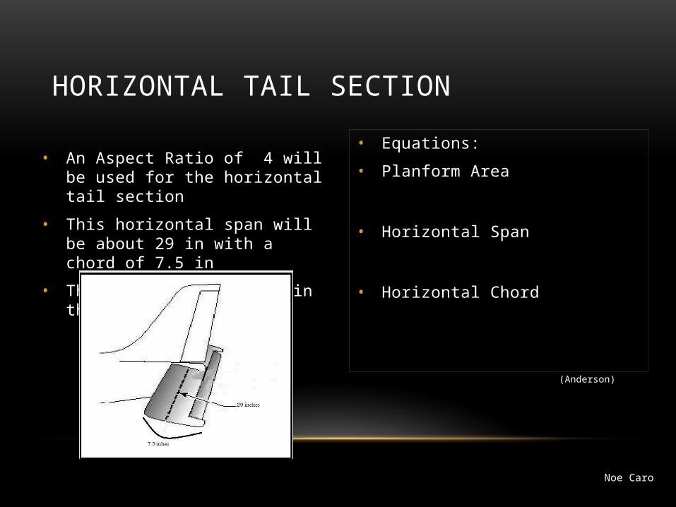
• An Aspect Ratio of 4 will be used for the horizontal tail section
• This horizontal span will be about 29 in with a chord of 7.5 in
• There will be no taper in the horizontal tail
• Equations:
• Planform Area
• Horizontal Span
• Horizontal Chord
(Anderson)
Noe Caro
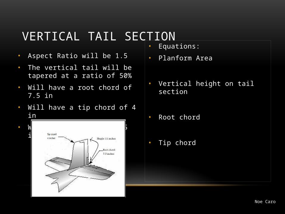
VERTICAL TAIL SECTION• Aspect Ratio will be 1.5
• The vertical tail will be tapered at a ratio of 50%
• Will have a root chord of 7.5 in
• Will have a tip chord of 4 in
• Will have a span of 11.5 in
• Equations:
• Planform Area
• Vertical height on tail section
• Root chord
• Tip chord
Noe Caro

CONCLUSION
• Calculate equations related to the airfoil, fuselage, tail wing and engine
• Put together final solid works model
• Put together a materials list
• Order materials needed to construct prototype
Noe Caro