Embed Size (px)
Citation preview
Service Manual_______________________________________________________________________________________
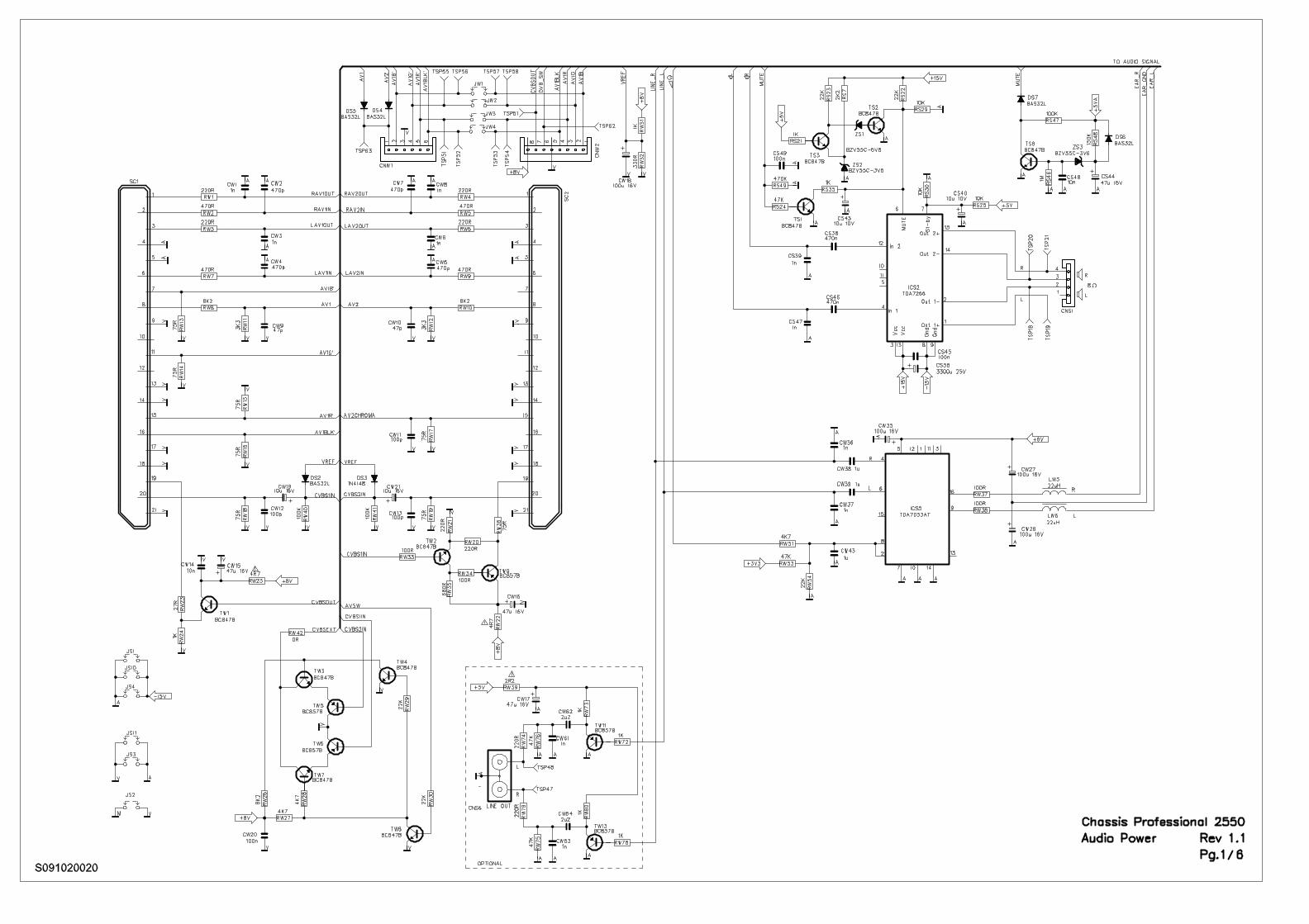
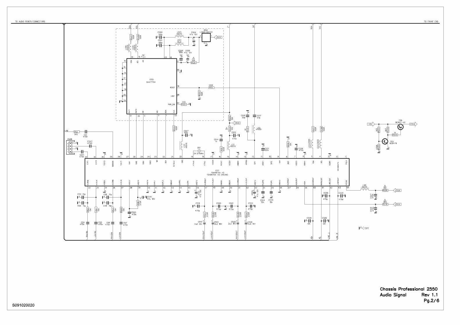
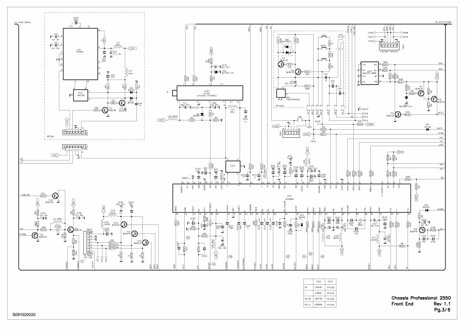
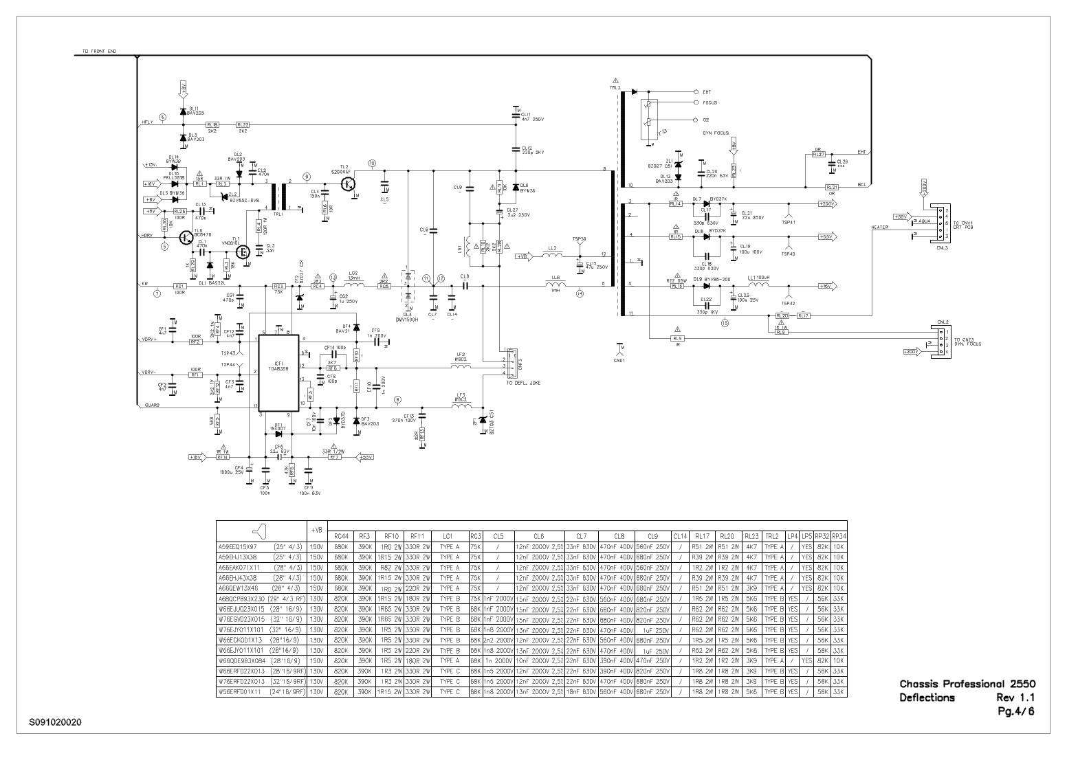
Chassis Professional 2550_______________________________________________________________________________________
Service notesAfter a repair the cables must be laid out as originally fitted to save compliance with original approval andto avoid failures or disturbances.The mains cable prevents interference from the mains supply and is part of the product approval. Forreplacement the original spare part only must be used.
Note di servizioDopo una riparazione i cavi devono essere disposti come posizionati all’origine per mantenere lacorrispondenza con le approvazioni originali ed evitare guasti o disturbi.Il cavo di alimentazione previene interferenze provenienti dalla rete elettrica ed è parte delle approvazionidel prodotto. Per la sostituzione deve essere utilizzato esclusivamente il ricambio originale.
Modifications reserved - Con riserva di modifiche
Chassis Professional 2550 service procedure
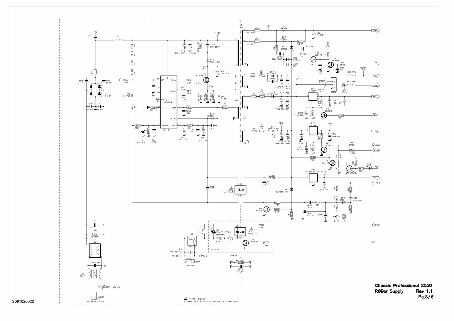
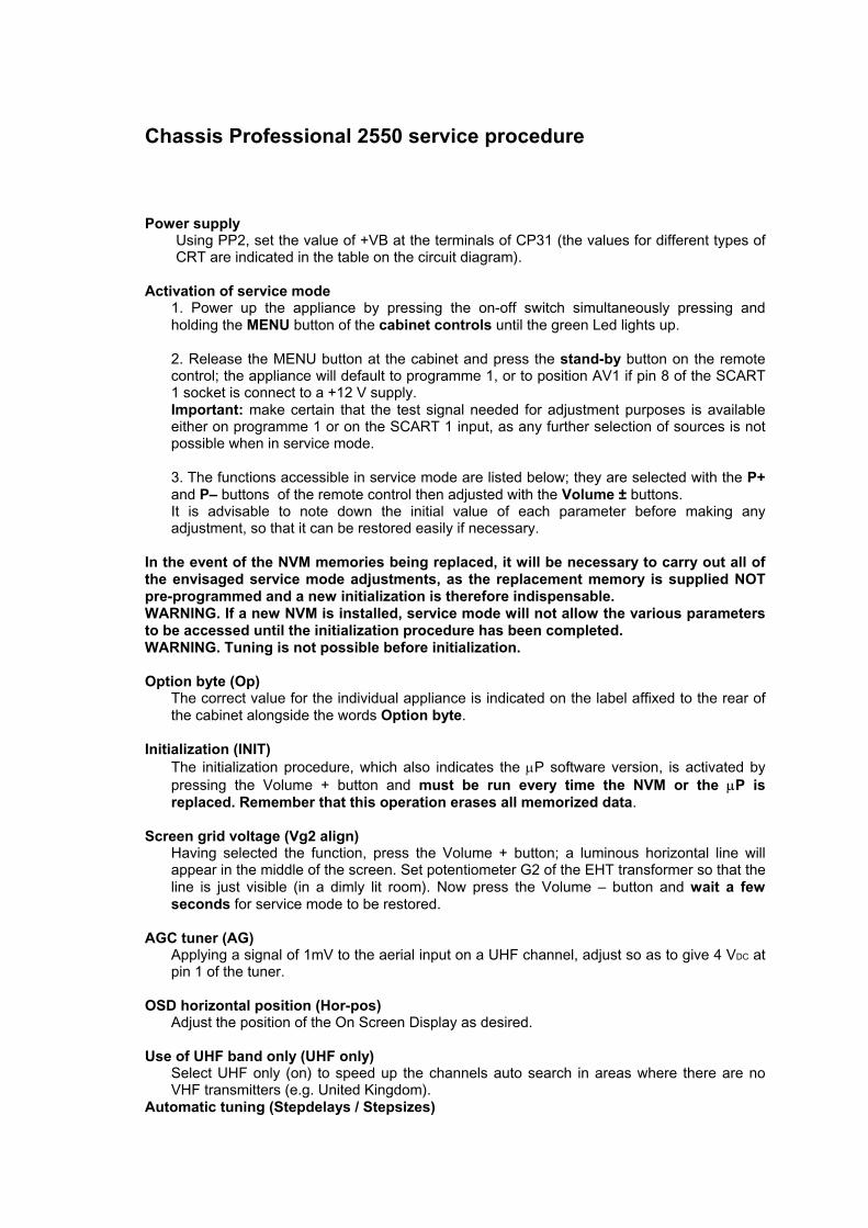
Power supplyUsing PP2, set the value of +VB at the terminals of CP31 (the values for different types ofCRT are indicated in the table on the circuit diagram).
Activation of service mode1. Power up the appliance by pressing the on-off switch simultaneously pressing andholding the MENU button of the cabinet controls until the green Led lights up.
2. Release the MENU button at the cabinet and press the stand-by button on the remotecontrol; the appliance will default to programme 1, or to position AV1 if pin 8 of the SCART1 socket is connect to a +12 V supply. Important: make certain that the test signal needed for adjustment purposes is availableeither on programme 1 or on the SCART 1 input, as any further selection of sources is notpossible when in service mode.
3. The functions accessible in service mode are listed below; they are selected with the P+and P– buttons of the remote control then adjusted with the Volume ± buttons.It is advisable to note down the initial value of each parameter before making anyadjustment, so that it can be restored easily if necessary.
In the event of the NVM memories being replaced, it will be necessary to carry out all ofthe envisaged service mode adjustments, as the replacement memory is supplied NOTpre-programmed and a new initialization is therefore indispensable.WARNING. If a new NVM is installed, service mode will not allow the various parametersto be accessed until the initialization procedure has been completed.WARNING. Tuning is not possible before initialization.
Option byte (Op)The correct value for the individual appliance is indicated on the label affixed to the rear ofthe cabinet alongside the words Option byte.
Initialization (INIT)The initialization procedure, which also indicates the µP software version, is activated bypressing the Volume + button and must be run every time the NVM or the µP isreplaced. Remember that this operation erases all memorized data.
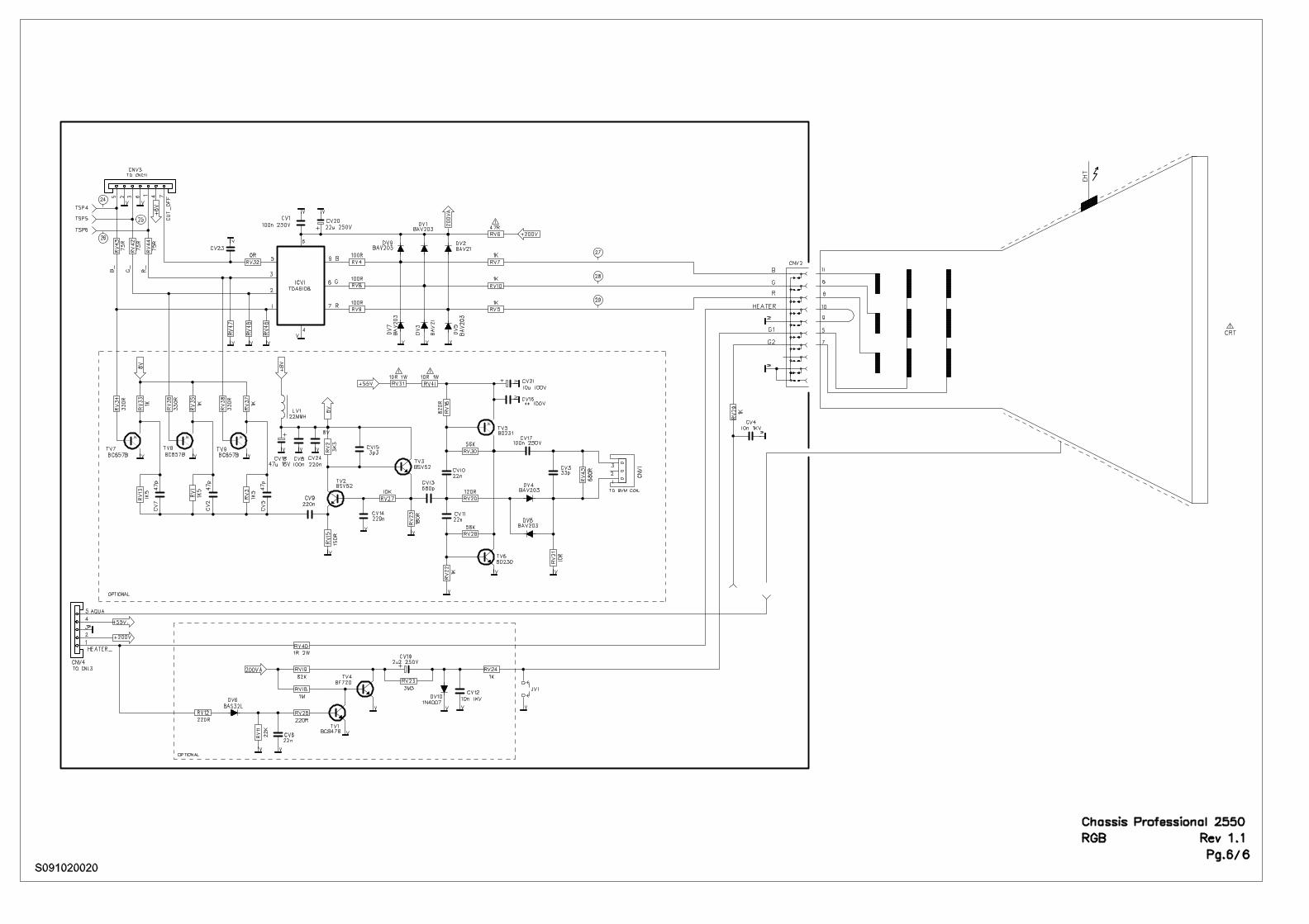
Screen grid voltage (Vg2 align)Having selected the function, press the Volume + button; a luminous horizontal line willappear in the middle of the screen. Set potentiometer G2 of the EHT transformer so that theline is just visible (in a dimly lit room). Now press the Volume – button and wait a fewseconds for service mode to be restored.
AGC tuner (AG)Applying a signal of 1mV to the aerial input on a UHF channel, adjust so as to give 4 VDC atpin 1 of the tuner.
OSD horizontal position (Hor-pos)Adjust the position of the On Screen Display as desired.
Use of UHF band only (UHF only)Select UHF only (on) to speed up the channels auto search in areas where there are noVHF transmitters (e.g. United Kingdom).
Automatic tuning (Stepdelays / Stepsizes)
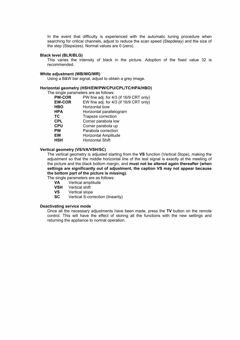
In the event that difficulty is experienced with the automatic tuning procedure whensearching for critical channels, adjust to reduce the scan speed (Stepdelay) and the size ofthe step (Stepsizes). Normal values are 0 (zero).
Black level (BLR/BLG)This varies the intensity of black in the picture. Adoption of the fixed value 32 isrecommended.
White adjustment (WB/WG/WR)Using a B&W bar signal, adjust to obtain a grey image.
Horizontal geometry (HSH/EW/PW/CPU/CPL/TC/HPA/HBO)The single parameters are as follows:
PW-COR PW fine adj. for 4/3 (if 16/9 CRT only)EW-COR EW fine adj. for 4/3 (if 16/9 CRT only)HBO Horizontal bowHPA Horizontal parallelogramTC Trapeze correctionCPL Corner parabola lowCPU Corner parabola upPW Parabola correctionEW Horizontal AmplitudeHSH Horizontal Shift
Vertical geometry (VS/VA/VSH/SC)The vertical geometry is adjusted starting from the VS function (Vertical Slope), making theadjustment so that the middle horizontal line of the test signal is exactly at the meeting ofthe picture and the black bottom margin, and must not be altered again thereafter (whensettings are significantly out of adjustment, the caption VS may not appear becausethe bottom part of the picture is missing).The single parameters are as follows:
VA Vertical amplitudeVSH Vertical shiftVS Vertical slopeSC Vertical S-correction (linearity)
Deactivating service modeOnce all the necessary adjustments have been made, press the TV button on the remotecontrol. This will have the effect of storing all the functions with the new settings andreturning the appliance to normal operation.
Procedura servizio Chassis Professional 2550
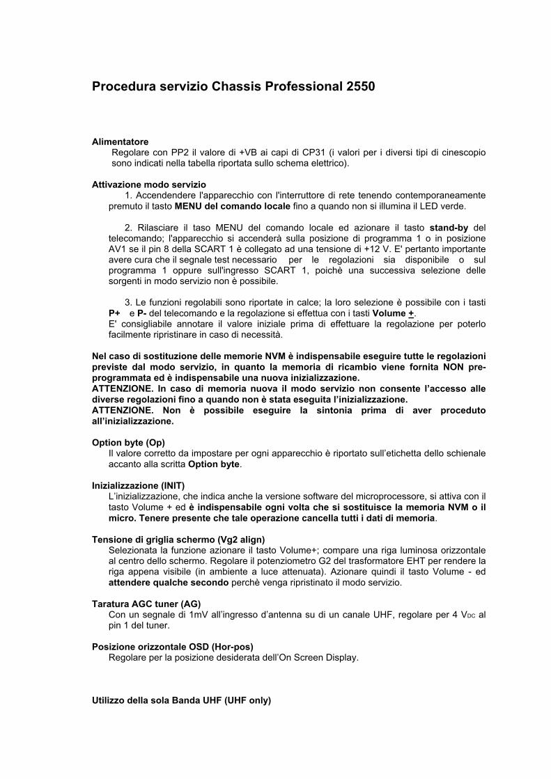
AlimentatoreRegolare con PP2 il valore di +VB ai capi di CP31 (i valori per i diversi tipi di cinescopiosono indicati nella tabella riportata sullo schema elettrico).
Attivazione modo servizio1. Accendendere l'apparecchio con l'interruttore di rete tenendo contemporaneamente
premuto il tasto MENU del comando locale fino a quando non si illumina il LED verde.
2. Rilasciare il taso MENU del comando locale ed azionare il tasto stand-by deltelecomando; l'apparecchio si accenderà sulla posizione di programma 1 o in posizioneAV1 se il pin 8 della SCART 1 è collegato ad una tensione di +12 V. E' pertanto importanteavere cura che il segnale test necessario per le regolazioni sia disponibile o sulprogramma 1 oppure sull'ingresso SCART 1, poichè una successiva selezione dellesorgenti in modo servizio non è possibile.
3. Le funzioni regolabili sono riportate in calce; la loro selezione è possibile con i tastiP+ e P- del telecomando e la regolazione si effettua con i tasti Volume +.E' consigliabile annotare il valore iniziale prima di effettuare la regolazione per poterlofacilmente ripristinare in caso di necessità.
Nel caso di sostituzione delle memorie NVM è indispensabile eseguire tutte le regolazionipreviste dal modo servizio, in quanto la memoria di ricambio viene fornita NON pre-programmata ed è indispensabile una nuova inizializzazione.ATTENZIONE. In caso di memoria nuova il modo servizio non consente l’accesso allediverse regolazioni fino a quando non è stata eseguita l’inizializzazione.ATTENZIONE. Non è possibile eseguire la sintonia prima di aver procedutoall’inizializzazione.
Option byte (Op)Il valore corretto da impostare per ogni apparecchio è riportato sull’etichetta dello schienaleaccanto alla scritta Option byte.
Inizializzazione (INIT)L’inizializzazione, che indica anche la versione software del microprocessore, si attiva con iltasto Volume + ed è indispensabile ogni volta che si sostituisce la memoria NVM o ilmicro. Tenere presente che tale operazione cancella tutti i dati di memoria.
Tensione di griglia schermo (Vg2 align)Selezionata la funzione azionare il tasto Volume+; compare una riga luminosa orizzontaleal centro dello schermo. Regolare il potenziometro G2 del trasformatore EHT per rendere lariga appena visibile (in ambiente a luce attenuata). Azionare quindi il tasto Volume - edattendere qualche secondo perchè venga ripristinato il modo servizio.
Taratura AGC tuner (AG)Con un segnale di 1mV all’ingresso d’antenna su di un canale UHF, regolare per 4 VDC alpin 1 del tuner.
Posizione orizzontale OSD (Hor-pos)Regolare per la posizione desiderata dell’On Screen Display.
Utilizzo della sola Banda UHF (UHF only)
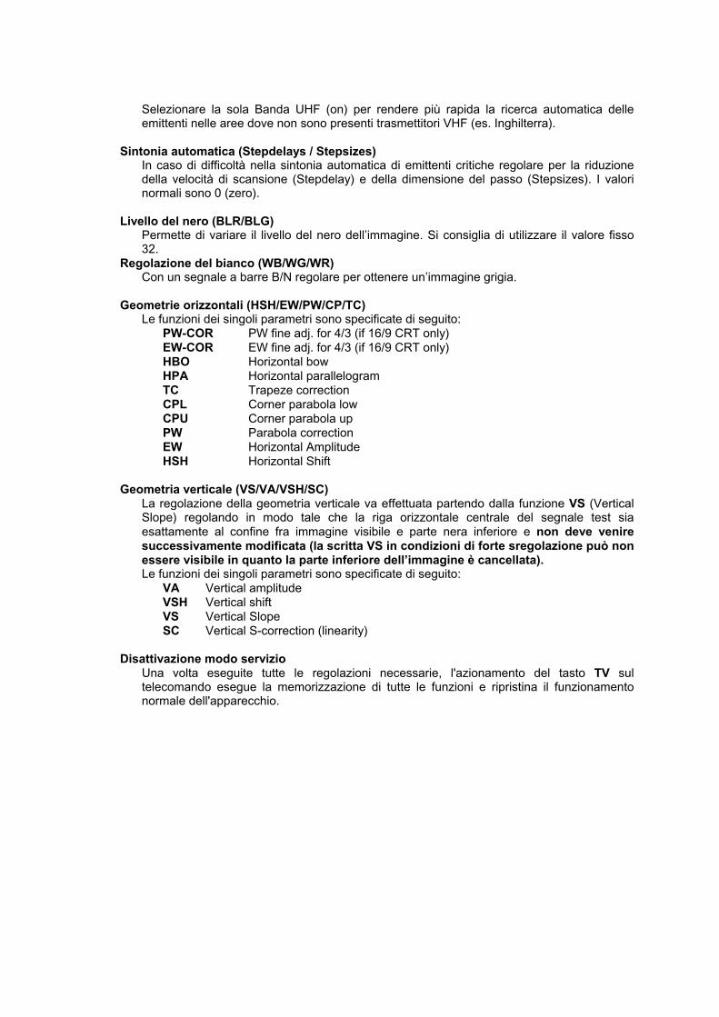
Selezionare la sola Banda UHF (on) per rendere più rapida la ricerca automatica delleemittenti nelle aree dove non sono presenti trasmettitori VHF (es. Inghilterra).
Sintonia automatica (Stepdelays / Stepsizes)In caso di difficoltà nella sintonia automatica di emittenti critiche regolare per la riduzionedella velocità di scansione (Stepdelay) e della dimensione del passo (Stepsizes). I valorinormali sono 0 (zero).
Livello del nero (BLR/BLG)Permette di variare il livello del nero dell’immagine. Si consiglia di utilizzare il valore fisso32.
Regolazione del bianco (WB/WG/WR)Con un segnale a barre B/N regolare per ottenere un’immagine grigia.
Geometrie orizzontali (HSH/EW/PW/CP/TC)Le funzioni dei singoli parametri sono specificate di seguito:
PW-COR PW fine adj. for 4/3 (if 16/9 CRT only)EW-COR EW fine adj. for 4/3 (if 16/9 CRT only)HBO Horizontal bowHPA Horizontal parallelogramTC Trapeze correctionCPL Corner parabola lowCPU Corner parabola upPW Parabola correctionEW Horizontal AmplitudeHSH Horizontal Shift
Geometria verticale (VS/VA/VSH/SC)La regolazione della geometria verticale va effettuata partendo dalla funzione VS (VerticalSlope) regolando in modo tale che la riga orizzontale centrale del segnale test siaesattamente al confine fra immagine visibile e parte nera inferiore e non deve veniresuccessivamente modificata (la scritta VS in condizioni di forte sregolazione può nonessere visibile in quanto la parte inferiore dell’immagine è cancellata).Le funzioni dei singoli parametri sono specificate di seguito:
VA Vertical amplitudeVSH Vertical shiftVS Vertical SlopeSC Vertical S-correction (linearity)
Disattivazione modo servizioUna volta eseguite tutte le regolazioni necessarie, l'azionamento del tasto TV sultelecomando esegue la memorizzazione di tutte le funzioni e ripristina il funzionamentonormale dell'apparecchio.
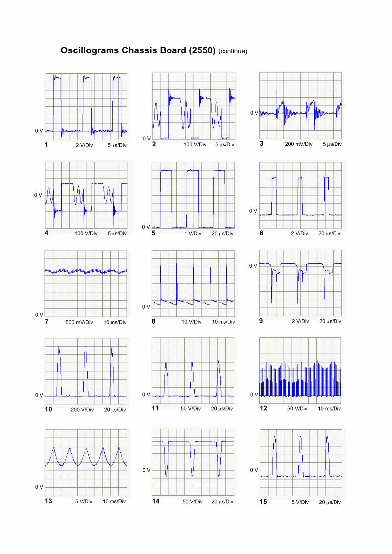
Oscillograms Chassis Board (2550) (continue)
1 2 V/Div 5 µs/Div
0 V
2 100 V/Div 5 µs/Div0 V
3 200 mV/Div 5 µs/Div
0 V
4 100 V/Div 5 µs/Div
0 V
5 1 V/Div 20 µs/Div0 V
6 2 V/Div 20 µs/Div
0 V
7 500 mV/Div 10 ms/Div
0 V8 10 V/Div 10 ms/Div
0 V
9 2 V/Div 20 µs/Div
0 V
10 200 V/Div 20 µs/Div
0 V
11 50 V/Div 20 µs/Div
0 V
12 50 V/Div 10 ms/Div
0 V
13 5 V/Div 10 ms/Div
0 V
14 50 V/Div 20 µs/Div
0 V
15 5 V/Div 20 µs/Div
0 V
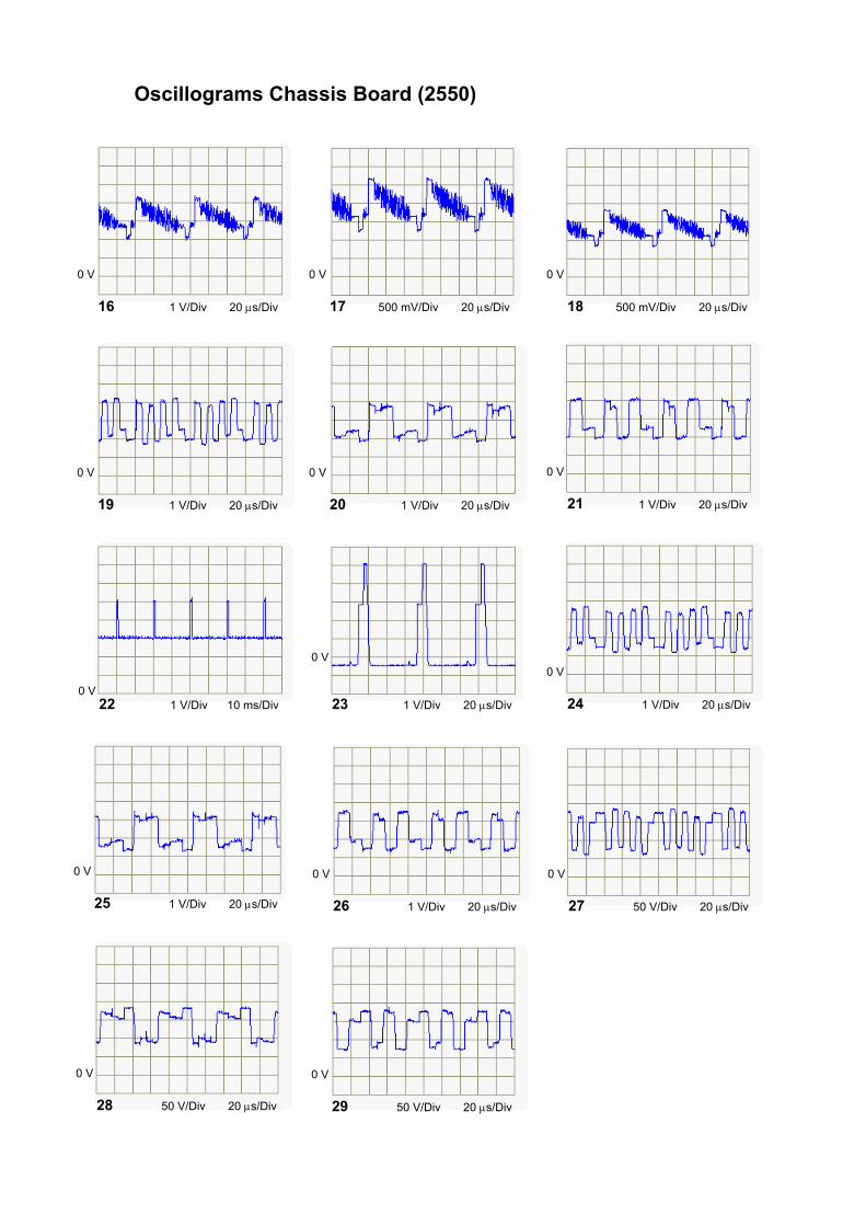
Oscillograms Chassis Board (2550)
16 1 V/Div 20 µs/Div
0 V
17 500 mV/Div 20 µs/Div
0 V
18 500 mV/Div 20 µs/Div
0 V
19 1 V/Div 20 µs/Div
0 V
20 1 V/Div 20 µs/Div
0 V
21 1 V/Div 20 µs/Div
0 V
22 1 V/Div 10 ms/Div0 V
23 1 V/Div 20 µs/Div
0 V
24 1 V/Div 20 µs/Div
0 V
25 1 V/Div 20 µs/Div
0 V
26 1 V/Div 20 µs/Div
0 V
27 50 V/Div 20 µs/Div
0 V
28 50 V/Div 20 µs/Div
0 V
29 50 V/Div 20 µs/Div
0 V