Embed Size (px)
Citation preview

Electric cooling fans have been with us for decades, and although staged two- and three-speed fans are still part of the picture,
more and more vehicles are being equipped with pulse width modulat-ed fans. There’s a simple reason: The greater precision of pulse width mod-ulation translates to a small but worth-while increase in fuel economy. As a result, the Environmental Protection Agency gives the carmakers a special credit toward corporate average fuel economy (CAFE).
As we noted in the air condition-ing report in the April 2015 issue of Motor, the credit is just .9 gram of carbon dioxide per mile, and if you’re wondering what that has to do with fuel economy, you should know that the EPA calculates fuel economy in grams CO2/mile using a conversion factor that translates to miles per gal-lon. The carmakers need to save every gram they can to meet the ever-tight-ening fuel economy regulations. And because they can bank credits for later use if sales of fuel-thirsty models do unexpectedly well, they’re installing all the fuel-saving systems they can, even
before they’re up against really tough CAFE mpg/CO2 numbers.
What makes pulse width modulated fans more efficient is that they can be controlled to an infi nitely variable speed, so compared with a two-stage fan, there’s no compromise that forces the fan system to run at high speed because low speed is just a bit too low.
Pulse width signals for the fans are produced by the engine computer, which is pretty logical when you think about it because the cooling fans are part of the powertrain. However, on some Toyota products there’s a CAN bus to a front control module, and
18 August 2015
CHECK ITS PULSE!FAN CONTROL SYSTEMS
BY PAUL WEISSLER
If vehicle systems require less power to operate, engines will burn less fuel.
This cause & effect relationship explains the growing popularity of pulse width
modulated cooling fan control systems.
Pho
to:T
hin
ksto
ck
august.indd 1 7/20/15 5:06 PM
that module produces the pulse signal.The signals go to an electronic
control module on the fan assembly, which translates them into the pulse width operation of the fan motors. That’s been the approach used by Chrysler since the PT Cruiser turbo and (except for the just-mentioned CAN bus signal transmission from the front control module) is really not noticeably different from what’s do-ne by Lexus on its LS 460 model. In fact, the only real difference between these systems is the control strategy for the pulse width. Unfortunately, the carmakers usually don’t give you that.
What you do know, however, are the inputs—coolant temperature, ambient temperature (Chrysler), en-gine rpm, vehicle speed and air con-ditioning status, plus perhaps others, depending on the system. The specif-ic input for a/c might be an algorithm or just a sensor reading. On most GM products, for example, engine oil temperature is an input to the fan strategy and, like any vehicle with the specific sensor, the a/c input is refrig-erant pressure.
The “infinitely variable fan” is not always likely to be truly infinitely variable. On the Cadillac CTS, for example, the fan module, which is controlled by the PCM, offers six dif-ferent pulse width percentages be-tween 0% and 90%, starting at 4% to 5%. So if your scan tool can com-mand duty cycles, you’ll find that you can get only the ones programmed in, and they’ll not be the same across the board on GM products. In fact, you may see a difference in models within a single make, because the percentages available will be ones that will not produce a lot of noise or vibration. The percentages the scan tool can command on the 2014 CTS with the 2.0L turbo are approximate-ly 18%, 54%, 67%, 85% and 90%. Yes, the higher percentages are al-most sure to be noisier than the low-er ones, but they provide a balance between noise level and the cooling requirement. And with the factor of vibration to be considered, 67% just
19August 2015
might be a better choice than 61%, for example. That said, the duty cycle percentage is subject to some vari-ation, particularly if the battery had been run down and the charging sys-tem was operating at max as a result.
Always command fan speed in an ascending sequence, as a skip could confuse the PCM and possibly stop fan operation. Don’t always expect an instant response when you’re commanding a duty cycle. As long as there’s a commanded change within about 15 seconds, that’s okay.
Obviously, the first test for a fan circuit is, Does it work at all? Usually, a warm engine with the a/c turned to Max should result in the fan turning on. If it doesn’t, the next step is to check for trouble codes. These are
likely to be for an open or short in the output circuit (which could be the fan[s] or module, of course), or possi-bly a coolant sensor issue.
No codes and no fan operation? The most basic check is for any obvi-ous external damage to connectors or the harness, or the physical mounting of the fan/motor/shroud assembly. If there is none, unplug the connector at the fan assembly and try to operate the fan by hand (both fans if the vehi-cle has two). It should spin smoothly; if it doesn’t, not only is the fan likely bad, but there may be a blown fuse due to excess current draw.
We should point out, however, that although high current draw may blow a fuse, most fan circuits are fused at 30 to 40A and a high current draw
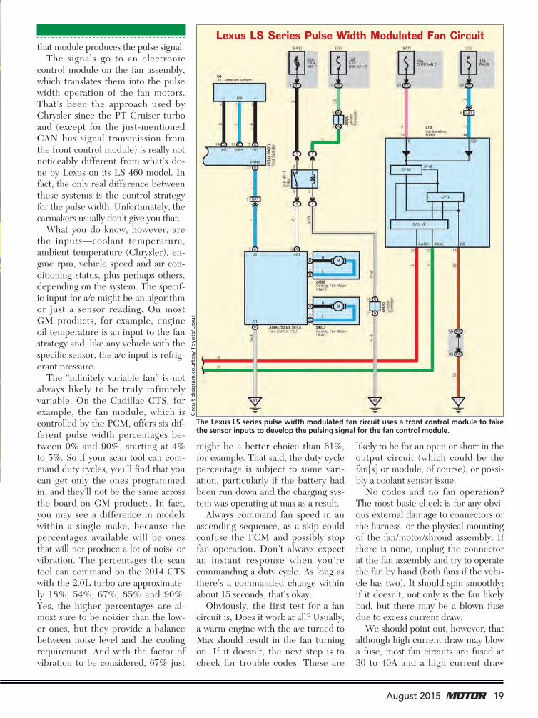
The Lexus LS series pulse width modulated fan circuit uses a front control module to take the sensor inputs to develop the pulsing signal for the fan control module.
Lexus LS Series Pulse Width Modulated Fan Circuit
Cir
cuit
dia
gra
m c
ou
rtes
y To
yota
/Lex
us
august.indd 2 7/20/15 5:06 PM

22 August 2015
Check Its Pulse! Fan Control Systems
from a binding motor might be just below what it takes to blow the fuse. Every fan system has a different cur-rent draw, and although the ones we’ve tried are usually just into dou-ble figures for high speed, we’re not guaranteeing that’s a rule of thumb for an SUV with a towing package. You might find the current draw buried somewhere in the OE specs.
Occasionally we hear about the oppo-site—a fan that spins whenever the igni-tion is on, usually from a short or short-ed relay or, for those fans with normally closed relays, from an open circuit.
But where the issue is an inter-mittent fan or one that may be run-ning slow, a technician usually has to check the inputs for accuracy and then look for a change in the duty cycle and the fan speeds as a result, when the inputs indicate the need for
more fan cooling. Toyota does give you a starting reference for the LS series. With the a/c off and the cool-ant temperature below 198°F, the fan should be off. It should start spinning on low speed when coolant tempera-ture is about 201°F (give it a couple of degrees either way as a tolerance), and should increase gradually, run-ning at maximum speed when coolant temperature exceeds 212°F.
You might not be able to find these specifications with other makes. In fact, we checked all three domestic nameplates and none gave us num-bers like these. At Ford, for example, the only quick test is to put the a/c on Max and the blower on High, after which the fan should operate with the engine running. If it doesn’t, Ford puts you through a standard diagnos-tic procedure (cooling system includ-
ing thermostat, power, ground).The basic test for duty cycle is with
an oscilloscope, which you can con-nect to the powertrain computer in-put at the module on the fan assem-bly or, as Toyota recommends for the LS 460, to the equivalent connec-tor on the front controller (terminal labeled FAN 1 with wire to terminal S1 on the Fan Control ECU). With the engine not running, of course, you should get a scope pattern that looks like a flat line just above the ground reference line. When the fan starts to run, you’ll see a graph line with very brief ground lines. As it speeds up, the ground lines get wider, as shown in the illustration at the bottom of this page.
Why would you be checking the duty cycle at all if the fan is running? Fair question. If the engine is running hot and you can’t find another rea-son, while the fan speed doesn’t seem or sound particularly high, either the commanded duty cycle is off (low) or the fan is incapable of a full response.
However, the OE approach seems to be focused on hard failures—that is, when the fan doesn’t spin or doesn’t stop spinning. You’ll find diagnostic trees or charts to check for circuit opens and shorts for those problems. If you do find a wiring short, you’ll fix it, of course, but al-so see if the fan module still works, rather than just routinely order a re-placement. A common design charac-teristic is internal thermal protection against a short.
Waveform 1 Waveform 2 Waveform 3
1V/Div.
< Ground < Ground < Ground
20mS/Div. 20mS/Div. 20mS/Div.
1V/Div. 1V/Div.
Wav
efo
rms
cou
rtes
y To
yota
/Lex
us
These sample waveforms show the scope patterns for a pulse width modulated fan. Waveform 1 is a flat line, indi-cating the motor is off. In waveform 2 there’s a considerable amount of time when the waveform is at the ground level, which is for a duty cycle in the 50% range. Waveform 3 shows some time when the waveform is at the ground level, but much less than in waveform 2. This is for a duty cycle in the 60% to 70% range.
The Lexus LS series pulse width modulated fan assembly consists of a main fan, a smaller subfan, a cooling fan electronic control unit and a harness from the engine control module.
Subfan
From ECM
Reservoir Tank Cooling Fan ECU
Fan Shroud
Main Fan
Radiator
Illu
stra
tio
n c
ou
rtes
y To
yota
/Lex
us
august.indd 3 7/20/15 5:07 PM

Stepped Fan Speeds
Although the pulse width modulated fan is going to take over, primari-ly because of the CAFE credit, the majority of what you’ll still see in the shop is a fan circuit with stepped in-creases in rpm. The most common stepped-speed circuit is the two-speed, with a pair of relays. The typi-cal circuit closes a relay to turn on the fan at the motor speed, starting with the low-speed relay. At a specifi c set of conditions, the command comes to close a second relay for the high-speed fan. That’s pretty straightfor-ward. If the system has a single motor and fan, that low speed will be from a circuit through a dropping resistor.
These circuits have been used for decades, but the input sensors and output triggers to the PCM or ECM have been changed many times. So here’s where you need the OE ser-vice information, if it’s provided. If it isn’t, you’re often fl ying blind and have to hope the “norms” apply—that is, you look for the fan to come on at low speed when the engine is just above fully warmed up (block the front end airfl ow, if necessary). And then you can check for high speed with the a/c turned to Max.
An understanding of the system is necessary, particularly when the fans work on one speed only. Some vehi-cles have two two-speed motors, and here’s where a cooling problem could be less than obvious if you don’t check the wiring diagrams and look for a fan system operating strategy. That can make you aware that a two-fan system, certainly if it’s supposed to provide three speeds, pretty well indicates the two fans are different. A loss of middle speed could result in the engine run-ning too hot until high speed kicks in, something that could easily be missed.
On a late-model Nissan Altima 4-cylinder, for example, low fan speed is achieved by closing relay No. 1 (low-speed fan motor), medium speed is achieved is by closing relay 2 and high speed is achieved by closing relays 2
and 3. This system sends the signals from the ECM on the high-speed CAN bus to the intelligent power distribution module (IPDM), which holds the No. 1 relay and ECM relay, to the appropriate fan relay.
Three relays in the circuit does not mean three speeds. In a common GM circuit, the low speed (No. 1) is a se-ries circuit; the high speed is a parallel circuit and the additional relay (No. 2) performs different functions for each.
Consider the late-model Chevy Im-pala, a W-platform car. The engine control module has two relay-ground terminals—one for the low speed and the other for the series-parallel relay. For low fan speed, the ECM grounds the low-speed relay coil, closing the relay contacts. So voltage fl ows through the left side cooling fan motor, through one circuit provided by the series-parallel relay contacts, through the right side cooling fan mo-tor to ground. This is the series circuit, and both fans run at low speed.
For high speed, the ECM grounds both the series-parallel and high-speed relays. The switching of the se-ries-parallel relay contacts moves the low-speed circuit to its own ground for the left-side fan motor. The grounding of the high-speed relay completes a powered circuit directly through the right-side fan motor to ground, and both fans run at high speed.
Initial diagnosis is somewhat like that for pulse width modulated fans. Does the fan system work at all? You
24 August 2015
Check Its Pulse! Fan Control Systems
Pho
to: P
aul W
eiss
ler
Check fan operation by trying to spin it with the wiring connector unplugged. If you feel any roughness or if the spin is very weak, indicating binding, the fan and/or fan motor will probably require replacement.
Illu
stra
tio
ns
cou
rtes
y N
issa
n
The Nissan Altima’s fan operating strategy is based on coolant temperature and a/c status (On/Off). Note that like high and low speeds, the middle speed comes on under very specifi c conditions.
august.indd 4 7/21/15 8:45 AM

may want to hot-wire the fan motors or use a scan tool to see if you can command operation. If you can’t, look for physical damage and try to oper-ate the fans by hand. Nothing so far? Check the inputs to the PCM.
Where problems with stepped fans log a trouble code, the start of the diagnostic approach is pretty well dictated. However, during the ef-fort to pinpoint them, the problems with stepped fans are often blamed on the relays or the electronic boxes that provide the primary control—that is, totally integrated power module
(TIPM) and intelligent power dis-tribution module (IPDM). But even more than with the pulse width modu-lated type, excessive current draw just short of blowing a fuse is also an issue. Furthermore, logic says that if there’s a specific fan outage or rpm issue caused by a relay circuit, the fan oper-ating strategy should indicate that, and tell you which one. That doesn’t mean the particular relay is bad, of course, but looking at fan strategy should keep you on course for the right circuit.
Although most electric fan prob-lems (except for a binding motor) are
in the electrical area, the fan mounting is an often-ignored area. We don’t face the issue of an engine-mounted fan hitting the radiator as a result of dete-riorated engine mounts on passenger cars very much anymore, but if the fan motor is loose on the shroud frame, it can produce noise. Also, if the loose mounting allows the fan blades to make any contact with the shroud as-sembly, that not only could cause a fuse to blow but could damage the fan, so it has to be replaced.
26 August 2015
Check Its Pulse! Fan Control Systems
400 millionThat’s how many Jiffy-tite parts are in service worldwide today. In fact, chances are, whether repairing an automatic transmission or building a
replacement heat exchanger, the OE used Jiffy-tite fluid fittings.
Replace a Jiffy-tite with a Jiffy-tite to maintain premium quality.
888.605.7788 • aftermarket.jiffy-tite.com
®®THE WORLD LEADER IN OILCOOLER CONNECTORS
Replace a Jiffy-tite with a Jiffy-tite to maintain premium quality. Replace a Jiffy-tite with a Jiffy-tite to maintain premium quality. Replace a Jiffy-tite with a Jiffy-tite to maintain premium quality. Replace a Jiffy-tite with a Jiffy-tite to maintain premium quality. Replace a Jiffy-tite with a Jiffy-tite to maintain premium quality. Replace a Jiffy-tite with a Jiffy-tite to maintain premium quality. Replace a Jiffy-tite with a Jiffy-tite to maintain premium quality. Replace a Jiffy-tite with a Jiffy-tite to maintain premium quality. Replace a Jiffy-tite with a Jiffy-tite to maintain premium quality. Replace a Jiffy-tite with a Jiffy-tite to maintain premium quality. Replace a Jiffy-tite with a Jiffy-tite to maintain premium quality. Replace a Jiffy-tite with a Jiffy-tite to maintain premium quality. Replace a Jiffy-tite with a Jiffy-tite to maintain premium quality. Replace a Jiffy-tite with a Jiffy-tite to maintain premium quality. Replace a Jiffy-tite with a Jiffy-tite to maintain premium quality. Replace a Jiffy-tite with a Jiffy-tite to maintain premium quality. Replace a Jiffy-tite with a Jiffy-tite to maintain premium quality. Replace a Jiffy-tite with a Jiffy-tite to maintain premium quality. Replace a Jiffy-tite with a Jiffy-tite to maintain premium quality. Replace a Jiffy-tite with a Jiffy-tite to maintain premium quality. Replace a Jiffy-tite with a Jiffy-tite to maintain premium quality. Replace a Jiffy-tite with a Jiffy-tite to maintain premium quality. Replace a Jiffy-tite with a Jiffy-tite to maintain premium quality. Replace a Jiffy-tite with a Jiffy-tite to maintain premium quality. Replace a Jiffy-tite with a Jiffy-tite to maintain premium quality. Replace a Jiffy-tite with a Jiffy-tite to maintain premium quality. Replace a Jiffy-tite with a Jiffy-tite to maintain premium quality. Replace a Jiffy-tite with a Jiffy-tite to maintain premium quality. Replace a Jiffy-tite with a Jiffy-tite to maintain premium quality. Replace a Jiffy-tite with a Jiffy-tite to maintain premium quality. Replace a Jiffy-tite with a Jiffy-tite to maintain premium quality. Replace a Jiffy-tite with a Jiffy-tite to maintain premium quality. Replace a Jiffy-tite with a Jiffy-tite to maintain premium quality. Replace a Jiffy-tite with a Jiffy-tite to maintain premium quality. Replace a Jiffy-tite with a Jiffy-tite to maintain premium quality. Replace a Jiffy-tite with a Jiffy-tite to maintain premium quality. Replace a Jiffy-tite with a Jiffy-tite to maintain premium quality. Replace a Jiffy-tite with a Jiffy-tite to maintain premium quality. Replace a Jiffy-tite with a Jiffy-tite to maintain premium quality. Replace a Jiffy-tite with a Jiffy-tite to maintain premium quality. Replace a Jiffy-tite with a Jiffy-tite to maintain premium quality. Replace a Jiffy-tite with a Jiffy-tite to maintain premium quality. Replace a Jiffy-tite with a Jiffy-tite to maintain premium quality. Replace a Jiffy-tite with a Jiffy-tite to maintain premium quality. Replace a Jiffy-tite with a Jiffy-tite to maintain premium quality. Replace a Jiffy-tite with a Jiffy-tite to maintain premium quality. Replace a Jiffy-tite with a Jiffy-tite to maintain premium quality. Replace a Jiffy-tite with a Jiffy-tite to maintain premium quality. Replace a Jiffy-tite with a Jiffy-tite to maintain premium quality. Replace a Jiffy-tite with a Jiffy-tite to maintain premium quality. Replace a Jiffy-tite with a Jiffy-tite to maintain premium quality. Replace a Jiffy-tite with a Jiffy-tite to maintain premium quality. Replace a Jiffy-tite with a Jiffy-tite to maintain premium quality. Replace a Jiffy-tite with a Jiffy-tite to maintain premium quality. Replace a Jiffy-tite with a Jiffy-tite to maintain premium quality. Replace a Jiffy-tite with a Jiffy-tite to maintain premium quality. Replace a Jiffy-tite with a Jiffy-tite to maintain premium quality. Replace a Jiffy-tite with a Jiffy-tite to maintain premium quality. Replace a Jiffy-tite with a Jiffy-tite to maintain premium quality. Replace a Jiffy-tite with a Jiffy-tite to maintain premium quality. Replace a Jiffy-tite with a Jiffy-tite to maintain premium quality. Replace a Jiffy-tite with a Jiffy-tite to maintain premium quality. Replace a Jiffy-tite with a Jiffy-tite to maintain premium quality. Replace a Jiffy-tite with a Jiffy-tite to maintain premium quality. Replace a Jiffy-tite with a Jiffy-tite to maintain premium quality.
888.605.7788 • aftermarket.jiffy-tite.com
Replace a Jiffy-tite WITH a Jiffy-titeReplace a Jiffy-tite WITH a Jiffy-tite
Circle #18
This article can be found online at www.motormagazine.com.
Cooling Fan SpeedCooling Fan Relay
1 2 3
Stop (OFF) Off Off Off
Low (LOW) On Off Off
Middle (MID) Off On Off
High (HI) Off On On
The Nissan Altima’s fan relay operation strategy relies on three separate relays being on or off to provide three fan speeds, plus Off.
Ch
art
cou
rtes
y N
issa
n
august.indd 5 7/20/15 5:08 PM