Embed Size (px)
Citation preview

One Stanton Street | Marinette, WI 54143-2542, USA | +1-715-735-7411 | www.ansul.com
© 2018 Johnson Controls. All rights reserved. All specifications and other information shown were current as of document revision date and are subject to change without notice. | Form No. F-2013368-01_A4
DATA SHEET
CHECKFIRE 110Detection and Actuation System
Featuresn Supervised power, detection, and release circuitsn LED system status indicatorsn External primary power with an internal reserve power sourcen Selectable release time delayn Automatic and/or manual actuationn Electric “DELAY/Reset/Silence” buttonn “PUSH To Activate / Alarm When Lit” electric manual
activation buttonn Color-coded “Plug and Play” cable connectionsn Cables provide quick installation and easy replacementn 85 dB internal soundern System isolate featuren Dust and water tight (IP67 rated)n Designed for harsh environmentsn Compact sizen Adjustable mounting bracket
ApplicationThe CHECKFIRE 110 Detection and Actuation System is typically used with an ANSUL® A-101 or LVS Vehicle Fire Suppression System for 24-hour protection of equipment. The system is designed for vehicles and equipment in extreme environmental and physical conditions.Industries where vehicles use CHECKFIRE 110 Systems:n Forestry n Land fillsn Agriculture n Waste disposaln Construction n Miningn Public Transportationn Public Utilities
DescriptionThe CHECKFIRE 110 Automatic Detection and Actuation System provides supervised input/output circuits to activate an ANSUL fire suppression system. Upon detecting a fire condition, the control module activates the release circuit resulting in the discharge of an expellant gas cartridge initiat-ing fire suppression system operation.
Operating components include the control module; spot thermal detectors; linear detectors; electric manual actuators; PADs (Protracting Actuation Device); electric-pneumatic actua-tors; and power, detection, and release cables. The entire system is electronics based for supervision, communication, and control of system components.
009257
Typical System ConnectionsThe CHECKFIRE 110 Control Module includes four cable leads with corresponding color-coded connectors for ease of installation.
System Cabling: Enables communication and control of components.n IP67 connectionsn Color-coded, anti-vibration connectorsn Integral connectors on each end of cablen Multiple lengths for versatilityn Temperature rating: 302 °F (150 °C)
Detection Circuit Lead: Permits multiple-detection options using detection circuit cable and tees for the main detection trunk and branch lines.n Electric manual actuatorsn Linear detectorsn Spot thermal detectors
Release Circuit Lead: Connects to a maximum of 2 electric-pneumatic actuators installed on agent tank expellant gas cartridges using release circuit cable(s), tee (needed on second tank), and release circuit drop cable(s).
External Power Circuit Lead: Provides a direct connection to the vehicle power source using power circuit cable(s) and a single fused power circuit cable.
Alarm Output Lead: Connects to vehicle electronics (by others) as needed.
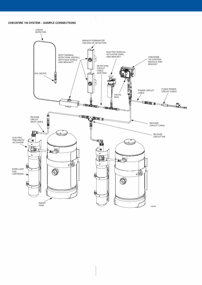
AGENT TANK
EXPELLANT GAS CARTRIDGE
ELECTRIC PNEUMATIC ACTUATOR
RELEASE CIRCUIT DROP CABLE
RELEASE CIRCUIT TEE
RELEASE CIRCUIT CABLE
VISUAL SEAL
POWER CIRCUIT CABLE
FUSED POWER CIRCUIT CABLE
CHECKFIRE 110 CONTROL MODULE AND BRACKET
ELECTRIC MANUAL ACTUATOR (EMA)AND BRACKET
DETECTION CIRCUIT CABLEAND TEES
BRANCH TERMINATOR (ON END OF DETECTOR)
SPOT THERMAL DETECTORS (INSTALL WITH HEAT SHIELD AND BRACKET)
EOL DEVICE
LINEAR DETECTOR
009258
CHECKFIRE 110 SYSTEM – SAMPLE CONNECTIONS

Control ModuleThe CHECKFIRE 110 Control Module communicates through the cable system to supervise and control components. Installation within reach of the operator provides easy access to operator controls. Indicator LEDs and internal sounder notify operator of system status.
n Four color-coded lead cables accessible at back of control module
n Dust and water tight (IP67 rated)n Durable high-strength glass-filled nylonn Surface or bracket mountedn Two index pins on back for secure mountingn Ambient temperature range: - 40 °F to 140 °F
(-40 °C to 60 °C)n LED indicators provide notification of system status (inter-
nal sounder matches LED pulse rate)n “PUSH To Activate / Alarm When Lit” manual-activation
button and LED — Provides manual actuation (immediate release) — Indicates alarm conditionn Guard door with visual seal to protect manual-activation
buttonn “DELAY/Reset/Silence” button — Restarts Time DELAY sequence when initiated before
release function activates — Resets control module — Silences audible notifications during fault conditions
DetectionA Linear Detector with an activation temperature rating of 356 °F (180 °C) provides fire detection in the protected area. Two twisted spring steel conductors separated by a heat-sensi-tive insulator are limited to a minimum bend radius of 2 1/2 in. (64 mm). For easy installation, red color-coded connectors match the red connectors of the entire detection circuit.
Spot Thermal Detectors have the temperature rating stamped on the detector and are color-coded blue for 250 °F (121 °C) and red for 350 °F (177 °C) operating temperatures.
Electric-Pneumatic ActuatorWith a focus on ease of installation and safety, the Electric-Pneumatic Actuator reduces system complexity. The protracting actuation device (PAD) directly actuates the electric-pneumatic actuator pin eliminating the need for pneu-matic actuation.
The re-designed PAD with plug-in spade connectors is easy to install and replace without tools. After plugging the PAD into the release circuit drop cable, the cable is hand-tightened to the top of the electric-pneumatic actuator.
009261
For installer safety during assembly of the Electric-Pneumatic Actuator to an expellant gas cartridge, the actuator includes a new preventor. The integral preventor reduces the possi-bility of attaching the actuator with the pin not completely retracted. It also provides a metal to metal seat with the expellant gas cartridge eliminating the spacing washer.
If required, optional pneumatic actuation is available.
Electric Manual ActuatorThe newly designed Electric Manual Actuator (EMA) provides electrical activation of the fire suppression system. Pulling the pin and striking the red button sends a signal to the control module for immediate actuation of the electric-pneumatic actuator. Upon actuation, the expellant gas cartridge initiates fire suppression system operation.
009262
EMAs are typically accessible from ground level and/or in a path of egress. An index nub ensures the EMA remains at the proper angle for access to the pull pin.
ANSUL®
CHECKFIRE 110CONTROL SYSTEM
POWER
DELAYRELEASE
PUSHTO ACTIVATE
DETECTION
RELEASE
DETECTION FAULT LED POWER LED
GUARD DOOR
009259
RELEASE FAULT LED
PUSH TO ACTIVATE/ ALARM WHEN LIT BUTTON AND LED
DELAY/RESET/SILENCE BUTTON

09260
System SpecificationsControl Module Power: 12/24 VDC nominal vehicle
Primary power (24 hour operation) and: Internal 72 hour reserve power
Operating Temperature Range: – 40 °F to 140 °F (– 40 °C to 60 °C)Shock: In accordance with UL1254 Vibration: In accordance with UL1254Moisture and Dust: IP67 per IEC 60529Electromagnetic Automotive EMC Directive Compatibility: Compliant (2004/104/EC)
ApprovalsFM Approved and CE marked
Ordering InformationPart No. Description
System Components439559 Control Module, CHECKFIRE 110439564 Mounting Bracket, CHECKFIRE 110/210439569 Electric-Pneumatic Actuator (normally supplied with
agent tanks)439400 Electric Manual Actuator (EMA)
440537 Electric Manual Actuator Bracket
Detection Circuit Cables and Fittings439384 Cable, Detection Circuit; 2 ft (0.61 m)439386 Cable, Detection Circuit; 5 ft (1.53 m)439388 Cable, Detection Circuit; 10 ft (3.05 m)439390 Cable, Detection Circuit; 20 ft (6.10 m)440759 Cable, Detection Circuit; 30 ft (9.15 m)440762 Cable, Detection Circuit; 50 ft (15.24 m)439394 Connector, Tee, Detection Circuit (MxFxF)439396 Connector, EOL Device, Detection Circuit439398 Connector, Branch Terminator, Detection Circuit439404 Connector, Bulkhead, Detection Circuit
Part No. Description
Linear Detectors439406 Linear Detector; 2 ft (0.61 m)439478 Linear Detector; 5 ft (1.53 m)439480 Linear Detector; 10 ft (3.05 m)439408 Linear Detector; 20 ft (6.10 m)439410 Linear Detector; 30 ft (9.15 m)440765 Linear Detector; 50 ft (15.24 m)
Release Circuit Cables and Fittings439418 Cable, Release Circuit; 2 ft (0.61 m)439420 Cable, Release Circuit; 5 ft (1.53 m)439422 Cable, Release Circuit; 10 ft (3.05 m)439424 Cable, Release Circuit; 20 ft (6.10 m)439426 Cable, Release Circuit; 30 ft (9.15 m)439428 Cable, Release Circuit; 50 ft (15.24 m)439430 Cable, Release Circuit Drop; 30 in. (0.77 m)439432 Cable, Release Circuit Drop; 38 in. (0.97 m)439434 Connector, Tee, Release Circuit (MxFxF)439436 Connector, Branch Terminator, Release Circuit439405 Connector, Bulkhead, Release and Power Circuits439448 Protracting Actuation Device (PAD), w/Spade
Connectors
Power Circuit Cables and Fittings439438 Cable, Power Circuit; 2 ft (0.61 m)439440 Cable, Power Circuit; 5 ft (1.53 m)439442 Cable, Power Circuit; 10 ft (3.05 m)439444 Cable, Power Circuit; 20 ft (6.10 m)439446 Cable, Power Circuit; 30 ft (9.15 m)440187 Cable, Power Circuit; 50 ft (15.24 m)439405 Connector, Bulkhead, Release and Power Circuits439492 Cable, Fused Power Circuit (w/Inline Fuse
Holder); 3 ft (0.91 m)
Accessory Equipment438280 Spot Thermal Detector, 250 °F (121 °C)438281 Spot Thermal Detector, 350 °F (177 °C)440905 Spot Thermal Detector Bracket and Heat Shield
440090 Pressure Switch Shipping Assembly
440737 Double-Loop Cable Ties (Pkg. of 50)56692 Rubber Sleeve (Pkg. of 20)
440798 Label Package
440097 Detection Circuit Tester (DCT)441021 Release Circuit Tester (RCT)440912 Release Circuit Test Plug (Pkg. of 3)
Safety Data Sheets (SDS) are available at www.ansul.com
Note: The converted values in this document are provided for dimensional reference only and do not reflect an actual measurement.
ANSUL and the product names listed in this material are marks and/or registered marks. Unauthorized use is strictly prohibited.


![Geometry optimization of PMSMs comparing full and ... · winding configurations for aerospace actuation applications ... (PMSM) actuators [1]. FSCW ... associated with the winding](https://img.pdfslide.net/doc/110x75/5b2d97517f8b9adc6e8bdcf3/geometry-optimization-of-pmsms-comparing-full-and-winding-configurations.jpg)