Embed Size (px)
Citation preview

8/6/2019 Checking Ground Impedance
http://slidepdf.com/reader/full/checking-ground-impedance 1/8
Application Note
F r o m t h e F l u k e D i g i t a l L i b r a r y @ w w w .f l u k e . c o m / l i b r a r y
Checking ground
electrode impedance for
commercial, industrial
and residential buildings
Most acilities have grounded electrical systems, so that in the event o a lightning strike
or utility overvoltage, current will fnd a sae path to earth. A ground electrode provides
the contact between the electrical system and the earth. To ensure a reliable connec-
tion to earth, electrical codes, engineering standards, and local standards oten speciy
a minimum impedance or the ground electrode. The International Electrical Testing
Association specifes ground electrode testing every three years or a system in good
condition with average up-time requirements. This application note explains earth/ground
principles and saety in more depth and then describes the principle testing methods: 3
and 4 pole Fall-o-Potential testing, selective testing, stakeless testing and 2 pole testing.
Why Ground?
The US National Electrical Code (NEC) gives twoprinciple reasons or grounding a acility.• Stabilize the voltage to earth during normal
operation.• Limit the voltage rise created by lightning,
line surges or unintentional contact withhigher-voltage lines.
Current will always nd and travel the least-resistance path back to its source, be that a utilitytransormer, a transormer within the acility or agenerator. Lightning, meanwhile, will always nd away to get to the earth.
In the event o a lighting strike on utility linesor anywhere in the vicinity o a building, a low-impedance ground electrode will help carry theenergy into the earth. The grounding and bonding
systems connect the earth near the building withthe electrical system and building steel. In a light-ning strike, the acility will be at approximately thesame potential. By keeping the potential gradientlow, damage is minimized.
I a medium voltage utility line (over 1000 V)comes in contact with a low voltage line, adrastic overvoltage could occur or nearby acili-ties. A low impedance electrode will help limit the
voltage increase at the acility. A low impedanceground can also provide a return path or utility-
generated transients. Figure 1 shows a groundingsystem or a commercial building.
Ground Electrode Impedance
The impedance rom the grounding electrodeto the earth varies depending on two actors: theresistivity o the surrounding earth and the structureo the electrode.
Resistivity is a property o any material and itdenes the material’s ability to conduct current.The resistivity o earth is complicated, because it:• Depends on composition o the soil (e.g. clay,
gravel and sand)• Can vary even over small distances due to the
mix o dierent materials• Depends on mineral (e.g. salt) content• Varies with compression and can vary with time
due to settling• Changes with temperature, reezing (and
thus time o year). Resistivity increases withdecreasing temperature.
• Can be aected by buried metal tanks, pipes,re-bar, etc.
• Varies with depthSince resistivity may decrease with depth, one
way to reduce earth impedance is to drive an elec-trode deeper. Using an array o rods, a conductivering or a grid are other common ways o increasing
the eective area o an electrode. Multiple rods
Figure 1: A grounding system combining reinorcing steel anda rod electrode

8/6/2019 Checking Ground Impedance
http://slidepdf.com/reader/full/checking-ground-impedance 2/8
Fluke Corporation Checking ground electrode impedance or commercial, industrial and residental buildings.
should be outside o each other’s “areas o infu-ence” to be most eective (see Figure ). The ruleo thumb is to separate the elements by more thantheir length. For example: 8-oot rods should bespaced more than 8 eet apart to be most eective.
The NEC species 5 ohms as an acceptable limit
or electrode impedance. The IEEE Standard 14Recommended Practice or Grounding o Industrialand Commercial Power Systems (“Green Book”)suggests a resistance between the main ground-ing electrode and earth o 1 to 5 ohms or largecommercial or industrial systems.
Local authorities including the authority having jurisdiction (AHJ) and plant managers are respon-sible or determining acceptable limits or groundelectrode impedance.
Note: Power distribution systems deliver alternatingcurrent and ground testers use alternating currentor testing. So, you’d think we would talk aboutimpedance, not resistance. However, at power line
requencies, the resistive component o the earthimpedance is usually much bigger than the reactivecomponent, so you will see the terms impedance andresistance used almost interchangeably.
How do ground impedancetesters work?
There are two types o ground impedance testers.Three and our point ground testers and clamp-onground testers. Both types apply a voltage on theelectrode and measure the resulting current.
A three or our-pole ground tester combinesa current source and voltage measurement in a
“lunch box” or multimeter-style package. They usemultiple stakes and/or clamps.Ground testers have the ollwing characteristics:
• AC test current. Earth does not conduct dc very well.
• Test requency that is close to, but distinguish-able rom the power requency and its harmon-ics. This prevents stray currents rom intererringwith ground impedance measurements.
• Separate source and measure leads to compen-sate or the long leads used in this measurement.
• Input ltering designed to pick up its own signaland screen out all others.
Clamp-on ground testers resemble a large clampmeter. But they are very dierent because clamp-on ground testers have both a source transormerand a measurement transormer. The sourcetransormer imposes a voltage on the loop undertest and the measurement transormer measuresthe resulting current. The clamp-on ground testeruses advanced ltering to recognize its own signaland screen out all others.
Ground Testing Saety
Always use insulated gloves, eye protection andother appropriate personal protective equipmentwhen making connections. It is not sae to assumethat a ground electrode has zero voltage or zeroamps, or reasons given below.
To perorm a basic ground test (called Fall-o-Potential) on an electrode, the electrode must bedisconnected from the building. New selectivemethods allow accurate testing with the electrodestill connected. See “Selective Measurements.”
A ground ault in the system might cause signi-
cant current to fow through the ground conductor. You should use a clamp meter to check or currentbeore perorming any impedance testing. I youmeasure above 1 amp you should investigate thesource o the current beore proceeding.
I you must disconnect an electrode rom anelectrical system, try to do so during a maintenanceshutdown when you can de-energize the system.Otherwise, consider temporarily connecting abackup electrode to the electrical system duringyour test.
Never disconnect a ground electrode i there is achance o lightning.
A ground ault in the vicinity can cause voltage
rises in the earth. The source o the ground aultmay not even be in the acility you are testing, butcould cause voltage between the test electrodes.This can be especially dangerous near utilitysubstations or transmission lines where signicantground currents can occur. (Testing groundingsystems o transmission towers or substationsrequires the use o special “Live Earth” proceduresand is not covered in this app note.)
Ground impedance testers use much higherenergy than your standard multimeter. They canoutput up to 50 mA. Make sure everyone in thearea o the test is aware o this and warn them notto touch the probes with the instrument activated.
Figure : Ground electrodes have “areas o infuence” that
surround them

8/6/2019 Checking Ground Impedance
http://slidepdf.com/reader/full/checking-ground-impedance 3/8
Fluke Corporation Checking ground electrode impedance or commercial, industrial and residental buildings.
Checking Connection ResistanceLeading Up to the Electrode
Beore testing the electrode, start by checking itsconnection to the acility bonding system. MostFall-o-Potential testers have the ability to measure
-pole, low ohms and are perect or the job. Youshould see less than 1 ohm:• At the main bonding jumper• Between the main bonding jumper and the
ground electrode conductor• Between the ground electrode conductor and
the ground electrode• Along any other intermediate connection
between the main bonding jumper and theground electrode
The Fall-o-Potential Method
The Fall-o-Potential method is the “traditional”method or testing electrode resistance. The proce-
dure is specied in the IEEE-81 standard “Guide orMeasuring Earth Resistivity, Ground Impedance andEarth Surace Potentials o a Ground System.” In it’sbasic orm, it works well or small electrode systemslike one or two ground rods. We will also describethe Tagg Slope Technique which can help you drawaccurate conclusions about larger systems.
Remember: or this method, the ground elec-trode must be disconnected rom the buildingelectrical service.
How it worksThe Fall-o-Potential method connects to theearth at three places. It is oten called the “three-
pole method.” You may want to use a ourth leador precise measurements on low-impedanceelectrodes, but or our initial discussions we willconsider three leads.
The connections are made to:• E/C1 – the ground electrode being tested• S/P – A voltage (potential) measurement stake
driven into the earth some distance away romthe electrode. Sometimes called the potentialauxiliary electrode
• H/C – A current stake driven into the earth aurther distance away. Sometimes called thecurrent auxiliary electrode
Figure shows this schematically and Figure 4
shows the three connections made using a typicalground tester.The ground tester injects an alternating current
into the earth between the electrode under test(E) and the current stake (C). The ground testermeasures the voltage drop between the P stakeand E. It then uses ohms law to calculate theresistance between P and E.
To perorm the test you position the C stake atsome distance rom the electrode under test. Then,keeping the C stake xed, you move the P stakealong the line between E and C, measuring theimpedance along the way.
The tricky part comes in determining where todrive the stakes to get a true reading o the resis-tance between the electrode and the earth.At what point does the dirt surrounding theelectrode stop being a contributor o resistanceand become the vast earth? Remember that we
are not interested in the resistance between theelectrode and our stakes. We are trying to measurethe resistance that a ault current would see as itpasses through the mass o the earth.
The current probe generates a voltage betweenitsel and the electrode under test. Close to theelectrode, the voltage is low and becomes zerowhen the P stake and electrode are in contact.
MeasuredResistance
Distance of P2 from E
CurrentSpike
PotentialSpikeElectrode
Under test
Electrode/EarthImpedance
I
V
EP2 C2
d1 d2
C2
RH
RE
P2 C1&P1
V
I
Figure : -point measurement
Figure 4: A plot o measured impedances versus position o thepotential stake allows us to see the earth impedance
8/6/2019 Checking Ground Impedance
http://slidepdf.com/reader/full/checking-ground-impedance 4/8
4 Fluke Corporation Checking ground electrode impedance or commercial, industrial and residental buildings.
Close to the electrode, the potential probe is saidto be within the infuence o the electrode. Closeto the current probe the voltage is almost the ullvoltage output by the tester. But somewhere in themiddle, something interesting happens.
As we move rom the infuence o the electrodesand into the mass o the earth, the test current nolonger causes signicant change in potential. I you plot a series o measurements, moving thepotential stake away rom the electrode under test,and towards the current stake you will notice afattening o the curve. An ideal curve is shownin Figure (see previous page). The fattest parto the curve is where we read the earth resis-tance. In reality, the curve never goes entirely fatbut reaches a very gentle slope where changes inresistance are small.
The extent o the infuence o the electrodedepends on its depth and it area. Deeper electrodesrequire that the current stake be driven artheraway (see Table 1). For large ground rings, grids orarrays the infuence o the electrode may extend orhundreds o eet. Table gives suggested startingpoints or current and potential stake placement.
Table 1: Approximate Distance to Auxiliary Stakes usingthe 62 % Rule (in feet)
Depth o Electrodeunder Test (E)
Distance rom E toPotential Stake (P)
Distance rom E toCurrent Stake (C)
6 50 8
8 6 100
0 81 11
0 100 161
Table 2: Approximate Distance to Auxiliary Stakes forElectrode Arrays (in feet)
Widest Dimension(Diagonal, diameteror Straight-line) o
Electrode Array underTest (E)
Distance rom E toPotential Stake (P)
Distance rom E toCurrent Stake (C)
65 100 165
80 165 65
100 0 0
165 0 560
0 40 655
Measurement Tips• Bring a good, long tape measure.
• Finding the horizontal part of the curve
will require at least 5, but more likely 7
or 9 measurements.
• It’s a good idea to take three o your
resistance readings with the P2 stake
at 20 %, 40 % and 60 % o the distance
between E and C2. This will allow you
to use the Tagg Slope Technique.
• When placing the stakes make sure
the current stake, the potential stake
and the electrode under test form a
straight line.
• If you get a very high impedance
measurement or over-range, try pour-ing some water around the test stakes
to improve their contact to earth. This
isn’t cheating since our intention is
not to measure the resistance of our
stakes, but to measure the resistance
of the electrode.
• Keep the potential and current leads
separated to avoid signal coupling
between the two.
• At a new construction site, you may
want to take multiple sets of measure-
ments. Resistance may drop over time
as the earth settles
Because o the possibility o interaction between anelectrode rings, grids or arrays, and the measurementstakes you should not take shortcuts – plot the Fall-o-Potential graph to be sure you are getting accurateresults.
In testing a bonded array o electrodes the
combined resistance o the array will be less thanthe lowest reading you measure or any individualelectrode. I, or example, you have two 8-oot rodsspaced more than 8 eet apart you can be condentthat the combined resistance will be substantiallyless or the combined system.
The three-wire measurement will deliver goodresults i you use a short C1 lead, or i you don’tmind having a raction o an ohm o lead resistancein your reading. For ground resistance measure-ments over 10 ohms, the eect o the resistanceo the C1 lead will be small. But or very precisemeasurements, especially at low resistances, aour-wire tester allows you add a ourth lead
to eliminate the contribution o the C1 lead. Byrunning a separate potential lead (P1) to the elec-trode under test you can take the drop along the C1current lead out o the measurement.

8/6/2019 Checking Ground Impedance
http://slidepdf.com/reader/full/checking-ground-impedance 5/8
5 Fluke Corporation Checking ground electrode impedance or commercial, industrial and residental buildings.
I you have resistance readings at the 0 %,40 % and 60 % points between E and C, then youcan apply the procedure to the data you’ve alreadytaken.
Calculate the slope coecient (μ) using threeresistance measurements rom 0 %, 40 % and
60 % o the distance rom the electrode under testto the C current stake.
Then go to the table in the back o this applicationnote and look up the P/C ratio that correspondsto your μ. This will tell you where to look on yourgraph to ascertain the earth resistance. For thesample data in Figure 6:
I we go to the table, or μ = 0.71 the correspondingP/C percentage is 59.6 %. So the approximateearth resistance would be measured at(59.6 % X 00 eet), or at 178 eet. This is veryclose to our 60 % point at 180 eet, where weread 6.8 ohms. So it would be sae to say the earthresistance or the electrode under test is roughly7 ohms.
The 62 % Rule
You may be able to use a shortcut i your test meetsthe ollowing criteria:• You are testing a simple electrode (not a large
grid or plate)
• You can place the current stake 100 eet or morerom the electrode under test• The soil is uniorm
Under these conditions you can place the currentstake 100 eet or more rom the electrode under test.Place the potential stake at 6 % o the distancebetween the current stake and the electrode undertest and take a measurement. As a check, take twomore measurements: one with the potential probe eet closer to the electrode under test, and one eet arther away (see Figure 5). I you are on the fatportion o the all-o-potential curve then the read-ings should be roughly the same and you can recordthe rst reading as your resistance.
( R60 %
– R40 %
)
( R40 %
– R0 %
)μ =
( 6.8 – 5.8
)
( 5.8 – 4.4
)
μ = = 0.71
Distance From Electrode Under Test ResistanceC2 P2 P2/C2 R
(feet) (feet) (ohms)
300 30 10% 3.7
300 60 20% 4.4
300 90 30% 5.3300 120 40% 5.8
300 150 50% 6.5300 180 60% 6.8
300 210 70% 7.0300 240 80% 7.7
300 270 90% 8.8
Fall-of-Potential Plot
0.0
2.0
4.0
6.0
8.0
10.0
0 50 100 150 200 250 300
P2 Distance from Electrode Under Test (feet)
R ( O h m s )
CurrentSpike
PotentialSpike
ElectrodeUnder test
d
62 % d
E
P2 C2
Figure 5: Stake positions or the 6 % rule.
The Tagg Slope Technique
Large electrodes or grounding systems requiresome special consideration. I you’ve plotted
resistance readings or nine dierent P locationsand there is no clear fattening on your graph,then the Tagg Slope Technique (also called theslope method) can help establish the earth imped-ance. Figure 6 shows an example dataset orwhich there is no obvious fat section. This curveis characteristic o a test in which the current andpotential probes never get outside the infuence o the electrode under test. There can be a numbero reasons or a curve like this:
• For electrode systems that cover large areas itmay be dicult to place stakes ar enough away
• You may not be able to place the C1 stake at thecenter o the electrode
• The area you have to place stakes may be limited
Figure 6: Earth impedance can be ound rom this curve by usingthe Tagg Slope Technique
8/6/2019 Checking Ground Impedance
http://slidepdf.com/reader/full/checking-ground-impedance 6/8
6 Fluke Corporation Checking ground electrode impedance or commercial, industrial and residental buildings.
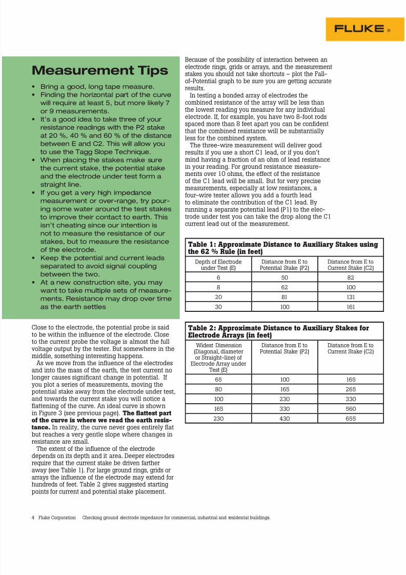
The Selective Method
The Selective Method is a variation o theFall-o-Potential method, available on high-endground testers like the Fluke 165. Testers withthis capability can measure the ground impedance
o a specic ground electrode without disconnect-ing it rom an array or rom a structure’s distribu-tion system. This means you don’t have to waitor a shutdown to test or risk the saety hazards o disconnecting the electrode rom a live system.
The same rules or current stake and potentialstake placement apply as with Fall-o-Poten-tial. I the conditions are met or the 6 % rule(see previous page) then it can help reduce thenumber o measurements. Otherwise it’s a goodidea to build a complete Fall-o-Potential plot. Youcan use the Tagg Slope Technique i your curvedoes not fatten out.
Both the Fall-o-Potential method and the
Selective Method use stakes to inject current andmeasure voltage drop. The big dierence is thatselective testing can accurately measure the testcurrent in the electrode under test.
The utility neutral, building steel and groundelectrode are all bonded and grounded. Whenyou inject a current into this system o paral-lel ground connections the current will divide.In a traditional Fall-o-Potential test you haveno way o knowing how much current is fow-
ing between anyparticular electrodeand the C currentstake. Selective
testing uses anintegrated, highsensitivity clamp-oncurrent transormerto measure thetest current in theelectrode undertest. Figure 8 showshow the currenttransormer ts intothe test circuit. Theselective groundtester digitallylters the currentmeasurement tominimize the eectso stray currents.Being able toaccurately measurethe current in theelectrode under testeectively isolatesthe electrode andallows us to testit without discon-necting it rom thesystem or romother electrodes.
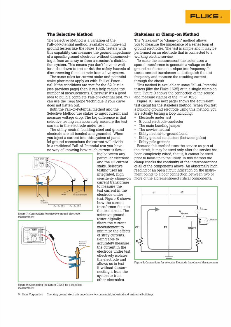
Stakeless or Clamp-on Method
The “stakeless” or “clamp-on” method allowsyou to measure the impedance o a series loop o ground electrodes. The test is simple and it may beperormed on an electrode that is connected to a
working electric service.To make the measurement the tester uses aspecial transormer to generate a voltage on theground conductor at a unique test requency. Ituses a second transormer to distinguish the testrequency and measure the resulting currentthrough the circuit.
This method is available in some Fall-o-Potentialtesters (like the Fluke 165) or in a single clamp onunit. Figure 9 shows the connection o the sourceand measure clamps o the Fluke 165.
Figure 10 (see next page) shows the equivalenttest circuit or the stakeless method. When you testa building ground electrode using this method, you
are actually testing a loop including:• Electrode under test• Ground electrode conductor• The main bonding jumper• The service neutral• Utility neutral-to-ground bond• Utility ground conductors (between poles)• Utility pole grounds
Because this method uses the service as part o the circuit, it may be used only ater the service hasbeen completely wired, that is, it cannot be usedprior to hook-up to the utility. In this method theclamp checks the continuity o the interconnectionso all o the components above. An abnormally high
reading or an open circuit indication on the instru-ment points to a poor connection between two ormore o the aorementioned critical components.
Figure 7: Connections or selective ground electrodemeasurement
Figure 8: Connections or selective Electrode Impedance Mesaurement
Figure 9: Connecting the Saturn GEO X or a stakelessmeasurement

8/6/2019 Checking Ground Impedance
http://slidepdf.com/reader/full/checking-ground-impedance 7/8
8/6/2019 Checking Ground Impedance
http://slidepdf.com/reader/full/checking-ground-impedance 8/8
8 Fluke Corporation Checking ground electrode impedance or commercial, industrial and residental buildings.
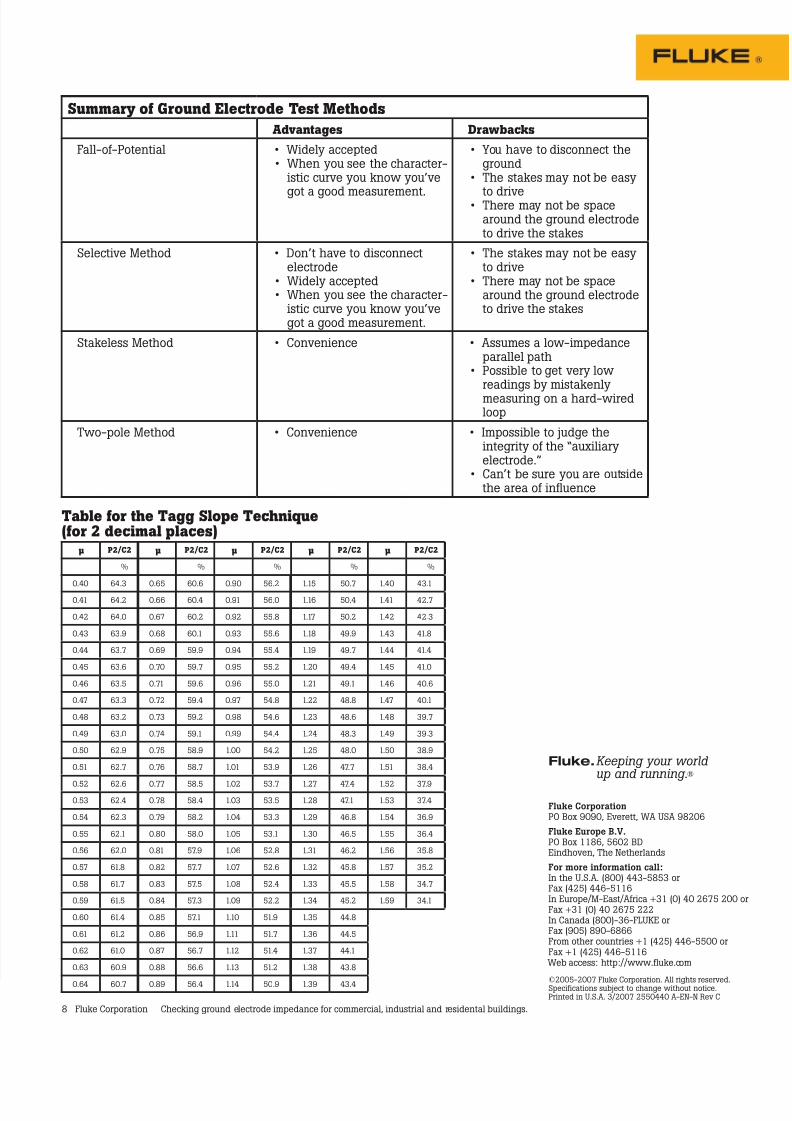
Summary o Ground Electrode Test Methods
Advantages Drawbacks
Fall-o-Potential • Widely accepted• When you see the character-
istic curve you know you’ve
got a good measurement.
• You have to disconnect theground
• The stakes may not be easy
to drive• There may not be spacearound the ground electrodeto drive the stakes
Selective Method • Don’t have to disconnectelectrode
• Widely accepted• When you see the character-
istic curve you know you’vegot a good measurement.
• The stakes may not be easyto drive
• There may not be spacearound the ground electrodeto drive the stakes
Stakeless Method • Convenience • Assumes a low-impedanceparallel path
• Possible to get very lowreadings by mistakenlymeasuring on a hard-wiredloop
Two-pole Method • Convenience • Impossible to judge theintegrity o the “auxiliaryelectrode.”
• Can’t be sure you are outsidethe area o infuence
Table or the Tagg Slope Technique(or 2 decimal places)
0.40 64.
0.41 64.
0.4 64.0
0.4 6.9
0.44 6.7
0.45 6.6
0.46 6.5
0.47 6.
0.48 6.
0.49 6.0
0.50 6.9
0.51 6.7
0.5 6.6
0.5 6.4
0.54 6.
0.55 6.1
0.56 6.0
0.57 61.8
0.58 61.7
0.59 61.5
0.60 61.4
0.61 61.
0.6 61.0
0.6 60.9
0.64 60.7
0.65 60.6
0.66 60.4
0.67 60.
0.68 60.1
0.69 59.9
0.70 59.7
0.71 59.6
0.7 59.4
0.7 59.
0.74 59.1
0.75 58.9
0.76 58.7
0.77 58.5
0.78 58.4
0.79 58.
0.80 58.0
0.81 57.9
0.8 57.7
0.8 57.5
0.84 57.
0.85 57.1
0.86 56.9
0.87 56.7
0.88 56.6
0.89 56.4
0.90 56.
0.91 56.0
0.9 55.8
0.9 55.6
0.94 55.4
0.95 55.
0.96 55.0
0.97 54.8
0.98 54.6
0.99 54.4
1.00 54.
1.01 5.9
1.0 5.7
1.0 5.5
1.04 5.
1.05 5.1
1.06 5.8
1.07 5.6
1.08 5.4
1.09 5.
1.10 51.9
1.11 51.7
1.1 51.4
1.1 51.
1.14 50.9
1.15 50.7
1.16 50.4
1.17 50.
1.18 49.9
1.19 49.7
1.0 49.4
1.1 49.1
1. 48.8
1. 48.6
1.4 48.
1.5 48.0
1.6 47.7
1.7 47.4
1.8 47.1
1.9 46.8
1.0 46.5
1.1 46.
1. 45.8
1. 45.5
1.4 45.
1.5 44.8
1.6 44.5
1.7 44.1
1.8 4.8
1.9 4.4
1.40 4.1
1.41 4.7
1.4 4.
1.4 41.8
1.44 41.4
1.45 41.0
1.46 40.6
1.47 40.1
1.48 9.7
1.49 9.
1.50 8.9
1.51 8.4
1.5 7.9
1.5 7.4
1.54 6.9
1.55 6.4
1.56 5.8
1.57 5.
1.58 4.7
1.59 4.1
µ P2/C2
%
µ P2/C2
%
µ P2/C2
%
µ P2/C2
%
µ P2/C2
%
Fluke Corporation PO Box 9090, Everett, WA USA 9806
Fluke Europe B.V. PO Box 1186, 560 BDEindhoven, The Netherlands
For more information call: In the U.S.A. (800) 44-585 orFax (45) 446-5116In Europe/M-East/Arica +1 (0) 40 675 00 orFax +1 (0) 40 675 In Canada (800)-6-FLUKE orFax (905) 890-6866From other countries +1 (45) 446-5500 orFax +1 (45) 446-5116
Web access: http://www.luke.com
©005-007 Fluke Corporation. All rights reserved.Speciications subject to change without notice.Printed in U.S.A. /007 550440 A-EN-N Rev C
Fluke.Keeping your world up and running.®