Embed Size (px)
Citation preview
Page 1 5/2/2013
CCHHEEMMIISSTTRRYY 111122 LLEECCTTUURREE EXAM II Material
Part I Chemical Bonding I – Lewis Theory Chapter 9 pages 376-386 A. Drawing electron dot structures HOW TO: 1. Write e- dot structure for the individual atoms.
2. a) Add together the number of valence electrons for all the atoms (If it is an ion, you must add or subtract electrons accordingly)
b) Divide the total number of e- by 2: This will give you the number of e- pairs available for bonding.
3. Determine which is the central atom a. The least represented atom that is not H
b. Usually, the first atom in the chemical formula that is not H.
4. Arrange atoms symmetrically around the central atom.
5. Draw a single line (or 2 dots) between the central and outer atoms.
6. From the total number of valence electrons subtract 2 electron for each bond made.
7. Attempt to place the remaining electron pairs around the outer atoms to make an octet
or duet (for H)
8. Additional electrons are placed on the central atom
9. If the central atom still has less than an octet ; then, a double or triple bond must be formed. Do not use a double or triple bond unless you have to!
, a general rule(a help) Examples:
B. Specific Electron Dot Cases: 1. Ions: 2. Oxy Acids 3. Carbon chains

Page 2 5/2/2013
C. Exceptions to the Octet Rule 1. Electron deficient molecules: Molecules where the central atom does not have an octet. Usually a group IIIA atom Example: BCl3
2. Expanded valence shell: Molecules where the central atom has more than 8 valence around the central atom.
The central atom would belong to the 3rd, 4th,5th,6th,or 7thperiod. Example: SF6
3. Molecules with an odd number of electrons: There are an odd number of valence electrons in the molecule Example: NO2
Page 3 5/2/2013
Practice:
SO2
IF5
NO3-
HBrO
CH3COCH3
PF5
H3O+
SO3
CH2O
H3PO4
SCl2
CO
OH-
SO32-
HClO
CO32-
IOCl5 IF3
XeCl2
NF3+
BH3 H2PO3
-
Page 4 5/2/2013
Part II Resonance Structures
Some molecules can be drawn with more than one lewis dot structure.
None of the lewis dot structure depicts the molecule accurately. Resonance structures are two or more electron dot structures for a molecule or ion that have the same arrangement of atoms. Ozone:
Experiments have shown that the two lewis dot structures are equivalent and that the bond strength characteristics are
a hybrid of the two structures. The actual molecule is a resonance hybrid with two of the electrons being
delocalized (spread over the entire molecule).
Examples: 1.. Given: NO3
1-
2. Given: SCN1-
Page 5 5/2/2013
Part III Formal Charges The Formal Charge of an atom is the hypothetical charge you obtain by assuming that the bonding electrons are equally shared. Formal charges, when assigned, can be used to determine the most important lewis dot structure.
Formal Charge How To : 1. All of the unshared (nonbonding) electrons are assigned to the atom on which they are found
2. Half of the bonding electrons are assigned to each atom in the bond.
Formal Charge = valence electrons - unshared valence electrons - 1/2 shared electrons]
Selection of the most important lewis structure:
1. Smaller formal charges (+ or -) are better than larger formal charges
2. like charges on adjacent atoms are not desirable
3. The more negative formal charge should be assigned to the more electronegative atom. Practice Problem: NNO
Page 6 5/2/2013
Part IV Chemical Bonding II: Molecular Shapes, Valence Bond Theory, and Molecular Orbital Theory Chapter 9 & 10
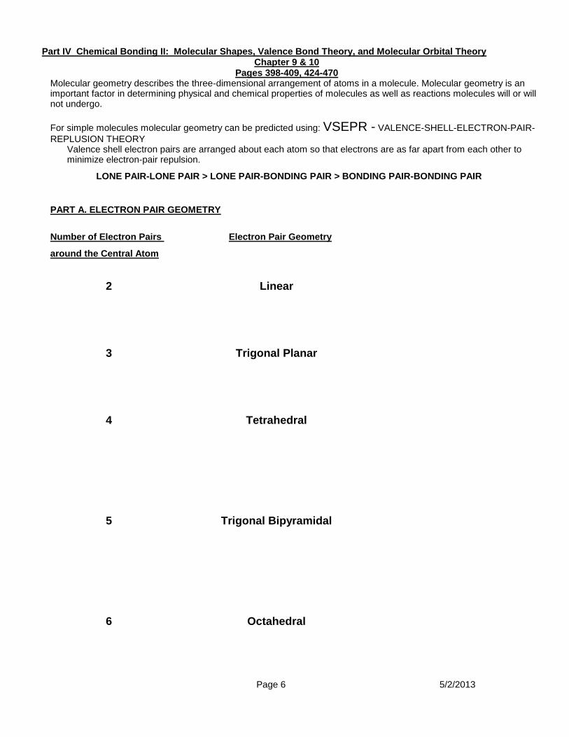
Pages 398-409, 424-470 Molecular geometry describes the three-dimensional arrangement of atoms in a molecule. Molecular geometry is an important factor in determining physical and chemical properties of molecules as well as reactions molecules will or will not undergo.
For simple molecules molecular geometry can be predicted using: VSEPR - VALENCE-SHELL-ELECTRON-PAIR-
REPLUSION THEORY Valence shell electron pairs are arranged about each atom so that electrons are as far apart from each other to minimize electron-pair repulsion.
LONE PAIR-LONE PAIR > LONE PAIR-BONDING PAIR > BONDING PAIR-BONDING PAIR
PART A. ELECTRON PAIR GEOMETRY
Number of Electron Pairs Electron Pair Geometry
around the Central Atom
2 Linear
3 Trigonal Planar
4 Tetrahedral
5 Trigonal Bipyramidal
6 Octahedral
Page 7 5/2/2013
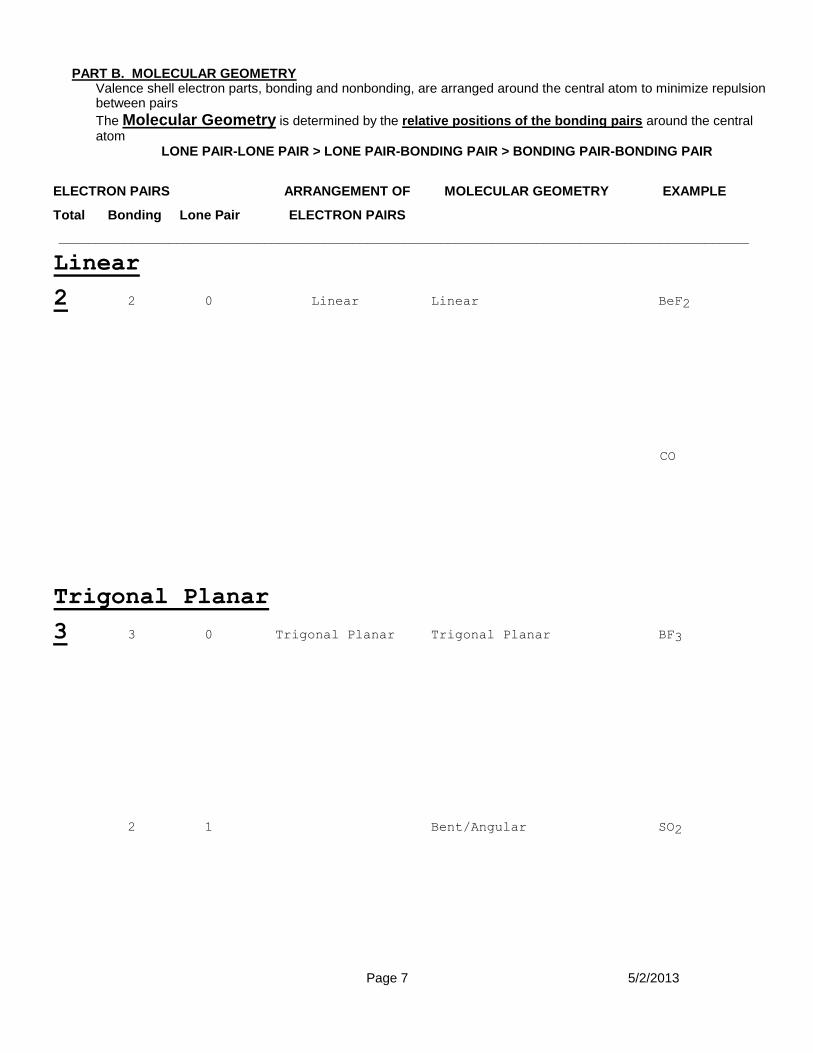
PART B. MOLECULAR GEOMETRY Valence shell electron parts, bonding and nonbonding, are arranged around the central atom to minimize repulsion between pairs
The Molecular Geometry is determined by the relative positions of the bonding pairs around the central atom
LONE PAIR-LONE PAIR > LONE PAIR-BONDING PAIR > BONDING PAIR-BONDING PAIR
ELECTRON PAIRS ARRANGEMENT OF MOLECULAR GEOMETRY EXAMPLE
Total Bonding Lone Pair ELECTRON PAIRS
______________________________________________________________________________________________
Linear
2 2 0 Linear Linear BeF2
CO
Trigonal Planar
3 3 0 Trigonal Planar Trigonal Planar BF3
2 1 Bent/Angular SO2
Page 8 5/2/2013
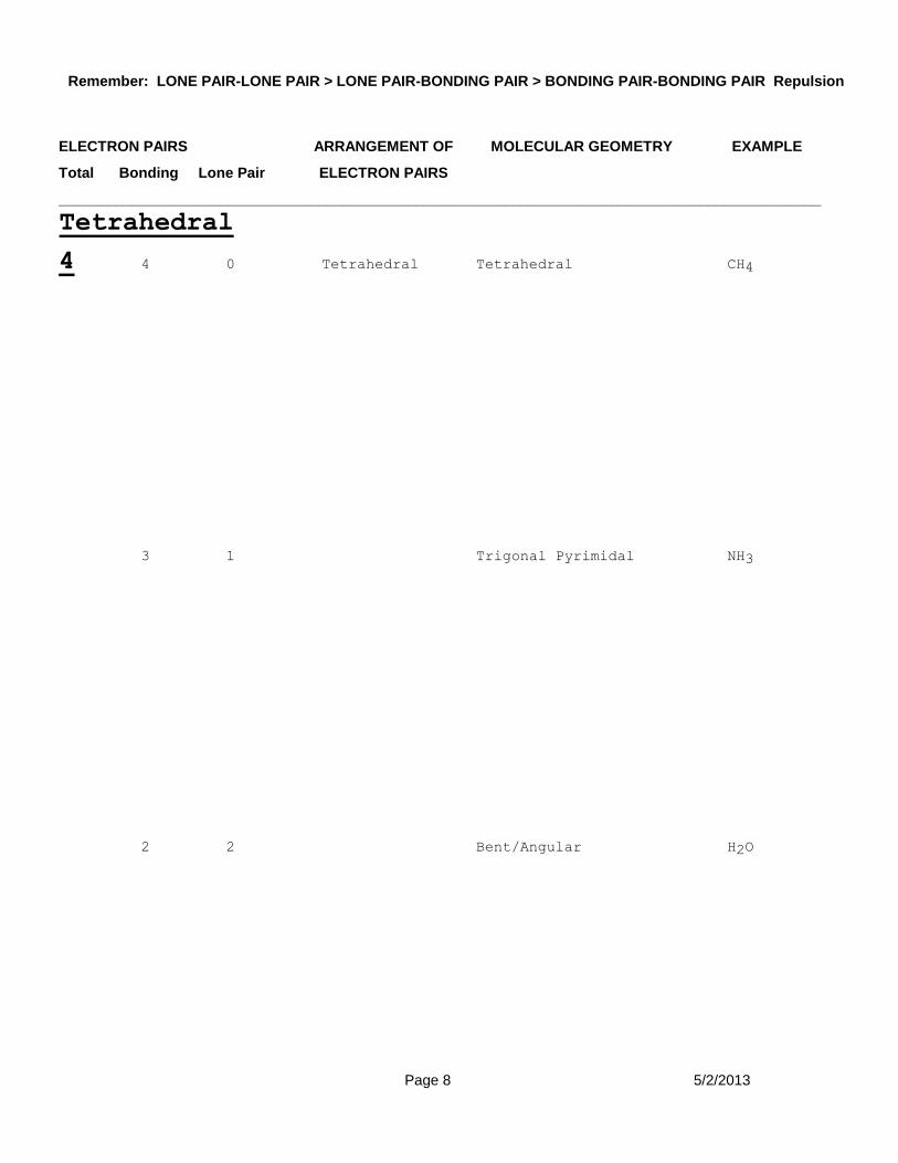
Remember: LONE PAIR-LONE PAIR > LONE PAIR-BONDING PAIR > BONDING PAIR-BONDING PAIR Repulsion
ELECTRON PAIRS ARRANGEMENT OF MOLECULAR GEOMETRY EXAMPLE
Total Bonding Lone Pair ELECTRON PAIRS
______________________________________________________________________________________________
Tetrahedral
4 4 0 Tetrahedral Tetrahedral CH4
3 1 Trigonal Pyrimidal NH3
2 2 Bent/Angular H2O

Page 9 5/2/2013
Remember: LONE PAIR-LONE PAIR > LONE PAIR-BONDING PAIR > BONDING PAIR-BONDING PAIR Repulsion
ELECTRON PAIRS ARRANGEMENT OF MOLECULAR GEOMETRY EXAMPLE
Total Bonding Lone Pair ELECTRON PAIRS
_______________________________________________________________________________________________
Trigonal Bipyramidal
5 5 0 Trigonal Bipyramidal Trigonal Bipyramidal PCl5
4 1 Seesaw/Distorted SF4
Tetrahedron
3 2 T-shaped ClF3
2 3 Linear XeF2
Page 10 5/2/2013
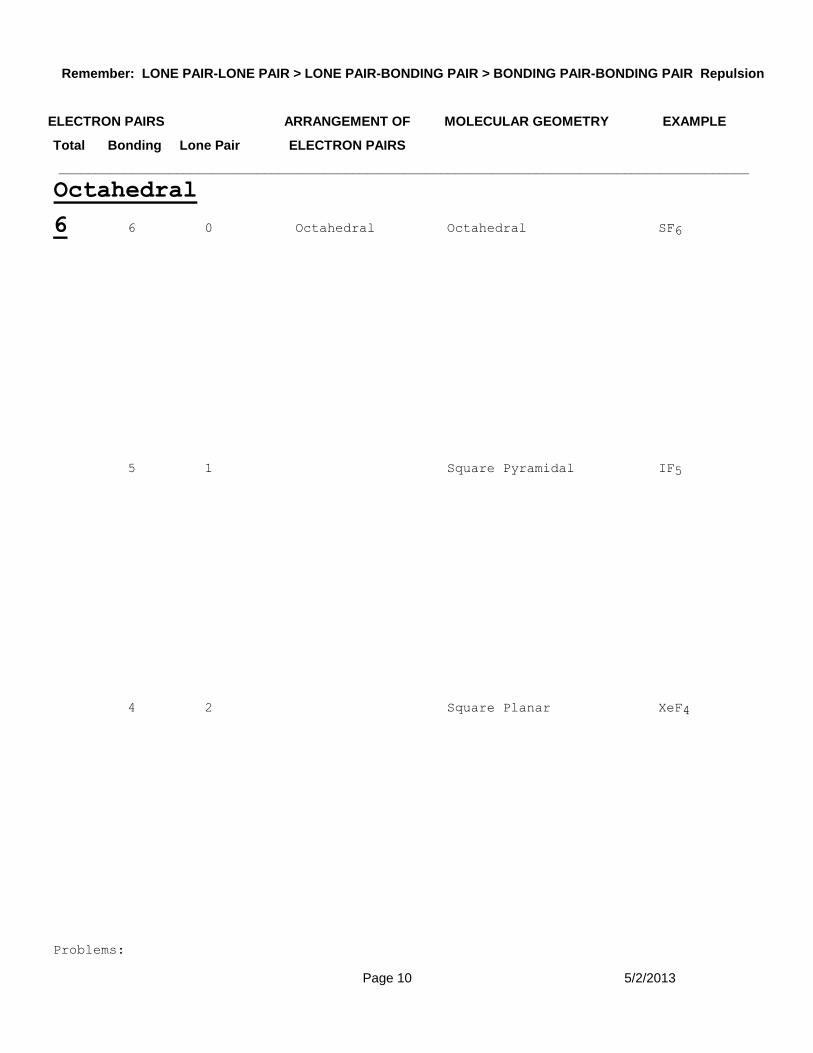
Remember: LONE PAIR-LONE PAIR > LONE PAIR-BONDING PAIR > BONDING PAIR-BONDING PAIR Repulsion
ELECTRON PAIRS ARRANGEMENT OF MOLECULAR GEOMETRY EXAMPLE
Total Bonding Lone Pair ELECTRON PAIRS
______________________________________________________________________________________________
Octahedral
6 6 0 Octahedral Octahedral SF6
5 1 Square Pyramidal IF5
4 2 Square Planar XeF4
Problems:
Page 11 5/2/2013
Give the Molecular Geometry for the following:
1. CO32-
2. O3
3. AsF5
4. IOF5
5. BrF3
6. SO42-
7. H3O
+
8. OF2
9. XeO2F2
10. ICl4-
11. I3-
12. TeF5-
13. HSO31-

Page 12
BACKGROUND Quantum mechanics can be used to understand bonding and electronic structure. We will
consider two theories derived from quantum mechanics: Valence Bond Theory (VB) and
Molecular Orbital Theory (MO). Both theories use quantum mechanics but use different
simplifying assumptions
PART I VALENCE BOND THEORY: Orbital Overlap as a Chemical Bond
According to Valence Bond Theory (VB) A bond forms between two atoms when orbitals
(electron clouds) overlap and a pair of electrons occupies the region between both
nuclei.
The following conditions must be met:
1. There must be maximum overlap in a region between the two nuclei of the bonding
atoms.
2. The total number of electrons in the same region of space (overlap) is no more
than two. According the Pauli Exclusion Principle, the two electrons must have
opposite spin.
Page 13
A. HYBRID ORBITALS
To apply the Valence Bond theory to polyatomic molecules both the
formation of electron-pair bonds (shared electrons) and the observed
geometries of the molecules must be shown.
1. The number of hybrid orbitals obtained always equals the number of
atomic orbitals mixed
2. The type of hybrid orbitals obtained varies with the types of atomic
orbitals mixed.

Page 14
sp Hybrid Orbitals
1. Linear/180°
2. 2 Hybrid orbitals from the hybridization of one “s” and one “p”
orbital
Consider BeF2:
Energy Diagram/Electron Box Diagram:
Ground State Excited State Bonded state
(Central atom) (Central atom) in molecule
Contour Diagram:
+
=
Hybridize
s orbital p orbital Two sp hybrid orbitals
sp hybrid orbitals shown together (large lobes only)
Page 15
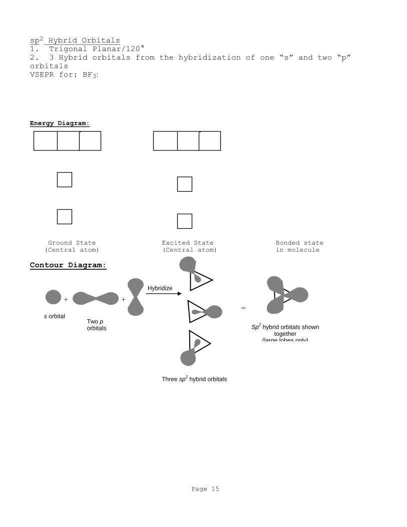
sp2 Hybrid Orbitals
1. Trigonal Planar/120°
2. 3 Hybrid orbitals from the hybridization of one “s” and two “p”
orbitals
VSEPR for: BF3:
Energy Diagram:
Ground State Excited State Bonded state
(Central atom) (Central atom) in molecule
Contour Diagram:
+ +
=
Three sp
2 hybrid orbitals
Hybridize
s orbital Two p orbitals
Sp
2 hybrid orbitals shown
together (large lobes only)

Page 16
sp3 Hybrid Orbitals
1. Tetrahedral/109.5°
2. 4 Hybrid orbitals from the hybridization of one “s” and three “p”
orbitals
VSEPR for: CH4
Energy Diagram:
Ground State Excited State Bonded state
(Central atom) (Central atom) in molecule
Contour Diagram:
z z z z
y y y y
x x x x
s px Py Pz Hybridize to form four sp
3 hybrid orbitals
+ + +
Shown together (large lobes only)
sp
3
sp
3
sp
3
sp
3
sp
3 sp
3 sp
3 sp
3
109.5°
Page 17
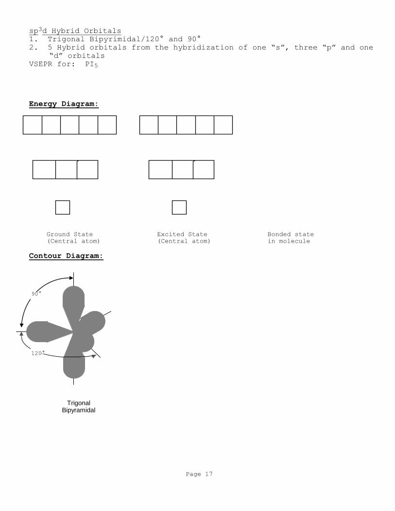
sp3d Hybrid Orbitals
1. Trigonal Bipyrimidal/120° and 90°
2. 5 Hybrid orbitals from the hybridization of one “s”, three “p” and one
“d” orbitals
VSEPR for: PI5
Energy Diagram:
Ground State Excited State Bonded state
(Central atom) (Central atom) in molecule
Contour Diagram:
90°
120°
Trigonal Bipyramidal

Page 18
sp3d2 Hybrid Orbitals
1. Octahedral/ 90°
2. 6 Hybrid orbitals from the hybridization of one “s”, three “p” and two
“d” orbitals
VSEPR for: SBr6
Energy Diagram:
Ground State Excited State Bonded state
(Central atom) (Central atom) in molecule
Contour Diagram:
90
°
90°
Octahedral
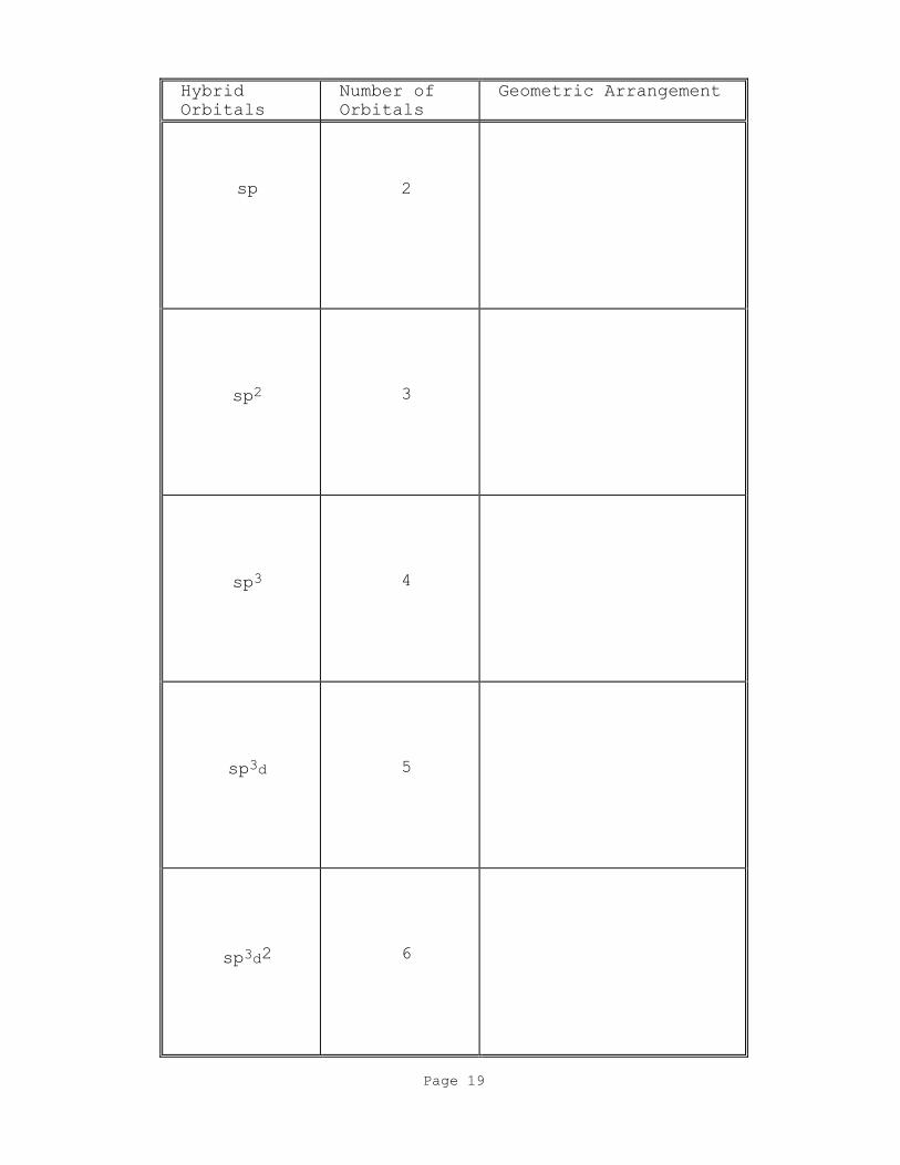
Page 19
Hybrid
Orbitals
Number of
Orbitals
Geometric Arrangement
sp
2
sp2
3
sp3
4
sp3d
5
sp3d2
6
Page 20
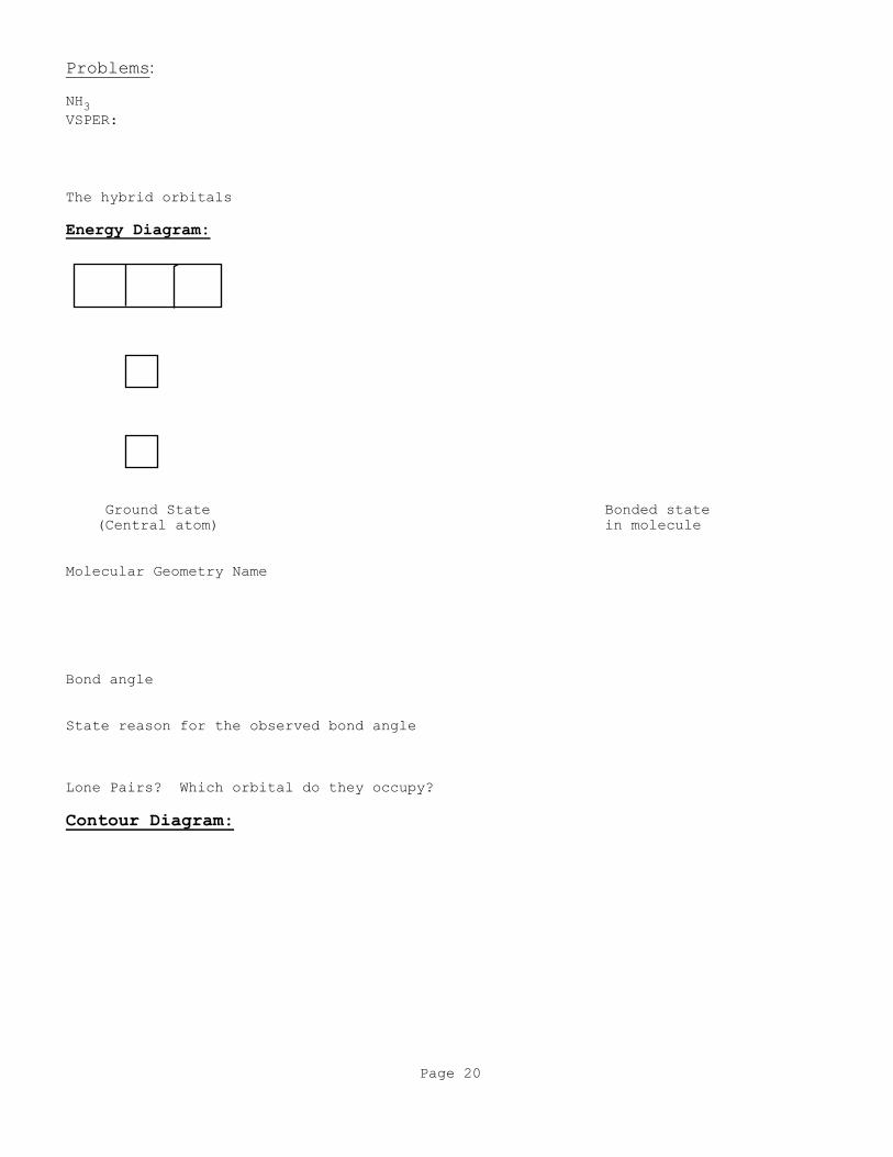
Problems:
NH3
VSPER:
The hybrid orbitals
Energy Diagram:
Ground State Bonded state
(Central atom) in molecule
Molecular Geometry Name
Bond angle
State reason for the observed bond angle
Lone Pairs? Which orbital do they occupy?
Contour Diagram:

Page 21
H2O
VSEPR:
The hybrid orbitals
Energy Diagram:
Ground State Excited State Bonded state
(Central atom) (Central atom) in molecule
Molecular Geometry name
Bond angle
State reason for the observed bond angle
Lone Pairs? Which orbital do they occupy?
Contour Diagram

Page 22
ClF3
VSEPR:
The hybrid orbitals
Energy Diagram:
Ground State Excited State Bonded state
(Central atom) (Central atom) in molecule
Molecular Geometry Name
Bond angle
State reason for the observed bond angle
Lone Pairs? Which orbital do they occupy?
Contour Diagram:
Page 23
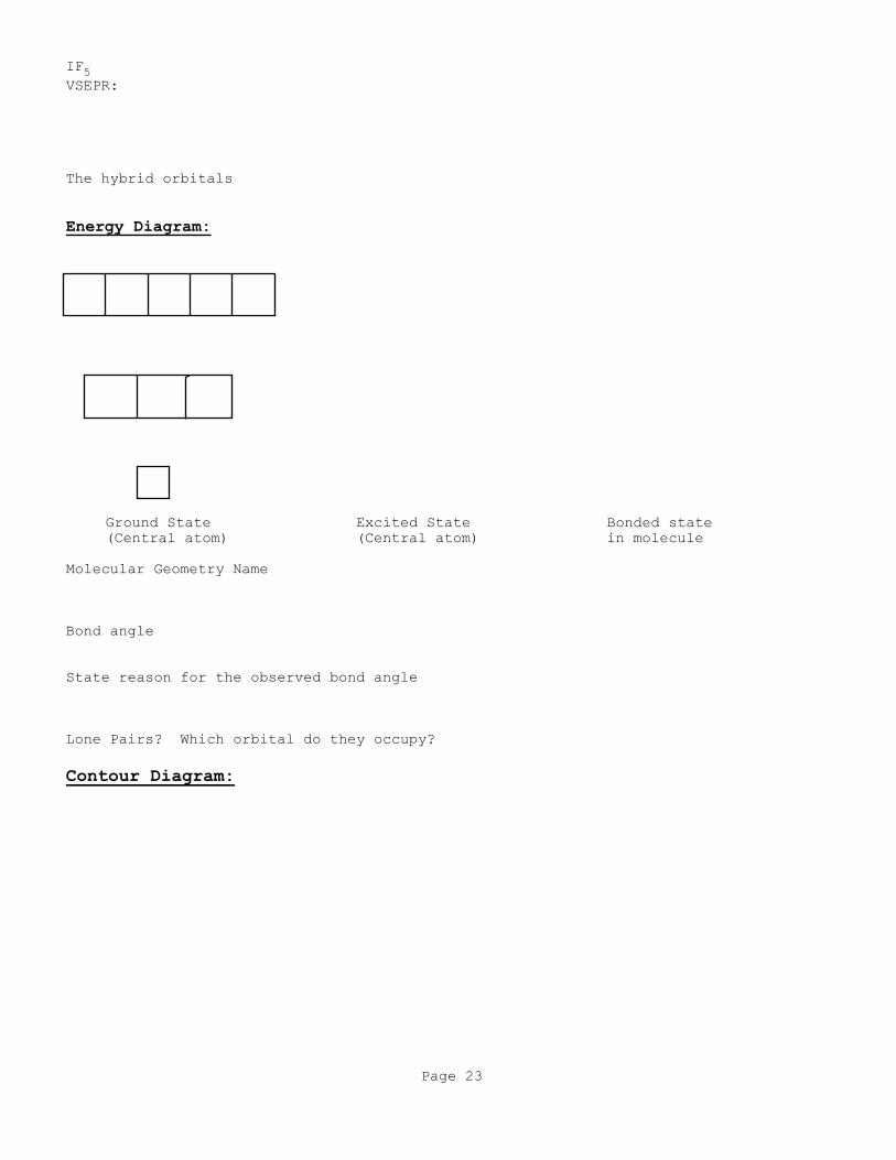
IF5
VSEPR:
The hybrid orbitals
Energy Diagram:
Ground State Excited State Bonded state
(Central atom) (Central atom) in molecule
Molecular Geometry Name
Bond angle
State reason for the observed bond angle
Lone Pairs? Which orbital do they occupy?
Contour Diagram:
Page 24
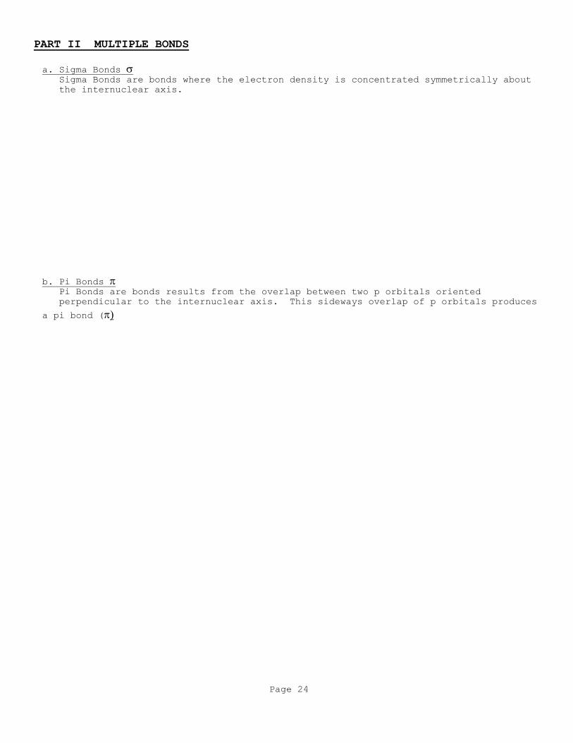
PART II MULTIPLE BONDS
a. Sigma Bonds Sigma Bonds are bonds where the electron density is concentrated symmetrically about
the internuclear axis.
b. Pi Bonds Pi Bonds are bonds results from the overlap between two p orbitals oriented
perpendicular to the internuclear axis. This sideways overlap of p orbitals produces
a pi bond (

Page 25
Use the Valence Bond Theory to explain the bonding in C2H4
VSEPR:
The hybrid orbitals
Energy diagram:
Ground State Excited State Bonded state
(Central atom) (Central atom) in molecule
Molecular Geometry Name
Bond angle
Lone Pairs? Which orbital do they occupy?
Use the Valence Bond Theory to explain the bonding in C2H2
VSEPR:
Page 26
The hybrid orbitals
Electron box diagram
Ground State Excited State Bonded state
(Central atom) (Central atom) in molecule
Molecular Geometry Name
Bond angle
Lone Pairs? Which orbital do they occupy?

Page 27
Double Bonds
Triple Bonds

Page 28
VBT problems
For the following compounds:
a. Give the VSEPR structure
b. Determine the hybridization of the central atom
c. Draw the electron box diagram, fully labeled
d. Draw the VBT contour diagrams, fully labeled
(include bond angles, also)
1. BH3
2. ICl3
3. C2Cl2
4. AsI5
5. PH3
6. SI6
7. H2Se
8. H2Se
9. FCCF
10. ClBr2F
11. BrI5
12. Br2CCBr2
13. SiN-
14. NCl3
15. NCl3
16. NO2

Page 29
PART III MOLECULAR ORBITAL THEORY (MO): Electron Delocalization Pages 458-470
In the molecular orbital theory electrons in molecules exists in allowed
energy states called molecular orbitals. The MO theory views the entire
molecular orbitals extending over the entire molecule.
Background:
Addition of waves
Page 30
The Hydrogen Molecule:
When the two separate atomic orbitals from each hydrogen over lap two
molecular orbitals are produced.
The higher energy orbital has none/very
little electron density between the nuclei
and is called the antibonding orbital
The lower energy orbital concentrates its
electron density between the two hydrogen
nuclei and is called the bonding orbital
BOND ORDER = 1
2 ( # Bonding electrons - # Antibonding electrons )
A bond order of = 1 is a single bond
A bond order of = 2 is a double bond
A bond order of = 3 is a triple bond
Note: With this theory bond orders of 1/2,3/2 and etc can occur
Electron Configuration:
Page 31
(MO style!)

Page 32
Draw the Molecular Orbital Energy level diagram for the following:
(First Row) He2
a. Bond Order:
b. Number of unpaired electrons and magnetic properties
He2+
a. Bond Order:
b. Number of unpaired electrons and magnetic properties

Page 33
Molecular Orbital (MO) Energy-Level Diagrams
1. The number of molecular orbitals formed always equals the number of
atomic orbitals combined.
2. Atomic orbitals combine into Molecular Orbitals most effectively with
other atomic orbitals of similar energy.
3. The effectiveness of the atomic orbitals combining into molecular
orbitals is dependent on the amount of overlap of the orbitals. As
the overlap increases, the bonding orbital energy (ex 1s) is lowered
and the antibonding (ex. *1s) is raised in energy.
4. Each molecular orbital can have a maximum of two electrons with paired
spins (Pauli exclusion principle)
5. When Molecular orbitals have the same energy (degenerate), one
electron enters each separate orbital (with the same spin-Hunds rule!)
before spin pairing occurs.
Contour representations of molecular orbitals formed by by the 2p orbitals
on two atoms.
Page 34
2nd Row Elements - p orbitals
MO Energy Level Diagram for homonuclear diatomic molecules
Draw the Molecular Orbital Energy level diagram for F2
- Small 2s-2px interaction
a. Electron Configuration:
b. Bond Order:
c. Number of unpaired electrons and magnetic properties:
d. Bond Length:
e. Bond Dissociation Energy:
f. Bond Strength:
Page 35
Draw the Molecular Orbital Energy level diagram for O2 - Small 2s-2px interaction
a. Electron Configuration:
b. Bond Order:
c. Number of unpaired electrons and magnetic properties:
d. Bond Length
e. Bond Dissociation Energy:
f. Bond Strength:
g. Compare the O2 molecule to O22- ion
h. Compare the O2 molecule to O21+
Page 36
Draw the Molecular Orbital Energy level diagram for N2
- Large 2s-2px interaction
a. Electron Configuration:
b. Bond Order:
c. Number of unpaired electrons and magnetic properties:
d. Bond Length
e. Bond Dissociation Energy:
f. Bond Strength:

Page 37
MO Energy Level Diagram for a Heteronuclear diatomic molecules
Draw the Molecular Orbital Energy level diagram for CN- (If similar to a
homonuclear diatomic molecule
- Large 2s-2px interaction
a. Electron Configuration:
b. Bond Order:
c. Number of unpaired electrons and magnetic properties:
d. Bond Length
e. Bond Dissociation Energy:
f. Bond Strength:
Page 38
Problems:
1. Which has the Highest Bond Energy? Why?
a. B2 or B22+
b. C2 or C22-
2. Which has the Shortest Bond Length? Why?
a. Ne2 or Ne2-
b. F2 or F2+1
3. Which has the Lowest Bond Dissociation Energy? Why?
a. C2 or C22-
b. C2 or C22-