Embed Size (px)
Citation preview

CHEETAH End-Host Software Design Specification
1. Introduction
1.1 Goals and Objectives
CHEETAH end-host software is a part of our effort to develop the infrastructure and networking technologies to support a
broad class of eScience projects and specifically the Terascale Supernova Initiative (TSI) [1]. The objectives of this work are
to design and deploy a high-performance, experimental optical network infrastructure and to test application/middleware/
transport protocol software, developed specifically for eScience projects, on this network. Our two target applications are file
transfers and remote visualization.
To meet the needs of those large-scale eScience project, we propose an end-to-end optical networking solution called Cir-
cuit-switched High-speed End-to-End Transport ArcHitecture (CHEETAH) [2]. In this solution, high-speed optical circuits,
consisting of a hybrid of high-speed Ethernet signals from/to end hosts within LANs and equivalent-rate Ethernet-over-
SONET (EoS) circuits across the wide area, are set up and released dynamically. Once a circuit is established, large files can
simply be streamed unhindered resulting in low file transfer delays. Furthermore, there is almost no variation in the delays
experienced by different data blocks sent over a circuit. Bit error rates on optical links are low, requiring few retransmissions if
any. Therefore, low end-to-end latency and jitter guarantees are possible in this networking solution.
To take advantage of the benefits brought by the CHEETAH service, software enhancements are needed at end hosts. This
enhancement addresses research questions in the various components of networking work, e.g. Internetworking between dif-
ferent types of networks, transport protocols for dedicated end-to-end circuits, GMPLS-driven circuit provisioning, routing,
etc. This document is a detailed design document for an implementation of the CHEETAH end-host software.
1.2 Assumptions and Constraints
The CHEETAH software discussed in this document is limited to the implementation on general-purposed computers (end
hosts). Any discussion about network elements other than general-purposed end hosts is beyond the scope of this documenta-
tion.
1.3 Development Methods
The current CHEETAH end-host software is developed using C/C++ and Java on Linux platform. The Win32 version will

be developed later.
2. System Overview and System Architecture
An overview of the end-host CHEETAH software architecture is shown in Figure 11. We identify six basic modules for the
CHEETAH end-host software: a Optical Connectivity Service (OCS) module, a Authentication, Authorization and Accounting
(AAA) module, a router disconnect module, a routing decision module, a RSVP-TE signaling module, and a high-speed trans-
port protocol (FRTP) module.
2.1 The functionality of each module
OCS module: Determine whether the correspondent end host can be reached by a direct end-to-end CHEETAH circuit
through circuit-switched network. OCS is important to enable a gradual growth of CHEETAH users. If an end host with
CHEETAH capability wants to communicate with an end host without such capability, it will simply use the Internet. If,
through OCS, it determines that the correspondent host also has CHEETAH capability, and furthermore it is connected via the
same optical circuit-switched network, it can use a CHEETAH circuit.
AAA module: Authenticate users, handle authorization requests, and collect accounting data.
Router disconnect module: To allow for end-to-end CHEETAH circuits to be established, an enterprise needs to lease a
1. CHEETAH End-host hardware configuration requires a secondary Ethernet NICs in end hosts, which are accessible through CHEE-TAH circuit-switched network.
TCP NIC I
NIC II
FRTPPrimary TCP/
IP path
End-to-end CHEETAH circuit
SFTPWeb
service
Videotelephony
Signaling
End-host CHEETAHsoftware
Routingdecision
OCS/AAA
RouterDisconnect
Figure 1. End-host CHEETAH software architecture

optical circuit to the service provider’s optical circuit-switched network. It would be a waste to let this high-speed circuit lie
unused when there is no CHEETAH communication. Hence we propose a scheme in which such leased circuits could be used
to interconnect enterprise IP routers with IP routers on Internet2, ESnet or the Internet itself, until a CHEETAH request
appears. When it does, this router-to-router circuit is torn down by router disconnect module and the CHEETAH circuit is
established for the duration of the session.
Routing decision module: For communication between two entities that can be connected by a direct CHEETAH circuit,
there is a choice of two paths: the primary TCP/IP path and an Ethernet/SONET circuit. The presence of two such paths raises
the question of which path an end-host application should choose. We recognize that it is not appropriate to attempt a circuit
setup for all communication sessions. For example, for a small-file transfer (file size is on the order of a few KB), the total
delay incurred in setting up a circuit and then transferring the file could be larger than the delay incurred in directly using the
TCP/IP path. Thus, a routing decision needs to be made at end hosts with access to RESCUE.
Signaling module: Initiate a call-setup request to the signaling-enabled network switches according to the GMPLS signal-
ing standards.
Transport protocol module: For the actual data transfer on CHEETAH circuits, we recommend using a combination of a
rate-based transport protocol on the unidirectional end-to-end Ethernet/SONET circuit from the server to the client and a TCP
connection for the reverse direction through the IP network. Standard TCP is not well-suited for end-to-end circuits [3], i.e.,
paths on which there are no packet switches, because of the congestion-control mechanisms built into Standard TCP. This
functionality is not only unnecessary if the end-to-end path is a circuit, it is also detrimental because bit errors will be inter-
preted as congestion losses causing variations in the sending rate. For full utilization of the circuit what we need is a transport
protocol that uses rate-based flow control and constantly sends data.
2.2 The work flow of end-host CHEETAH software
The user application (can be either SFTP, web application, or videotelephony, etc.) shown in Figure 1 first calls OCS mod-
ule to determine if the remote host has CHEETAH capability. If the remote end host does not have such a capability, the user
application will simply use the Internet through the end host’s primary NIC. If, through OCS, it determines that the correspon-
dent host also has CHEETAH capability, and furthermore it is connected via the same optical circuit-switched network, it call
AAA module to authenticate the user and password and authorize user’s circuit setup request (AAA module will also record

user’s billing information if the later circuit setup is successful.). If the user successfully obtains the authentication and autho-
rization from AAA module, it calls routing decision module to decide whether or not to attempt a circuit setup. If routing deci-
sion module decides to attempt a circuit setup, the CHEETAH signaling module initiates a call-setup request to the signaling-
enabled network switches. If the circuit setup is successful, CHEETAH software will direct the user application to initiate data
transfers on the dedicated CHEETAH circuit through the end host’s secondary NIC. Depending upon the application, TCP or
some other transport protocols could be used on the circuit. If, on the contrary, the routing decision module determines the pri-
mary TCP/IP path is preferred, or if the circuit setup fails with signaling module, the user application will be directed to the
primary TCP/IP path through the end host’s primary NIC.
3. Detailed System Design
3.1 Optical Connectivity Service (OCS) module
3.1.1 Definition and Responsibilities
Definitions: OCS module includes a daemon running on a server and a client program on CHEETAH end hosts. The OCS
sever has a database which stores the connectivity information of CHEETAH end hosts (clients), i.e. whether an end host has
the CHEETAH access capability. The OCS is a distributed system. One OCS server can query other OCS servers if the infor-
mation could not be obtained locally.
Responsibilities: The OCS client program on the end hosts sends out OCS query messages to OCS servers when the user
application requires communication with other end hosts. The OCS server accepts query from CHEETAH client and responses
with an answer.
Constraints: The database maintained by OCS servers must be configured manually. Each end host has a corresponding
TXT type Resource Record (RR) in the local OCS server database. A string like “OCS available” needs to be added to the RR
for each end host with OCS capability. You can ask your OCS administrator to add this RR in the local OCS database for each
host which has the OCS capability.
3.1.2 Uses/Interactions
From the client (end host) side, a OCS program called NSLOOKUP can be called to send query to the OCS server, examin-
ing if the remote host has the string “OCS available” in its RR. If it has, then the remote host can be reached by CHEETAH.
NSLOOKUP is a popular shell command that comes with almost all the operating system, such as Windows, Unix, and Linux.

NSLOOKUP can also be found in BIND installation package. The parameters of NSLOOKUP are set as following:
> nslookup ®Ctype=TXT hostname
3.1.3 Detailed Subsystem Design
The OCS server can be realized in a similar way as the Domain Name System (DNS). DNS is a hierarchical, distributed
database that provides directory services. It stores information for mapping Internet host names to IP addresses and vice versa,
mail routing information, and other data used by Internet applications. Clients look up information in the DNS by calling a
resolver library, which sends queries to one or more name servers and interprets the responses. By mimic the DNS, in OCS, a
client can find whether the remote client has the CHEETAH connectivity available or not, before it starts to signal the CHEE-
TAH circuit setup.
In this document, the OCS server is setup according to the Domain Name System (DNS) structure and configurations. For
convenience, we use the DNS terminology in the following description.
The DNS name server does not require the high-end computers. In our case, a normal PC with Intel-486 processor (which is
required for BIND 9) can do the work. The hardware connectivity is shown in Figure 2. The DNS name server is connected to
Cisco 12000 series router and the router is connected to SONET cloud through the leased line. Please note, in the beginning of
the CHEETAH network, i.e. in the experimental period, a separated Name Server can be omitted for simplicity. In stead, the
Name Server function can be resided within the host machine.
Cisco MSPP 15454
Connect to primary 10/100M NIC Connect to secondary GbE NIC for uplink Connect tothird10/100MNICfordownlink
Internet
OC-48c linksCHEETAH circuit
Cisco12000router DNS Name Server
SONET cloud
Figure 2. OCS server in Cheetah
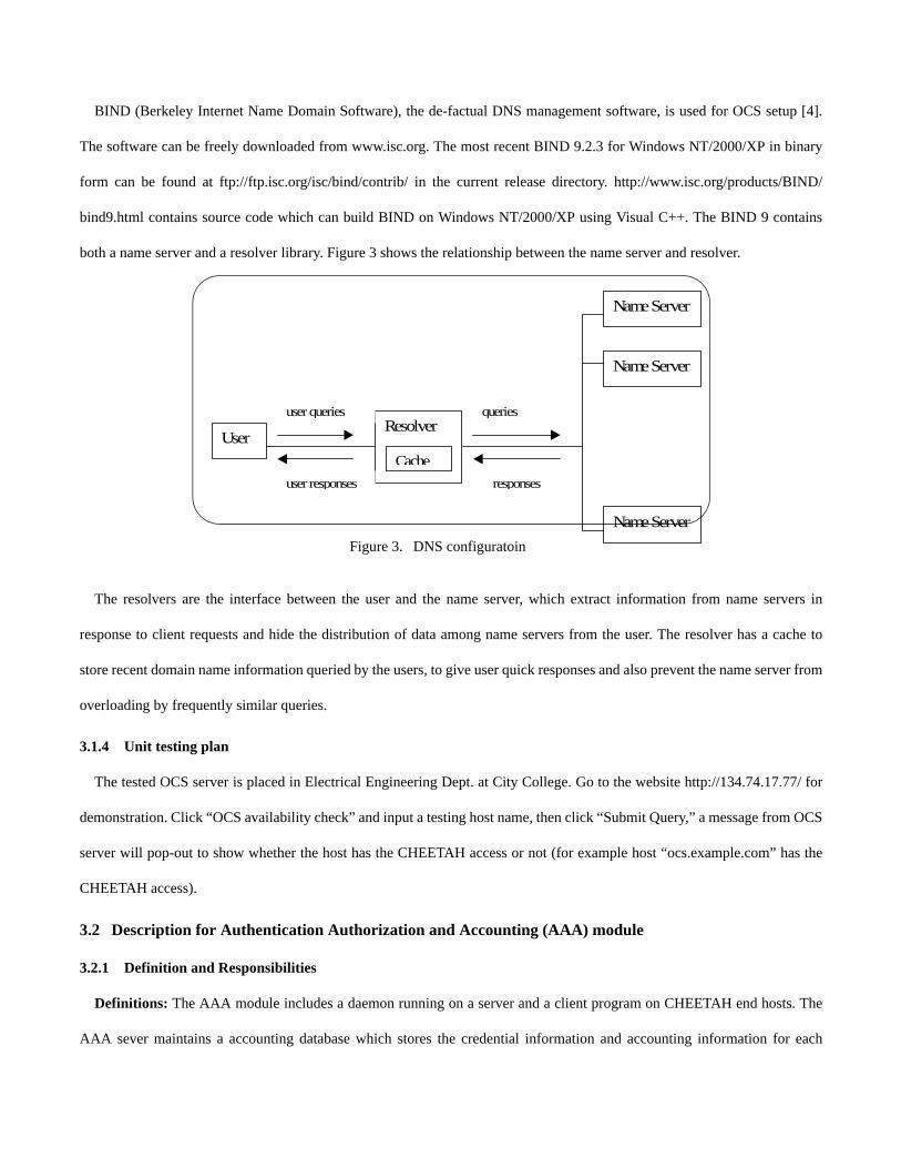
BIND (Berkeley Internet Name Domain Software), the de-factual DNS management software, is used for OCS setup [4].
The software can be freely downloaded from www.isc.org. The most recent BIND 9.2.3 for Windows NT/2000/XP in binary
form can be found at ftp://ftp.isc.org/isc/bind/contrib/ in the current release directory. http://www.isc.org/products/BIND/
bind9.html contains source code which can build BIND on Windows NT/2000/XP using Visual C++. The BIND 9 contains
both a name server and a resolver library. Figure 3 shows the relationship between the name server and resolver.
The resolvers are the interface between the user and the name server, which extract information from name servers in
response to client requests and hide the distribution of data among name servers from the user. The resolver has a cache to
store recent domain name information queried by the users, to give user quick responses and also prevent the name server from
overloading by frequently similar queries.
3.1.4 Unit testing plan
The tested OCS server is placed in Electrical Engineering Dept. at City College. Go to the website http://134.74.17.77/ for
demonstration. Click “OCS availability check” and input a testing host name, then click “Submit Query,” a message from OCS
server will pop-out to show whether the host has the CHEETAH access or not (for example host “ocs.example.com” has the
CHEETAH access).
3.2 Description for Authentication Authorization and Accounting (AAA) module
3.2.1 Definition and Responsibilities
Definitions: The AAA module includes a daemon running on a server and a client program on CHEETAH end hosts. The
AAA sever maintains a accounting database which stores the credential information and accounting information for each
User Resolver
Name Server
Name Server
Name Server
user queries
user responses
queries
responses
Cache
Figure 3. DNS configuratoin
CHEETAH service user.
Responsibilities: The AAA client program on the end hosts sends out AAA credential check requests to AAA servers after
an end host determines that the correspondent end host has CHEETAH connectivity through OCS query. The AAA server
receives request from user and responses with an authentication message. If an end host passes the AAA credential check and
the followed CHEETAH circuit setup is successful, the AAA server also records the CHEETAH circuit usage information for
accounting purpose, e.g. the duration and the bandwidth of a CHEETAH circuit.
3.2.2 Uses/Interactions
The following open source software is needed at CHEETAH end hosts to setup the AAA system: Postgresql [8], Libnet [6],
Linux-PAM [7], Freeradius [8].
Radclient, which is included in the Freeradius installation package, can be found under Linux directory “/usr/local/bin.” The
CHEETAH end host calls Radclient to communicate with Radius Authentication and Authorization server via port number
1812 and 1813.
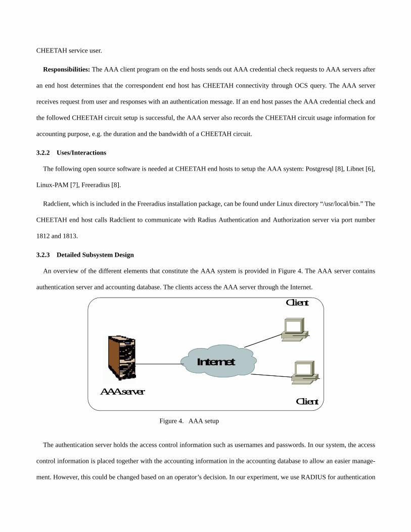
3.2.3 Detailed Subsystem Design
An overview of the different elements that constitute the AAA system is provided in Figure 4. The AAA server contains
authentication server and accounting database. The clients access the AAA server through the Internet.
The authentication server holds the access control information such as usernames and passwords. In our system, the access
control information is placed together with the accounting information in the accounting database to allow an easier manage-
ment. However, this could be changed based on an operator’s decision. In our experiment, we use RADIUS for authentication
Internet
AAA server
Client
Client
Internet
AAA server
Client
Client
Figure 4. AAA setup

servers.
The accounting database is a SQL database which holds the accounting information for the users and optionally it might
hold the access control information such as usernames and passwords. It is possible to configure the user credentials and
accounting information in the Postgres SQL DataBase from Internet.
About RADIUS: Several AAA protocols exist today; the most common is the Remote Access Dial In User Servizio
(RADIUS). Radius is a client-server system. The RADIUS document specifies a protocol used for Authentication and Autho-
rization and Accounting. This report extends the use of the RADIUS protocol to cover delivery of accounting information
from the client to a RADIUS AAA server. Key features of RADIUS Accounting include:
1. Client/Server Model.
2. Radius protocol uses a shared key to send the authentication and accounting messages. The shared key we used is
“c3pp0n4.” To change the key to go on root in clients.conf file.
3. The client is responsible for passing user accounting information to a designated RADIUS accounting server.
4. The RADIUS accounting server is responsible for receiving the accounting request and returning a response to the client
indicating that it has successfully received the request.
5. The RADIUS accounting server can act as a proxy client to other kinds of accounting servers.
Transactions between the client and RADIUS accounting server are authenticated through the use of a shared secret, which
is never sent over the network. All transactions are comprised of variable length Attribute-Length-Value 3-tuples. New
attribute values can be added without disturbing existing implementations of the protocol. More information about Radius can
be found on RFC 2866.
3.2.4 Unit testing plan
The tested AAA server is placed in Electrical Engineering Dept. at City College. Go to the website http://134.74.17.77/ for
demonstration.
The authentication page is shown in Figure 5. After input the username and password (The test username and password are

both “song”) and click “submit Query”, the result will be shown in Figure 6.
To view the accounting information in the Accounting server, go to http://134.74.17.77/pg/. The username and the password
are both “radius”. After the login in, click "radius", then "Tables". On the "radacct" row, if you clicks "browse", you will see all
Figure 5. Authentication page
Figure 6. Login result page

the accounting information (shown in Figure 7).
3.3 Description for optional Router Disconnect module
3.3.1 Definition and Responsibilities
Definitions: Router Disconnect module is a executable software that talks to Cisco router to automate the router configura-
tion according to a script. Need to consider MSPP side.
Responsibilities: In default model, the router is configured to have several component links bundled together to form a bun-
dled link for TCP/IP traffic. In CHEETAH mode, the router is configured to unbundled one or more component links so that
these links can be used for CHEETAH traffic.
3.3.2 Constraints
“Expect,” an open source tool, need to be installed in the client side or application software for router disconnect. It can be
downloaded from http://expect.nist.gov/.
Link bundling is used to realize router disconnect. Link bundling is only supported by Cisco 12000 series routers and line
cards [9]. For a Gigabit EtherChannel or POS Channel to operate correctly with equal cost load balancing, the Link Bundling
feature requires that all line cards in a Cisco 12000 Series Internet Router support the ingress decision capability. Only the fol-
lowing Cisco 12000 series line cards support ingress decision capability:
Figure 7. Accounting information page
• Engine 0 Asynchronous Transfer Mode (ATM) line cards
• Engine 0 Channelized DS3/E3 line cards
• Engine 0 Dynamic Packet Transport (DPT) line cards
• Engine 0 Packet-over-SONET line cards
• Engine 1 Fast Ethernet line cards
• Engine 1 Gigabit Ethernet line cards
• Engine 2 8-port OC-3/STM-1 ATM line cards
• Engine 2 Dynamic Packet Transport (DPT) line cards
• Engine 2 Gigabit Ethernet line cards
• Engine 2 Packet-over-SONET line cards
• IP Service Engine (ISE) line cards:
• ®C 4-Port Gigabit Ethernet ISE line card
• ®C 8-Port OC-3c/STM-1c POS/SDH ISE line card
• ®C 16-Port OC-3c/STM-1c POS/SDH ISE line card
• ®C 4-Port OC-12c/STM-4c POS/SDH ISE line card
• ®C 1-Port OC-48c/STM-16c POS/SDH ISE line card
• Engine 4+ line cards
The following Cisco 12000 series line cards do not support ingress decision capability:
• Engine 0 Channelized DS1/E1, OC-3, and T3 line cards
• Engine 2 Asynchronous Transfer Mode (ATM) line cards, except for the 8-port OC-3/STM-1 ATM line card
• Engine 4 line cards
3.3.3 Uses/Interactions
Expect is a tool for automating interactive applications such as telnet, ftp, passwd, fsck, rlogin, tip, etc. It talks to other inter-
active programs according to a script. Most of the Linux installations already contain a version of Expect. The scripts for link
bundle (bundle.exp) and unbundled (unbundle.exp) are listed in Appendix 8.1 for reference.
3.3.4 Detailed Subsystem Design
In Cheetah network, the hosts are connected by leased high-speed link. It would be a waste to let this high-speed circuit lie
unused when there is no Cheetah communication. Hence we propose a scheme in which such leased circuits could be used to
interconnect enterprise IP routers with IP routers on Internet2, ESnet or Internet itself, until a Cheetah request appears. When
it does, this router-to-router circuit is torn down and the Cheetah Ethernet/EoS circuit is established for the duration of the ses-
sion. In the mean time, the client needs to be authenticated before it starts to use Cheetah service and how long the client uti-
lizes this service needs to be recorded for billing purpose.
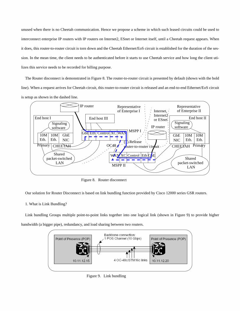
The Router disconnect is demonstrated in Figure 8. The router-to-router circuit is presented by default (shown with the bold
line). When a request arrives for Cheetah circuit, this router-to-router circuit is released and an end-to-end Ethernet/EoS circuit
is setup as shown in the dashed line.
Our solution for Router Disconnect is based on link bundling function provided by Cisco 12000 series GSR routers.
1. What is Link Bundling?
Link bundling Groups multiple point-to-point links together into one logical link (shown in Figure 9) to provide higher
bandwidth (a bigger pipe), redundancy, and load sharing between two routers.
Figure 8. Router disconnect
GbENIC
10MEth.
End host I
Primary CHEETAH
GbENIC
10MEth.
10MEth.
End host II
PrimaryCHEETAH
Shared packet-switched
LAN
Shared packet-switched
LAN
MSPP I
MSPP II
Eth ControlGbE XC WAN10MEth.
EthControl GbEXCWAN
Signalingsoftware
Signalingsoftware
OC48
End host III
(1) Releaserouter-to-router circuit
IP router
IP router
Representativeof Enterprise I
Representativeof Enterprise IIInternet,
Internet2or ESnet
Figure 9. Link bundling

The following types of link bundling are supported on Cisco 12000 Series Internet Routers:
• Gigabit EtherChannel is used to bundle multiple Gigabit Ethernet (GE) interfaces.
• POS Channel is used to bundle multiple Packet-over-SONET (POS) interfaces.
Use link bundling on Cisco 12000 Series Internet Routers in networks under the following conditions:
• Faster links do not exist.
• The next step available for increasing link capacity is too expensive.
• The operational costs to increase link capacity are too high.
Gigabit Ethernet and POS Channel link bundling on Cisco 12000 Series Internet Routers provide flexible and incremental
bandwidth with link redundancy and higher layer transparency to network applications. You can use Gigabit EtherChannel and
POS channel in multiple locations in the same network.
Gigabit EtherChannel and POS Channel allow you to increase and decrease bandwidth by simply adding or removing an
interface from the link bundle. Also, by incrementally increasing bandwidth, you are no longer dependent on the fixed
increases in bandwidth (for example, 1 Gbps, 10 Gbps, and so on) determined by the physical layer technology.
The failure of a single link does not necessarily cause a network failure. Traffic is redirected to remaining links within the
channel without user intervention. As a result, the availability of a GE or POS link is increased.
On Cisco 12000 Series Internet Routers, link bundling is implemented so that a virtual interface (a POS Channel or Gigabit
EtherChannel) is created for each link bundle. You can dynamically add and delete links to the virtual interface. The virtual
interface is treated as a single interface on which you configure an IP address and other software features used by the link bun-
dle, instead of configuring them on individual GE and POS interfaces.
Packets sent to the link bundle are forwarded on one of the links in the bundle. Load balancing is supported on all links in a
bundle using per-destination load balancing based on a hash calculated using the source and destination IP addresses in the IP
packet. Per-destination load balancing ensures that packets are delivered in order.
2. How Link bundling works?
• A Gigabit EtherChannel or POS Channel link bundle is created on a line card or across multiple line cards.

• An adjacency representing the new bundle is created in the forwarding information base (FIB) table on the gigabit route
processor (GRP) and is forwarded to all the line cards. This adjacency represents a virtual link and has pointers to indi-
vidual links in the bundle.
• As incoming data packets are received by the router, line cards route packets to the link bundle as a whole. The ingress
line card recognizes the virtual adjacency, and properly routes and load balances the packets across the sub-adjacencies
represented by the virtual adjacency. Packets are properly routed and load balanced towards the bundle, and then prop-
erly transmitted across the bundle.
3. How Link Bundling Helps in Our Project
Link bundling can be applied during the mode transfer between Cheetah mode and default mode to minimize the TCP
packet loss. In default mode, all the component links are bundled together for TCP traffic. When a Cheetah circuit requires, the
router can un-bundle one or several component links, so that these links can be used for Cheetah circuit. The remained links in
the bundled link are used for TCP traffic.
3.3.5 Unit testing plan
The scripts for link bundle (bundle.exp) and unbundled (unbundle.exp) are located at computer mvstu5.cs.virginia.edu
under directory /home/cuny/). Here is an example of link bundling execution:
[cuny@mvstu5 cuny]$ expect bundle.exp 128.143.67.146 1 192.168.18.1 255.255.255.0 pos3/0 pos3/2
This command bundles POS channel 3/0 and 3/2 of router 128.143.67.146 together and assigns °×Group 1°± to the bundled
link, and an IP address 192.168.18.1 to this virtual interface.
Examples of link unbundling execution:
[cuny@mvstu5 cuny]$ expect unbundle.exp 128.143.67.146 1 pos3/2
This command removes POS channel 3/2 from link-bundling group 1 of the router 128.143.67.146.
[cuny@mvstu5 cuny]$ expect unbundle.exp 128.143.67.146 1
This command totally un-bundles the pre-bundled link and removes the bundled group 1.
3.4 Description for Routing Decision (RD) Module
3.4.1 Definition and Responsibilities
Definitions: This module make a routing decision for the end-host applications, which have CHEETAH connectivity. Run-
ning as a daemon process, this module measures the Internet status periodically, maintains a network-parameter database, lis-
tens on applications’ queries, uses the routing decision algorithm presented in [2] to calculate and compare quantitatively the
costs of setting up a CHEETAH circuit and using the primary Internet path, and then provide the application a recommenda-
tion on whether to set up a circuit or not.
Responsibilities: When an application wants to transfer a file, it will consult this module to see whether it should set up a
CHEETAH circuit or just use the primary Internet path. Hence this module’s main responsibility is to give a recommendation
on choosing the path. To do this on a quantitative basis, it has to measure the Internet status and then use the measurement
results to calculate the cost of using the primary Internet path and that of opening a circuit. But the measurement of Internet
status may take a certain amount of time (for example pathload [10] takes 5-6 seconds to finish one measurement from UVa to
NCSU), which adds overhead to the circuit transfer in the case that the CHEETAH circuit is preferred. To shorten this over-
head we’d better let this Routing Decision module maintain an Internet status database and use the data inside this database as
much as possible.
3.4.2 Constraints
First of all, the assumption we make here is the status of the Internet does not change in a very short period, say the period
of the measurement carried out by this module, and the status of the past short period indicates the trend in the next period in
most of the time. Second, The data base will require some memory space. Third in the first phrase of implementation we only
realize consideration the aspect of delay analysis, however leave out the utilization aspect.
3.4.3 Uses/Interactions
Applications communicate with this module through Socket or IPC api. Our first step is using Socket, which means this
module’ daemon keeps listening on a well-known port to wait for applications’ connections. After an application connect to
the listening port, it send a query that includes the destination IP address, file size and bandwidth expected. Then the daemon
will do the calculations and reply with a recommendation. Other parameters may be needed in the query, if we involve the
authentication or priority issues, which should be added to this software in future.
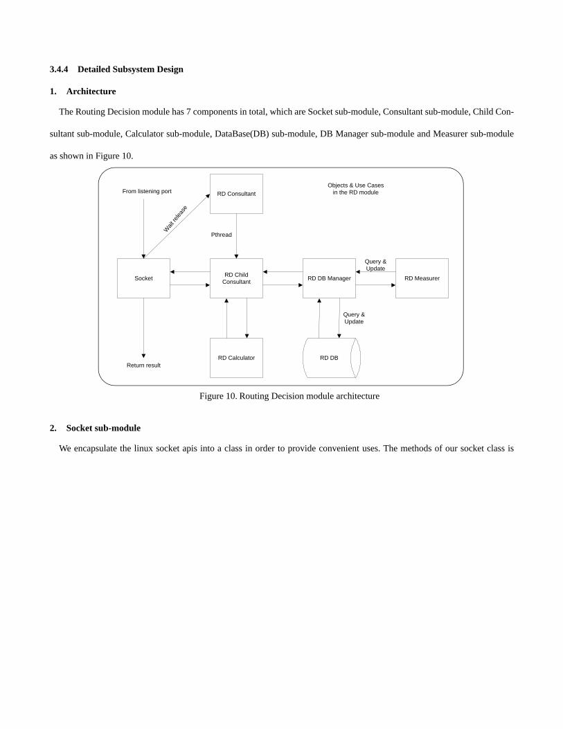
3.4.4 Detailed Subsystem Design
1. Architecture
The Routing Decision module has 7 components in total, which are Socket sub-module, Consultant sub-module, Child Con-
sultant sub-module, Calculator sub-module, DataBase(DB) sub-module, DB Manager sub-module and Measurer sub-module
as shown in Figure 10.
2. Socket sub-module
We encapsulate the linux socket apis into a class in order to provide convenient uses. The methods of our socket class is
RD Consultant
RD Calculator
Socket RD DB Manager
RD DB
RD MeasurerRD ChildConsultant
Objects & Use Casesin the RD moduleFrom listening port
Wait
relea
se
Pthread
Return result
Query &Update
Query &Update
Figure 10. Routing Decision module architecture

illustrated in Figure 11 below.
3. Consultant and Child Consultant sub-module
The consultant sub-mod listens on the well-known port and accept applications’ connections. Then it create a child consult-
ant thread to handle a particular query. The operation flow of Consultant and Child Consultant sub-mod is shown below.
4. Calculator sub-module
The Calculator sub-mod perform the job of computing the costs of setting up a circuit and using the primary Internet path.
My Socket
myBind
myListen
myConnect
myAccept
mySend
myRecv
MySocket(construct)
MySocket(construct)
Server side Client sideBoth sides
Figure 11. Socket sub-module
RD Consultant
Bind Socket & Listen
Accept a connection
Weekday?
Create a thread
Call back function
Get query params
Call DB Manager
Compare and return
Run Handle queryCall back
Y
NExit
RD DB Manager
Exit
Figure 12. Consultant and Child Consultant sub-module

5. DB sub-module
DB sub-mod stores the Internet status parameters and responsible to update and query routines. The organization of DB sub-
mod is presented in the figure beneath.
6. DB Manager sub-module
DataBase Manager sub-mod is in charge of handling the retrieval queries from the Child Consultant sub-mod and its work
flow is like below.
TABLE I ENTRY IN THE DB
IP address TTL RTT
(circuit) Rs K Tsp rho-sig rho-sp p Wmax(client side)
T0 b RTT (tcp)
RD DB
DBQuery DB
Hit?
Y
Return the result
NCall Measure
Update DB
Measurer
Figure 13. DB sub-module

7. Measurer sub-module
Measurer sub-mod is composed by several Internet measurement tools’ code and works in Client/Server style, which means
the client side RD application will talk to its peer on the destination machine and start the measurement. The idea is shown
below.
3.5 Description for Signaling Module
3.5.1 Definition and Responsibilities
Definitions: The signaling module is used to create circuits across the LAN and the backbone network. The signaling tech-
RD DB Manager
Query DB
Hit?
Y
NCall DB update RD DB
Return the results
RD DB
Exit
Figure 14. DB Manager sub-module
RD Measurer
Client side Server side
PathloadPathrate
PathloadPathrate
Figure 15. Measurer sub-module
nologies include RSVP-TE SONET extension, VLAN and TL1 cross connection.
Signaling module exists both on the VLSR [11] and the end hosts. However the signaling modules on VLSR and end hosts
consist of different sub modules. Generally we can divide the signaling module into three parts: RSVP daemon, RSVP API
and SNMP (for Ethernet switch) / TL1 (for MSPP) module. The module on end hosts consists of RSVP daemon and RSVP
API. The module on VLSR consists of RSVP-TE daemon and SNMP/TL1 module. The SNMP/TL1 module is integrated with
RSVP-TE daemon and invisible to other modules of the system.
Responsibilities: The responsibilities of signaling module is to create, release and maintain the circuit between two end
hosts. Here the circuit include the SONET circuit in backbone, the setup of VLAN in LAN and the cross connections on
MSPPs.
3.5.2 Constraints
Currently the routing function is not implemented in the VLSR RSVP-TE code. So the initiator of the RSVP-TE signaling
must explicitly give the route of the signaling. The information of the MSPP, including the IP address, port number of the
Ethernet Card and Optical Card, should also be given by the end host.
3.5.3 Uses/Interactions
The RSVP-TE daemons on VLSRs don’t collaborate with any other modules. The daemons on different machines commu-
nicate with each other through RAW IP message. As indicated in the definition part, the SNMP/TL1 module is invisible to
other modules.
The RSVP-TE daemons on end host talks to user application through RSVP_API class. User application can include the
header files of RSVP_API in the source code and link the RSVP-TE library with their application.
For end hosts which act as RSVP-TE receivers, the application need to know the IP addresses and port numbers of both
sender and receiver before they create the RSVP-TE session to wait for PATH message from sender. To be specific, the
receiver application should create an instance of RSVP_API class and define a set of upcall functions which will be triggered
when certain messages, such as PATH, RSV_CONFIRM, etc., are received. It should also use RSVP_API:: createSession to
create a session to register the upcall functions and wait for the PATH message from sender.
For end hosts acting as RSVP-TE senders, besides all the operations that the receivers need to do, the application of senders
also need to do following things:

• Provide the routing information (Might not be necessary when OSPF-TE is implemented later)
• Provide IP, port information of the MPSS/Ethernet Switch on the route
• Provide circuit request information to generate sender TSpec object.
• Create Label
• Call createSender with the information above to send out PATH message
3.5.4 Detailed Subsystem Design
TBD
3.6 Description for Transport Protocol Module
3.6.1 Definition and Responsibilities (REQUIREMENTS)
The transport protocol module should:
• provide reliable data transfer. It should guarantee ordered, error-free, and no-duplicates delivery.
• provide high goodput for file transfers.
• provide high utilization of the reserved circuit. The reserved network resources should be used as efficiently as possible
and should be held for only as long as they are required.
• be efficient in a multitasking environment, i.e. the transport protocol implementation should not be CPU intensive.
• have an application-level implementation, that is easy to deploy widely, and not require any kernel-level changes.
• provide an Application Programming Interface (API) which can be used by an application.
3.6.2 Constraints
TBD
3.6.3 Uses/Interactions (INTERNAL FUNCTIONS/ EXTERNAL INTERFACE)
Given below are the design decisions taken to meet the requirements listed in subsection 3.6.1.
• Application-level implementation (Req. 5): The transport protocol implementation should utilize the kernel network
stack through the socket API that provides an interface to the TCP/ UDP layer.
• High goodput, high circuit utilization (Req. 2, 3): TCP’s congestion and flow control algorithms, designed for sharing
network resources fairly, adversely affect utilization of reserved resources. Use UDP to transport the data packets-
since UDP has no flow or congestion control- and add these functionalities (if required) on top of the UDP layer. For
high circuit utilization, use a steady sending rate (equal to the reserved circuit rate) which is maintained using a fixed
inter-packet transmission time. High goodput requires a high sending rate as well as a low error/loss rate; these being
conflicting requirements because of the end-host limitations. Take end-host capabilities into consideration when choos-
ing the sending rate (this should be done while setting up the circuit).
• Reliability (Req. 1): The reserved circuit ensures in-sequence delivery of data packets (and hence, no duplicates). Take
advantage of this by adding a sequence number to the data packets to detect loss at the receiver, instead of maintaining
timers at the sender. Since we use UDP to transmit the data packets, the UDP checksum can be used to detect errors.
The receiver should report errors/ loss to the sender. Use a reliable TCP channel for these reverse direction control
packets.
• CPU utilization and API (Req. 4, 6): These are implementation issues and should be kept in mind while writing the
code.
Internal Functions:
Sender
• Send data at the fixed circuit rate. To do this, calculate the inter-packet time for the required circuit rate, assuming pack-
ets are the maximum allowed size (MTU). Every inter-packet time send 1 packet using the UDP socket. Add sequence
numbers to the payload (since UDP does not add sequence numbers), for error detection at the receiver.
• Retransmit packets that were lost or had errors. Wait for acknowledgement (ACK) from the receiver, keeping
unACKed data in memory. Error indications from the receiver inform the sender of which packets need to be retrans-
mitted and those portions of the data are marked for retransmission.
Receiver
• Receive data and identify lost/ incorrect packets.
• ACK correctly received packets and inform the sender of missing/ incorrect packets.
• Use the data packets’ sequence numbers to reassemble the received data in memory.
External Interface
The transport protocol module interfaces with the application (e.g. SFTP or Web Application). The application uses the

transport protocol API to send/ receive data.
Sender
The application has to supply the circuit rate, so that the transport protocol module can calculate the inter-packet time. The
application should also provide information about the data to be sent- the start memory address and length of the block to be
sent, where a block is a subset of the file to be transferred (it is unlikely that the whole file can be stored in memory). The
application can either reuse these blocks of memory (the file will usually be larger in size than 1 block, requiring multiple
blocks to be transmitted) or assign new memory blocks. In case memory is reused, the transport protocol module should indi-
cate to the application when a block of data has been sent correctly (HOW TO DO THIS?). If memory is not reused, the trans-
port protocol module should deallocate the block of memory once it has been sent out correctly.
Receiver
The receiver should reassemble the received data in memory. The application should request data (PERIODICALLY?) and
the transport protocol receiver should provide the start address and length of a correctly received block of data.
3.6.4 Detailed Subsystem Design
TBD
3.7 SFTP
TBD
3.8 Web Application
3.8.1 Definition and Responsibilities
Definitions: The Web Application is one of the use cases for CHEETAH. It is oriented to commercial users such that they
can enjoy the CHEETAH service on the World Wide Web without knowing the underlying mechanism of CHEETAH. When
the users click a URL on the web, the Web Application is triggered to automatically utilize CHEETAH to improve large file
transfer delays.
Responsibilities: The Web Application is aimed to utilize CHEETAH to improve bulk data transfer delays via Web. It con-
sists of a CGI (Common Gateway Interface) script, a web server side application and a client side application. When a URL is
requested by a web client, the CGI is invoked to run at the web server. The CGI interacts with a web server (e.g. APACHE)
and calls the server side application to return the file to the client. The server side application collaborates with other CHEE-

TAH modules (OCS/AAA, routing decision, router disconnect, RSVP-TE signaling, and FRTP) while the client side applica-
tion is designed to run on the client side as a daemon in the background to establish a frtp connection with the server side
application. The Web Application is transparent to the users. Specifically, the users don’t need to know if CHEETAH is avail-
able for them or decide if it is appropriate to use CHEETAH. Instead, the application will provide them proper services.
3.8.2 Constraints
The current version of the Web Application is run on Linux Redhat 9.0 with APACHE 2.0 as the web server. Since the Web
Application invokes the other CHEETAH modules, all the constraints that those modules have presented should be met. Fur-
thermore, we assume that our web site is not very large and scalable. This assumption is critical because the server launches a
subprocess to run the CGI program for each click on the URL and thus gets a very heavy load when there are many requests at
the same time. In light of this assumption, although there are speed and performance issues with CGI, it is reasonable for us to
use it because we do not expect many simultaneous hits on the web site, for example, over 1000.
3.8.3 Uses/Interactions
The Web Application collaborates with the following CHEETAH modules: OCS, AAA, routing decision, router disconnect,
signaling and FRTP. The specific interaction lists as follow:
1. OCS
The OCS is based on BIND9 (open source for DNS setup). The DNS administrator needs to install BIND9 and adds a string
like “OCS available” to the TXT type Resource Record (RR) in the DNS server database. Then, the Web Application calls pro-
gram nslookup to examine if the remote host can be reached by CHEETAH. The parameters of nslookup are set as follows:
> nslookup -type=TXT hostname
If the returned value of nslook has the string “OCS available” in its RR, that means the remote host can be reached by
CHEETAH circuit.
2. AAA
The open source software freeradius-0.9.3 should be installed in the CHEETAH host. Then, the Web Application calls rad-
client through port 1812 and 1813 to communicate with Radius Authentication and Authorization server.
• For authentication, call the following shell script:
> /usr/local/bin/radclient -d /usr/local/etc/raddb -x XX.XX.XX.XX (radius server IP address) auth c3pp0n4 (the shared

secret key stored in the server side) << EOF
> User-Name = XXXX
> password = XXXX
> EOF
If the authentication is successful, the client will receive a message saying “Access-Accept packet from host
XX.XX.XX.XX:1812, id =X, length=XX”.
• For accounting, call the following shell script to record CHEETAH circuit setup time:
> /usr/local/bin/radclient -d /usr/local/etc/raddb -x XX.XX.XX.XX (radius server IP address) acct c3pp0n4 (the shared
secret key stored in the server side) << EOF
> User-Name = XXXX
> NAS-IP-Address = 10.0.0.1 (not used)
> NAS-Port = 1813 (not used)
> Framed-IP-Address = XX.XX.XX.XX (the client’s IP address)
> Acct-Session-Id = 1
> NAS-Port-Type = 15
> EOF
Call the following shell script to record CHEETAH circuit teardown time:
> /usr/local/bin/radclient -d /usr/local/etc/raddb -x XX.XX.XX.XX (radius server IP address) acct c3pp0n4 (the shared
secret key stored in the server side) << EOF
> User-Name = XXXX
> NAS-IP-Address = 10.0.0.1
> NAS-Port = 1813
> Framed-IP-Address = XX.XX.XX.XX (the client’s IP address)
> Acct-Status-Type = Stop

> #Acct-Input-Octets = $3
> #Acct-Output-Octets = $4
> Acct-Session-Id =1
> #Acct-Session-Time = 100
> Acct-Terminate-Cause = 1
> NAS-Port-Type = 15
> EOF
3. Routing decision
Parameters: client IP address, file size and bandwidth requirement.
Return value: true or false to indicate if the request for a CHEETACH circuit is met or not.
4. Routing disconnect
The open source software Expect should be installed. The scripts for link bundle (bundle.exp) and unbundled (unbun-
dle.exp) have been designed by the router disconnect module.
• For link bundling, the Web Application invokes the expect command, for example:
> expect bundle.exp 128.143.67.146 1 128.143.67.254 255.255.0.0 pos3/1 pos3/2 pos3/3
The above command bundles POS channel 3/1, 3/2 and 3/3 of router 128.143.67.146 together, assigns “Group 1” to the bun-
dled link, and an IP address 128.143.67.254 to this virtual interface
• For link unbundling, the Web Application invokes the expect command, for example:
> expect unbundle.exp 128.143.67.146 1 pos3/1 pos3/2 The above command removes POS channel 3/1 and 3/2 from link-bundling group 1 of the router 128.143.67.146.
Another example is
> expect unbundle.exp 128.143.67.146 1
The above command totally unbundles the pre-bundled link and removes the bundled group 1.
5. RSVP-TE Signaling

RSVP API: createSender, receiveAndProcess
6. FRTP
FRTP API: CSabulSender, CSabulRecver
3.8.4 Detailed Subsystem Design
Provide a detailed description of this software component (or a reference to such a description). Details of module structure,
main functions, data structure and flowcharts.
The Web Application is made up of a CGI (Common Gateway Interface) script and a client side application. The workflow
of the CGI program is depicted in Figure 16.
Receive a URL request from a web client
The client can be reached byCHEETAH circuit(OCS/AAA)
Request a CHEETAH circuit(Routing Decision)
Set up a circuit(Signaling)
Send the file via FRTP
Release the circuit
Yes
Yes
Succeed
Send the file via TCP
No
No
Fail
Router Disconnect
Get client IP address, file size andbandwidth
Figure 16. The workflow of the Web application CGI program
4. Testing Issues
TBD
system integration and system tests
4.1 Classes of tests
The types of tests to be conducted are specified, including as much detail as is possible at this stage. Emphasis here is on
black-box and white-box testing.
4.2 Expected software response
The expected results from testing are specified.
5. Schedule
TBD
6. Glossary
TBD
7. Bibliography
[1] “NSF Experimental Infrastructure Networks (EIN) Project”, cheetah.cs.virginia.edu[2] M. Veeraraghavan, X. Zheng, H. Lee, M. Gardner, W. Feng, CHEETAH: Circuit-switched High-speed End-to-End
Transport ArcHitecture, Proc. of Opticomm 2003, Oct. 13-17, 2003. Dallas, TX. [3] W. Feng and P. Tinnakornsrisuphapá, “The Failure of TCP in High-Performance Computational Grids,” Proceeding of
SC2000: High-Performance Network and Computing Conference, Dallas, TX, November 2000.[4] “ISC BIND,” http://www.isc.org/index.pl?/sw/bind/.[5] “Postgresql,” http://www.postgresql.org/.[6] “Libnet,” http://libnet.sourceforge.net/.[7] “Linux-PAM”, http://www.kernel.org/pub/linux/libs/pam/.[8] “Freeradius,” http://www.freeradius.org/.[9] Cisco, “Link Bundling on Cisco 12000 Series Internet Routers,” http://www.cisco.com/en/US/products/sw/iosswrel/
ps1829/products_feature_guide09186a0080103708.html.[10] “Pathrate,” http://www.cc.gatech.edu/fac/Constantinos.Dovrolis/pathrate.html.[11] J. Sobieski, T. Lehman, B. Jabbari, “DRAGON Dynamic Resource Allocation via GMPLS Optical Networks,” presen-
tation at the NSF Shared Cyberinfrastructure (SCI) Division Principal Investigators Meeting, Feb. 18-20, 2004.
8. Appendix
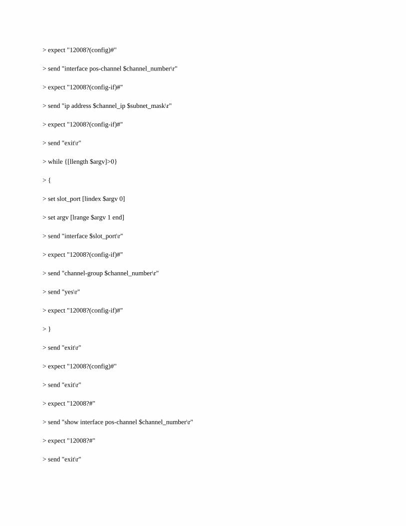
8.1 Cisco 12000 series GSR router link bundling script
> bundle.exp

> set timeout -1
> if {$argc<5}
> {
> send_user "usage: expect bundle.exp Router_IP Channel_number Channel_IP Subnet_Mask Slot/Port\r\n"
> exit
> }
> set router_ip [lindex $argv 0]
> set argv [lrange $argv 1 end]
> set channel_number [lindex $argv 0]
> set argv [lrange $argv 1 end]
> set channel_ip [lindex $argv 0]
> set argv [lrange $argv 1 end]
> set subnet_mask [lindex $argv 0]
> set argv [lrange $argv 1 end]
> spawn telnet $router_ip
> expect "Password:"
> send "EIN\r"
> expect "12008?>"
> send "enable\r"
> expect "Password:"
> send "EIN\r"
> expect "12008?#"
> send "configure terminal\r"
> expect "12008?(config)#"
> send "interface pos-channel $channel_number\r"
> expect "12008?(config-if)#"
> send "ip address $channel_ip $subnet_mask\r"
> expect "12008?(config-if)#"
> send "exit\r"
> while {[llength $argv]>0}
> {
> set slot_port [lindex $argv 0]
> set argv [lrange $argv 1 end]
> send "interface $slot_port\r"
> expect "12008?(config-if)#"
> send "channel-group $channel_number\r"
> send "yes\r"
> expect "12008?(config-if)#"
> }
> send "exit\r"
> expect "12008?(config)#"
> send "exit\r"
> expect "12008?#"
> send "show interface pos-channel $channel_number\r"
> expect "12008?#"
> send "exit\r"

> unbundle.exp
> set timeout -1
> if {$argc<2}
> {
> send_user "usage: expect unbundle.exp Router_IP Channel_number Slot/Port\r\n"
> exit
> }
> set router_ip [lindex $argv 0]
> set argv [lrange $argv 1 end]
> set channel_number [lindex $argv 0]
> set argv [lrange $argv 1 end]
> spawn telnet $router_ip
> expect "Password:"
> send "EIN\r"
> expect "12008?>"
> send "enable\r"
> expect "Password:"
> send "EIN\r"
> expect "12008?#"
> send "configure terminal\r"
> expect "12008?(config)#"
> if {![llength $argv]}
> {

> send "no interface pos-channel $channel_number\r"
> } else
> {
> while {[llength $argv]>0}
> {
> send "interface pos-channel $channel_number\r"
> expect "12008?(config-if)#"
> set slot_port [lindex $argv 0]
> set argv [lrange $argv 1 end]
> send "interface $slot_port\r"
> expect "12008?(config-if)#"
> send "no channel-group $channel_number\r"
> expect "12008?(config-if)#"
> }
> send "exit\r"
> }
> expect "12008?(config)#"
> send "exit\r"
> expect "12008?#"
> send "show interface pos-channel $channel_number\r"
> expect "12008?#"
> send "exit\r"