Embed Size (px)
Citation preview

8/3/2019 Chemical Earthing 2011 FAQ
http://slidepdf.com/reader/full/chemical-earthing-2011-faq 1/99
YourQuestions Answered!
Gobind AjwaniMarketing manager
[email protected] Systems & Solutions Pvt. Ltd.14/3, Bolton Compound,Mathura Road,Faridabad-121003( Haryana ) India
Tel: +91-129-4158603+91-9871330966
http://www.alfredkim.net
+91 8800797774, 9810531603,[email protected]

8/3/2019 Chemical Earthing 2011 FAQ
http://slidepdf.com/reader/full/chemical-earthing-2011-faq 2/99
6 Promises should be taken for choosingElectrical Engineering Profession :
I hate rest.
I have already enjoyed my life in childhood.
I love tension.I don't like to spend time with my family and
friends.
I love to work on sundays & holidays .I want to take revenge on myself.

8/3/2019 Chemical Earthing 2011 FAQ
http://slidepdf.com/reader/full/chemical-earthing-2011-faq 3/99
BIOGRAPHY OF ELECTRICITYI am Electricity. My home is in wires and conductors. My Father is Volta.My mother is Magnet and I ma a very important source of energy in modern times. I
have a son called “Electron” If you want to know about me you can consult mysubordinate “Voltmeter” I have a brother called Voltage.
I am very useful. Without me your life is very difficult. I am mostly used in Industries Agriculture etc. Without me no “ SUPER COMPUTER” can
work. I would like to summarize myself as follows :-
I am an electric current
And not very tolerant
I am extremely useful, If you are careful
The moment you become careless
I also become senseless And I become the cause of tragedy
Whether it is “a Man” or “a Lady”

8/3/2019 Chemical Earthing 2011 FAQ
http://slidepdf.com/reader/full/chemical-earthing-2011-faq 4/99
Your Questions – Our Answers Why Electrical Earthing?
Why G.I. is Better than Copper?
How Earthing System Works?
What is System of grid earthing?
Why earthing near to equipment?
Why Discard Pit Type Earthing? Why Switch to Chemical Electrode Earthing?
Why control floating neutral voltage?
What are Stray Voltages?
Why Water new earth bore?
How is price comparable Cu vs. Chemical earthing?
How to select & Install Alfredkim Earthing Systems?
Why Chemical Earthing is more Durable and reliable?
How To Audit Existing Earthing System and Provide Solutions
Want a Electrician in India
Do’s and Don’ts – General Precautions
Specification For Alfredkim Electrodes

8/3/2019 Chemical Earthing 2011 FAQ
http://slidepdf.com/reader/full/chemical-earthing-2011-faq 5/99
SPECIFICATION FOR ALFREDKIMCHEMICAL EARTHING
A. MODEL- AKE0250 (50mm x 2000mm)
10) GBFC(Ground Back Fill Compound) :-
I) Minimum 30kg It is soil enrichment chemical mainly consisting of
Aluminum Silicate.
II) It absorbs moisture but doesn’t get dissolved in water.
III) It can absorb water 13 times of its weight.
IV) The top & bottom of the pipe is sealed permanently.
11) Earth fault capacity:-
100KVA
12) Surface Area:-
314000mm
13) Brand:- Alfredkim
14) Manufactures:-
ALFREDKIM SYSTEMS & SOLUTIONS PRIVATE
LIMITED
14/3, Bolton Compound, Mathura Road, Faridabad-121003, Haryana (India)
www.alfredkim.net

8/3/2019 Chemical Earthing 2011 FAQ
http://slidepdf.com/reader/full/chemical-earthing-2011-faq 6/99
SPECIFICATION FOR ALFREDKIMCHEMICAL EARTHING
A. MODEL- AKE0250 (50mm x 2000mm)1) Type of Earthing:-
Sealed maintenance free chemical filled earthing electrode.
2) Diameter of the pipe:-
50mm
3) Thickness of the pipe:-
1.5mm (16 S.W.G.)
4) Length of the pipe:-
2000mm
5) Galvanized Thickness:-
80-100micron
6) Type of galvanizing:-
Hot dipped
7) Size of the conductor:-
30x6 G.I. strip
8) Terminal diameter:-
12mm
8/3/2019 Chemical Earthing 2011 FAQ
http://slidepdf.com/reader/full/chemical-earthing-2011-faq 7/99
SPECIFICATION FOR ALFREDKIM CHEMICAL EARTHING
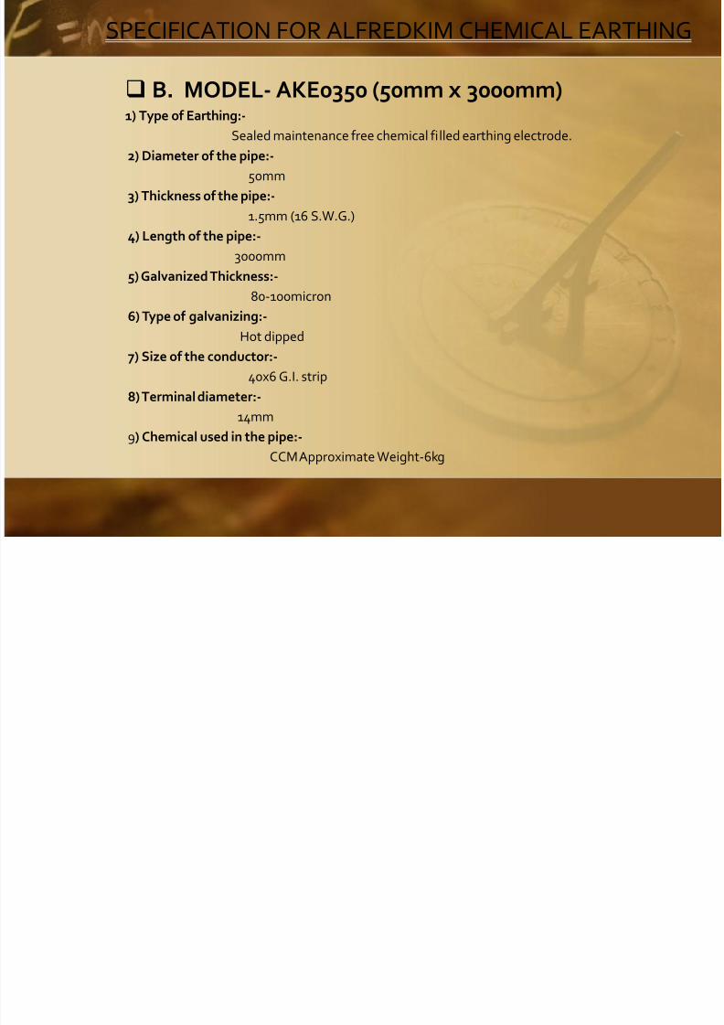
B. MODEL- AKE0350 (50mm x 3000mm) 1) Type of Earthing:-
Sealed maintenance free chemical filled earthing electrode.
2) Diameter of the pipe:-
50mm
3) Thickness of the pipe:-
1.5mm (16 S.W.G.)
4) Length of the pipe:-
3000mm
5) Galvanized Thickness:-
80-100micron
6) Type of galvanizing:-
Hot dipped
7) Size of the conductor:-
40x6 G.I. strip8) Terminal diameter:-
14mm
9) Chemical used in the pipe:-
CCM Approximate Weight-6kg

8/3/2019 Chemical Earthing 2011 FAQ
http://slidepdf.com/reader/full/chemical-earthing-2011-faq 8/99
SPECIFICATION FOR ALFREDKIM CHEMICAL EARTHING
B. MODEL- AKE0350 (50mm x 3000mm) 10) GBFC (Ground Back Fill Compound) :-
I) Minimum 45kg it is soil enrichment chemical mainly consisting of Aluminum Silicate.
II) It absorbs moisture but doesn’t get dissolved in water.
III) It can absorb water 13 times of its weight.
IV) The top & bottom of the pipe is sealed permanently.
11) Earth fault capacity:-
250KVA
12) Surface Area:-
471000mm
13) Brand:-
Alfredkim
14) Manufactures:-
ALFREDKIM SYSTEMS & SOLUTIONS PRIVATE LIMITED
14/3, Bolton Compound, Mathura Road, Faridabad-121003, Haryana (India)
www.alfredkim.net

8/3/2019 Chemical Earthing 2011 FAQ
http://slidepdf.com/reader/full/chemical-earthing-2011-faq 9/99
SPECIFICATION FOR ALFREDKIM CHEMICAL EARTHING
C. MODEL- AKE0280 (80mm x 2000mm) 1) Type of Earthing:-
Sealed maintenance free chemical filled earthing electrode.
2) Diameter of the pipe:-
80mm
3) Thickness of the pipe:-
1.5mm (16 S.W.G.)
4) Length of the pipe:-
2000mm
5) Galvanized Thickness:-
80-100micron
6) Type of galvanizing:-
Hot dipped
7) Size of the conductor:-
30x6 G.I. strip8) Terminal diameter:-
12mm
9) Chemical used in the pipe:-
CCM Approximate Weight-4kg

8/3/2019 Chemical Earthing 2011 FAQ
http://slidepdf.com/reader/full/chemical-earthing-2011-faq 10/99
SPECIFICATION FOR ALFREDKIM CHEMICAL EARTHING
C. MODEL- AKE0280 (80mm x 2000mm)
10) GBFC(Ground Back Fill Compound) :- I) Minimum 45 kg it is soil enrichment chemical mainly consisting of Aluminum Silicate.
II) It absorbs moisture but doesn’t get dissolved in water.
III) It can absorb water 13 times of its weight.
IV) The top & bottom of the pipe is sealed permanently.
11) Earth fault capacity:-
500KVA
12) Surface Area:-
502400mm
13)Brand:-
Alfredkim
14)Manufactures:-
ALFREDKIM SYSTEMS & SOLUTIONS PRIVATE LIMITED
14/3, Bolton Compound, Mathura Road, Faridabad-121003, Haryana (India)
www.alfredkim.net

8/3/2019 Chemical Earthing 2011 FAQ
http://slidepdf.com/reader/full/chemical-earthing-2011-faq 11/99
WHY ELECTRICAL EARTHING?
SUBJECT: - Install ALFREDKIM CHEMICAL EARTHING.
Prevent Electrical Hazards!!
We are a professionally managed upcoming company engaged in providing latestEarthling/Grounding systems
and solutions ensuring Safety of Property, People and Equipments.
A. Need for Protection!
To protect Industrial, commercial, and residential Buildings with proper electrical
earthingReasons:
1. Lightening Damage
2. Electrical leakages
3. Short circuits between phases / between phase and Neutral
4. Surges in Supply line

8/3/2019 Chemical Earthing 2011 FAQ
http://slidepdf.com/reader/full/chemical-earthing-2011-faq 12/99
WHY ELECTRICAL EARTHING?
Why Earthing?
Effective Earthing in the building protects People, Property and Equipments.
Result:
Protection of persons within the building who are occupants as owners or tenants or employees or visitors or residents
Type of Hazards:
Electric fires resulting in loss of Property and loss of Human lives in these divesting
tragic fires. Good Earthing:
ALFREDKIM chemical earthing is like an insurance for protection of property, people and equipments.
Any compromise on quality or absence of earthing is willful act of inviting
electric hazards in the installation

8/3/2019 Chemical Earthing 2011 FAQ
http://slidepdf.com/reader/full/chemical-earthing-2011-faq 13/99
WHY ELECTRICAL EARTHING?
B) Why Electrical /Electronic fail to perform to optimum in industry andcommercial buildings.
The electrical /electronic equipment e.g UPS system, Computers, cfl lamps Eapbx ,ac/dc VFd ,Speed Drives, CNC Machines, Printing Machines , Machine toolswith electronic controls, Welding machines .Lifts ,EOT cranes and all suchdevices fitted with PCB/electronic cards have tendency to distort the sine waveof AC supply there by causing the resultant unbalanced voltage leading toHigher Voltage between Neutral and earth which lead to higher neutral currents
which sometimes are 1.73 times of the phase currents.
Hazards Prevented:
Poor performance of the above equipment resulting in loss of production and lossof man hours i.e idle man hours due to equipment failure or inefficientoperation and additional rupee expense on maintenance

8/3/2019 Chemical Earthing 2011 FAQ
http://slidepdf.com/reader/full/chemical-earthing-2011-faq 14/99
WHY ELECTRICAL EARTHING?
Malfunctioning of equipments:
Why electronic Equipment Malfunction Specially in the IT Industry e.g. call
centers, BPO`s and similar industries in particular.
The electronic circuits in this equipment are operating at different switching voltagesas per the design of the individual manufacturers therefore it is essential thatvoltages between neutral and earth are maintained to minimum level so that thePCB`s/electronic cards are not damaged due to high neutral currents and unbalanced voltages.

8/3/2019 Chemical Earthing 2011 FAQ
http://slidepdf.com/reader/full/chemical-earthing-2011-faq 15/99

8/3/2019 Chemical Earthing 2011 FAQ
http://slidepdf.com/reader/full/chemical-earthing-2011-faq 16/99
WHY G.I. is better than COPPER?
Metal – Protective Coatings:
Zinc metal powder (zinc dust) and zinc compounds have long been utilized for their
anticorrosive properties in metal-protective coatings, and today they are the basisof such important especially metal primers as Zinc Chromate primers.
Zinc dust-Zinc Oxide paints are especially useful as primers for new or weatheredgalvanized Iron. Such surfaces are difficult to protect because their reactivity withorganic coatings leads to brittleness and lack of adhesion. Zinc dust-Zinc Oxidepaints however, retain their flexibility and adherence on such surfaces for manyyears. Zinc dust-Zinc Oxide paints also provide excellent protection to steelstructures under normal atmospheric conditions, as well as to steel surfaces insuch under-water conditions as dam faces and the interior of fresh water tanks.
CONCLUSION:-
In view of the facts given above it is recommended to use the Galvanized steel strips
against the convention copper strips

8/3/2019 Chemical Earthing 2011 FAQ
http://slidepdf.com/reader/full/chemical-earthing-2011-faq 17/99
WHY G.I. is better than COPPER?
COPPER:
Metal oxides are generally not very good conductors. In fact, most are Dielectrics and
hence non-conductors. Certainly, Copper and aluminum are much betterconductors than their corresponding
Oxides at any temperature linemen will encounter.
Copper, lead, and aluminum oxides formed by corrosion are decidedly poorConductors. I am not an electrical engineer but I know if I let the terminals of a
battery become corroded, the battery no longer delivers electricity (i.e. thecorrosion products are insulators).
Most metals, including copper and aluminum, form thin metal oxide film layers whenexposed to air for even a brief time -- this is what makes turn dull after a few daysor weeks.
Copper is generally used as TINNED COPPER to avoid oxidation effect on the bare
copper conductors when used.
The Termination is generally done by soldering the multi strands of copper wire foreffective termination and to avoid oxidation at the point of contact.
8/3/2019 Chemical Earthing 2011 FAQ
http://slidepdf.com/reader/full/chemical-earthing-2011-faq 18/99
WHY G.I. is better than COPPER?
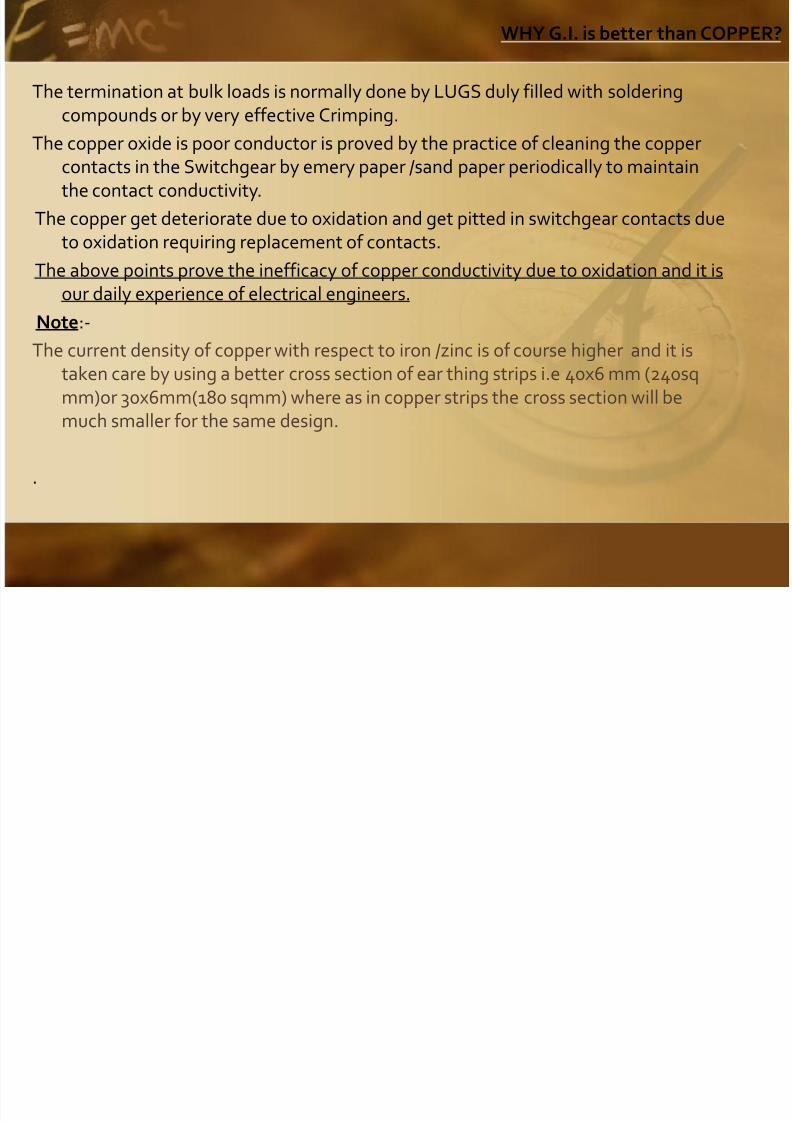
The termination at bulk loads is normally done by LUGS duly filled with solderingcompounds or by very effective Crimping.
The copper oxide is poor conductor is proved by the practice of cleaning the coppercontacts in the Switchgear by emery paper /sand paper periodically to maintainthe contact conductivity.
The copper get deteriorate due to oxidation and get pitted in switchgear contacts dueto oxidation requiring replacement of contacts.
The above points prove the inefficacy of copper conductivity due to oxidation and it isour daily experience of electrical engineers.
Note:-
The current density of copper with respect to iron /zinc is of course higher and it istaken care by using a better cross section of ear thing strips i.e 40x6 mm (240sqmm)or 30x6mm(180 sqmm) where as in copper strips the cross section will be
much smaller for the same design.
.

8/3/2019 Chemical Earthing 2011 FAQ
http://slidepdf.com/reader/full/chemical-earthing-2011-faq 19/99
How Earthing System Works?
An example of the chemical earthing as per the following specification which can becompared with the other systems for your analytical reference.
Our specs: e.g. Dia: 50mm
Length: 3000mm
Strip Size in the Pipe: 40x6mm
The Hollow pipe is filled with Chemical: Known as CCM (This is used to dissipate the
heat generated due to Phase to Phase and Phase to Earth fault Which is very high and cause of all electrical Hazards and fires)
GBFC: 45 Kilos which is used to maintain the moisture in the earthing system forits efficient working.
The electrode is installed 3 mtr deep and is surrounded by the 45 kilos of GBFC in thick
slurry to maintain the moisture level for long period of time. for the earthing system which you generally install.

8/3/2019 Chemical Earthing 2011 FAQ
http://slidepdf.com/reader/full/chemical-earthing-2011-faq 20/99
How Earthing System Works?
THREE PARAMETERS FOR SUCCESS OF EARTHING:-
A. capacity to clear the fault current- avoid electrical Hazards
B. To dissipate the heat – to avoid the failure of earthing system
C. To maintain the moisture level - to achieve the low ohmic values
ALFREDKIM Earthing meets the three parameters as under:
1) You will observe that success of the earthing depends on the capacity to carry the fault current .-We use 40x6mm G.I. strip surrounded by CCM which is Semi metal.
2) The heat is dissipated because of CCM filled in the pipe which has a meltingtemperature of 2500°c.
3) The GBFC has a property to absorb water 15 times of its weight and doesn’t dissolve in the water . It remains wet for a very long period of time.
CONCLUSION: All three important parameter are met by ALFREDKIM Earthing
system as explained above.We suggest that you please check on the above parameters

8/3/2019 Chemical Earthing 2011 FAQ
http://slidepdf.com/reader/full/chemical-earthing-2011-faq 21/99
How Earthing System Works?
Please Note:
1. The Right size of earthing system is necessary and will work satisfactorily. The
undersized earthing should be avoided for long term safety of installation. 2. Incase the fault current of full capacity takes place then the earthing system can
fail because of inadequate dissipation of heat which may result in to electric firesand other hazards to life and property.
3. The earthing is not taken as formality but as a necessity for electrical safety.
4. Our price of Rs. 7850.00/- (Exclusive of VAT) exclusive of installation and transport isworth paying for safety of the plant, machinery and building rather thencompromising with quality of earthing system.
5. Please consider the Price paid for this earthing as insurance for your Plant,Machinery and building and not as an expense.
6. A good Earthing will save your down time on repair, maintenance and loss of production hours.

8/3/2019 Chemical Earthing 2011 FAQ
http://slidepdf.com/reader/full/chemical-earthing-2011-faq 22/99
WHAT IS SYSTEMS OF GRID EARTHING?
Reasons of Grid Earthing: -
1. To manage very high fault currents So that the low ohmic value of earth resistance
will reduce the effective watt loss thereby controlling the heat generated in thesystem.
2. To maintain very low level of ohmic values of earth resistance like 0.1, 0.2 etc. sothat the sensitive electronic equipment don’t malfunction & there electronics cards& PCB’s don’t fail & get damage electrically.
System at a Typical Plant:-
1. The connected loads at the plant for each equipment are not heavy.
2. The reason for maintaining the value of low resistance is desirable for preventingthe malfunctioning of the electronic equipment & there electronic cards.

8/3/2019 Chemical Earthing 2011 FAQ
http://slidepdf.com/reader/full/chemical-earthing-2011-faq 23/99
WHAT IS SYSTEMS OF GRID EARTHING?
When four earthings are used in a GRID:-
CASE-I
R1=0.4, R2=0.6, R3=0.8, R4=1.21/R=1/0.4+1/0.6+1/0.8+1/1.2
1/R=2.5+1.67+1.25+0.833
1/R=6.25
R=0.16 ohms.
We have given two cases for each type of grid earthing i.e. three earth systems &four Earth systems.
CASE-II R1=0.5, R2=0.7, R3=1.0, R4= 1.2
1/R=1/0.5+1/0.7+1/1.0+1/1.21/R=2+1.43+1.0+0.831/R=5.26R=0.19 ohms

8/3/2019 Chemical Earthing 2011 FAQ
http://slidepdf.com/reader/full/chemical-earthing-2011-faq 24/99
WHAT IS SYSTEMS OF GRID EARTHING?
Our recommendations are for four earth systems to maintain a long term low ohmicvalues because of the following factors:-
1. Change of a soil condition for a period of a time is choosing a different location forthe earthing system in the same premise.
2. Change of climatic condition:
a. Extremely dry climate- SUMMER
b. Extremely cold climate- WINTER c. Extremely humid climate-RAINS
d. Occasionally scanty rain fall which is assumed to be less than 250mm in a year whichis unlikely in any geographical location.
Our recommendations are based on the effect that the equipment will work throughout the year in all climatic condition.

8/3/2019 Chemical Earthing 2011 FAQ
http://slidepdf.com/reader/full/chemical-earthing-2011-faq 25/99
Why Earthing Near To the Equipment?
Question: Should it be near to the point of application/Equipment or away from it?
Reason:
Please read on!
1. OLD TRADITIONAL SYSTEM:-
I) The conventional pit type copper plate Earthing with large Quantity of Charcoal &
Salt was requiring large area of about 4’x3’or 6’x4’ & depth used to be 20’ to60’ (7to 20 mtr)depending on the soil condition.
II) This much area was conveniently available in the factories/office premises in earlierdays when the space was not constraint.
III)The distance between the earth pit & the point of application used to be fewmeters may be 50-100mtrs & therefore to maintain the low resistance of the
earthing wire from the earth pit to the machinery the copper wire of 8/10 swg wasused.
8/3/2019 Chemical Earthing 2011 FAQ
http://slidepdf.com/reader/full/chemical-earthing-2011-faq 26/99
Why Earthing Near To the Equipment?
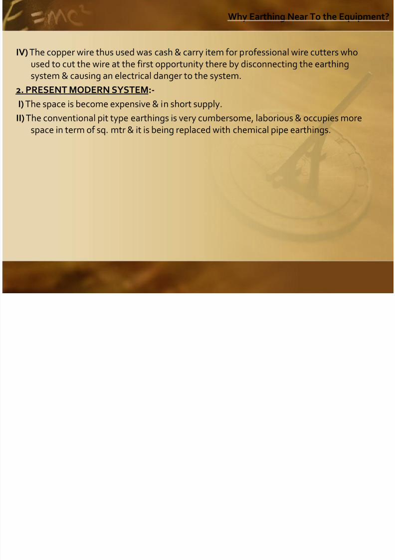
IV) The copper wire thus used was cash & carry item for professional wire cutters whoused to cut the wire at the first opportunity there by disconnecting the earthingsystem & causing an electrical danger to the system.
2. PRESENT MODERN SYSTEM:-
I) The space is become expensive & in short supply.
II) The conventional pit type earthings is very cumbersome, laborious & occupies morespace in term of sq. mtr & it is being replaced with chemical pipe earthings.
8/3/2019 Chemical Earthing 2011 FAQ
http://slidepdf.com/reader/full/chemical-earthing-2011-faq 27/99
Why Earthing Near To the Equipment?
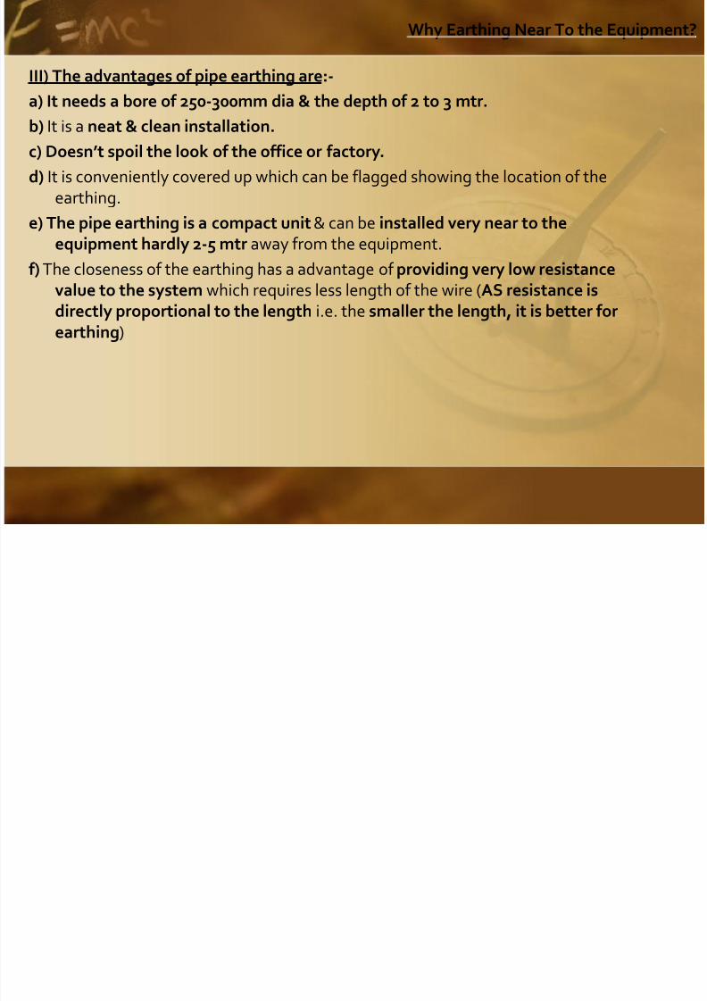
III) The advantages of pipe earthing are:-
a) It needs a bore of 250-300mm dia & the depth of 2 to 3 mtr.
b) It is a neat & clean installation. c) Doesn’t spoil the look of the office or factory.
d) It is conveniently covered up which can be flagged showing the location of theearthing.
e) The pipe earthing is a compact unit & can be installed very near to the
equipment hardly 2-5 mtr away from the equipment.f) The closeness of the earthing has a advantage of providing very low resistance
value to the system which requires less length of the wire (AS resistance isdirectly proportional to the length i.e. the smaller the length, it is better forearthing)
8/3/2019 Chemical Earthing 2011 FAQ
http://slidepdf.com/reader/full/chemical-earthing-2011-faq 28/99
Why Earthing Near To the Equipment?
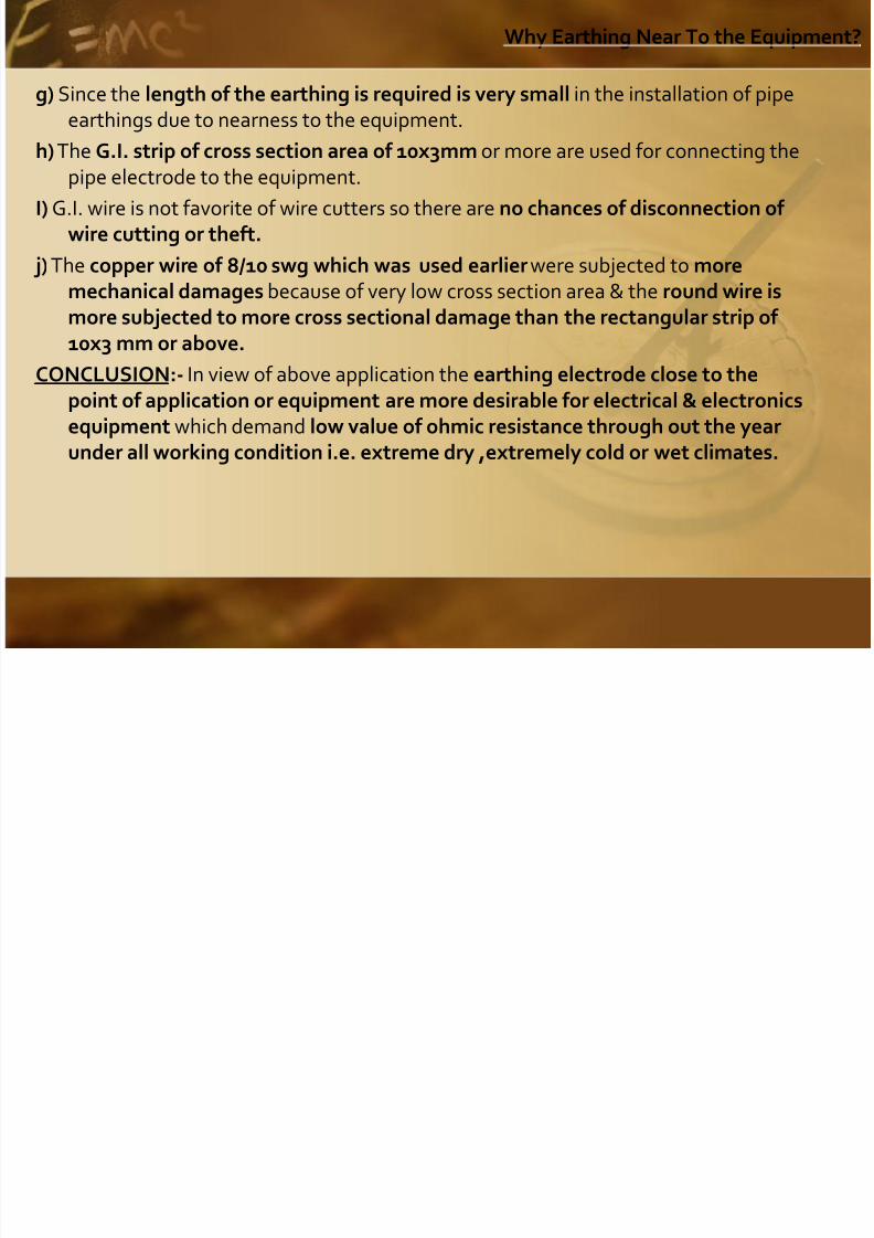
g) Since the length of the earthing is required is very small in the installation of pipeearthings due to nearness to the equipment.
h) The G.I. strip of cross section area of 10x3mm or more are used for connecting thepipe electrode to the equipment.
I) G.I. wire is not favorite of wire cutters so there are no chances of disconnection of wire cutting or theft.
j) The copper wire of 8/10 swg which was used earlier were subjected to moremechanical damages because of very low cross section area & the round wire ismore subjected to more cross sectional damage than the rectangular strip of 10x3 mm or above.
CONCLUSION:- In view of above application the earthing electrode close to thepoint of application or equipment are more desirable for electrical & electronicsequipment which demand low value of ohmic resistance through out the year
under all working condition i.e. extreme dry ,extremely cold or wet climates.

8/3/2019 Chemical Earthing 2011 FAQ
http://slidepdf.com/reader/full/chemical-earthing-2011-faq 29/99
WHY DISCARD PIT TYPE EARTHING?
The conventional copper pit type earthing is out of date because:-
1. The water level is going down at most of the geographical areas & therefore one
has to dig deep holes may be to the extent of 20-50 mtr. 2. The commonly used substances in pit type earthing were sodium Chloride known as
common salt, soft coke & charcoal.
3. The common salt (sodium chloride) is a hygroscopic substance & it gets dissolved inwater & losses its hygroscopic properties when become water itself.
4. The salt is known to be a corrosive electrolyte which decays the pipe and theconductor used for earthing. Due to decay one does not get the consistent ohmic values.
5. The soft coke & charcoal tend to become ash due to heavy heat generated byheavy electric fault currents generated in the system especially at higher voltagesat 1.1KV ,3.3KV 6.6kv, 11kv, 33kv, 66kv and 133kv transmission distribution
line & at substation.

8/3/2019 Chemical Earthing 2011 FAQ
http://slidepdf.com/reader/full/chemical-earthing-2011-faq 30/99
WHY DISCARD PIT TYPE EARTHING?
6. The heat generated is proportional to I2Rt (Time in seconds) e.g. if the faultcurrent of 10,000amps in the system with an earth resistance 2 ohms as
permitted by IS in 0.1 seconds is given as under. H=I 2Rt
H=10,000x10, 000x2x0.01=20, 00,000 calories =1053°C
This much heat generated in one fault. Assuming 6 faults in a year then in a periodof four year -24 faults occur, each fault generating 1053 °C & above.
7. Each fault of this magnitude will turn the soft coke/ charcoal into ash gradually in aperiod of 3-4 years. The earth system will deteriorate and give larger value of ohmicresistance thereby endangering the entire installation consequently people &
property .
8/3/2019 Chemical Earthing 2011 FAQ
http://slidepdf.com/reader/full/chemical-earthing-2011-faq 31/99
WHY DISCARD PIT TYPE EARTHING?
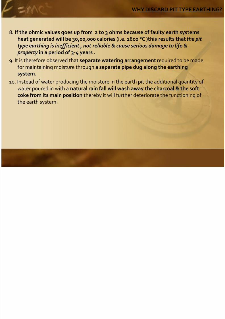
8. If the ohmic values goes up from 2 to 3 ohms because of faulty earth systems
heat generated will be 30,00,000 calories (i.e. 1600 °C )this results that the pit type earthing is inefficient , not reliable & cause serious damage to life & property in a period of 3-4 years .
9. It is therefore observed that separate watering arrangement required to be madefor maintaining moisture through a separate pipe dug along the earthingsystem.
10. Instead of water producing the moisture in the earth pit the additional quantity of water poured in with a natural rain fall will wash away the charcoal & the softcoke from its main position thereby it will further deteriorate the functioning of the earth system.

8/3/2019 Chemical Earthing 2011 FAQ
http://slidepdf.com/reader/full/chemical-earthing-2011-faq 32/99
WHY SWITCH TO CHEMICAL ELECTRODE EARTHING?
The above points conclude that pit type earthing is out of date and it is beingreplaced and preferred over chemical pipe earthing for reasons given below:-
1. The pipe for the chemical earthing are generally 2 mtr or 3mtr in length thereforethe earth bore need not more than the 250 to 300mm dia & maximum depth of 3mtr.
2. The moisture is maintained at a small depth of 3mtr by using ground enhancematerial, commonly known as GBFC (Grounding Back Fill Compound).
3. The efficacy of the chemical earthing to maintain the moisture which is essential forlow ohmic values of earthing resistance is due to use of hygroscopic chemical likealuminum silicate etc. which absorb the moisture but doesn’t get dissolved in thewater unlike salt.
4. The heat generated due to electric faults developing heat of 1060 °C and aboveis resisted by CCM (Crystalline Conducive Material) which can withstand upto
2500°C.

8/3/2019 Chemical Earthing 2011 FAQ
http://slidepdf.com/reader/full/chemical-earthing-2011-faq 33/99
WHY SWITCH TO CHEMICAL ELECTRODE EARTHING?
5. The CCM is filled in the pipe of appropriate dimension of 50mm or 80mm dia and sealed at both ends. It incorporates the earth conductor of GI strip of suitable
size of 30x6mm or 40x6mm depending upon the individual design of manufacturer.
6. The CCM filled in the pipe being a good conductor increases the fault currentcapacity of the system because the pipe is hollow but when filled with CCM it behaves like almost solid pipe.
7. The CCM resists cracking, warping, shrinking, or distortion even when temperature
exceed 2500 °C due to severe repeated electric faults which may happen inoperations over the year.
8. The GI pipe used are adequately galvanized (80-100 microns) as per IS -30471987.

8/3/2019 Chemical Earthing 2011 FAQ
http://slidepdf.com/reader/full/chemical-earthing-2011-faq 34/99
WHY SWITCH TO CHEMICAL ELECTRODE EARTHING?
9. Zinc oxide will be formed during the use of the earth system. Zinc oxide has following advantages over the conventional earthing which uses the copper
plate or copper conductors:- a) Zinc oxide so formed is insoluble in water.
b) Zinc oxide has a unique Dielectric strength that exhibits semiconducting &piezoelectric dual properties. (Unlike in copper where the copper oxide is a badconductor of electricity & becomes powdered Red Oxide (Copper Oxide) underhigh fault current that generate high temperatures)
c) ZnO finds application in Varistors which are used to prevent voltage surges in theelectronic devices like mobile phone.
d) ZnO is not combustible & used as a fire extinguishant material.
CONCLUTION:- The industry, project managers & the electrical consultants find it
very convincing to use & specify the chemical pipe earthing which is convenient toinstall, no maintenance what so ever with a long life of over 15 years.

8/3/2019 Chemical Earthing 2011 FAQ
http://slidepdf.com/reader/full/chemical-earthing-2011-faq 35/99
Why Control Floating Neutral Voltage?
1. All Neutral should have Zero Potential Difference.
2. Why Neutral Voltage is Noticed Now a Days.
Reasons for Neutral voltage:A. The use of electronic equipment /ups/computers /CFL lamps/Speed drives etc.
These devices on operate at different cut off voltages in the sine wave cycle andhence the sine wave is distorted resulting in the higher PD in the Neutral andcause the flow of currents in the Neutral Circuit which results in the damage of PCB cards and other sensitive components in the electronic circuit/equipments
B) The Industrial loads are in general Not Balanced Loads and therefore the linevoltages are spill over to Neutral which results into stray currents therebydamaging the electronic equipments/ PCB cards

8/3/2019 Chemical Earthing 2011 FAQ
http://slidepdf.com/reader/full/chemical-earthing-2011-faq 36/99
Why Control Floating Neutral Voltage?
Why Neutral Grounding.
A. To maintain the ZERO PD between the Neutral and earth and to ground the Spill
over voltages the Neutral is grounded.It is therefore very necessary to immediately connect Neutral to the Earth by Solid
Permanent contact so that there is no possibility of loose connection/disconnection at any stage OF OPERATION to prevent any electrical mishaps.
Method of testing the New Earth Electrode
A) Connect the New Electrode to the Neutral of Supply Line by very Good secureConnection Either Bolted or soldered.
B) Connect the Volt meter as shown in the Picture (P1) below.,
C) When the Neutral is properly grounded and the earthing is Successful the voltmeter should give Nearly ZERO voltage between Earth and Neutral

8/3/2019 Chemical Earthing 2011 FAQ
http://slidepdf.com/reader/full/chemical-earthing-2011-faq 37/99
Why Control Floating Neutral Voltage?
D) Electricity finds always easier path to flow therefore the spill over voltage in the
neutral will go to the newly installed earth electrode. In case earthing is notsuccessful or has higher ohmic value of resistance or loose contact/ disconnectionin the earthing circuit the voltmeter will show the undesirable voltage. In case theearthing is ok and correctly done the voltmeter will show almost Zero Volts.
Kindly follow the above testing methods and ensure the testing is properly done.
l i l id

8/3/2019 Chemical Earthing 2011 FAQ
http://slidepdf.com/reader/full/chemical-earthing-2011-faq 38/99
Two Electrical Accidents
1. Pak diplomat electrocuted by faulty hair dryer in Delhi
7 October 2009
Rahul Tripathi | TNN
New Delhi: An unfortunate act of carelessness claimed the life of a 49-year-old Pakistani
diplomat in the capital on Sunday straight out of a bath, Mohabat Khan Afridi had tried to
use a defective hair dryer, leading to fatal electric shock.
Afridi, who lived in DBlock , Vasant Vihar in south Delhi, was the political counsellor at the
Pakistan High Commission since 2007. He is survived by his wife and three children. Afridi
was a native of Kohat in Pakistans North West Frontier Province.On Sunday night, the diplomat went for a bath, carrying his hair dryer along. His wife told us
that the hair dryer was damaged and used to give out electric shock about which she had
warned Afridi. It appears that after the bath, Afridi was using the dryer when he was
electrocuted around 8.30pm. He might have tried to raise an alarm but since the bathroom
door was locked, no one heard him, said a police officer.
The body was discovered around 10.30pm by Afridis wife, Fahima, and other staff at their
ground floor house. They went to check in his bedroom when he was not seen for a long timeand found the bathroom locked from inside . When there was no response on knocking, they
broke down the door and found him lying on the floor. They immediately took him to Fortis
hospital, said the officer. Doctors, who declared him brought dead, said Afridi had died due
to electrocution and there were no apparent injuries on his body.
T El t i l A id t

8/3/2019 Chemical Earthing 2011 FAQ
http://slidepdf.com/reader/full/chemical-earthing-2011-faq 39/99
2. The Case of Stray Voltage in a Lake
October 1, 2009 By Donald R. Johnson, P.E., Johnson Engineering
Faulty concentric neutrals on high voltage underground cables was the cause of one
drowning death and brain injury to two others while swimming in a lake.
Stray voltage is a popular term resulting from electrical currents flowing through the earth,or other conductive surfaces not normally expected to carry electric currents. Small amounts
of electric currents travelling through the earth are prevalent throughout the nation primarily
due to electric utilities using the earth as a grounding medium for grounded wye distribution
systems. Even though these grounded wye systems do carry a neutral conductor returncurrent path since the neutral conductor is grounded to the earth at multiple locations, (as
required by the NESC), the result is the earth is a parallel path for these currents. Typically,depending upon the conductivity of the earth and the amount of return neutral current on
the electric distribution system, the amount of current flowing through the earth is small. As
electric loads across the nation continue to increase, these earth currents are also
increasing. These earth currents became noticeable many years ago on dairy farms. The
dairy farmers noticed a significantly higher mortality rate among the dairy cows along with amajor loss of milk production. The culprit was directly tied to the amount of earth currentsflowing through the dairy facilities. Electric utilities across the nation have found out the
hard way (through multi-million dollar lawsuits) that they must reduce these earth currents
to non-damaging levels.
Two Electrical Accidents
T El t i l A id t
8/3/2019 Chemical Earthing 2011 FAQ
http://slidepdf.com/reader/full/chemical-earthing-2011-faq 40/99
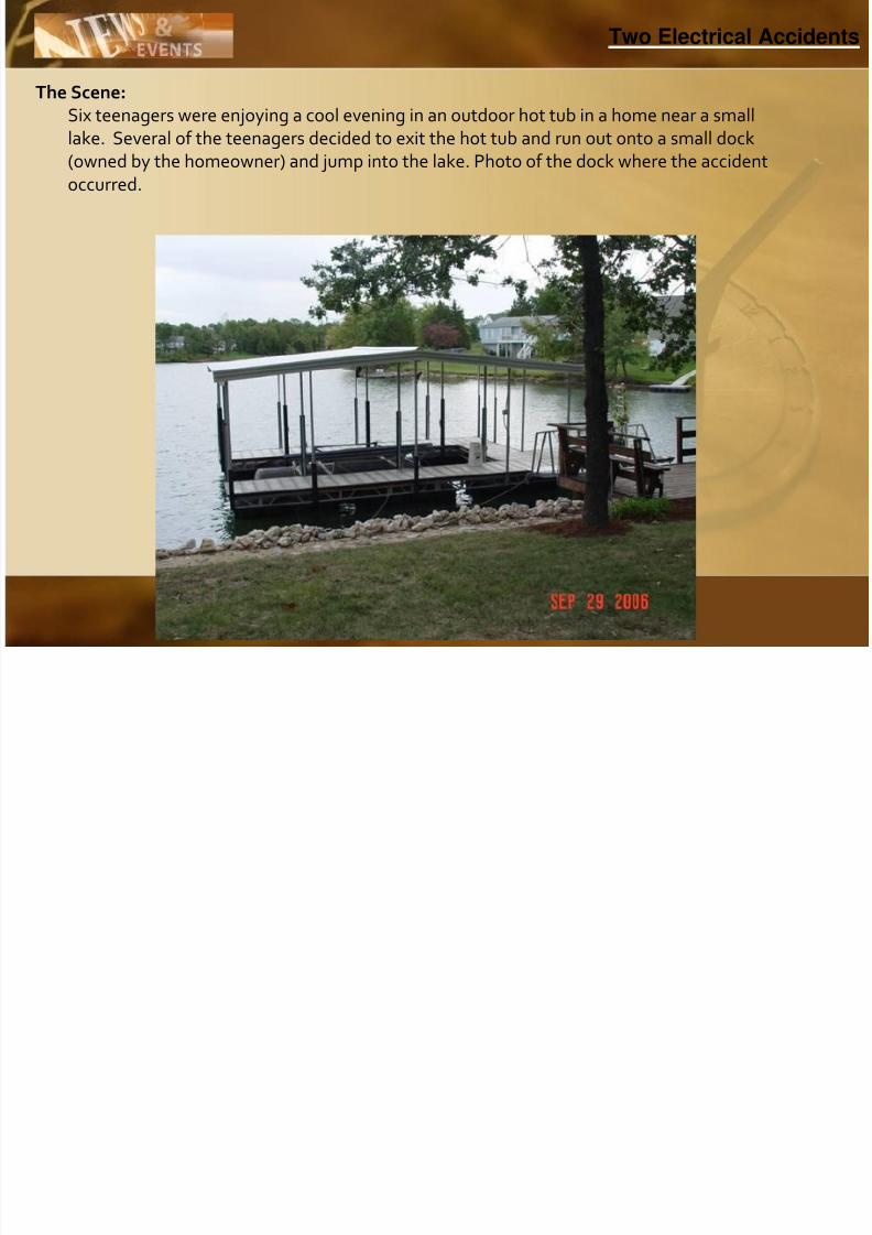
The Scene:
Six teenagers were enjoying a cool evening in an outdoor hot tub in a home near a small
lake. Several of the teenagers decided to exit the hot tub and run out onto a small dock
(owned by the homeowner) and jump into the lake. Photo of the dock where the accidentoccurred.
Two Electrical Accidents
T El t i l A id t

8/3/2019 Chemical Earthing 2011 FAQ
http://slidepdf.com/reader/full/chemical-earthing-2011-faq 41/99
The Accident: The teenagers were swimming near the dock for several minutes when they beganto notice electric currents flowing through their bodies. One boy who experiencedthe phenomena at the site describes the currents as causing him to lose musclecontrol such that he could no longer swim and he began sinking in thewater. Several of the teenagers that were on the dock saw the swimmingteenagers’ plight and called to the adults in the house for help. Several of theadults came running out, called 911, and began diving into the water trying to
retrieve the teenagers that were under the water (Note: It was determined duringlater testing that the currents in the water were intermittent thus not causingdamage to the adults.). After multiple dives the adults were able to retrieve thetwo boys and one girl that were under the water. CPR was immediatelyadministered until the paramedics arrived. After the three were taken to thehospital the outcome was that one boy drowned and the other boy and girl
received brain damage due to lack of oxygen caused by near-drowning.
Two Electrical Accidents
T El t i l A id t

8/3/2019 Chemical Earthing 2011 FAQ
http://slidepdf.com/reader/full/chemical-earthing-2011-faq 42/99
The Investigation: The first thoughts by those at the scene after the accident was that the dockwiring was somehow faulty which caused the electric current to be in thewater. My services as a professional electrical engineer were then engaged byattorneys representing the plaintiffs (who filed suit against the electric utility andothers) to try to determine the cause of the electric currents in the lakewater. After numerous investigations by me and other experts, it was determined
that the dock wiring was not the cause of the electric currents in the lake water. Ilater determined through discovery from the electric utility that they had majorcorrosion problems with the bare concentric neutrals of their high voltageunderground cables that were buried under and around the lake where theaccident occurred.
Two Electrical Accidents
Two Electrical Accidents

8/3/2019 Chemical Earthing 2011 FAQ
http://slidepdf.com/reader/full/chemical-earthing-2011-faq 43/99
The electric utility realized up to nine years prior to the accident, throughconcentric neutral testing procedures, that the bare concentric neutrals were in aserious state of deterioration throughout the lake area and the housing subdivisionaround the lake. Even though the electric utility realized the problems they werehaving with the deteriorated concentric neutrals in the area they didn’t seem torealize the importance of immediately fixing the problem. They began a multi-year program of replacing the bare concentric neutral cables with new jacketedconcentric neutral cables in the area. However due to difficulty in installing new
cable in two particular sections of underground cable under and around the lake,these sections were not replaced. It turned out that these two particular sectionsof underground cable that were not replaced were the primary paths for theneutral current return for the entire lake area subdivision back to the electric utilitysubstation source. The result was that the electrical load within the subdivisionwas essentially on an “island” in terms of an adequate return current
path. Because of this “island” effect the currents took the least resistant path intothe lake water heading to the dock which was more than adequately grounded tothe electric utility system overhead neutral which was then tied directly to theutility substation source.
Two Electrical Accidents
Two Electrical Accidents

8/3/2019 Chemical Earthing 2011 FAQ
http://slidepdf.com/reader/full/chemical-earthing-2011-faq 44/99
To verify the above scenario numerous tests were completed by me during severalsite visits. During one visit a Fluke Model 289 recording multimeter was installedat the dock where the accident occurred and left to record for eight to tenconsecutive days (The wiring to the dock was totally disconnected and removed atthis time.). The voltages were recorded by placing a ground rod off the end of thedock into the lake water where one meter probe was attached. The other meterprobe was attached to the house ground which was in turn attached to the electricutility ground. A 500-ohm shunt resistor was included in the voltage measuring
circuit. The currents were measured using the same technique however the 500-ohm resistor was placed in series with the circuit.
Two Electrical Accidents
Two Electrical Accidents

8/3/2019 Chemical Earthing 2011 FAQ
http://slidepdf.com/reader/full/chemical-earthing-2011-faq 45/99
The results of the testing indicated that both the voltage and current levels followed the
electric loads of the utility in that the load peaks were at the highest levels during the
morning and evening hours (Note that the accident occurred during the evening hours when
electric loads were at the highest.). In addition the frequency of all voltage and currentmeasurements were measured at 60 Hz. This was a direct indication that the electric utility
was the source of these measured voltages and currents. The highest currents measured
during this test period reached .5 amperes and the highest voltage reached 6.2 volts.
During another visit to the site, with the electric utility present to allow access to their
underground cable junction enclosures, numerous readings were conducted to measure thecurrent on both the underground electric utility energized phase conductors and theconcentric neutrals. Voltage measurements were also taken from the ground system in the
enclosures to a remote ground. The results indicated that indeed the concentric neutrals in
the two particular critical sections were likely non-existent. In one particular section right
near the lake the neutral current on the concentric neutral was less than one-tenth of an
ampere whereas the energized phase current was in excess of 6 amperes. Obviously the
remainder of the return current was flowing through the earth and in this case the lakewater. In addition the voltage measured from these same junction enclosures was in excess
of 7 volts to a remote ground rod. These measurements were a clear indication that the
concentric neutrals on these underground sections were likely absent due to corrosion.
Two Electrical Accidents
Two Electrical Accidents
8/3/2019 Chemical Earthing 2011 FAQ
http://slidepdf.com/reader/full/chemical-earthing-2011-faq 46/99
The Conclusion: Using an assumed human body resistance of 300ohms1 when immersed in freshwater and assuming a current range through the human body where musclecontrol is lost in the range of 6 to 30 milliamperes2 using Ohm’s law the voltagenecessary to cause a drowning in fresh water is in the range of 1.8 to 9 volts, 60 HzAC. The above testing results show that the necessary voltage and current levelswere at a level well within the range to cause the drowning and near-drowning of the victims of this case.
This case went to a trial by jury and the jury awarded the plaintiffs a total judgment of $2,325,000. No appeal was filed by the electric utility defendant.
This case shows the dramatic effects of stray voltage especially in an area wherepeople are exposed to stray voltages when in a wet environment. Electric utilitiesmust be vigilant in maintaining their distribution systems such that stray voltagesare kept at extremely low levels such that humans and animals alike are not
exposed to these dangers. As electric loads continue to increase across the nationmany experts are even encouraging electric utilities to modify their distributionsystems so that the earth is not used as a current carrying medium.
Two Electrical Accidents
Floating (NE) Neutral to Earth Voltages Causes and Remedies

8/3/2019 Chemical Earthing 2011 FAQ
http://slidepdf.com/reader/full/chemical-earthing-2011-faq 47/99
Floating (NE) Neutral to Earth Voltages–Causes and Remedies
Stray voltages or neutral-to-earth (NE) voltages are an on going problem in manyareas supplied from single phase and Multi-grounded services and where
current levels on the grounding systems are above the perception threshold foreither animals or humans. Typical locations are clusters of medium and largescale industries dairy farms, feeder and confinement operations, swimming pools,water Systems, residences, etc. Stray voltages (NE) can come from manysources, both from on and off the site. In most cases, the problems are the resultof several simultaneous sources combined.
On-site stray voltage can usually be resolved through a program of upgrading andreconnecting the wiring system and its various loads. Off-site stray voltage, whichis of particular interest to the power supplier, can result from primary neutralcurrents, off-site faults, marginal grounding, etc. of-day also adding to theconfusion. Although it may go away, there can be no assurance that it will cause
it. A loose neutral connection can cause a stray voltage or even a fault at anotherservice may cause it. In many cases, a poor primary neutral connection ismasked by the grounding system of the customer, giving no obvious signs of aproblem even existing unless a stray voltage check is made. This is a neutral-to-earth voltage and can easily be measured with and volt meter and a remoteground.
STRAY VOLTAGES:

8/3/2019 Chemical Earthing 2011 FAQ
http://slidepdf.com/reader/full/chemical-earthing-2011-faq 48/99
STRAY VOLTAGES:
Electrical engineering specialists have known for some time that low non-lethalvoltages accessed to dairy animals can cause mastitis, affect animal behavior andmaterially reduce milk production. More recently, the same voltages have beenknown to cause problems in industries, computerized equipments, parlors, poultryhouses, water fountains, swimming pools and homes.Various studies have shownthat voltages about 0.5 volts can be detected by animals that are very wet as is adairy cow being washed down prior to milking. There is some evidence that
humans are susceptible to a threshold voltage of approximately1 volt when theyare wet. Thus voltage below 10 volts, which previously the electrical industry has largely ignored as a non-problem, now, has a much greater interest and appreciation. Since these low voltages may now have many sources, they have been variouslycalled “tingle voltage”, extraneous voltage, or more generically called Stray
Voltage. A number of studies and findings have identified methodical and logicalmethods for identifying the sources of the problems and eliminating them.
ON-SITE:

8/3/2019 Chemical Earthing 2011 FAQ
http://slidepdf.com/reader/full/chemical-earthing-2011-faq 49/99
ON-SITE:
On-site voltages caused by on-site wiring problems and electrical equipmentdefects can readily be isolated by turning the service entrance switch off. Thenoperation of individual circuits and pieces of equipment can identify specificProblems. Examples would be failed water heater elements, defective electricMotors and pumps, broken or damaged wiring insulations, etc.
The portion of the voltage that remains on the ground system after the service
Entrance main is turned off is obviously off-site in origin. However, neutral-to earthVoltage which increases with on-site load may also be considered off-site innature if it is due to the increased load on the primary neutral. This phenomenoncan lead to confusion when attempting to resolve the overall problem. Basically,All on-site problems can be eliminated with proper wiring and associated Goodwiring and equipment practices.
OFF-SITE:

8/3/2019 Chemical Earthing 2011 FAQ
http://slidepdf.com/reader/full/chemical-earthing-2011-faq 50/99
OFF-SITE:
There can be several sources of voltages that originate off-site. Regardless of theSources, the stray voltage must be identified and eliminated. Common off-sitesources include power supplier neutral, telephone ground, cable television,cathodic Protection on buried pipelines and even faulty electrical equipment onanother site by far the most common off-site source is the power supplier neutral.It is often the entire source of stray voltage, in other instances; it may becontributing only a portion of the stray voltage. However, this neutral primary
current caused contribution may well be above the 0.5 volt threshold and must beeliminated by appropriate safe and cost effective methods.
SOURCE OF POWER SUPPLIER NEUTRAL-TO-EARTH VOLTAGE

8/3/2019 Chemical Earthing 2011 FAQ
http://slidepdf.com/reader/full/chemical-earthing-2011-faq 51/99
SOURCE OF POWER SUPPLIER NEUTRAL-TO-EARTH VOLTAGE
It seems to be common practice that electric power suppliers utilize amultigrounded distribution system. Both three and single-phase power lines areequipped with a neutral to return current back to their substation. Even three-phase lines cannot be balanced to eliminate all current flow on the neutral. Even ifthey were expertly balanced, the addition of single-phase load would cause animbalance. Electric current requires a change in voltage commonly called voltagedrop in order to push it along a conductor. As load on the line builds, there will be
a proportional increase in voltage. Thus there is a small voltage usually presenton power line neutrals. While is does not normally represent and lethal hazard, itmay cause problems in highly sensitive situations like computerized equipments ,servers, ups, vfd , eapbx,automated computerized machine tools , graphic designand printing machines and milk dairys, parlor or a swimming pool.
SOURCE OF POWER SUPPLIER NEUTRAL-TO-EARTH VOLTAGE
8/3/2019 Chemical Earthing 2011 FAQ
http://slidepdf.com/reader/full/chemical-earthing-2011-faq 52/99
SOURCE OF POWER SUPPLIER NEUTRAL TO EARTH VOLTAGE
Since the power line neutrals are grounded at every service, every transformer,and at least four times per mile, it becomes quite evident that voltage on theprimary neutral will vary as the load varies and as the electrical resistance of thegrounding electrodes change. The resistances of the grounds change as soilmoisture changes. An example is the grounds lose their conductivity as theground dries out in dry weather(summers and winters) and regains it as moistureis added during rainy conditions.The greatest electrical loads occur in severe
temperature conditions, typically on a hot dry summer day. This is just the timethe neutral grounding system has its lowest current carrying capacity therebyincreasing the voltage on the neutral. The result is that voltage problems frompower line neutrals can appear and go away in a seemingly mystical fashion.Also, load on the line almost always varies with time-
THE INTERCONNECTION PROBLEM
8/3/2019 Chemical Earthing 2011 FAQ
http://slidepdf.com/reader/full/chemical-earthing-2011-faq 53/99
THE INTERCONNECTION PROBLEM
Electric Power distribution systems normally require the primary neutral and thesecondary neutral to be interconnected for two reasons.
1. The interconnect provides an alternate path for current flow in the eventthese is a failure in the transformer. This alternate path assures that thePrimary fuse will blow if for example, the primary should drop into theSecondary.
2. The interconnect also provides access to site grounding to helpdissipate lightning. However, the interconnect applies any voltage on the primaryneutral to the secondary neutral. The voltage will follow the secondary neutralinto the service entrance panel neutral bar, through the bonding jumper requiredby the electric supply company, to the equipment grounding bar and from there toevery piece of grounded electrical
Equipment in the facility. We shouldn’t be surprised to find primary neutralto-Earth voltage in our buildings, because we go to great lengths to put itthere.
ISOLATION OF NEUTRALS
8/3/2019 Chemical Earthing 2011 FAQ
http://slidepdf.com/reader/full/chemical-earthing-2011-faq 54/99
ISOLATION OF NEUTRALS
The electrical system would be fine if the interconnection of the primary andsecondary Neutrals were removed. This would eliminate any voltage enteringfrom the primary neutral. But this is not permitted, since it would allow apotentially dangerous situation’s Since a normally configured and properly wired distribution system almost neverhas neutral-to-earth voltages in excess of 6/8 volts, it can be blocked by virtuallycreating open circuit , “blocking” the neutral-to-earth voltage from entering acustomer’s Service. If the neutral-to-earth voltage is over 11 volts, either a fault or otherfailure has occurred and it acts as a short circuit, connecting the neutralFor safety with the impedance in “shorted” mode.
ADDITIONAL EARTHING OF LITTLE HELP

8/3/2019 Chemical Earthing 2011 FAQ
http://slidepdf.com/reader/full/chemical-earthing-2011-faq 55/99
ADDITIONAL EARTHING OF LITTLE HELP
A typical response when encountering –off-site stray voltage is to drive anadditional earthing on the premises. Please consider the numerous earth
stations along the multi-grounded distribution system; the addition of even
a few additional grounds is not likely to materially reduce the voltage. In
actuality, if the entire grounding complex were duplicated the voltage would
only be reduced by a magnitude of one-half.
The equipotential plane has been used in industries or other loads for protectionwithin a small confined area. It does nothing to eliminate source and correctsnothing in the connected loads etc.
ADDITIONAL EARTHING OF LITTLE HELP

8/3/2019 Chemical Earthing 2011 FAQ
http://slidepdf.com/reader/full/chemical-earthing-2011-faq 56/99
ADDITIONAL EARTHING OF LITTLE HELP
A typical response when encountering –off-site stray voltage is to drive anadditional earthing on the premises. Please consider the numerous earth stations along the multi-grounded distribution system; the addition of even a few additional grounds is not likely to materially reduce the voltage. In actuality, if the entire grounding complex were duplicated the voltage would only be reduced by a magnitude of one-half.
The equipotential plane has been used in industries or other loads for protectionwithin a small confined area. It does nothing to eliminate source and correctsnothing in the connected loads etc.
Why water new earth bore?

8/3/2019 Chemical Earthing 2011 FAQ
http://slidepdf.com/reader/full/chemical-earthing-2011-faq 57/99
y
When the pipe earthing /chemical earthing/maintenance free earthing/Gel earthing orwhatever name it is called by various manufacturers the watering of the bore isnecessary for the following reasons.
a. Unlike pit earthing where the salt (Nacl) & coal is used with copper plate, the pit isdug very deep approximately 40ft to 70 ft. depending on soil conditions where thedampness/moisture is achieved at various level of depth.
b. In case of the modern type of earthing which is free from future maintenance .Thewatering of the bore prior to installation is necessary for the following reasons.
1. The depth of the bore is either 2m/3m (6ft/10ft) which is much less than the normaldepth required in pit earthing.
2. The diameter of the bore is also limited to 200/300mm against the pit earthingwhich is almost in square meters.
Why water new earth bore?

8/3/2019 Chemical Earthing 2011 FAQ
http://slidepdf.com/reader/full/chemical-earthing-2011-faq 58/99
y
3.Unlike salt which is used in pit earthing which dissolves in water and salt it self becomes water in the course of time and dries it self, thereby loosing theconductivity in surrounding of the pit. Salt itself reacts with copper & makescopper chloride & other corrosive chemicals which corrode the copper plates.
4. The GBFC used by us absorbs the water upto 13 to 15 times its weight & dosen’tdissolve in the water therefore it retains its moisture property upto the lifetime of the electrode which is more than 25 years as it contains soil friendly materials.
5. Since there is no need to recharge the pit as the GBFC will remains moist through
out the life, therefore it is desirable and absolutely necessary to keep watering thebore for three to four days continuously before installing the electrode and filling itwith GBFC so that the GBFC will have moist bore available with enough watersoaked in the bore due to continuous watering before installation.
Why water new earth bore?

8/3/2019 Chemical Earthing 2011 FAQ
http://slidepdf.com/reader/full/chemical-earthing-2011-faq 59/99
y
6. After the installation no watering is necessary for future maintenance in whatever
soil condition it has been installed either indoor or outdoor installation.7. The earthing is quite successful in the normal climatic condition where the average
rain fall in a year may not exceed 250mm. This will give enough moisture to thesoil.
8. This earthing is being recommended by most of the consultant in desert areaswhere there is scanty rain fall in desert areas where the water level to achieve thenormal dampness is very-very deep.
9. Since we are able to achieve required dampness in a depth of 2 to 3meters withcontinuous watering of the bore &adequate quantity of the GBFC filled at the timeof earthing which remains moist for the rest of life & maintains the good ohmicvalues of earth resistance.
10.To conclude the old copper pit type earthing is out of date & maintenance freeearthing is easy to install, occupies less space & economical in the long run.
How is price comparable Cu V/s Chemical Earthing?

8/3/2019 Chemical Earthing 2011 FAQ
http://slidepdf.com/reader/full/chemical-earthing-2011-faq 60/99
p p g
Electrode Earthing System
Details of Costing:
Please Note Copper Used Is Electrolytic copper
Coal Used Is A-Grade (Coke)
Salt Used Is Rock Salt Superior Quality
Salt & Coke Used in Ratio of 1/1 to maintains desired level of moisture
How is price comparable Cu V/s Chemical Earthing?
8/3/2019 Chemical Earthing 2011 FAQ
http://slidepdf.com/reader/full/chemical-earthing-2011-faq 61/99
p p g
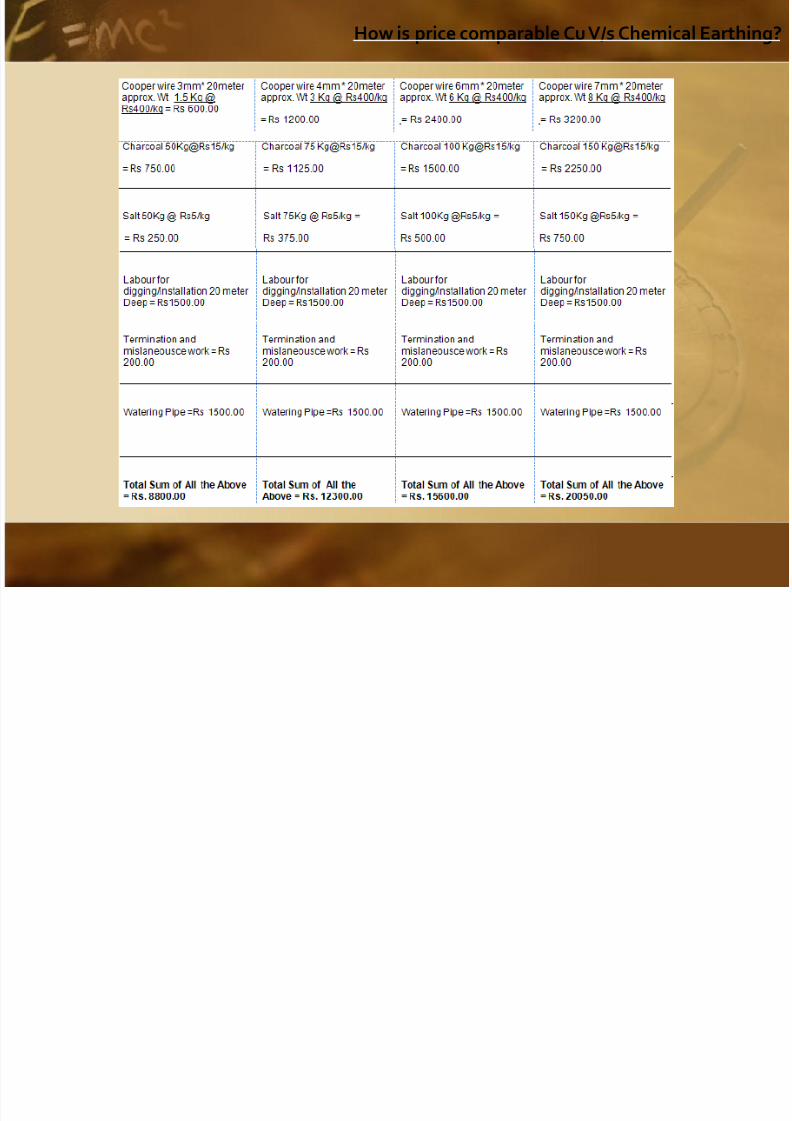
How is price comparable Cu V/s Chemical Earthing?

8/3/2019 Chemical Earthing 2011 FAQ
http://slidepdf.com/reader/full/chemical-earthing-2011-faq 62/99
p p g
Conclusion: In brief we can conclude:1) Chemical pipe earthing is much more economical,2) Easy to install,3) Occupy less space,4) Can be installed near to the equipment,5) Needs no maintenance,
6) Expected life
HOW TO SELECT & INSTALL ALFREDKIM EARTHGING SYSTEM?

8/3/2019 Chemical Earthing 2011 FAQ
http://slidepdf.com/reader/full/chemical-earthing-2011-faq 63/99
The chemical earthing system is provided in the form of electrode of G.I Pipes of different lengths & diameterof the pipe.
The annexure A, B, C and D are attached on page no.8-11 giving the dimensional details.
The selection of earthing system:Earthing will be selected on the basis of expected fault current in the installation that is depending upon
following factors-
1) Connected load
2) Capacity of D.G. Set
3) Capacity of Transformer
4) Factor of safety taken into consideration by design engineers & project managers handling the project
5) Calculation of fault current is done as under on the type of faults mentioned below:-
a) Fault can be either Phase-to-Phase
b) Fault can be Phase-to-earth/neutral
Calculations are based on full load current 1.4 amp/kVA under normal power factor in the system
Impedance level generally taken are 5% of the capacity therefore the fault current will 20% times of transformer on the secondary side (e.g. 100 kVA transformer will have full load of 140 amp and therefore
expected fault current in the worst condition of fault happening on the immediate secondary of thetransformer and hence the fault current will 2800 amps
The fault at the point of installation of equipments will get reduced depending on the distance of distribution of transformer and hence impedance of length of cable will come into play & fault current can be calculatedupon the size of length of cable used, on the common sense approach and practical experience of theproject managers
HOW TO SELECT & INSTALL ALFREDKIM EARTHGING SYSTEM?

8/3/2019 Chemical Earthing 2011 FAQ
http://slidepdf.com/reader/full/chemical-earthing-2011-faq 64/99
The chemical earthing system is provided in the form of electrode of G.I Pipes of different
lengths & diameter of the pipe.
The annexure A, B, C and D are attached on page no.8-11 giving the dimensional details.
The selection of earthing system:
Earthing will be selected on the basis of expected fault current in the installation that is
depending upon following factors-
1) Connected load
2) Capacity of D.G. Set
3) Capacity of Transformer
4) Factor of safety taken into consideration by design engineers & project managers handling the
project
HOW TO SELECT & INSTALL ALFREDKIM EARTHGING SYSTEM?

8/3/2019 Chemical Earthing 2011 FAQ
http://slidepdf.com/reader/full/chemical-earthing-2011-faq 65/99
5) Calculation of fault current is done as under on the type of faults mentioned below:-
a) Fault can be either Phase-to-Phase
b) Fault can be Phase-to-earth/neutral
Calculations are based on full load current 1.4 amp/kVA under normal power factor in the system
Impedance level generally taken are 5% of the capacity therefore the fault current will 20% times
of transformer on the secondary side (e.g. 100 kVA transformer will have full load of 140 amp
and therefore expected fault current in the worst condition of fault happening on the
immediate secondary of the transformer and hence the fault current will 2800 amps
The fault at the point of installation of equipments will get reduced depending on the distance of
distribution of transformer and hence impedance of length of cable will come into play &fault current can be calculated upon the size of length of cable used, on the common senseapproach and practical experience of the project managers
How to select size number of earthing for an Industry

8/3/2019 Chemical Earthing 2011 FAQ
http://slidepdf.com/reader/full/chemical-earthing-2011-faq 66/99
Type of Industrial loads :
1. Heavy industrial motors say 50 kw and above to run certain processing
machines in sugar, Paper, steel, textile, and heavy industries , arc/blastfurnaces etc, EOT cranes,Passenger /goods lifts, material equipment i.econveyers
2. The work shop machinery less than 50 kw including FHP motors i.e lathemachines, drilling machines, grinding machines, Hack saw machines,
shearing, cutting and bending machines, power /hydraulic presses,injection molding machines. Portable tools and other such lightmachinery. and water pumps
3. The CNC machines, Speed drives (Vfd etc) and other technologicaladvanced computerized equipment
4.Industrial lighting loads. A. mercury vapor lamps, sodium lamps Cfl lampsincandescent and fluorescent tubes , general purpose fans and industrialexhaust fans.
5 Air conditioning plants , ventilation equipment etc
How to select size number of earthing for an Industry

8/3/2019 Chemical Earthing 2011 FAQ
http://slidepdf.com/reader/full/chemical-earthing-2011-faq 67/99
6. Servers , large nos computers in net work controlled through online UPS systems
7. DG sets for stand by supply
8.Ditribution Transformers or Step up /Step down transformers.
9. Servo Voltage stabilizers, isolation transformers , ACB`s , Change over switches andother such controlling and protective devices.
How to select size number of earthing for an Industry

8/3/2019 Chemical Earthing 2011 FAQ
http://slidepdf.com/reader/full/chemical-earthing-2011-faq 68/99
a. The Individual body earthing is recommended for EOT cranes, Lifts,arc/Blast furnaces, conveyers systems
b. Other motors can be connected in parallel with common main earthing
, Precautions must be taken that distance covered is not vey long sothat circuit impudence is not increased causing high earth resistance .In such case the the experience of the engineer in charge is veryimportant to decide on the distance. We can recommend more thantwo conductors to run in parallel with proper termination of joint and
good quality of nuts, bolts, spring washers and flat washers.. To avoidrusting of joints it is suggested to use the stain steel hardware andgood quality of fasteners to avoid loose /weak joints
c. The above precautions are to be observed in machinery listed in Para2 for workshop machinery etc.
d. The earthing for the fixtures of the lighting equipments can be earthedin parallel with single earthing keeping the precaution termination of joints and taking that weak /loose joints are strictly avoided. It is notnecessary to provide double earthing or two earthing in parallel simplybecause engineering department cannot ensure reasonably strong and
electrically good joints
How to select size number of earthing for an Industry

8/3/2019 Chemical Earthing 2011 FAQ
http://slidepdf.com/reader/full/chemical-earthing-2011-faq 69/99
e. Cnc machines and other computerized equipment as per manufacturers’recommendation. One must use separate earthing for the body and neutral .neutral earthing is is Compusory for controlling FLOATING neutral voltageswhich might other vise damage the electronic PCB `s in the equipment
f. For DG sets , transformers ,and severs /ups systems 2 nos. earthing arenecessary for body and neutral . The is 3043 -1987 is clear on this concept
g.The separate single earthing is necessary for the body and neutral of the
protective equipment
A CONCLUSION! Why Chemical Earthing is more DURABLE AND RELIABLE?

8/3/2019 Chemical Earthing 2011 FAQ
http://slidepdf.com/reader/full/chemical-earthing-2011-faq 70/99
Why Chemical Earthing is more DURABLE AND RELIABLE?
1. LIFE OF EARTHING SYSTYEM:-
A.COPPER PLATE :-
1. The conventional copper pit type earthing has a very erratic behavior and the ohmicvalues of earth resistance vary drastically on the following seasonal factor:
a) SUMMER SEASON
b) WINTER SEASON
c) RAINY SEASON
The humidity factors in all the seasons vary because ambient temperature of groundvaries. The thumb rule for calculating humidity at a 20°c ambient temperature and1° variation in either side (+/-) will vary the humidity level in the ground by 16%.You can now understand why the ohmic values remain erratic during the life of thesystem.
A CONCLUSION! Why Chemical Earthing is more DURABLE AND RELIABLE?
8/3/2019 Chemical Earthing 2011 FAQ
http://slidepdf.com/reader/full/chemical-earthing-2011-faq 71/99
Why Chemical Earthing is more DURABLE AND RELIABLE?
There is a general accepted fact and practice that pit type earthing is watered throughan additional pipe running through the depth of pit in summer season obviouslybecause of dry climate and low humidity.
Contrary to the belief that winter is a wet climate and has a higher humidity level it is amyth and humidity is very low in winter because the ambient temperature is in thevicinity of 4 to 6°c and as per the formula given in the paragraph one the humidityis reduce by 16% of every degree of temperature. The humidity is reduced by 16x(20-6) =224%. This open secrete and it can be very frank to the newspaper reportunder the heading “Today’s Weather”.
The coal used in the earthing pit burns and turns into ash under high level of faultcurrents and on the top of it the quality of coke is used is very poor(Generally inPowder form).
The salt used becomes water itself and looses its hygroscopic properties.
Conclusion:The life of pit type of earthing is not more then 3 years irrespective of
maintenance.
A CONCLUSION! Why Chemical Earthing is more DURABLE AND RELIABLE?

8/3/2019 Chemical Earthing 2011 FAQ
http://slidepdf.com/reader/full/chemical-earthing-2011-faq 72/99
Why Chemical Earthing is more DURABLE AND RELIABLE?
B. Chemical Electrode earthing:-
In the above type of earthing the following important factor are taking into theconsideration:
a) The hollow pipe used in the chemical pipe earthing is fitted with a G.I. strip 40x6mmand CCM (Crystalline conducive mixture) is compressed in to the pipe and pipe issealed at both the end.
b) CCM is a semi metal and the hollow pipe filled with CCM behave like a salt pipe andtherefore the current carrying capacity increases substantially.
c) The CCM has a high melting temperature of 2500°c and unlike coal it will not burninto ashes under high temperatures of 1500°c under high fault currents occurringdue to phase to phase or phase to earth fault.
A CONCLUSION! Why Chemical Earthing is more DURABLE AND RELIABLE?

8/3/2019 Chemical Earthing 2011 FAQ
http://slidepdf.com/reader/full/chemical-earthing-2011-faq 73/99
y g
d) The humidity factor (The moisture level) is maintained by Bentonite surroundingthe electrode in a slurry form. The Bentonite has a property of absorbing water 15times its weight and doesn’t dissolve in the water. It remains moist and soft
through out the life. A minimum rain fall of 2.5 cm in a year makes the Bentonitemoist and humid for next one year and therefore the cycle keeps on repeating yearof year. Therefore, because of quality of Bentonite no additional watering is donewhether in summer, winter or rainy season i.e. under any climatic condition.
e) In India the technology is only 11 years old and the failure record is almostnegligible. The earthing system properly installed under the guidance of manufacturers can safely vouch for minimum ten years.
Conclusion:- The life of chemical earthing as per the reports from USA and othercountry is more than 15 years with no failure records. Some company in USAguarantees life of 30 year or may be above. They fear that metal may erode due tochloride and oxides are formed due to under ground chemicals.
A CONCLUSION! Why Chemical Earthing is more DURABLE AND RELIABLE?

8/3/2019 Chemical Earthing 2011 FAQ
http://slidepdf.com/reader/full/chemical-earthing-2011-faq 74/99
y g
2. GRAPHICAL REPRESENTATION:-
A.COPPER PLATE :-
The conventional copper pit type earthing has a deterioration factor in 3 years andmaintenance every year the watering down the pit. The ohmic values will measureat the different period of the year vary drastically and sometimes reach failurelevel. There is no data available as the earthing installation is not done in theorganized sector so far and only in hand of unqualified, illiterate traditional
electrician without any electrical license whatsoever who used the quality of copper, the poorest quality of coal (Powdered coal ) and third grade quality of saltand complete the earth pit in a paltry some of Rs. 2000/-(Including there profit).
No comments! Only GOD can help and save the installation. Life is Uncertain.
B. Chemical Electrode earthing:-
It’s a maintenance free earthing and our experience over the past two years onperiodically checked by us and other manufacturer’s shows constant results withrespect to the ohmic values. Therefore the graphical representation of this typeof earthing is straight line with no noticeable change.
It gives you safe certain and sure protection to the installation.
A CONCLUSION! Why Chemical Earthing is more DURABLE AND RELIABLE?
8/3/2019 Chemical Earthing 2011 FAQ
http://slidepdf.com/reader/full/chemical-earthing-2011-faq 75/99
y g
3. Cost of maintenance:-
A.COPPER PLATE :-
In the pit type earthing some cost is required as under: a) The cost of labour for watering at periodical interval.
b) The cost of water it is not free every where.
c) The cost of maintenance of the water pipe going to the pit which gets choked due toscale formation and flow of water will be restricted or blocked.
d) The cost of charging by putting salt and charcoal which is undesirable and notpermitted for safety reason.
B. Chemical Electrode earthing:-
The cost on account of maintenance is zero.
CONCLUSION: - Considering the various aspect of the earthing for electrical safety of the domestic, industrial and commercial establishments, it is concluded on the
basis of information answered in the questions generally asked by the projectengineers and consultants that the chemical earthing is no doubt has a long life,need no maintenance and meets all the parameters of safe and reliable earthingSystem.
Date: 8th November 2010
8/3/2019 Chemical Earthing 2011 FAQ
http://slidepdf.com/reader/full/chemical-earthing-2011-faq 76/99
A. Complete Audit of the system:-1. Testing of the existing earth systems and identifying them as
1.1. satisfactory
1.2. Unsatisfactory
The unsatisfactory system will get rejected and shall be disconnected fromthe system
2. The identifying the new location for new earthing.
3. The soil for the location of new earthing will be tested for resistivity. Theresistivity details as per the general data are given below:
HOW TO AUDIT EXISTING EARTHING SYSTEMSAND PROVIDE SOLUTIONS
Date: 8th November, 2010
Date: 8th November 2010

8/3/2019 Chemical Earthing 2011 FAQ
http://slidepdf.com/reader/full/chemical-earthing-2011-faq 77/99
FACT ABOUT SOIL RESISTIVITY - the resistivity of earth may vary over
extremely wide limits, depending on the composition of the soiland the moisture content. Representative values are:
100 ohm-meters
10-100 ohm-meters
0.01-1 ohm-meters
Dry1000 ohm-meters
Pure
107 ohm-meters
San
1ohm-meters After identifying the soil and carrying out the test, the decision will be
taken for rectification of the soil. We have to do the artificial treatmentof soil by putting chemicals as per clause of
IS: 3043-1987. We shall however prefer to put additional agriculturalsoil by replacing the last three categories of soil which are found indesert areas.
HOW TO AUDIT EXISTING EARTHING SYSTEMSAND PROVIDE SOLUTIONS
Date: 8th November, 2010
Date: 8th November 2010

8/3/2019 Chemical Earthing 2011 FAQ
http://slidepdf.com/reader/full/chemical-earthing-2011-faq 78/99
The earthing electrode would be designed and selected on the basis of
expected fault currents in the installation. We shall depend on either onthe data provided by you on the impedance of the transformers andKVA rating of the equipment Or we shall assume as a matter of thumbrule an impedance of 5% for the transformers and work out the faultcurrents in the worst case of phase to neutral or phase to phase faults.E.g. our assumption of fault current for 1000kva transformer is 28 KA.
On the basis of fault current we shall design a system to with stand thefollowing parameters
1. Current Carrying Capacity for the full fault for the duration of the faultso that the ACBs function and trip and disconnect the system from thesituation.
2. The appropriate dissipation of heat thus generated for the duration of fault so that the equipment and electrodes are safe.
B. The Selection of Earthing electrodes :-
Date: 8th November, 2010
Date: 8th November 2010

8/3/2019 Chemical Earthing 2011 FAQ
http://slidepdf.com/reader/full/chemical-earthing-2011-faq 79/99
3. The electrode system designed by us is totally chemical based and not
based on use of charcoal and salt and is totally maintenance free.4. The typical example is of the electrode manufactured by us 80mm x
3mtrs which is tested by CPRI for 7Ka for 1 sec. It means that forworst fault of 40KA for 4 ms approx. it will not generate enoughheat to puncture the earthing electrode. Because the ACBs andother protective equipments will trip of earlier on the basis of
inverse time characteristics.
B. The Selection of Earthing electrodes :-
Date: 8th November, 2010
Date: 8th November, 2010

8/3/2019 Chemical Earthing 2011 FAQ
http://slidepdf.com/reader/full/chemical-earthing-2011-faq 80/99
6. In case of the higher capacity of transformer and substation we
generally provide more nos. of earthing in grid may 6,8 or 12 in parallelor in case of need we design special electrode with larger diameter andlager the cross section of strip. The length of the electrode is limitedto maximum three meter which is much below the frost level inIndian climate.
7. In absolute rocky or stony areas where we cannot go three meter deep
we design an L-shape electrode with the smaller arm of the L will me600mm minimum. In case 600mm may not be possible in certainmountainous areas then we may go deep as much as possible about300mm and above and raise the ground by putting additionalagricultural soil.
8. The installation procedure is illustrated in Next Slide.
B. The Selection of Earthing electrodes :-
Date: 8th November, 2010
Date: 8th November, 2010

8/3/2019 Chemical Earthing 2011 FAQ
http://slidepdf.com/reader/full/chemical-earthing-2011-faq 81/99
Detail Schedule of Installation:-
• The Earthing electrode will be installed as per the following schedule of work:
• The location of the site to be decided or identified by the staff of DCW,
Patiala (Electrode should never be installed in the proximity to a metal
fence).
• The respective boring will take place of appropriate depth of 3 meters and
minimum 250 mm Diameter.• The bore will be watered for 48 hours in case the soil condition is good
then watering will be carried out for 24 hours at the discussion of our
technical support engineer and staff.
• After the appropriate watering is done and the bore is cleared off mud
etc. formed their in the bore then the electrode will be inserted at the
centre of the bore.• The GBFC compound which is supplied in the packs of 30 Kg. each will be
mixed with the water of appropriate quantity to make thick slurry of the
compound and pour it around the sides of the electrode gradually to
reach upto the ground level. The slurry of the GBFC poured in the bore
around the electrode will take curing time of seven days to mix up with
the soil and attain the natural properties of surrounding soil.
What is the installation procedure & instructions
Date: 8th November, 2010
Date: 8th November, 2010

8/3/2019 Chemical Earthing 2011 FAQ
http://slidepdf.com/reader/full/chemical-earthing-2011-faq 82/99
7. The first testing of ohmic values for preliminary result will be carried out
on the day of installation and the final results are taken after the seven
days of installation.
8. The earthing electrode can be connected after the preliminary test and
safety of the equipment can be insured.
9. In certain cases of rocky and stony areas where it is not possible to go 3
meter Deep then the manufacturers recommendation for or to install
horizontal electrode of L-shape where the small arm of the L will be of
600mm.In such cases the GBFC compound will be 50% more than the
vertical installation.
Additional Precautions to be followed:-
• Handle carefully and do not plunge an electrode.
• Do not apply any extraordinary force/pressure during installation.
• Never try to disassemble, repair or otherwise tamper with an Earthing
Electrode.
• Do not strike it with hammer or other object and never step on it.
• Avoid prolonged physical contact with any type of metal fence.
• Always use very high standard wire/accessories to connect Earthing
Electrode with the equipments.
• Eradicate all packaging material such as plastic cover / bubble paper prior
to installation of an Earthing Electrode.
ate 8t o e be , 0 0
Date: 8th November, 2010

8/3/2019 Chemical Earthing 2011 FAQ
http://slidepdf.com/reader/full/chemical-earthing-2011-faq 83/99
8. At all times it is recommended to apply petroleum jelly over anEarthing Electrode terminal to shield against corrosion.
9. This product is designed and produced only for earthing
,
Date: 8th November, 2010

8/3/2019 Chemical Earthing 2011 FAQ
http://slidepdf.com/reader/full/chemical-earthing-2011-faq 84/99
,
Date: 8th November, 2010

8/3/2019 Chemical Earthing 2011 FAQ
http://slidepdf.com/reader/full/chemical-earthing-2011-faq 85/99
,
SPECIFICATION FOR ALFREDKIM CHEMICAL EARTHING
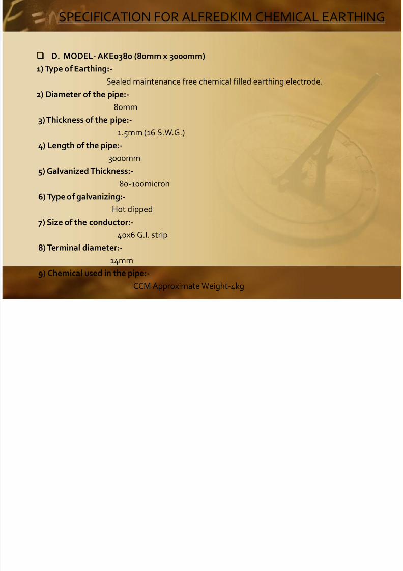
8/3/2019 Chemical Earthing 2011 FAQ
http://slidepdf.com/reader/full/chemical-earthing-2011-faq 86/99
D. MODEL- AKE0380 (80mm x 3000mm)
1) Type of Earthing:-
Sealed maintenance free chemical filled earthing electrode.
2) Diameter of the pipe:-
80mm
3) Thickness of the pipe:-
1.5mm (16 S.W.G.)
4) Length of the pipe:- 3000mm
5) Galvanized Thickness:-
80-100micron
6) Type of galvanizing:-
Hot dipped
7) Size of the conductor:-
40x6 G.I. strip
8) Terminal diameter:-
14mm
9) Chemical used in the pipe:-
CCM Approximate Weight-4kg
SPECIFICATION FOR ALFREDKIM CHEMICAL EARTHING

8/3/2019 Chemical Earthing 2011 FAQ
http://slidepdf.com/reader/full/chemical-earthing-2011-faq 87/99
D. MODEL- AKE0380 (80mm x 3000mm)
10) GBFC (Ground Back Fill Compound) :-
I) Minimum 60 kg it is soil enrichment chemical mainly consisting Aluminum
Silicate.
II) It absorbs moisture but doesn’t get dissolved in water.
III) It can absorb water 13 times of its weight.
IV) The top & bottom of the pipe is sealed permanently.
11) Earth fault capacity:-
1000KVA
12) Surface Area:-
753600mm
13) Brand:-
Alfredkim
14) Manufactures:-
ALFREDKIM SYSTEMS & SOLUTIONS PRIVATE LIMITED
14/3, Bolton Compound, Mathura Road, Faridabad-121003,
Haryana (India)
www.alfredkim.net
SCOPE OF WORK:-
8/3/2019 Chemical Earthing 2011 FAQ
http://slidepdf.com/reader/full/chemical-earthing-2011-faq 88/99
Our scope of work includes mainly the installing the electrode and making anearth station at the
point of location identified by DCW.The work related to the installing of the electrode including making a bore in the
ground is part of
the installation of the electrode. The additional work relating to the civil,mechanical or electrical
work not directly pertaining to the installation of electrode will be out of ourscope of work.
If such work is carried out at your request will subject to mutual consent at aprice quoted by the
manufacturers and accepted by the department.
SCOPE OF WORK:-
8/3/2019 Chemical Earthing 2011 FAQ
http://slidepdf.com/reader/full/chemical-earthing-2011-faq 89/99
The connecting strip from the earth station i.e. the electrode to the point of equipment which will
be connected will be charged to you at the rate of per meter length and will bepart of contract of
supply, installation of the electrode. The department will have to provide us atthe enquiry stage
the approximate running length of the strip for giving the quote but actual
payment will be madeby the department by the measurement of the length.
Procedure of laying the connecting strip from earth station to equipmentUNDER THE GROUND:-
The G.I. strip of appropriate dimension say e.g. 65mmx8mm shall be laid into atrench on the
ground.
The trench will be 250mm deep and about 20mm wide where in the G.I strip willbe laid into embedded with the GBFC compound in two or more layers below
and the above the strip.
SCOPE OF WORK:-

8/3/2019 Chemical Earthing 2011 FAQ
http://slidepdf.com/reader/full/chemical-earthing-2011-faq 90/99
On the surface of wall or else where:-
The G.I. strip will be carried on the surface of wall with a provision of cleat to provide the
gap between the wall and strip.The laying of the strip includes the labour charges for digging and refilling the trench @
Rs. 100/-
per meter length. For laying the strip on the wall or similar surface @ Rs. 75/- per meter
which includes supply of cleat and fixing hardware like screws, washers etc.
Cost of the Chemical:-
It will be about 20 kilos per meter length. The chemical will be filled in the trench in twolayers in form of slurry under neath the strip and above the strip. The chemical will beRs. 30/- per kilos and therefore the cost will be Rs. 600/-per mtr.
Earth Pit Cover:-
The earthing electrode will be supplied with Cast Iron (C.I.) cover (similar to manhole
cover) this will include the masonry work related to the small brick work which will be
carried out by us. The Cast Iron cover will be supplied @ Rs. 550/-.Thanking You,
Alfred Kim Systems Pvt. Ltd.
Who Are Our Important Customer?

8/3/2019 Chemical Earthing 2011 FAQ
http://slidepdf.com/reader/full/chemical-earthing-2011-faq 91/99
Faridabad:-
1. Pyramid Control System pvt Ltd
14/4, Mathura Road, Faridabad
2. Havells India Pvt Ltd
14/3, Mathura road, Faridabad
3. Laroiya Medicare Centre Pvt Ltd
997/7C, Faridabad
4. Siya Ram Engineers
Shed No. 150 Type-A, HSIIDC Sec-31, Faridabad
5. Joneja Bright Steel Pvt Ltd
Plot No.239&244, sec-24, Faridabad
6. Vijay Engineering & Metal Works
Plot no.165/66, Sec-24, Faridabad
7. Swastika Automatics
S.G.M Nagar, Faridabad
8. Asha Telecom Pvt ltd
17/3, Mathura Road, Faridabad 9. Prime Electronics
14/3, Mathura Road, Faridabad
10. Fine Turn 240, Sector -24, Faridabad
11. S. R. Engineers A-150 Sector-31, Faridabad 12. Saraswati Sishu School
Tegoan, Ballabgarh, Faridabad 13. Dev tech Printers
14/3 Mathura Road, Faridabad 14. Iskan India,
Gandhi Colony, Railway Road, Faridabad
15. SPCP Industries, A-50, 16/5, Mathura Road, Kakhanabag, Faridabad
16. Malhotra Shaving Products Pvt Ltd Factory-23/7, Sec-59, Ballabgarh, Faridabad-121004
17. Lakhani Vardan Group (LVG) Plot No.131, Sec-24, Ballabgarh, Faridabad
Who Are Our Important Customer?
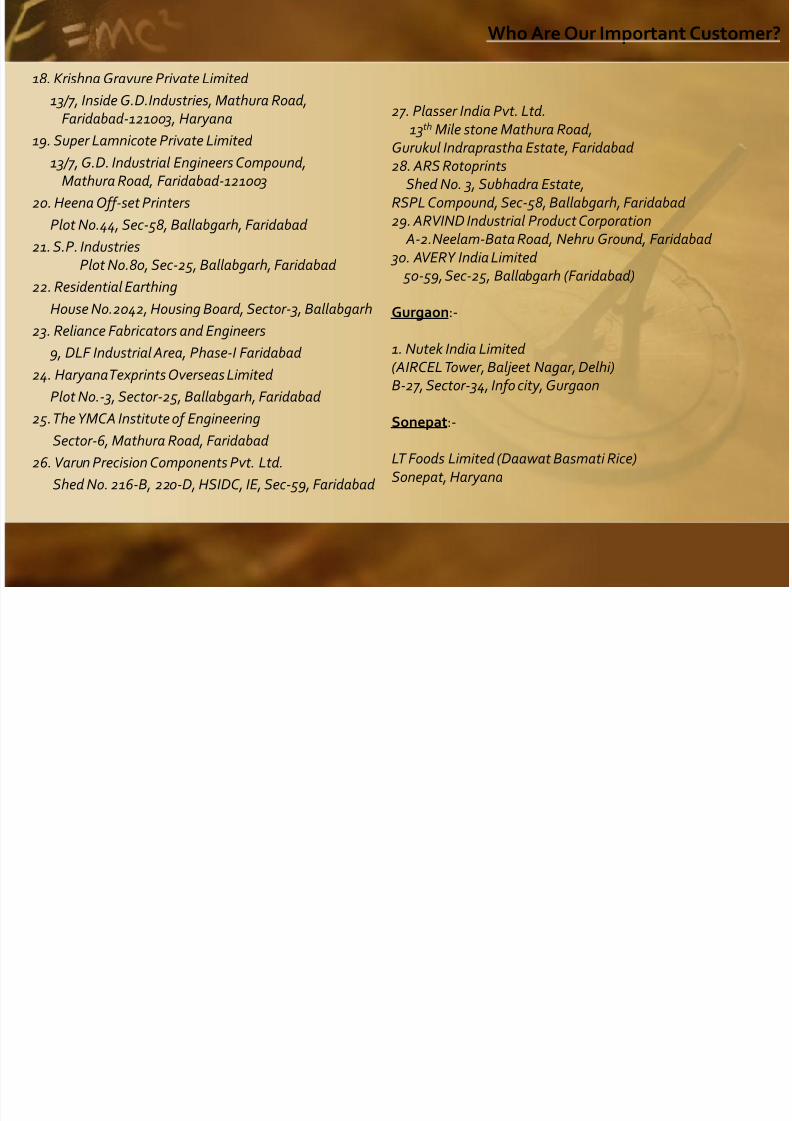
8/3/2019 Chemical Earthing 2011 FAQ
http://slidepdf.com/reader/full/chemical-earthing-2011-faq 92/99
18. Krishna Gravure Private Limited
13/7, Inside G.D.Industries, Mathura Road,Faridabad-121003, Haryana
19. Super Lamnicote Private Limited
13/7, G.D. Industrial Engineers Compound,Mathura Road, Faridabad-121003
20. Heena Off-set Printers
Plot No.44, Sec-58, Ballabgarh, Faridabad
21. S.P. IndustriesPlot No.80, Sec-25, Ballabgarh, Faridabad
22. Residential Earthing House No.2042, Housing Board, Sector-3, Ballabgarh
23. Reliance Fabricators and Engineers
9, DLF Industrial Area, Phase-I Faridabad
24. Haryana Texprints Overseas Limited
Plot No.-3, Sector-25, Ballabgarh, Faridabad
25. The YMCA Institute of Engineering
Sector-6, Mathura Road, Faridabad
26. Varun Precision Components Pvt. Ltd.
Shed No. 216-B, 220-D, HSIDC, IE, Sec-59, Faridabad
27. Plasser India Pvt. Ltd. 13th Mile stone Mathura Road,
Gurukul Indraprastha Estate, Faridabad 28. ARS Rotoprints Shed No. 3, Subhadra Estate,
RSPL Compound, Sec-58, Ballabgarh, Faridabad 29. ARVIND Industrial Product Corporation
A-2.Neelam-Bata Road, Nehru Ground, Faridabad 30. AVERY India Limited
50-59, Sec-25, Ballabgarh (Faridabad)
Gurgaon:-
1. Nutek India Limited (AIRCEL Tower, Baljeet Nagar, Delhi) B-27, Sector-34, Info city, Gurgaon
Sonepat:-
LT Foods Limited (Daawat Basmati Rice) Sonepat, Haryana
Who Are Our Important Customer?

8/3/2019 Chemical Earthing 2011 FAQ
http://slidepdf.com/reader/full/chemical-earthing-2011-faq 93/99
DELHI
1. Tri Square Switchgears Private Limited
A-8, DSIDC Sheds, Narera, Delhi
2. Control & Switchgear Private Limited (For Installation at South Block)
222, Okhla Industrial area, Phase-III, NewDelhi-110020
3. Mother dairy Plant
Patparganj, Delhi
4. ADEP BIO-TEC Industry Limited
29/15, Village-Pindwala, Khurd, Najafgarh Road,
New Delhi 5. Residential Earthing
House No.1, Mini Farm, Vasant Kunj, New Delhi
UTTAR PARDESH
Noida:-
1. Castrol Zone A-14 Sector 58, Noida
2. Keizer Pvt ltd
D-328, Sector 63, Noida
3. U Flex Industries Ltd Plot No.-1 sector 60, Noida
4. Daltronics India Ltd. A-88 Sec 57, Noida
5. Daltronics India Ltd. E-3, Sec-59, Noida
6. Supertech Diesel Power Engineers C-89, Sector-44, Noida-201301
Ghaziabad:- 1. SiddhoMal paper Conversion Pvt. Ltd.
20 Loni roads Industrial Area, Mohan Nagar, Ghaziabad 2. Spark Engineering P Ltd.
40/1, Site IV, Sahibabad industrial Area, Ghaziabad 3. Castrol Zone
Site IV, Sahibabad 4. Coca Cola Factory Site-IV, Sahibabad industrial Area, Ghaziabad RAJASTHAN1. Daikin Air-Conditioning (India) Pvt, Ltd
Sp-2/12, To Sp-2/15 & Sp-2/24 to Sp-2/27,RIICO New Industrial Complex (Nimrana) DDistt- Alwar, Rajasthan
2. Deepak Vegpro Pvt. Ltd. Old Industrial Area, Itarana Road, Alwar, Rajasthan

8/3/2019 Chemical Earthing 2011 FAQ
http://slidepdf.com/reader/full/chemical-earthing-2011-faq 94/99
LIGHTER MOOD - VACANCY FOR AN ELECTRICIAN IN INDIA!
Immediate requirement, No previous experience
necessary.
All gear supplied, pliers and screwdriver available at depot.
No overtime restrictions,
Salary: negotiable
Working hours: till the job is done
Essential requirement - fault finding skills!
IMPORTANT: To get an idea of your first assignment

8/3/2019 Chemical Earthing 2011 FAQ
http://slidepdf.com/reader/full/chemical-earthing-2011-faq 95/99
EAST DELHI

8/3/2019 Chemical Earthing 2011 FAQ
http://slidepdf.com/reader/full/chemical-earthing-2011-faq 96/99
East Delhi

8/3/2019 Chemical Earthing 2011 FAQ
http://slidepdf.com/reader/full/chemical-earthing-2011-faq 97/99
Chawri Bazaar

8/3/2019 Chemical Earthing 2011 FAQ
http://slidepdf.com/reader/full/chemical-earthing-2011-faq 98/99
Chandni Chowk
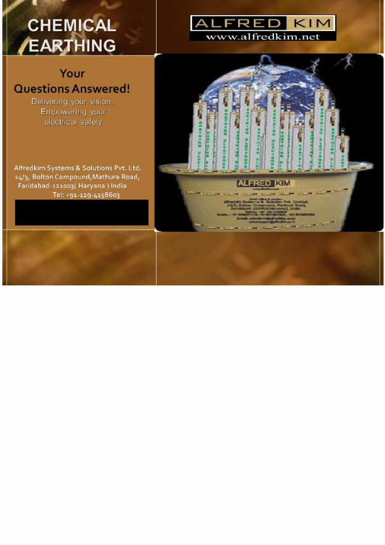
8/3/2019 Chemical Earthing 2011 FAQ
http://slidepdf.com/reader/full/chemical-earthing-2011-faq 99/99
+91 8800797774, [email protected]