Embed Size (px)
Citation preview
Chemical Engineering Science 94 (2013) 108–119
Contents lists available at SciVerse ScienceDirect
Chemical Engineering Science
0009-25
http://d
n Corr
E-m
journal homepage: www.elsevier.com/locate/ces
Long term stability of PTFE and PVDF membrane contactors in theapplication of propylene/propane separation using AgNO3 solution
Rami Faiz a, Marcos Fallanza b, Somnuk Boributh c, Ratana Jiraratananon c,Inmaculada Ortiz b, K. Li a,n
a Department of Chemical Engineering, Imperial College London, South Kensington Campus, London SW7 2AZ, UKb Advanced Separation Processes Research Group, Department of Chemical Engineering and Inorganic Chemistry, University of Cantabria, Spainc Department of Chemical Engineering, King’s Mongkut University of Technology, Thonburi, Bangkok 10140, Thailand
H I G H L I G H T S
c PTFE and PVDF membranes are investigated for propylene/propane separation.c PVDF has undergone some considerable accumulation of silver deposits.c Although silver deposition still occurred on the PTFE membranes, it’s impact was not as severe as that of PVDF.c Long term analysis revealed that the performance of PTFE remained invariable.
a r t i c l e i n f o
Article history:
Received 4 January 2013
Received in revised form
18 February 2013
Accepted 20 February 2013Available online 28 February 2013
Keywords:
Membranes
Mass transfer
Separations
Absorption
PTFE/PVDF
Propylene/propane
09/$ - see front matter & 2013 Elsevier Ltd. A
x.doi.org/10.1016/j.ces.2013.02.048
esponding author. Tel.: þ44 207 5945676; fa
ail address: [email protected] (K. Li).
a b s t r a c t
This study reports the long term stability of highly hydrophobic polymeric membranes such as PTFE
and PVDF in the application of membrane contactors for propylene/propane separation using silver
nitrate as carrier. Initial comparisons revealed that the PTFE membrane module was able to operate
under non-wetting conditions where the separation performance was the highest. Conversely, the PVDF
membrane module showed a much lower performance under the same operating conditions due to
partial wetting of the pores. Moreover, a long-term stability analysis was also carried out for a period of
2 months to check whether any additional deterioration in the performance of these membranes was
possible. Interestingly, the performance of PTFE did not change with time, whereas the PVDF
membranes exhibited a linear decrease in the overall mass transfer coefficient along the investigation
period, owing to an increase in the wetted pore fraction of the membrane. Characterization of these
hollow fibres after 2 months contact with the solvent revealed that PVDF have undergone some
considerable accumulation of silver deposits that induced the formation of voids and defects on the
membrane surface. The tendency for PVDF to wet with the solvent and its incompatibility with Ago
particles resulted in significant variations to the membrane properties which makes PVDF a non-
suitable membrane material for this application. On the other hand, although silver deposition still
occurred on the PTFE membranes, its impact was not as severe as that of PVDF to further cause any
structural damage. PTFE membranes seem to be a better option for the application of olefin/paraffin
separation using silver carriers as no deterioration in the long term performance was observed, at least
for an operating period of 2 months as demonstrated in this article.
& 2013 Elsevier Ltd. All rights reserved.
1. Introduction
Light hydrocarbons such as ethylene and propylene are vital tothe petrochemical industries because they are utilized as rawmaterials for many essential chemicals and products used in dailyconsumptions. For nearly seven decades, separation of olefins
ll rights reserved.
x: þ44 207 5945629.
from refinery catalytic cracker streams has been mainly per-formed by cryogenic distillation techniques which are classifiedas one of the most energy-intensive processes in the oil and gasindustry (Bryan, 2004). In the past few decades, many researchershave paid attention to develop new alternatives to solve theeconomical and environmental problems associated with thesetraditional technologies (Bryan, 2004; Eldridge, 1993; Faiz and Li,2012a, 2012b). Among a number of alternatives, the application ofreactive absorption of olefins from olefin/paraffin gas mixturesusing transition metal salt solutions as the absorbent solvents has
R. Faiz et al. / Chemical Engineering Science 94 (2013) 108–119 109
been given high considerations (Safarik and Eldridge, 1998).The separation process is based on the ability of olefins to formreversible organometallic complexes with some transition metalcations such as Agþ ions via the p-bound formation mechanism(Cho et al., 1995; Quinn, 1971; Nymeijer et al., 2004c; Reine andEldridge, 2005). The advantage of this chemical complexationrelies in the fact that these bonds are stronger than those formedby Van der Waals forces alone, but at the same time are still weakenough to be broken by using simple engineering operations suchas raising the temperature or decreasing the pressure (King, 1987;Ortiz et al., 2008).
The use of hollow fibre membrane contactors (HFMCs) havebeen considered by many researchers as a new means for gas/vapour separation applications while having many advantagesover conventional direct gas–liquid techniques such as spraytowers and packed/tray columns (DeMontigny et al., 2005;Gabelman and Hwang, 1999). In this process, two phases (usuallya gas phase and an absorbent solvent) come into direct contact forthe purpose of mass transfer without the dispersion of one phaseinto the other due to the presence of the membrane. In thismanner, operating drawbacks occurring in conventional absorptionprocesses are not possible. In fact, independent gas and liquid flowcontrol in HFMCs promotes easy operation without foam formationor flooding occurring, which in return makes the scale up of theprocess straight forward. In addition, HFMCs offers high masstransfer surface area per unit volume of the contactor, and there-fore much more compact units are also possible (Li and Cheng,2005). However, some of the major shortcomings associated withmembrane contactors, is the issue of membrane wetting caused bythe continuous contact with the solvent, which causes a substantialdecline in the overall mass transfer rate as described by variousauthors (Atchariyawut et al., 2007; Rangwala, 1996; Wang et al.,2004, 2005). However, the long term impact of this wettingphenomenon on the membrane properties is greater than justdeteriorating and decreasing the efficiency and performance of theprocess.
For instance, Wang et al. (2004) discussed the exposure ofmicroporous polypropylene (PP) membranes to Diethanolamine(DEA) and its influence on the membrane structure. It was foundthat the hollow fibres suffered from drastic changes in terms ofpore structure and surface roughness when exposed to DEAwithout CO2, suggesting that a chemical reaction was possiblebetween the amine solution and the membrane material.Recently, Lv et al. (2010) investigated the impact of Monoetha-nolamine (MEA), Methyldiethanolamine (MDEA), and water on PPhollow fibres immersed in the solvents up to 3 months period.The analysis confirmed that the absorbent molecules diffused intothe PP membranes during immersion, resulting in membraneswelling. The interaction between the membrane and the absor-bents further altered the surface properties of the membranereducing its hydrophobicity and contact angle with the solvents.The average equivalent pore diameter was also reported toincrease with longer immersion times which led to easier pene-tration of the solvent into the pores (Lv et al., 2010). However,other studies suggest that not only amine solutions could wet themembrane and cause further modifications to the membraneproperties, but it could even occurs with simple physical solventssuch as water. Barbe et al. (2000) observed changes in themorphology of polypropylene membranes after being exposedto water for 72 h, but attributed this variation to the non-wettingintrusion of the water meniscus into some pores which acted toenlarge some of the pore entrances.
On the other hand, olefin/paraffin separation studies in mem-brane contactors are usually carried out with the use of silver saltssolutions which are considered less corrosive, hazardous andflammable than all amine-based solvents. Consequently, one would
think that it should have a very minor impact on the membraneproperties and thus, extends its life time. However, among themany reports in the literature dealing with this subject (Fallanza etal., 2011a, 2011b; Nymeijer et al., 2004a, 2004b, 2004c; Ortiz et al.,2010) there are only very few attempts that have been focusing onmoving towards the large scale application of HFMCs for olefin/paraffin separation (Kwasniewski et al., 1999). This suggests thatthis process still suffers from several inherent challenges that mustbe overcome first, before shifting into larger scale applications. Asshown by Kwasniewski et al. (1999), BP Amoco studied themembrane-based contactors for olefin separation extensively usingPP hollow fibre membranes and silver nitrate as a carrier up to apilot plant stage. It was found that although the process wastechnically sound, the operating cost of the process was tooexpensive mainly due to the short life span of the membranescaused by the limited thermal and chemical stability whenextensively used with silver nitrate, even though the possibilityof other carriers such as molybdenum sulphides were also explored(Koval et al., 1995).
It is evident that most of the published work in the literaturethat focuses on membrane contactors for gas/vapour separationapplications considers polypropylene membranes due to its cheapcost and availability in various commercial geometries. However,its poor chemical compatibility and resistance against most sol-vents such as amine solvents and silver-based solutions is still amajor concern. Nowadays, polyvinylidene fluoride (PVDF) andpolytetrafluoroethylene (PTFE) hollow fibres have been emergingas strong candidates for membrane contactors due to their highhydrophobicity and chemical resistance against most solvents;however, they are yet to be utilized extensively for olefin/paraffinseparation (Rajabzadeh et al., 2010) whereas CO2 capture havebeen examined more intensively (Rajabzadeh et al., 2009; Ghasemet al., 2011, 2012). Nevertheless, most of the stability studiesreported in the literature considered a relatively short operatingperiods which are usually in the range of few days (Rajabzadehet al., 2010) to several weeks (Atchariyawut et al., 2007). However,implementation of such a process in a larger scale requiresextended stability studies where more insight on the long terminteractions between the membrane and the solvent could beestablished.
This study aims at investigating the long term stability ofhighly hydrophobic polymeric hollow fibres such as PVDF andPTFE in the application of membrane contactors for propylene/propane separation while utilizing AgNO3 as the absorbentsolvent. Initial characterizations of these hollow fibres were alsocarried out to determine the membrane properties prior totesting. In addition, the long term performance using thesemembrane modules was investigated for a continuous period of2 months. The impact and severity of the extensive contact ofsilver nitrate on the membrane properties and its consequenceeffect on the separation performance is demonstrated and dis-cussed in details.
2. Theory
For gas–liquid membrane contactors, the operations can beclassified into three operating modes, non-wetted (dry) mode,partially wetted mode, and completely wetted mode. Althoughthe operation in dry-mode is usually preferred, the operation in apartially wetted mode is commonly observed since it may not bepossible to maintain a non-wetted mode over a long termoperation (Gabelman and Hwang, 1999). The resistance-in-series approach and the resistance-in-series model for partiallywetted hollow fibre module with liquid flowing in the lumen side,counter-currently to the gas flowing in the shell side of the hollow
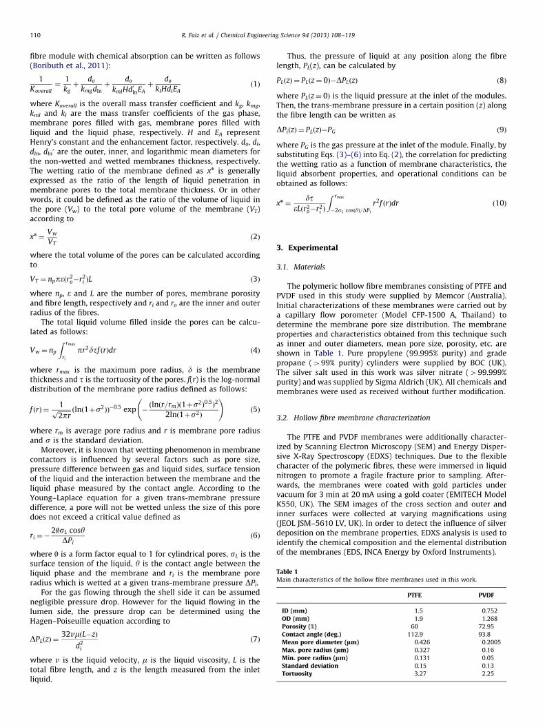
Table 1Main characteristics of the hollow fibre membranes used in this work.
PTFE PVDF
ID (mm) 1.5 0.752
OD (mm) 1.9 1.268
Porosity (%) 60 72.95
Contact angle (deg.) 112.9 93.8
Mean pore diameter (lm) 0.426 0.2005
Max. pore radius (lm) 0.327 0.16
Min. pore radius (lm) 0.131 0.05
Standard deviation 0.15 0.13
Tortuosity 3.27 2.25
R. Faiz et al. / Chemical Engineering Science 94 (2013) 108–119110
fibre module with chemical absorption can be written as follows(Boributh et al., 2011):
1
Koverall¼
1
kgþ
do
kmgdlnþ
do
kmlHd0lnEA
þdo
klHdiEAð1Þ
where Koverall is the overall mass transfer coefficient and kg, kmg,kml and kl are the mass transfer coefficients of the gas phase,membrane pores filled with gas, membrane pores filled withliquid and the liquid phase, respectively. H and EA representHenry’s constant and the enhancement factor, respectively. do, di,dln, dln
0 are the outer, inner, and logarithmic mean diameters forthe non-wetted and wetted membranes thickness, respectively.The wetting ratio of the membrane defined as xn is generallyexpressed as the ratio of the length of liquid penetration inmembrane pores to the total membrane thickness. Or in otherwords, it could be defined as the ratio of the volume of liquid inthe pore (Vw) to the total pore volume of the membrane (VT)according to
xn ¼Vw
VTð2Þ
where the total volume of the pores can be calculated accordingto
VT ¼ nppeðr2o�r2
i ÞL ð3Þ
where np, e and L are the number of pores, membrane porosityand fibre length, respectively and ri and ro are the inner and outerradius of the fibres.
The total liquid volume filled inside the pores can be calcu-lated as follows:
Vw ¼ np
Z rmax
ri
pr2dtf ðrÞdr ð4Þ
where rmax is the maximum pore radius, d is the membranethickness and t is the tortuosity of the pores. f(r) is the log-normaldistribution of the membrane pore radius defined as follows:
f ðrÞ ¼1ffiffiffiffiffiffiffiffi2prp ðlnð1þs2ÞÞ
�0:5 exp �ðlnðr=rmÞð1þs2Þ
0:5Þ2
2lnð1þs2Þ
!ð5Þ
where rm is average pore radius and r is membrane pore radiusand s is the standard deviation.
Moreover, it is known that wetting phenomenon in membranecontactors is influenced by several factors such as pore size,pressure difference between gas and liquid sides, surface tensionof the liquid and the interaction between the membrane and theliquid phase measured by the contact angle. According to theYoung–Laplace equation for a given trans-membrane pressuredifference, a pore will not be wetted unless the size of this poredoes not exceed a critical value defined as
ri ¼�2|sL cosy
DPið6Þ
where | is a form factor equal to 1 for cylindrical pores, sL is thesurface tension of the liquid, y is the contact angle between theliquid phase and the membrane and ri is the membrane poreradius which is wetted at a given trans-membrane pressure DPi.
For the gas flowing through the shell side it can be assumednegligible pressure drop. However for the liquid flowing in thelumen side, the pressure drop can be determined using theHagen–Poiseuille equation according to
DPLðzÞ ¼32vmðL�zÞ
d2i
ð7Þ
where v is the liquid velocity, m is the liquid viscosity, L is thetotal fibre length, and z is the length measured from the inletliquid.
Thus, the pressure of liquid at any position along the fibrelength, PL(z), can be calculated by
PLðzÞ ¼ PLðz¼ 0Þ�DPLðzÞ ð8Þ
where PLðz¼ 0Þ is the liquid pressure at the inlet of the modules.Then, the trans-membrane pressure in a certain position (z) alongthe fibre length can be written as
DPiðzÞ ¼ PLðzÞ�PG ð9Þ
where PG is the gas pressure at the inlet of the module. Finally, bysubstituting Eqs. (3)–(6) into Eq. (2), the correlation for predictingthe wetting ratio as a function of membrane characteristics, theliquid absorbent properties, and operational conditions can beobtained as follows:
xn ¼dt
eLðr2o�r2
i Þ
Z rmax
�2sL cosðyÞ=DPi
r2f ðrÞdr ð10Þ
3. Experimental
3.1. Materials
The polymeric hollow fibre membranes consisting of PTFE andPVDF used in this study were supplied by Memcor (Australia).Initial characterizations of these membranes were carried out bya capillary flow porometer (Model CFP-1500 A, Thailand) todetermine the membrane pore size distribution. The membraneproperties and characteristics obtained from this technique suchas inner and outer diameters, mean pore size, porosity, etc. areshown in Table 1. Pure propylene (99.995% purity) and gradepropane (499% purity) cylinders were supplied by BOC (UK).The silver salt used in this work was silver nitrate (499.999%purity) and was supplied by Sigma Aldrich (UK). All chemicals andmembranes were used as received without further modification.
3.2. Hollow fibre membrane characterization
The PTFE and PVDF membranes were additionally character-ized by Scanning Electron Microscopy (SEM) and Energy Disper-sive X-Ray Spectroscopy (EDXS) techniques. Due to the flexiblecharacter of the polymeric fibres, these were immersed in liquidnitrogen to promote a fragile fracture prior to sampling. After-wards, the membranes were coated with gold particles undervacuum for 3 min at 20 mA using a gold coater (EMITECH ModelK550, UK). The SEM images of the cross section and outer andinner surfaces were collected at varying magnifications using(JEOL JSM–5610 LV, UK). In order to detect the influence of silverdeposition on the membrane properties, EDXS analysis is used toidentify the chemical composition and the elemental distributionof the membranes (EDS, INCA Energy by Oxford Instruments).
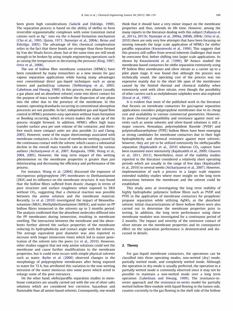
Fig. 1. Experimental setup for propylene/propane separation using hollow fibre membrane contactor.
R. Faiz et al. / Chemical Engineering Science 94 (2013) 108–119 111
3.3. Experimental set up for propane/propylene separation
The schematic diagram for propylene/propane separation using0.2 M silver nitrate solution as a carrier in the membrane contactorsexperiments is shown in Fig. 1. PTFE and PVDF membrane moduleswere prepared using 5 hollow fibres and was assembled in astainless steel tubes with an inner diameter of 8 mm and aneffective length of 22 cm. The feed gas mixture stream enteringthe membrane module was adjusted using mass flow controllers(Brooks Instrument MFC 5850) and flown through the shell side,while silver nitrate solution was flown through the lumen side ofthe membrane module using a gear pump (Cole-Parmer model75211-15) in a counter current arrangement. The operating gas andliquid pressures at the inlet and outlet of the membrane modulewere monitored using pressure gauges. The gas composition inthe outlet gas stream was analysed using a gas chromatograph(GC, Varian 3300, FID) equipped with an auto sampling gas valvesystem. The operating gas pressure was maintained at 1 bar whilethe operating liquid pressure was slightly higher at 1.2 bar to avoidgas bubbling. Since silver ions are very sensitive to light and air andcan be easily reduced to Ag1, it was chosen to re-circulate theaqueous solution in the experiment to minimize exposing thesolution to the surroundings. However, to make sure that solventsaturation did not occur very frequently, a 2.5 L solution of thedesired concentration was prepared and stored in a dark containerwhere it was used in the experimental runs. After each run,regeneration of the solvent was carried out by applying vacuum(o2 mbar) using an external vacuum pump (Telstar 2P3) connectedto the storage tank. Duration of the regeneration was allowed forseveral hours to assure compete decomplexation of propylene–Agþ
compounds, where the initial concentration of silver ions is com-pletely restored. Before a new experimental run, the concentrationof silver ions in the storage tank was checked and readjusted to thedesired concentration by using a simple titration method.
4. Results and discussion
4.1. Membrane characterization
The SEM images of the cross section, inner and outer surfacesof the PVDF and PTFE hollow fibres are shown in Fig. 2. It can benoticed that the thickness of the PTFE membrane is relatively
thinner than that of the PVDF. The inner and outer diameters ofthe PTFE hollow fibre were determined to be 1.5 and 1.9 mm,respectively, whereas for the PVDF membranes were 0.7 and1.268 mm, respectively, as shown in Table 1. Moreover, the outersurface of the PTFE membrane seems to be more porous than thatof PVDF as the entire outer surface is covered with uniformcylindrical pores as shown in Fig. 2A. However, the outer surfaceof the PVDF membrane contains only selective areas which areporous whereas the rest of the surface is dense as shown inFig. 2C. On the other hand, both the inner surfaces of PVDF andPTFE membranes seem to be quite porous. It should be noted thatthe porosity of the PTFE and PVDF membranes were determinedto be 0.60 and 0.72, respectively.
The chemical compositions of the hollow fibres prior tocontacting with silver nitrate were determined by EDXS means.It is known that for the PTFE polymers, one monomer unitcontains two carbon atoms attached to four fluorine atoms,whereas for the PVDF polymers, one monomer unit containstwo carbons attached to two fluorine and two hydrogen atoms.The elemental distribution of carbon, fluorine, and silver elementson the PTFE membrane surface was carried out by surfacemapping and demonstrated in Fig. 3. It can be seen that theelemental distribution of C and F atoms is well uniform on theentire membrane surface. However, it is very evident that theintensity of F is higher than that of C as anticipated for PTFEmembranes. Moreover, Fig. 3 shows that the elemental distribu-tion of Ag ions on the membrane surface prior to contacting isnegligible. The small detection of Ag ions on the membranesurface was confirmed to be due to the gold coating as Ag andAu had similar detection peaks. Nevertheless, the elementaldistribution of the contaminated hollow fibres after extensivecontact with silver nitrate would be able to distinguish betweenthe deposition of Ag particles and Au coating as demonstrated anddiscussed later in the article. In fact, the elemental distribution ofa new PTFE membrane was determined to be 58.27% (F) and41.73% (C). Similarly, the elemental distribution of F, C, and Agelements on the outer surface of the PVDF membrane was alsocarried out and shown in Fig. 4. It can be noticed that similar tothe PTFE membrane, the distribution of C and F atoms was welluniform and homogenous on the surface as well. However, theirintensity seems to be identical to each other, which is also in agood agreement with the actual composition of the polymer, i.e.50% carbon and 50% fluorine. Similar to Fig. 3, no Ag detection was
Fig. 2. The membrane structure of the polymeric membranes: (A) outer surface of PTFE, (B) inner surface of PTFE, (C) outer surface of PVDF, and (D) inner surface of PVDF.
R. Faiz et al. / Chemical Engineering Science 94 (2013) 108–119112
observed on the PVDF membrane prior to contacting with thesolvent. The chemical composition of the new PVDF membranedetermined by the EDXS analysis was given to be 52.46% and47.54% for F and C atoms, respectively.
4.2. Membranes comparison for propylene/propane separation
Gas absorption experiments using a 0.2 M AgNO3 with differentfeed gas compositions in the range 0–50% of propylene at atmo-spheric pressure and room temperature were carried out. Theoverall mass transfer coefficient in the system was experimentallydetermined, assuming negligible propane absorption following theprocedure described by Ortiz et al. (2010). These experiments werecarried out at liquid flow rates between 100 and 400 mL min�1
while the total gas flow rate was kept constant at 20 mL min�1.The absorbed propylene molar flux across the membrane as afunction of the propylene logarithmic mean molar fraction wasdetermined and shown in Fig. 5 for both PTFE and PVDF modules. Itis evident that a linear dependence of the molar flux as a functionof feed gas composition exists, as the absorbed propylene fluxincreases with increasing the propylene mole fraction in the gasmixture. The values of the overall mass transfer coefficients wereobtained from the slope of the lines as previously demonstrated(Luis et al., 2009; Ortiz et al., 2010). As for the PTFE module, it canbe seen that the overall mass transfer coefficient was increasedfrom 3.57�10�5 to 4.17�10�5 m s�1 as the liquid flow rate was
increased from 200 to 300 mL min�1. Further increase in the liquidflow rate to 400 mL min�1 also resulted in further enhancement ofthe overall mass transfer coefficient to 4.73�10�5 m s�1. How-ever, for the PVDF membrane module, a different behaviour wasobserved as shown in Fig. 5. Firstly, there was a slight increment inthe overall mass transfer coefficient from 2.72�10�5 to3.05�10�5 m s�1, as the liquid flow rate was increased from100 to 200 mL min�1, respectively. However, further increase inthe operating liquid flow rate to 250 mL min�1, resulted in afurther decline in the overall mass transfer coefficient as the valuedropped to 2.85�10�5 m s�1. This is a strong indication that thePVDF module was operated under wetting conditions for theinvestigated range of liquid flow rates as discussed andconfirmed below.
In order to compare the individual membrane mass transferresistances occurring in the membrane modules, the experimen-tal results were analysed using the Wilson-Plot method.The Wilson plot is a technique to experimentally determine themembrane mass transfer resistance in the gas–liquid membranecontacting process based upon the resistance-in-series model.A plot of 1/Koverall versus 1=va should result in a straight line.The value of the empirical parameter, a, is obtained for achievingthe best linear fit of the experimental data. In a membranecontactor system, if the resistance in the gas phase is muchsmaller than the total resistance occurring in the system, then theterm 1/kg defined in Eq. (1) becomes negligible and thus, the
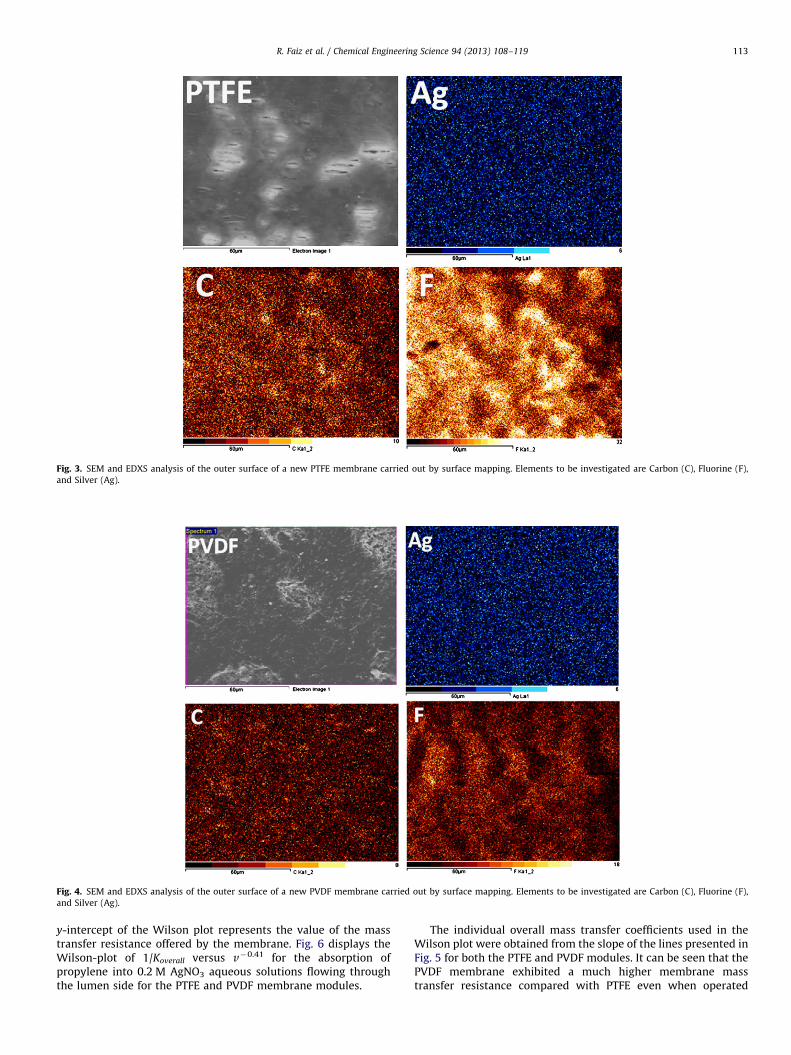
Fig. 3. SEM and EDXS analysis of the outer surface of a new PTFE membrane carried out by surface mapping. Elements to be investigated are Carbon (C), Fluorine (F),
and Silver (Ag).
Fig. 4. SEM and EDXS analysis of the outer surface of a new PVDF membrane carried out by surface mapping. Elements to be investigated are Carbon (C), Fluorine (F),
and Silver (Ag).
R. Faiz et al. / Chemical Engineering Science 94 (2013) 108–119 113
y-intercept of the Wilson plot represents the value of the masstransfer resistance offered by the membrane. Fig. 6 displays theWilson-plot of 1/Koverall versus v�0.41 for the absorption ofpropylene into 0.2 M AgNO3 aqueous solutions flowing throughthe lumen side for the PTFE and PVDF membrane modules.
The individual overall mass transfer coefficients used in theWilson plot were obtained from the slope of the lines presented inFig. 5 for both the PTFE and PVDF modules. It can be seen that thePVDF membrane exhibited a much higher membrane masstransfer resistance compared with PTFE even when operated
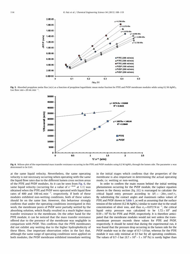
Fig. 5. Absorbed propylene molar flux (m/s) as a function of propylene logarithmic mean molar fraction for PTFE and PVDF membrane modules while using 0.2 M AgNO3.
Gas flow rate¼20 mL min�1.
Fig. 6. Wilson-plot of the experimental mass transfer resistance occurring in the PTFE and PVDF modules using 0.2 M AgNO3 through the lumen side. The parameter a was
determined to be 0.41.
R. Faiz et al. / Chemical Engineering Science 94 (2013) 108–119114
at the same liquid velocity. Nevertheless, the same operatingvelocity is not necessary occurring when operating with the samethe liquid flow rates due to the different lumen cross section areasof the PTFE and PVDF modules. As it can be seen from Fig. 6, thesame liquid velocity (occurring for a value of v�0.41 at 1.1) wasobtained when the PTFE and PVDF were operated with liquid flowrates of 400 and 100 mL min�1, respectively. If both of thesemodules exhibited non-wetting conditions, both of these valuesshould lie on the same line. However, this behaviour stronglyconfirms that under the operating conditions investigated in thiswork, the membrane pores of PVDF were partially wetted by theabsorbing solution, which finally resulted in a much higher masstransfer resistance in the membrane. On the other hand for thePTFE module, it can be noticed that the mass transfer resistanceoffered due to the presence of the membrane was negligible incomparison with PVDF. This confirms that the PTFE membranesdid not exhibit any wetting due to the higher hydrophobicity ofthese fibres. One important observation relies in the fact that,although the same range of operating conditions were applied onboth modules, the PVDF membrane exhibited immediate wetting
in the initial stages which confirms that the properties of themembrane is also important in determining the actual operatingmode, i.e. wetting or non-wetting.
In order to confirm the main reason behind the initial wettingphenomenon occurring for the PVDF module, the Laplace equationshown in the theory section (Eq. (6)) is rearranged to calculate thecritical liquid entry pressure according to DPi ¼�2|sL cosy=ri.By substituting the contact angles and maximum radius values ofPTFE and PVDF shown in Table 1, as well as assuming that the surfacetension of the solvent (0.2 M AgNO3) similar to water due to the smallconcentration of silver ions, and thus sL¼0.072 N m�1, the criticalliquid entry pressure was calculated to be 1.72�105 and0.59�105 Pa for PTFE and PVDF, respectively. It is therefore antici-pated that the membrane modules would not wet unless the trans-membrane pressure exceeds these values for PTFE and PVDF,respectively. It should be noted that during the experimental run, itwas found that the pressure drop occurring in the lumen side for thePVDF module was in the range of 0.7–1.0 bar, whereas for the PTFEmodule it was only minimal at 0.1 bar for all operating conditions.The values of 0.7–1 bar (0.7�105
�1�105 Pa) is surely higher than
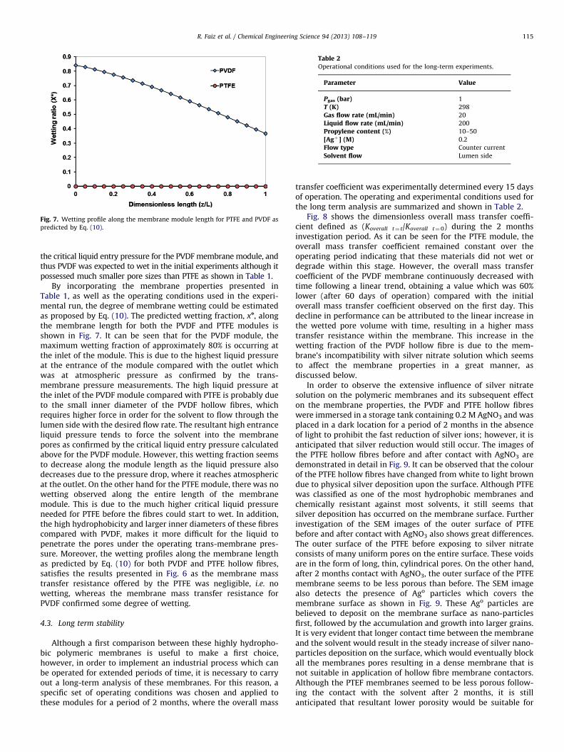
Fig. 7. Wetting profile along the membrane module length for PTFE and PVDF as
predicted by Eq. (10).
Table 2Operational conditions used for the long-term experiments.
Parameter Value
Pgas (bar) 1
T (K) 298
Gas flow rate (mL/min) 20
Liquid flow rate (mL/min) 200
Propylene content (%) 10–50
[Agþ] (M) 0.2
Flow type Counter current
Solvent flow Lumen side
R. Faiz et al. / Chemical Engineering Science 94 (2013) 108–119 115
the critical liquid entry pressure for the PVDF membrane module, andthus PVDF was expected to wet in the initial experiments although itpossessed much smaller pore sizes than PTFE as shown in Table 1.
By incorporating the membrane properties presented inTable 1, as well as the operating conditions used in the experi-mental run, the degree of membrane wetting could be estimatedas proposed by Eq. (10). The predicted wetting fraction, xn, alongthe membrane length for both the PVDF and PTFE modules isshown in Fig. 7. It can be seen that for the PVDF module, themaximum wetting fraction of approximately 80% is occurring atthe inlet of the module. This is due to the highest liquid pressureat the entrance of the module compared with the outlet whichwas at atmospheric pressure as confirmed by the trans-membrane pressure measurements. The high liquid pressure atthe inlet of the PVDF module compared with PTFE is probably dueto the small inner diameter of the PVDF hollow fibres, whichrequires higher force in order for the solvent to flow through thelumen side with the desired flow rate. The resultant high entranceliquid pressure tends to force the solvent into the membranepores as confirmed by the critical liquid entry pressure calculatedabove for the PVDF module. However, this wetting fraction seemsto decrease along the module length as the liquid pressure alsodecreases due to the pressure drop, where it reaches atmosphericat the outlet. On the other hand for the PTFE module, there was nowetting observed along the entire length of the membranemodule. This is due to the much higher critical liquid pressureneeded for PTFE before the fibres could start to wet. In addition,the high hydrophobicity and larger inner diameters of these fibrescompared with PVDF, makes it more difficult for the liquid topenetrate the pores under the operating trans-membrane pres-sure. Moreover, the wetting profiles along the membrane lengthas predicted by Eq. (10) for both PVDF and PTFE hollow fibres,satisfies the results presented in Fig. 6 as the membrane masstransfer resistance offered by the PTFE was negligible, i.e. nowetting, whereas the membrane mass transfer resistance forPVDF confirmed some degree of wetting.
4.3. Long term stability
Although a first comparison between these highly hydropho-bic polymeric membranes is useful to make a first choice,however, in order to implement an industrial process which canbe operated for extended periods of time, it is necessary to carryout a long-term analysis of these membranes. For this reason, aspecific set of operating conditions was chosen and applied tothese modules for a period of 2 months, where the overall mass
transfer coefficient was experimentally determined every 15 daysof operation. The operating and experimental conditions used forthe long term analysis are summarized and shown in Table 2.
Fig. 8 shows the dimensionless overall mass transfer coeffi-cient defined as (Koverall t¼ t/Koverall t¼0) during the 2 monthsinvestigation period. As it can be seen for the PTFE module, theoverall mass transfer coefficient remained constant over theoperating period indicating that these materials did not wet ordegrade within this stage. However, the overall mass transfercoefficient of the PVDF membrane continuously decreased withtime following a linear trend, obtaining a value which was 60%lower (after 60 days of operation) compared with the initialoverall mass transfer coefficient observed on the first day. Thisdecline in performance can be attributed to the linear increase inthe wetted pore volume with time, resulting in a higher masstransfer resistance within the membrane. This increase in thewetting fraction of the PVDF hollow fibre is due to the mem-brane’s incompatibility with silver nitrate solution which seemsto affect the membrane properties in a great manner, asdiscussed below.
In order to observe the extensive influence of silver nitratesolution on the polymeric membranes and its subsequent effecton the membrane properties, the PVDF and PTFE hollow fibreswere immersed in a storage tank containing 0.2 M AgNO3 and wasplaced in a dark location for a period of 2 months in the absenceof light to prohibit the fast reduction of silver ions; however, it isanticipated that silver reduction would still occur. The images ofthe PTFE hollow fibres before and after contact with AgNO3 aredemonstrated in detail in Fig. 9. It can be observed that the colourof the PTFE hollow fibres have changed from white to light browndue to physical silver deposition upon the surface. Although PTFEwas classified as one of the most hydrophobic membranes andchemically resistant against most solvents, it still seems thatsilver deposition has occurred on the membrane surface. Furtherinvestigation of the SEM images of the outer surface of PTFEbefore and after contact with AgNO3 also shows great differences.The outer surface of the PTFE before exposing to silver nitrateconsists of many uniform pores on the entire surface. These voidsare in the form of long, thin, cylindrical pores. On the other hand,after 2 months contact with AgNO3, the outer surface of the PTFEmembrane seems to be less porous than before. The SEM imagealso detects the presence of Ago particles which covers themembrane surface as shown in Fig. 9. These Ago particles arebelieved to deposit on the membrane surface as nano-particlesfirst, followed by the accumulation and growth into larger grains.It is very evident that longer contact time between the membraneand the solvent would result in the steady increase of silver nano-particles deposition on the surface, which would eventually blockall the membranes pores resulting in a dense membrane that isnot suitable in application of hollow fibre membrane contactors.Although the PTEF membranes seemed to be less porous follow-ing the contact with the solvent after 2 months, it is stillanticipated that resultant lower porosity would be suitable for
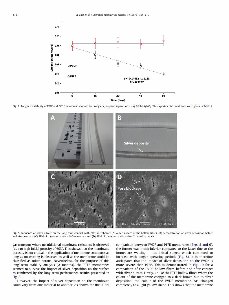
Fig. 8. Long term stability of PTFE and PVDF membrane module for propylene/propane separation using 0.2 M AgNO3. The experimental conditions were given in Table 2.
Fig. 9. Influence of silver nitrate on the long term contact with PTFE membrane: (A) outer surface of the hollow fibres, (B) demonstration of silver deposition before
and after contact, (C) SEM of the outer surface before contact and (D) SEM of the outer surface after 2 months contact.
R. Faiz et al. / Chemical Engineering Science 94 (2013) 108–119116
gas transport where no additional membrane resistance is observed(due to high initial porosity of 60%). This shows that the membraneporosity is not critical in the application of membrane contactors aslong as no wetting is observed as well as the membrane could beclassified as micro-porous. Nevertheless, for the purpose of thislong term stability analysis (2 months), the PTFE membranesseemed to survive the impact of silver deposition on the surfaceas confirmed by the long term performance results presented inFig. 8.
However, the impact of silver deposition on the membranecould vary from one material to another. As shown for the initial
comparison between PVDF and PTFE membranes (Figs. 5 and 6),the former was much inferior compared to the latter due to theimmediate wetting in the initial stages, which continued toincrease with longer operating periods (Fig. 8). It is thereforeanticipated that the impact of silver deposition on the PVDF ismore severe than PTFE. This is demonstrated in Fig. 10 for acomparison of the PVDF hollow fibres before and after contactwith silver nitrate. Firstly, unlike the PTFE hollow fibres where thecolour of the membrane changed to a dark brown due to silverdeposition, the colour of the PVDF membrane has changedcompletely to a light yellow shade. This shows that the membrane
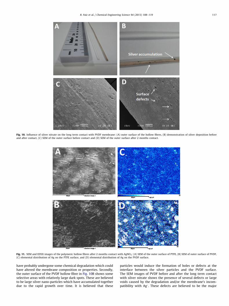
Fig. 10. Influence of silver nitrate on the long term contact with PVDF membrane: (A) outer surface of the hollow fibres, (B) demonstration of silver deposition before
and after contact, (C) SEM of the outer surface before contact and (D) SEM of the outer surface after 2 months contact.
Fig. 11. SEM and EDSX images of the polymeric hollow fibres after 2 months contact with AgNO3: (A) SEM of the outer surface of PTFE, (B) SEM of outer surface of PVDF,
(C) elemental distribution of Ag on the PTFE surface, and (D) elemental distribution of Ag on the PVDF surface.
R. Faiz et al. / Chemical Engineering Science 94 (2013) 108–119 117
have probably undergone some chemical degradation which couldhave altered the membrane composition or properties. Secondly,the outer surface of the PVDF hollow fibre in Fig. 10B shows someselective areas with relatively large dark spots. These are believedto be large silver nano-particles which have accumulated togetherdue to the rapid growth over time. It is believed that these
particles would induce the formation of holes or defects at theinterface between the silver particles and the PVDF surface.The SEM images of PVDF before and after the long term contactwith silver nitrate shows the presence of several defects or largevoids caused by the degradation and/or the membrane’s incom-patibility with Ag1. These defects are believed to be the major
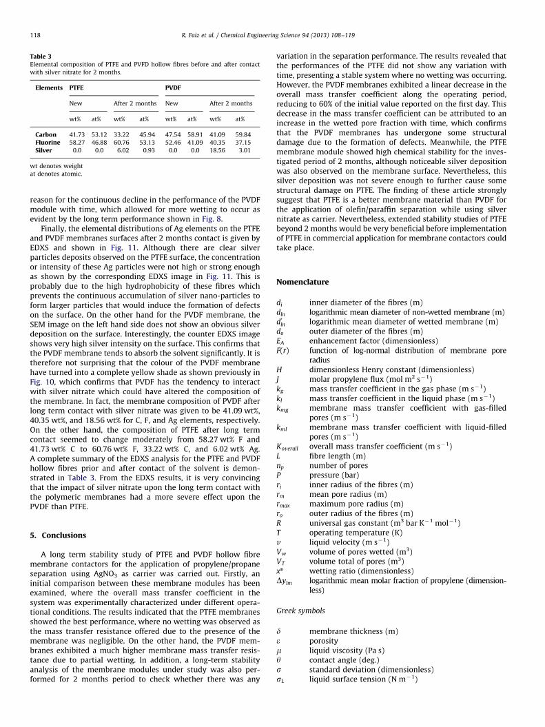
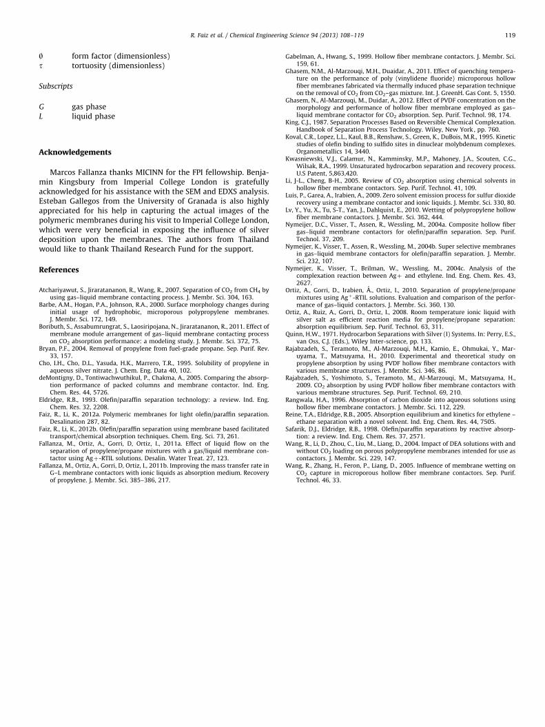
Table 3Elemental composition of PTFE and PVFD hollow fibres before and after contact
with silver nitrate for 2 months.
Elements PTFE PVDF
New After 2 months New After 2 months
wt% at% wt% at% wt% at% wt% at%
Carbon 41.73 53.12 33.22 45.94 47.54 58.91 41.09 59.84
Fluorine 58.27 46.88 60.76 53.13 52.46 41.09 40.35 37.15
Silver 0.0 0.0 6.02 0.93 0.0 0.0 18.56 3.01
wt denotes weight
at denotes atomic.
R. Faiz et al. / Chemical Engineering Science 94 (2013) 108–119118
reason for the continuous decline in the performance of the PVDFmodule with time, which allowed for more wetting to occur asevident by the long term performance shown in Fig. 8.
Finally, the elemental distributions of Ag elements on the PTFEand PVDF membranes surfaces after 2 months contact is given byEDXS and shown in Fig. 11. Although there are clear silverparticles deposits observed on the PTFE surface, the concentrationor intensity of these Ag particles were not high or strong enoughas shown by the corresponding EDXS image in Fig. 11. This isprobably due to the high hydrophobicity of these fibres whichprevents the continuous accumulation of silver nano-particles toform larger particles that would induce the formation of defectson the surface. On the other hand for the PVDF membrane, theSEM image on the left hand side does not show an obvious silverdeposition on the surface. Interestingly, the counter EDXS imageshows very high silver intensity on the surface. This confirms thatthe PVDF membrane tends to absorb the solvent significantly. It istherefore not surprising that the colour of the PVDF membranehave turned into a complete yellow shade as shown previously inFig. 10, which confirms that PVDF has the tendency to interactwith silver nitrate which could have altered the composition ofthe membrane. In fact, the membrane composition of PVDF afterlong term contact with silver nitrate was given to be 41.09 wt%,40.35 wt%, and 18.56 wt% for C, F, and Ag elements, respectively.On the other hand, the composition of PTFE after long termcontact seemed to change moderately from 58.27 wt% F and41.73 wt% C to 60.76 wt% F, 33.22 wt% C, and 6.02 wt% Ag.A complete summary of the EDXS analysis for the PTFE and PVDFhollow fibres prior and after contact of the solvent is demon-strated in Table 3. From the EDXS results, it is very convincingthat the impact of silver nitrate upon the long term contact withthe polymeric membranes had a more severe effect upon thePVDF than PTFE.
5. Conclusions
A long term stability study of PTFE and PVDF hollow fibremembrane contactors for the application of propylene/propaneseparation using AgNO3 as carrier was carried out. Firstly, aninitial comparison between these membrane modules has beenexamined, where the overall mass transfer coefficient in thesystem was experimentally characterized under different opera-tional conditions. The results indicated that the PTFE membranesshowed the best performance, where no wetting was observed asthe mass transfer resistance offered due to the presence of themembrane was negligible. On the other hand, the PVDF mem-branes exhibited a much higher membrane mass transfer resis-tance due to partial wetting. In addition, a long-term stabilityanalysis of the membrane modules under study was also per-formed for 2 months period to check whether there was any
variation in the separation performance. The results revealed thatthe performances of the PTFE did not show any variation withtime, presenting a stable system where no wetting was occurring.However, the PVDF membranes exhibited a linear decrease in theoverall mass transfer coefficient along the operating period,reducing to 60% of the initial value reported on the first day. Thisdecrease in the mass transfer coefficient can be attributed to anincrease in the wetted pore fraction with time, which confirmsthat the PVDF membranes has undergone some structuraldamage due to the formation of defects. Meanwhile, the PTFEmembrane module showed high chemical stability for the inves-tigated period of 2 months, although noticeable silver depositionwas also observed on the membrane surface. Nevertheless, thissilver deposition was not severe enough to further cause somestructural damage on PTFE. The finding of these article stronglysuggest that PTFE is a better membrane material than PVDF forthe application of olefin/paraffin separation while using silvernitrate as carrier. Nevertheless, extended stability studies of PTFEbeyond 2 months would be very beneficial before implementationof PTFE in commercial application for membrane contactors couldtake place.
Nomenclature
di inner diameter of the fibres (m)dln logarithmic mean diameter of non-wetted membrane (m)d0ln logarithmic mean diameter of wetted membrane (m)do outer diameter of the fibres (m)EA enhancement factor (dimensionless)F(r) function of log-normal distribution of membrane pore
radiusH dimensionless Henry constant (dimensionless)J molar propylene flux (mol m2 s�1)kg mass transfer coefficient in the gas phase (m s�1)kl mass transfer coefficient in the liquid phase (m s�1)kmg membrane mass transfer coefficient with gas-filled
pores (m s�1)kml membrane mass transfer coefficient with liquid-filled
pores (m s�1)Koverall overall mass transfer coefficient (m s�1)L fibre length (m)np number of poresP pressure (bar)ri inner radius of the fibres (m)rm mean pore radius (m)rmax maximum pore radius (m)ro outer radius of the fibres (m)R universal gas constant (m3 bar K�1 mol�1)T operating temperature (K)v liquid velocity (m s�1)Vw volume of pores wetted (m3)VT volume total of pores (m3)xn wetting ratio (dimensionless)Dylm logarithmic mean molar fraction of propylene (dimension-
less)
Greek symbols
d membrane thickness (m)e porositym liquid viscosity (Pa s)y contact angle (deg.)s standard deviation (dimensionless)sL liquid surface tension (N m�1)
R. Faiz et al. / Chemical Engineering Science 94 (2013) 108–119 119
| form factor (dimensionless)t tortuosity (dimensionless)
Subscripts
G gas phaseL liquid phase
Acknowledgements
Marcos Fallanza thanks MICINN for the FPI fellowship. Benja-min Kingsbury from Imperial College London is gratefullyacknowledged for his assistance with the SEM and EDXS analysis.Esteban Gallegos from the University of Granada is also highlyappreciated for his help in capturing the actual images of thepolymeric membranes during his visit to Imperial College London,which were very beneficial in exposing the influence of silverdeposition upon the membranes. The authors from Thailandwould like to thank Thailand Research Fund for the support.
References
Atchariyawut, S., Jiraratananon, R., Wang, R., 2007. Separation of CO2 from CH4 byusing gas–liquid membrane contacting process. J. Membr. Sci. 304, 163.
Barbe, A.M., Hogan, P.A., Johnson, R.A., 2000. Surface morphology changes duringinitial usage of hydrophobic, microporous polypropylene membranes.J. Membr. Sci. 172, 149.
Boributh, S., Assabumrungrat, S., Laosiripojana, N., Jiraratananon, R., 2011. Effect ofmembrane module arrangement of gas–liquid membrane contacting processon CO2 absorption performance: a modeling study. J. Membr. Sci. 372, 75.
Bryan, P.F., 2004. Removal of propylene from fuel-grade propane. Sep. Purif. Rev.33, 157.
Cho, I.H., Cho, D.L., Yasuda, H.K., Marrero, T.R., 1995. Solubility of propylene inaqueous silver nitrate. J. Chem. Eng. Data 40, 102.
deMontigny, D., Tontiwachwuthikul, P., Chakma, A., 2005. Comparing the absorp-tion performance of packed columns and membrane contactor. Ind. Eng.Chem. Res. 44, 5726.
Eldridge, R.B., 1993. Olefin/paraffin separation technology: a review. Ind. Eng.Chem. Res. 32, 2208.
Faiz, R., Li, K., 2012a. Polymeric membranes for light olefin/paraffin separation.Desalination 287, 82.
Faiz, R., Li, K., 2012b. Olefin/paraffin separation using membrane based facilitatedtransport/chemical absorption techniques. Chem. Eng. Sci. 73, 261.
Fallanza, M., Ortiz, A., Gorri, D, Ortiz, I., 2011a. Effect of liquid flow on theseparation of propylene/propane mixtures with a gas/liquid membrane con-tactor using Agþ-RTIL solutions. Desalin. Water Treat. 27, 123.
Fallanza, M., Ortiz, A., Gorri, D, Ortiz, I., 2011b. Improving the mass transfer rate inG–L membrane contactors with ionic liquids as absorption medium. Recoveryof propylene. J. Membr. Sci. 385–386, 217.
Gabelman, A., Hwang, S., 1999. Hollow fiber membrane contactors. J. Membr. Sci.159, 61.
Ghasem, N.M., Al-Marzouqi, M.H., Duaidar, A., 2011. Effect of quenching tempera-ture on the performance of poly (vinylidene fluoride) microporous hollowfiber membranes fabricated via thermally induced phase separation techniqueon the removal of CO2 from CO2–gas mixture. Int. J. GreenH. Gas Cont. 5, 1550.
Ghasem, N., Al-Marzouqi, M., Duidar, A., 2012. Effect of PVDF concentration on themorphology and performance of hollow fiber membrane employed as gas–liquid membrane contactor for CO2 absorption. Sep. Purif. Technol. 98, 174.
King, C.J., 1987. Separation Processes Based on Reversible Chemical Complexation.Handbook of Separation Process Technology. Wiley, New York , pp. 760.
Koval, C.R., Lopez, L.L., Kaul, B.B., Renshaw, S., Green, K., DuBois, M.R., 1995. Kineticstudies of olefin binding to sulfido sites in dinuclear molybdenum complexes.Organometallics 14, 3440.
Kwasniewski, V.J., Calamur, N., Kamminsky, M.P., Mahoney, J.A., Scouten, C.G.,Wilsak, R.A., 1999. Unsaturated hydrocarbon separation and recovery process.U.S Patent, 5,863,420.
Li, J-L., Cheng, B-H., 2005. Review of CO2 absorption using chemical solvents inhollow fiber membrane contactors. Sep. Purif. Technol. 41, 109.
Luis, P., Garea, A., Irabien, A., 2009. Zero solvent emission process for sulfur dioxiderecovery using a membrane contactor and ionic liquids. J. Membr. Sci. 330, 80.
Lv, Y., Yu, X., Tu, S-T., Yan, J., Dahlquist, E., 2010. Wetting of polypropylene hollowfiber membrane contactors. J. Membr. Sci. 362, 444.
Nymeijer, D.C., Visser, T., Assen, R., Wessling, M., 2004a. Composite hollow fibergas–liquid membrane contactors for olefin/paraffin separation. Sep. Purif.Technol. 37, 209.
Nymeijer, K., Visser, T., Assen, R., Wessling, M., 2004b. Super selective membranesin gas–liquid membrane contactors for olefin/paraffin separation. J. Membr.Sci. 232, 107.
Nymeijer, K., Visser, T., Brilman, W., Wessling, M., 2004c. Analysis of thecomplexation reaction between Agþ and ethylene. Ind. Eng. Chem. Res. 43,2627.
Ortiz, A., Gorri, D., Irabien, A., Ortiz, I., 2010. Separation of propylene/propanemixtures using Agþ-RTIL solutions. Evaluation and comparison of the perfor-mance of gas–liquid contactors. J. Membr. Sci. 360, 130.
Ortiz, A., Ruiz, A., Gorri, D., Ortiz, I., 2008. Room temperature ionic liquid withsilver salt as efficient reaction media for propylene/propane separation:absorption equilibrium. Sep. Purif. Technol. 63, 311.
Quinn, H.W., 1971. Hydrocarbon Separations with Silver (I) Systems. In: Perry, E.S.,van Oss, C.J. (Eds.), Wiley Inter-science, pp. 133.
Rajabzadeh, S., Teramoto, M., Al-Marzouqi, M.H., Kamio, E., Ohmukai, Y., Mar-uyama, T., Matsuyama, H., 2010. Experimental and theoretical study onpropylene absorption by using PVDF hollow fiber membrane contactors withvarious membrane structures. J. Membr. Sci. 346, 86.
Rajabzadeh, S., Yoshimoto, S., Teramoto, M., Al-Marzouqi, M., Matsuyama, H.,2009. CO2 absorption by using PVDF hollow fiber membrane contactors withvarious membrane structures. Sep. Purif. Technol. 69, 210.
Rangwala, H.A., 1996. Absorption of carbon dioxide into aqueous solutions usinghollow fiber membrane contactors. J. Membr. Sci. 112, 229.
Reine, T.A., Eldridge, R.B., 2005. Absorption equilibrium and kinetics for ethylene –ethane separation with a novel solvent. Ind. Eng. Chem. Res. 44, 7505.
Safarik, D.J., Eldridge, R.B., 1998. Olefin/paraffin separations by reactive absorp-tion: a review. Ind. Eng. Chem. Res. 37, 2571.
Wang, R., Li, D., Zhou, C., Liu, M., Liang, D., 2004. Impact of DEA solutions with andwithout CO2 loading on porous polypropylene membranes intended for use ascontactors. J. Membr. Sci. 229, 147.
Wang, R., Zhang, H., Feron, P., Liang, D., 2005. Influence of membrane wetting onCO2 capture in microporous hollow fiber membrane contactors. Sep. Purif.Technol. 46, 33.


![Corrosion Mechanism of Steels in MDEA Solution and ...Int. J. Electrochem. Sci., Vol. 12, 2017 5743 diethanolamine (DEA), and N-methyldiethanolamine (MDEA) [1]. Corrosion in alkanolamine](https://img.pdfslide.net/doc/110x75/60950527d7f23f2a03018b03/corrosion-mechanism-of-steels-in-mdea-solution-and-int-j-electrochem-sci.jpg)