Embed Size (px)
Citation preview

See discussions, stats, and author profiles for this publication at: https://www.researchgate.net/publication/42804843
Chemical Vapor Deposition of Carbon Nanotubes: A Review on Growth
Mechanism and Mass Production
Article in Journal of Nanoscience and Nanotechnology · June 2010
DOI: 10.1166/jnn.2010.2939 · Source: PubMed
CITATIONS
1,079READS
25,686
2 authors:
Some of the authors of this publication are also working on these related projects:
Battery View project
Nothing View project
Mukul Kumar
HEG Ltd. (Bhopal) India
58 PUBLICATIONS 3,166 CITATIONS
SEE PROFILE
Yoshinori Ando
Meijo University
199 PUBLICATIONS 10,131 CITATIONS
SEE PROFILE
All content following this page was uploaded by Yoshinori Ando on 16 May 2014.
The user has requested enhancement of the downloaded file.
REVIEW
Copyright © 2010 American Scientific Publishers
All rights reserved
Printed in the United States of America
Journal ofNanoscience and Nanotechnology
Vol. 10, 3739–3758, 2010
Chemical Vapor Deposition of Carbon Nanotubes:
A Review on Growth Mechanism and Mass Production
Mukul Kumar∗ and Yoshinori AndoDepartment of Materials Science and Engineering, Meijo University, Nagoya 468-8502, Japan
This review article deals with the growth mechanism and mass production of carbon nanotubes(CNTs) by chemical vapor deposition (CVD). Different aspects of CNT synthesis and growth mech-anism are reviewed in the light of latest progresses and understandings in the field. Materialsaspects such as the roles of hydrocarbon, catalyst and catalyst support are discussed. Many newcatalysts and new carbon sources are described. Growth-control aspects such as the effects oftemperature, vapor pressure and catalyst concentration on CNT diameter distribution and single- ormulti-wall formation are explained. Latest reports of metal-catalyst-free CNT growth are considered.The mass-production aspect is discussed from the perspective of a sustainable CNT technology.Existing problems and challenges of the process are addressed with future directions.
Keywords: Chemical Vapor Deposition (CVD), Carbon Nanotube (CNT), CNT GrowthMechanism, CNT Mass Production, CNT Industrial Production, CNT Precursor, CNTCatalyst, Catalyst-Free CNT Synthesis, Camphor.
CONTENTS
1. Introduction . . . . . . . . . . . . . . . . . . . . . . . . . . . . . . . . . . . . . . . . 3739
2. Chemical Vapor Deposition (CVD) . . . . . . . . . . . . . . . . . . . . . . 3740
2.1. History of CVD . . . . . . . . . . . . . . . . . . . . . . . . . . . . . . . . . 3740
2.2. Advantages of CVD . . . . . . . . . . . . . . . . . . . . . . . . . . . . . . 3741
3. CNT Synthesis . . . . . . . . . . . . . . . . . . . . . . . . . . . . . . . . . . . . . 3741
3.1. CNT Precursors . . . . . . . . . . . . . . . . . . . . . . . . . . . . . . . . . 3742
3.2. CNT Catalysts . . . . . . . . . . . . . . . . . . . . . . . . . . . . . . . . . . 3743
3.3. CNT Catalyst Supports . . . . . . . . . . . . . . . . . . . . . . . . . . . 3743
3.4. New (Uncommon) CNT Catalysts . . . . . . . . . . . . . . . . . . . 3744
3.5. Metal-Free CNT Growth . . . . . . . . . . . . . . . . . . . . . . . . . . 3744
3.6. New (Unconventional) CNT Precursors . . . . . . . . . . . . . . . 3745
4. CNT Growth Control . . . . . . . . . . . . . . . . . . . . . . . . . . . . . . . . . 3746
4.1. Effect of Catalyst Material and Concentration . . . . . . . . . . 3746
4.2. Effect of Temperature . . . . . . . . . . . . . . . . . . . . . . . . . . . . 3747
4.3. Effect of Vapor Pressure . . . . . . . . . . . . . . . . . . . . . . . . . . 3748
5. CNT Growth Mechanism Under Electron Microscopy . . . . . . . 3748
5.1. Physical State of the Catalyst . . . . . . . . . . . . . . . . . . . . . . . 3748
5.2. Mode of Carbon Diffusion . . . . . . . . . . . . . . . . . . . . . . . . . 3749
5.3. Chemical State of the Catalyst . . . . . . . . . . . . . . . . . . . . . . 3751
6. Mass Production of CNTs . . . . . . . . . . . . . . . . . . . . . . . . . . . . . 3751
6.1. Mass Production of CNTs from
Conventional Precursors . . . . . . . . . . . . . . . . . . . . . . . . . . . 3751
6.2. Mass Production of CNTs from Camphor . . . . . . . . . . . . . 3752
6.3. Camphor versus Conventional CNT Precursors . . . . . . . . . 3753
6.4. Environment-Friendliness of Camphor CVD . . . . . . . . . . . 3753
6.5. Industrial Production of CNTs from Camphor . . . . . . . . . . 3754
7. Existing Challenges and Future Directions . . . . . . . . . . . . . . . . 3754
∗Author to whom correspondence should be addressed.
8. Concluding Remarks . . . . . . . . . . . . . . . . . . . . . . . . . . . . . . . . . 3754
Acknowledgments . . . . . . . . . . . . . . . . . . . . . . . . . . . . . . . . . . . 3755
References and Notes . . . . . . . . . . . . . . . . . . . . . . . . . . . . . . . . 3755
1. INTRODUCTION
A carbon nanotube (CNT) is a tubular structure made
of carbon atoms, having diameter of nanometer order
but length in micrometers. Although this kind of struc-
tures was synthesized, studied and reported by several
researchers during 1952–1989,1–17 Iijima’s detailed anal-
ysis of helical arrangement of carbon atoms on seam-
less coaxial cylinders in 1991, proved to be a discovery
report.18 Since then, CNT has remained an exciting mate-
rial ever. Its so-called extraordinary properties: many-fold
stronger than steel, harder than diamond, electrical con-
ductivity higher than copper, thermal conductivity higher
than diamond, etc. set off a gold rush in academic and
industrial laboratories all over the world to find practical
uses of CNTs. This sprouted thousands of publications and
patents on innumerous potential applications of CNTs in
almost all the walks of life: media, entertainment, commu-
nication, transport, health and environment. The gold rush
turned into a stampede when NASA scientists and many
others predicted the possibility of making space elevators,
lighter and stronger aircrafts, collapsible and reshapable
cars, incredible new fabric, portable X-ray machines etc.
J. Nanosci. Nanotechnol. 2010, Vol. 10, No. 6 1533-4880/2010/10/3739/020 doi:10.1166/jnn.2010.2939 3739
REVIEW
Chemical Vapor Deposition of Carbon Nanotubes: A Review on Growth Mechanism and Mass Production Kumar and Ando
by using CNTs. Consequently, CNT has become a material
of common interest today; and society is eagerly waiting
for seeing the charisma of CNT in household products.
However, even after 18 years of continued efforts world-
wide, such products are still waitlisted.
The bottleneck is insufficient production and uncom-
petitive cost of CNTs with respect to the prevalent tech-
nology. Despite a huge progress in CNT research over
the years, we are still unable to produce CNTs of well-
defined properties in large quantities with a cost-effective
technique. The root of this problem is the lack of proper
understanding of the CNT growth mechanism. Till date
no definitive model could be robustly established for the
CNT growth. There are several issues in the growth mech-
anism that are yet to be clarified. Ironically, from the win-
dow of time machine, the CNT research today is ahead
of its time. We, the CNT researchers, know how to make
single-electron transistors from individual CNTs, but we
do not know how to make a CNT of the required structure.
Hence it is necessary to retrospect. The skytower of the
ambitious nanotechnology (in particular, CNT-based tech-
nology) cannot be erected without a firm foundation of the
growth-mechanism understanding.
Among several techniques of CNT synthesis available
today, chemical vapor deposition (CVD) is most popu-
lar and widely used because of its low set-up cost, high
production yield, and ease of scale-up. This review, there-
fore, deals with the growth mechanism and mass produc-
tion of CNTs by CVD. Beginning with a brief historical
account of CVD pertinent to CNT, we will cover differ-
ent aspects of CNT synthesis and growth mechanism in
Dr. Mukul Kumar received his B.Sc., M.Sc. and Ph.D. degrees in the Faculty of Sci-
ence (Physics) from Bihar University, India. During 1990–1996, he served as a Lecturer
of Physics in Jai Prakash University, India. In 1996, he joined Indian Institute of Tech-
nology, Bombay and worked for Indo-French, UNESCO, DMSRDE and CSIR Projects. In
Dec 2000, he joined Meijo University as a JSPS Fellow, and since Jan 2003, he has been a
senior scientist at the 21st Century Centre of Excellence there. Actively involved in research,
research guidance and education, Dr. Kumar’s areas of interest include electrochemistry
and photo-electrochemistry of group II–VI semiconductors, synthesis, characterization and
application of CNTs grown by CVD method, and electron field emission. He has published
48 research articles and 6 patents on syntheses of glassy carbon and carbon nanotubes, and
presented 80 papers at international conferences.
Professor Yoshinori Ando received his B.E., M.E. and D.E. degrees in the Faculty of
Engineering (Applied Physics) from Nagoya University, Japan. After five years post-doctoral
experience in Nagoya University, he moved to Meijo University as a Lecturer in Physics in
1974. He became Assistant Professor in 1977, and Professor in 1990. During 1987–1988, he
was a visiting research fellow at Bristol University, UK. During 2000–2004, he was the first
Head of the Department of Materials Science and Engineering in Meijo University. From
April 2009, he is the Dean of the Faculty of Science and Technology in Meijo University.
Professor Ando’s research areas include X-ray diffraction topography of distorted crystals,
electron microscopy of thin films and ultrafine particles of SiC, arc-discharge synthesis of
CNTs and their application to composite materials. He has published over 200 research
articles and a dozen of patents. He has presented over 100 papers at various conferences.
the light of latest progresses and understandings in the
field. On the materials aspect, the roles of hydrocarbon
and catalyst are discussed in detail. Many new catalysts
and new carbon sources are addressed. Among the new
CNT precursors, camphor is highlighted because of its
environment-friendliness and exceptionally-high efficiency
toward CNT production. On the growth-control aspect, the
effects of temperature, vapor pressure and catalyst concen-
tration on diameter distribution and single- or multi-wall
formation are discussed. The mass-production aspect is
covered stressing the need of a sustainable CNT technol-
ogy. Finally, we conclude with a brief mention of existing
challenges and future directions.
2. CHEMICAL VAPOR DEPOSITION (CVD)
Chemical vapor deposition (CVD) is the most popular
method of producing CNTs nowadays. In this process,
thermal decomposition of a hydrocarbon vapor is achieved
in the presence of a metal catalyst. Hence, it is also known
as thermal CVD or catalytic CVD (to distinguish it from
many other kinds of CVD used for various purposes).
2.1. History of CVD
The history of CVD for the synthesis of carbon filaments
dates back to nineteenth century. In 1890, French scientists
observed the formation of carbon filaments during exper-
iments involving the passage of cyanogens over red-hot
porcelain.19 By mid-twentieth century, CVD was an estab-
lished method for producing carbon microfibers utilizing
3740 J. Nanosci. Nanotechnol. 10, 3739–3758, 2010
REVIEW
Kumar and Ando Chemical Vapor Deposition of Carbon Nanotubes: A Review on Growth Mechanism and Mass Production
thermal decomposition of hydrocarbons in the presence of
metal catalysts. In 1952 Radushkevich and Lukyanovich
published a range of electron micrographs clearly exhibit-
ing tubular carbon filaments of 50–100 nm diameter grown
from thermal decomposition of carbon monoxide on iron
catalyst at 600 �C.1 They observed iron carbides encapsu-
lated in the filament tips; accordingly, they proposed that,
at first, carbon dissolution in iron resulted in the forma-
tion of iron carbide, and then, subsequent carbon depo-
sition over iron carbide led to the formation of graphene
layers. In the same year, another Russian group, Tes-
ner and Echeistova, also reported similar carbon threads
on lampblack particles exposed to methane, benzene or
cyclohexane atmospheres at temperatures above 977 �C.2
In 1953, Davis et al. published detailed electron micro-
graphs and XRD spectra of carbon nanofibers grown from
the reaction of CO and Fe2O4 at 450 �C in blast fur-
nace brickworks.3 They postulated that the catalyst for the
reaction, either iron or iron carbide, formed on the sur-
face of the iron oxide as a speck which in turn gave rise
to a thread of carbon. They suggested that, at the time
of carbon deposition, the catalyst particles were located
on the growing ends of the threads. The threads were
described as layered carbon, varying in thickness from
10 to 200 nm. Similar findings were reported by Hofer
et al. (1955),4 Walker (1959)5 and Baird et al. (1971).6�7 In
the 1970s extensive works were carried out independently
by Baker and Endo to synthesize and understand tubular
nanofibers of multi-layered carbon.8–12 Thus, today’s most-
popular CNT technique, the CVD, may probably be the
most-ancient technique of growing CNTs in the name of
filaments and fibers. More detailed reviews of the early
works have been written by Baker,13�14 Endo,15�20 and
Dresselhaus.16�17
2.2. Advantages of CVD
As compared to arc-discharge and laser-ablation methods,
CVD is a simple and economic technique for synthesiz-
ing CNTs at low temperature and ambient pressure. In
crystallinity, arc- and laser-grown CNTs are superior to
the CVD-grown ones (although CVD-grown MWCNTs
possess inferior crystallinity, the crystallinity of SWCNTs
grown by CVD is close to that grown by arc or laser meth-
ods). However, in yield and purity, CVD beats the arc and
laser methods. And, when it comes to structure control
or CNT architecture, CVD is the only answer. CVD is
versatile in the sense that it offers harnessing plenty of
hydrocarbons in any state (solid, liquid or gas), enables
the use of various substrates, and allows CNT growth in
a variety of forms, such as powder, thin or thick films,
aligned or entangled, straight or coiled nanotubes, or a
desired architecture of nanotubes on predefined sites of
a patterned substrate. It also offers better control on the
growth parameters.
3. CNT SYNTHESIS
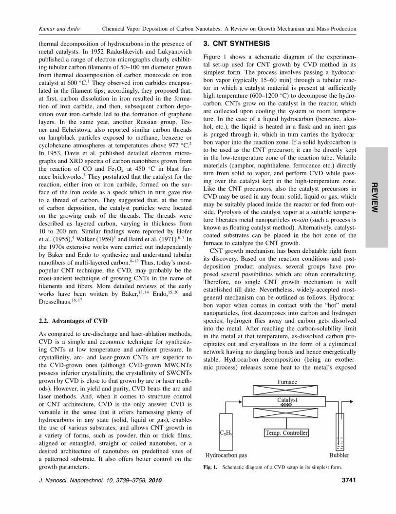
Figure 1 shows a schematic diagram of the experimen-
tal set-up used for CNT growth by CVD method in its
simplest form. The process involves passing a hydrocar-
bon vapor (typically 15–60 min) through a tubular reac-
tor in which a catalyst material is present at sufficiently
high temperature (600–1200 �C) to decompose the hydro-
carbon. CNTs grow on the catalyst in the reactor, which
are collected upon cooling the system to room tempera-
ture. In the case of a liquid hydrocarbon (benzene, alco-
hol, etc.), the liquid is heated in a flask and an inert gas
is purged through it, which in turn carries the hydrocar-
bon vapor into the reaction zone. If a solid hydrocarbon is
to be used as the CNT precursor, it can be directly kept
in the low-temperature zone of the reaction tube. Volatile
materials (camphor, naphthalene, ferrocence etc.) directly
turn from solid to vapor, and perform CVD while pass-
ing over the catalyst kept in the high-temperature zone.
Like the CNT precursors, also the catalyst precursors in
CVD may be used in any form: solid, liquid or gas, which
may be suitably placed inside the reactor or fed from out-
side. Pyrolysis of the catalyst vapor at a suitable tempera-
ture liberates metal nanoparticles in-situ (such a process is
known as floating catalyst method). Alternatively, catalyst-
coated substrates can be placed in the hot zone of the
furnace to catalyze the CNT growth.
CNT growth mechanism has been debatable right from
its discovery. Based on the reaction conditions and post-
deposition product analyses, several groups have pro-
posed several possibilities which are often contradicting.
Therefore, no single CNT growth mechanism is well
established till date. Nevertheless, widely-accepted most-
general mechanism can be outlined as follows. Hydrocar-
bon vapor when comes in contact with the “hot” metal
nanoparticles, first decomposes into carbon and hydrogen
species; hydrogen flies away and carbon gets dissolved
into the metal. After reaching the carbon-solubility limit
in the metal at that temperature, as-dissolved carbon pre-
cipitates out and crystallizes in the form of a cylindrical
network having no dangling bonds and hence energetically
stable. Hydrocarbon decomposition (being an exother-
mic process) releases some heat to the metal’s exposed
Fig. 1. Schematic diagram of a CVD setup in its simplest form.
J. Nanosci. Nanotechnol. 10, 3739–3758, 2010 3741

REVIEW
Chemical Vapor Deposition of Carbon Nanotubes: A Review on Growth Mechanism and Mass Production Kumar and Ando
zone, while carbon crystallization (being an endothermic
process) absorbs some heat from the metal’s precipitation
zone. This precise thermal gradient inside the metal parti-
cle keeps the process on.
Now there are two general cases. (Fig. 2(a)) When the
catalyst–substrate interaction is weak (metal has an acute
contact angle with the substrate), hydrocarbon decomposes
on the top surface of the metal, carbon diffuses down
through the metal, and CNT precipitates out across the
metal bottom, pushing the whole metal particle off the
substrate (as depicted in step (i)). As long as the metal’s
top is open for fresh hydrocarbon decomposition (concen-
tration gradient exists in the metal allowing carbon diffu-
sion), CNT continues to grow longer and longer (ii). Once
the metal is fully covered with excess carbon, its catalytic
activity ceases and the CNT growth is stopped (iii). This
is known as “tip-growth model.”8
In the other case, (Fig. 2(b)) when the catalyst–substrate
interaction is strong (metal has an obtuse contact angle
with the substrate), initial hydrocarbon decomposition and
carbon diffusion take place similar to that in the tip-growth
case, but the CNT precipitation fails to push the metal par-
ticle up; so the precipitation is compelled to emerge out
from the metal’s apex (farthest from the substrate, hav-
ing minimum interaction with the substrate). First, carbon
crystallizes out as a hemispherical dome (the most favor-
able closed-carbon network on a spherical nanoparticle)
which then extends up in the form of seamless graphitic
(a)
(b)
Fig. 2. Widely-accepted growth mechanisms for CNTs: (a) tip-growth model, (b) base-growth model.
cylinder. Subsequent hydrocarbon deposition takes place
on the lower peripheral surface of the metal, and as-
dissolved carbon diffuses upward. Thus CNT grows up
with the catalyst particle rooted on its base; hence, this is
known as “base-growth model.”10
Formation of single- or multi-wall CNT (SWCNT or
MWCNT, respectively) is governed by the size of the cata-
lyst particle.21 Broadly speaking, when the particle size is a
few nm, SWCNT forms; whereas particles—a few tens nm
wide—favor MWCNT formation. With such an approx-
imate growth picture in mind, we can proceed to other
important aspects of the CNT growth. Detailed discussion
on the growth mechanism is presented in Section 5.
CNT synthesis involves many parameters such as hydro-
carbon, catalyst, temperature, pressure, gas-flow rate,
deposition time, reactor geometry. However, to keep our
discussion compact, here we will consider only the three
key parameters: hydrocarbon, catalyst and catalyst support.
3.1. CNT Precursors
Most commonly used CNT precursors are methane,22�23
ethylene,24�25 acetylene,26 benzene,27 xylene,28 and car-
bon monoxide.29 Endo et al.30–32 reported CNT growth
from pyrolysis of benzene at 1100 �C, whereas Jose-
Yacaman et al.33 got clear helical MWCNTs at 700 �Cfrom acetylene. In those cases iron nanoparticles were
used as the catalyst. Later, MWCNTs were also grown
3742 J. Nanosci. Nanotechnol. 10, 3739–3758, 2010
REVIEW
Kumar and Ando Chemical Vapor Deposition of Carbon Nanotubes: A Review on Growth Mechanism and Mass Production
from many other precursors including cyclohexane,34�35
and fullerene.36�37 On the other hand, SWCNTs were first
produced by Dai et al.38 from disproportionation of car-
bon monoxide at 1200 �C, in the presence of molybde-
num nanoparticles. Later, SWCNTs were also produced
from benzene,39 acetylene,40 ethylene,41 methane,23�42
cyclohexane,43 fullerene44 etc. by using various catalysts.
In 2002 Maruyama et al. reported the low-temperature
synthesis of high-purity SWCNTs from alcohol on
Fe–Co-impregnated zeolite support;45 and since then,
ethanol became the most popular CNT precursor in the
CVD method worldwide.46–48 Special feature of ethanol
is that ethanol-grown CNTs are almost free from amor-
phous carbon, owing to the etching effect of OH radical.49
Later, vertically-aligned SWCNTs were also grown on
Mo-Co-coated quartz and silicon substrates.50�51 Recently,
Maruyama’s group has shown that intermittent supply of
acetylene in ethanol CVD significantly assists ethanol in
preserving the catalyst’s activity and thus enhances the
CNT growth rate.52
The molecular structure of the precursor has a detri-
mental effect on the morphology of the CNTs grown.
Linear hydrocarbons such as methane, ethylene, acety-
lene, thermally decompose into atomic carbons or linear
dimers/trimers of carbon, and generally produce straight
hollow CNTs. On the other hand, cyclic hydrocarbons such
as benzene, xylene, cyclohexane, fullerene, produce rel-
atively curved/hunched CNTs with the tube walls often
bridged inside.36�37
General experience is that low-temperature CVD
(600–900 �C) yields MWCNTs, whereas high-temperature
(900–1200 �C) reaction favors SWCNT growth. This indi-
cates that SWCNTs have a higher energy of formation
(presumably owing to small diameters; high curvature
bears high strain energy). Perhaps that is why MWCNTs
are easier to grow (than SWCNTs) from most of the hydro-
carbons, while SWCNTs grow from selected hydrocarbons
(viz. carbon monoxide, methane, etc. which have a reason-
able stability in the temperature range of 900–1200 �C).Commonly efficient precursors of MWCNTs (viz. acety-
lene, benzene, etc.) are unstable at higher temperature and
lead to the deposition of large amounts of carbonaceous
compounds other than the nanotubes.
In 2004, using ethylene CVD, Hata et al. reported
water-assisted highly-efficient synthesis of impurity-free
SWCNTs on Si substrates.53 They proposed that con-
trolled supply of steam into the CVD reactor acted as a
weak oxidizer and selectively removed amorphous carbon
without damaging the growing CNTs. Balancing the rel-
ative levels of ethylene and water was crucial to maxi-
mize the catalyst’s lifetime. However, very recently, Zhong
et al. have shown that a reactive etchant such as water or
hydroxyl radical is not required at all in cold-wall CVD
reactors if the hydrocarbon activity is low.54 These studies
emphatically prove that the carbon precursor plays a cru-
cial role in CNT growth. Therefore, by proper selection of
CNT precursor and its vapour pressure, both the catalyst’s
lifetime and the CNT-growth rate can be significantly
increased; and consequently, both the yield and the quality
of CNTs can be improved.
3.2. CNT Catalysts
For synthesizing CNTs, typically, nanometer-size metal
particles are required to enable hydrocarbon decomposition
at a lower temperature than the spontaneous decomposi-
tion temperature of the hydrocarbon. Most commonly-used
metals are Fe, Co, Ni, because of two main reasons: (i) high
solubility of carbon in these metals at high temperatures;
and (ii) high carbon diffusion rate in these metals. Besides
that, high melting point and low equilibrium-vapor pres-
sure of these metals offer a wide temperature window of
CVD for a wide range of carbon precursors. Recent con-
siderations are that Fe, Co, and Ni have stronger adhesion
with the growing CNTs (than other transition metals do)
and hence they are more efficient in forming high-curvature
(low-diameter) CNTs such as SWCNTs.55
Solid organometallocenes (ferrocene, cobaltocene, nick-
elocene) are also widely used as a CNT catalyst, because
they liberate metal nanoparticles in-situ which catalyze the
hydrocarbon decomposition more efficiently. It is a gen-
eral experience that the catalyst-particle size dictates the
tube diameter. Campbell’s group has reported the particle-
size dependence and a model for iron-catalyzed growth
of CNTs.37 Hence, metal nanoparticles of controlled size,
pre-synthesized by other reliable techniques, can be used
to grow CNTs of controlled diameter.56 Thin films of cat-
alyst coated on various substrates are also proven good
in getting uniform CNT deposits.24 The key factor to get
pure CNTs is achieving hydrocarbon decomposition on the
catalyst surface alone, and prohibiting the aerial pyrolysis.
Apart from the popular transition metals (Fe, Co, Ni),
other metals of this group, such as Cu, Au, Ag, Pt, Pd
were also found to catalyze various hydrocarbons for CNT
growth. A comprehensive review of the role of metal par-
ticles in the catalytic growth of CNTs has been published
by Kauppinen’s group.57
On the role of CNT catalysts, it is worth mention-
ing that transition metals are proven to be efficient cat-
alysts not only in CVD but also in arc-discharge and
laser-vaporization methods. Therefore, it is likely that
these apparently different methods might inherit a com-
mon growth mechanism of CNT, which is not yet clear.
Hence this is an open field of research to correlate dif-
ferent CNT techniques in terms of the catalyst’s role in
entirely different temperature and pressure range.
3.3. CNT Catalyst Supports
The same catalyst works differently on different support
materials. Commonly used substrates in CVD are
graphite,8�9 quartz,58�59 silicon,53�60 silicon carbide,61�62
J. Nanosci. Nanotechnol. 10, 3739–3758, 2010 3743
REVIEW
Chemical Vapor Deposition of Carbon Nanotubes: A Review on Growth Mechanism and Mass Production Kumar and Ando
silica,63�64 alumina,65�66 alumino-silicate (zeolite),67�68
CaCO3,69 magnesium oxide,70–72 etc. For an efficient CNT
growth, the catalyst–substrate interaction should be inves-
tigated with utmost attention. Metal–substrate reaction
(chemical bond formation) would cease the catalytic behav-
ior of the metal. The substrate material, its surface mor-
phology and textural properties greatly affect the yield and
quality of the resulting CNTs. Zeolite supports with cat-
alysts in their nanopores have resulted significantly high
yields of CNTs with a narrow diameter distribution.68�73
Alumina materials are reported to be a better catalyst sup-
port than silica owing to the strong metal–support inter-
action in the former, which allows high metal dispersion
and thus a high density of catalytic sites.74 Such interac-
tions prevent metal species from aggregating and forming
unwanted large clusters that lead to graphite particles or
defective MWCNTs.75 Recent in-situ XPS analysis of CNT
growth from different precursors on iron catalyst supported
on alumina and silica substrates have confirmed these the-
oretical assumptions.64 Thin Alumina flakes (0.04–4 �mthick) loaded with iron nanoparticles have shown high
yields of aligned CNTs of high aspect ratio.76 Latest con-
siderations are that the oxide substrate, basically used as
a physical support for the metal catalyst, might be play-
ing some chemistry in the CNT growth.77 Acoordingly,
the chemical state and structure of the substrate are more
important than that of the metal.
3.4. New (Uncommon) CNT Catalysts
Recent developments in the nanomaterials synthesis and
characterization have enabled many new catalysts for the
CNT growth. Apart from popularly used transition met-
als (Fe, Co, Ni), a range of other metals (Cu, Pt, Pd,
Mn, Mo, Cr, Sn, Au, Mg, Al) has also been successfully
used for horizontally-aligned SWCNT growth on quartz
substrates.78 Unlike transition metals, noble metals (Au,
Ag, Pt, Pd etc.) have extremely low solubility for car-
bon, but they can dissolve carbon effectively for CNT
growth when their particle size is very small (<5 nm).79�80
Daisuke et al. have succeeded in controlled growth of
SWCNTs on Au nanoparticles deposited on atomic steps
of Si. It has been proposed that the active catalyst is Au–Si
alloy with about 80 at% Au.71
Although copper is a transition metal, it showed insignif-
icant catalytic effect on the CNT growth in the past.82–85 In
fact, it had been considered as an adverse contaminant. As a
recent development, however, it has been found to catalyze
the CNT growth efficiently. Methane and ethanol decom-
position at 825–925 �C on Cu nanoparticles supported on
silicon wafers produced high densities of well-crystallined
SWCNTs up to 1 cm in length.86 The Cu nanoparticles
were synthesized by the reduction of CuCl2 in the pres-
ence of Cu2O nanoparticles produced by the thermolysis
of cupric formates in coordinating solvents.87 This implies
that the novelty lies in the catalyst-preparation method.
Rhenium (Re) is a rare catalyst used for CNT growth.
Diamagnetic SWCNTs and MWCNTs were reported by
methane decomposition on Re catalyst.88 The current sce-
nario is that, just as any carbon-containing material can
yield CNT, any metal can catalyze the CNT growth,
provided that the experimental conditions are properly
optimized.
3.5. Metal-Free CNT Growth
Very recently nanodiamond particles (5 nm) were suc-
cessfully used as a CNT catalyst. Ethanol suspension of
nanodiamond particles was spread on graphite plates and
dried in air at 600 �C. This resulted in isolated dia-
mond particles, monolayers of diamond, and multilayered-
diamond stacks on the substrate, depending upon the dia-
mond concentration (0.01–1.0 wt%). Ethanol CVD over
these diamond-loaded substrates at 850 �C produced iso-
lated CNTs, layered CNTs and high-density CNT mats,
respectively. The nanodiamond particles do not fuse even
after high-temperature CVD process, implying that they
remain in solid state during CVD. Nanodiamond is there-
fore said to act as a CNT growth seed.89 This result proves
that CNT growth is possible without metal catalyst. Does
nanodiamond act as a catalyst? If it does, how? These are
open questions.
In many studies, oxygen was noticed to activate the CNT
growth. Recent studies have revealed that many metals,
which do not exhibit catalytic activity in pure-metal form,
do well in oxide form.90 Does metal oxide act as a cata-
lyst? Template-free directional growth of CNTs has been
achieved on sapphire.91 CNTs have also been grown on
semiconductors such as Si and Ge nanoparticles (though
C has little solubility in bulk Si or Ge), provided that the
nanoparticles are heated in air just before CVD.92 Simi-
larly, CNT growth on SiC substrates takes place only when
some oxygen is present in the chamber.93 Porous Al2O3
has already been shown to facilitate CNT growth without
any catalyst.94�95 Catalyst-free CNT growth is also possible
in oxy-fuel flames.96 And oxide, typically used as a cata-
lyst support in CVD, is itself capable of forming graphene
layers.97 All these examples resoundingly indicate that oxy-
gen plays a key role in CNT growth. The question is: is
it a catalyst? HRTEM investigation of the CNTs grown
by cyclohexane pyrolysis over iron nanoparticles supported
on thin Al2O3 layers shows that CNT keeps on growing
even when the metal is completely encapsulated in the tube
center.98 The authors propose that the metal only helps to
initiate the CNT precipitation at the nucleation stage. Once
the CNT head is created, metal becomes non functional;
subsequent carbon addition to the CNT base periphery is
facilitated by the substrate’s oxide layer. This concept is
radically different to the existing concept that the metal
must remain exposed (either on the CNT tip or base) to
keep the growth on. Hence more careful in-situ observation
3744 J. Nanosci. Nanotechnol. 10, 3739–3758, 2010
REVIEW
Kumar and Ando Chemical Vapor Deposition of Carbon Nanotubes: A Review on Growth Mechanism and Mass Production
and robust theoretical support are required to establish the
oxide’s direct role as a catalyst.
The latest development of the field is even more excit-
ing. CNT growth is possible with no metal at all; the
non-metallic substrate itself acts as the catalyst. Liu et al.
passed methane and hydrogen (1:1) over an SiO2-sputtered
Si wafer at 900 �C for 20 min and got dense SWCNTs
grown on it. In the same CVD condition, thermally-grown
SiO2 films did not result CNTs. The success lies in the
in-situ transformation of the sputtered SiO2 film (30 nm)
into isolated Si particles (1.9 nm) which efficiently cat-
alyzed methane decomposition due to small-size effect.99
Similar SiO2 nanoparticle generation and subsequent CNT
growth was reported by Liu et al. from ethanol decom-
position on annealed SiO2/Si substrates.100 On the other
hand, Huang et al. simply scratched the existing SiO2/Si
wafers by a diamond blade and passed ethanol over it
at 900 �C for 10 min.101 Bunch of SWCNTs grew on
the scratched portions. Random scratches on thin SiO2
films protrude some nanoparticles mechanically. These
developments raise many new questions and compel us
to reconsider the existing CNT-growth models. SiO2 has
no carbon solubility; how does it assist hydrocarbon-to-
CNT conversion? Does it act as a solid-state catalyst like
nanodiamond? Or does it melt at 900 �C as usual metal
nanoparticles do? If it is in molten state, Si and O atoms
might have some mobility thus creating a vacancy or dis-
location which would attract hydrocarbon and cause dehy-
drogenation. If it is in solid state, it would be strained
enough (high curvature at small particle size) and could
possibly interact with hydrocarbon. It is also likely that
it is in a quasi-liquid (fluctuating solid) state; slight dis-
tortion in its overall shape would develop some polar-
ity on Si and O atoms, which could possibly facilitate
dehydrogenation; and its fluctuating shape could act as
a template for tubular graphite formation. These specu-
lations evoke serious discussion. SiO2 has a number of
distinct crystalline forms. Si–O bond length and Si–O–Si
bond angle vary significantly in different crystal forms
(e.g., 154–171 pm, 140�–180�). Ab-initio calculations have
indicated that CNT-cap nucleation is influenced by solid-
surface curvatures.102 More theoretical considerations and
experimental verifications are sought for proper under-
standing of CNT growth on SiO2 nanoparticles. It will take
due time to come up with a convincing model; neverthe-
less, there is no doubt that metal-free CNT synthesis is a
major breakthrough in CNT research, and it has opened
up a new avenue in nanotechnology.
3.6. New (Unconventional) CNT Precursors
Apart from the popular hydrocarbons mentioned in
Section 3.1, CNTs have also been synthesized from
many other organic compounds, especially from poly-
mers. Carbonization (prolonged pyrolysis in vacuum
to convert organic compounds into solid carbon) of
polyacrylonitrile103 and poly-furfuryl-alcohol104 within
nanoporous alumina templates resulted in thick CNTs.
Reported in 1995–96, this was a multi-step tedious pro-
cess requiring chemically-controlled monomer initiators
to achieve polymerization. The field has matured enough
and nowadays super-aligned highly-uniform CNTs can be
produced from readily available polymers without taking
pains for chemical initiators or catalysts. Recently, sev-
eral polymer precursors, loaded on commercially-available
alumina templates of well-defined pore size, were car-
bonized (400–600 �C for 3 h) to obtain MWCNTs of
desired diameter.105 N-doped MWCNTs obtained from
carbonization of polypyrrole within alumina and zeolite
membranes have shown better hydrogen-storage capacity
than pristine MWCNTs obtained from polyphenyl acety-
lene in the same conditions.106 As for SWCNT, pyroly-
sis of tripropylamine within the nanochannels (0.73 nm)
of aluminophosphate crystals (AFI) resulted in the small-
est nanotubes (0.4 nm).107 Later, several carbon precursors
were pyrolyzed within the AFI channels and tetrapropy-
lammonium hydroxide was found to yield high densities
of 4Å CNTs with better crystallinity.108 It is suggested
that the number of carbon atoms in the precursor molecule
influences the SWCNT packing density in the template
channels.
Among other organic compounds, amino-dichloro-s-
triazine, pyrolyzed on cobalt-patterned silica substrates,
resulted in highly pure CNTs.109 Almost contemporary,
organometallic compounds such as metallocene (ferrocene,
cobaltocene, nickelocene)27 and nickel phthalocyanine110
were used as the carbon-cum-catalyst precursor; however,
as-grown CNTs were highly metal-encapsulated and the
yield was very low. Later, pyrolysis of thiophene with met-
allocene led to the formation of Y -junction CNTs.111�112
Recently, high-temperature pyrolysis (1300 �C) of simple
saccharides (from table sugar (sucrose) to lactose) resulted
in straight as well as helical MWCNTs.113
In 2001 high yield of CNTs was obtained from camphor,
a tree product.114 Since then the authors remained involved
with this environment-friendly source of CNTs and
established the conditions for growing MWCNTs,115�116
SWCNTs,117 and vertically-aligned CNTs on quartz and
silicon substrates59�60�118 using ferrocene catalyst. Later,
using Fe–Co catalyst impregnated in zeolite support,
mass production of CNTs was achieved by camphor
CVD.68�119 MWCNTs were grown at a temperature as low
as 550 �C, whereas SWCNTs could be grown at rela-
tively high (900 �C) temperature. Because of very low cat-
alyst requirement with camphor, as-grown CNTs are least
contaminated with metal, whereas oxygen atom present
in camphor helps in oxidizing amorphous carbon in-situ.These features of camphor stimulated more in-depth, basic
and applied research worldwide. Collaboration of India,
UK and Japan reported the use of camphor-grown CNTs
J. Nanosci. Nanotechnol. 10, 3739–3758, 2010 3745
REVIEW
Chemical Vapor Deposition of Carbon Nanotubes: A Review on Growth Mechanism and Mass Production Kumar and Ando
as the anode of secondary lithium battery.120 Scientists
at the University of Edinburgh investigated the effect of
camphor’s molecular structure on the CNT growth and
quality.121 Researchers at Tokyo University of Science
studied camphor CVD with different ways of catalyst feed-
ing and addressed catalyst activation/deactivation process
for the synthesis of highly-dense aligned CNT arrays.122
Another Japanese group synthesized aligned CNTs from
camphor and reported their field emission properties.123�124
South African scholars studied the effect of carrier gases
(nitrogen, argon, argon–hydrogen mixture) as well as
catalyst–support materials (SiO2, Al2O3 and MgO) on the
quality of camphor-grown CNTs.125 Brazilian scientists
carried out thermal annealing and electrochemical purifi-
cation of camphor-grown CNTs.126 Chinese carbon group
synthesized tree-like multi-branched CNTs from camphor
and reported the effects of temperature, argon flow rate and
catalyst concentration on the structure of as-grown carbon
nanotrees.127 Italian carbon group investigated different
aspects of camphor-CVD and published a series of reports.
Musso et al. achieved low-temperature (650 �C) growth
of vertically-aligned CNTs on various glass substrates and
confirmed the high CNT-growth efficiency of camphor.128
Porro et al. optimized the CNT growth parameters by
Taguchi method and got 2.3 mm thick CNT mats at a
high deposition rate of 500 nm/sec.129�130 Later, the same
group published fluid-dynamic analysis of the carrier-gas
flow for camphor-CVD system131�132 and hydrogen-storage
analysis of different kinds of CNTs.133 Thus, camphor has
emerged as a promising and the most-efficient CNT pre-
cursor amongst the new/unconventional ones. Moreover, it
has opened up a new avenue of exploring other botani-
cal products as a CNT precursor. Appreciable efforts have
been made in India by Sharon and his coworkers who
investigated the pyrolysis of a range of plant-based mate-
rials for this purpose.134 Recently, high yields of aligned
and non-aligned CNTs have also been reported from other
plant-derived cheap raw materials such as turpentine135–137
and eucalyptus oils.138
Apart from the well-defined chemical reagents described
above, CNTs have also been successfully and systemati-
cally synthesized from domestic fuels such as kerosene,139
coal gas,140 and liquefied petroleum gas.141 More interest-
ingly, there are scientific reports of CNT production from
green grasses. Grass contains dense vascular bundles in
the stem and branches. They are mainly composed of cel-
lulose, hemicellulose and lignin. Rapid heat treatment of
grass (600 �C) in controlled-oxygen ambience dehydrates
and carbonizes the vascular bundles into CNTs.142 Thus,
now it is almost certain that any carbon-containing mate-
rial may be a CNT precursor under suitable experimental
conditions. The point is: can we reproduce the product
quality and quantity from those materials of inconsistent
composition? Certainly not. Depending upon the chemical
composition of the raw material, one will have to change
the experimental conditions every now and then; and the
impurity elements of the raw material would greatly con-
taminate the resulting CNTs which would ultimately be of
no practical importance. Hence, these novel and interest-
ing researches of CNT production from garbage materials
seem to be too long-term project. To meet the immediate
need of mass production of CNTs, it is advisable to choose
a raw material of consistent chemistry, which is highly
abundant and regenerative too; so that it could lead to a
reproducible as well as sustainable industrial technique.
4. CNT GROWTH CONTROL
It is well known that hydrocarbons are easily broken at
high temperatures. Such a thermal decomposition is called
Pyrolysis. However, in the presence of suitable metal cat-
alysts, a hydrocarbon can be decomposed at lower tem-
peratures (catalytic pyrolysis). The key of CNT growth by
CVD is to achieve the hydrocarbon decomposition on the
metal surface alone and prohibit spontaneous aerial pyrol-
ysis (do not allow the hydrocarbon to break uncatalyzed,
beyond the catalyst surface). Restriction of pyrolysis to
the catalyst surface is controlled through proper selection
of hydrocarbon and catalyst materials, vapor pressure of
the hydrocarbon, concentration of the catalyst, and the
CVD reaction temperature. Choosing camphor as the car-
bon source, the rest three key parameters were categori-
cally optimized in our laboratory.
4.1. Effect of Catalyst Material and Concentration
Early experiments of CNTs were carried out with dif-
ferent metal catalysts (Fe, Co, Ni) separately. Iron was
found to have high catalytic effect in hydrocarbon decom-
position leading to higher CNT deposits, but those CNTs
were poorly graphitized.22 On the other hand, cobalt cata-
lyst resulted in better-graphitized CNTs but the yield went
down.73 Hence a mixture of the two metals were tried to
combine their individual advantages, and it was success-
ful. Large volumes of well-graphitized MWCNTs were
obtained. Additional advantage of using the bimetallic cat-
alyst was that CNTs could be grown at much lower tem-
perature viz. 550 �C. It is because the melting point of the
mixture of Fe and Co is lower than their individual melting
points. Moreover, alloys are known to be better catalysts
than pure metals. These trends suggest that tri-metallic cat-
alysts should also give interesting results, though the inter-
pretation of result would be more complicated. No much
effort is known in this direction.
Besides the catalyst material, the catalyst concentration
also plays an important role in the CNT growth. In our lab,
catalyst concentration in zeolite was varied in a wide range
(1–50 wt%). No CNT formed for a catalyst concentration
less than 2.4 wt% in zeolite. Lower catalyst concentrations
(2.4–5%) exhibited SWCNT growth (at 850 �C and above),
3746 J. Nanosci. Nanotechnol. 10, 3739–3758, 2010

REVIEW
Kumar and Ando Chemical Vapor Deposition of Carbon Nanotubes: A Review on Growth Mechanism and Mass Production
whereas higher concentrations favored MWCNT growth.
A combined Fe+ Co concentration of 40% accounted
for the highest yield of MWCNTs with negligible metal
contamination.119 These studies confirm that SWCNTs or
MWCNTs can be selectively grown by proper selection of
catalyst materials and their concentration.
4.2. Effect of Temperature
The authors investigated the effect of temperature on cam-
phor CVD in a wide range of 500–1000 �C. It was noticedthat camphor did not decompose below 500 �C. At 550 �Cvery short-length tubes emerged from the zeolite pores
suggesting that the catalyst activity, and hence the CNT
growth rate, was quite low at 550 �C (Fig. 3(a)). How-
ever, the CNT growth abruptly increased at 600 �C, anda profound growth was observed all around the zeolite
pores (Fig. 3(b)). At 650�C and above, the growth rate
was so enormous that hardly a zeolite particle could be
located amid nanotubes. TEM investigations revealed that
the CNT diameter increased with the increasing growth
temperature. Very clean CNTs, almost free from metal-
lic impurity, were produced up to 750 �C. This suggests
that, at low temperatures, the catalyst–support interaction is
strong enough not to let the metal particles leave the zeolite
(a) (b)
20 nm 40 nm
60 nm
(c) (d)
Fig. 3. TEM images of MWCNTs grown at low temperatures and atmospheric pressure: (a) 550 �C, (b) 600 �C, (c) 900 �C, (d) SWCNTs at 900 �C.Reprinted with permission from [68], M. Kumar and Y. Ando, Carbon 43, 533 (2005). © 2005, Elsevier Science.
matrix. So, the CNTs grow via base-growth process. How-
ever, at higher temperatures, the metal particles were grad-
ually pronounced in the samples, preferably encapsulated
at the CNT tips. This suggests that, at critical temperatures,
tip-growth process coexists with base-growth process, due
to inhomogenity of metal dispersion. Bigger metal clus-
ters may leave a part of it to be lifted up with the growing
CNTs.
From 750 �C onward, both the diameter and the
diameter-distribution range increased drastically. It is
supposed that, at high temperature, the metal atoms
agglomerate into bigger clusters leading to thick CNTs.
Simultaneously; high temperature promotes camphor
decomposition leading to more carbon generation and
hence more wall formation. At 850 �C and above, SWC-
NTs began to form besides MWCNTs and the volume
of SWCNTs increased with the increasing temperature.
For instance, in 900 �C sample (Fig. 3(c)) large bun-
dles of SWNTs can be seen (in low contrast) under-
neath thick fibers (in high contrast). It is noteworthy that,
while MWCNTs and fibers have a lot of metal contam-
ination, there is no trace of metal associated with the
SWCNT bundles (Figs. 3(c, d)). Thus, the best temper-
ature for a gigantic growth of MWCNTs, was found to
be 650 �C, as optimized for Fe–Co-impregnated zeolite
J. Nanosci. Nanotechnol. 10, 3739–3758, 2010 3747
REVIEW
Chemical Vapor Deposition of Carbon Nanotubes: A Review on Growth Mechanism and Mass Production Kumar and Ando
catalyst. CNTs grown at such a low temperature were
almost free from metal particles as well as amorphous car-
bon. On the other hand, the best temperature for SWCNT
growth from camphor on Fe–Co–zeolite system was noted
to be 900 �C, restricting the total metal concentration (Fe+Co) to 2.4 wt% in zeolite (Fig. 3(d)). In such a low concen-
tration, the metal content remains confined to the zeolite
host even at 900 �C, and does not contaminate the growing
SWCNTs. Thus, the CVD temperature plays the central
role in CNT growth. For a fixed metal concentration, the
increasing CVD temperature increases the diameter distri-
bution. On the other hand, MWCNTs and SWCNTs can
be selectively grown as a function of CVD temperature,
if the catalyst’s concentration is properly optimized.68 A
good account of the effect of temperature on the growth
and structure of CNTs is reported by Li et al.143
4.3. Effect of Vapor Pressure
For controlled growth of CNTs by CVD, the vapor pres-
sure of the hydrocarbon in the reaction zone is another
very important parameter. For gaseous hydrocarbons, a
desired vapor pressure in the CVD reactor can be main-
tained by limited gas-flow rate and controlled suction with
a rotary pump.144 In the case of a liquid hydrocarbon,
its vapor pressure is controlled by its heating tempera-
ture before it enters the reactor.145 However, for a solid
hydrocarbon such as camphor, it is quite tricky to con-
trol its vapor pressure. It becomes a function of three
parameters: camphor mass, its vaporization temperature,
and the flow rate of argon—the carrier gas. By proper
optimization of these three parameters, the influx of cam-
phor vapor to the zeolite bed and its decomposition rate
were balanced to a great extent, and a record growth of
MWCNTs was achieved at atmospheric-pressure CVD.119
On the other hand, pure SWCNTs (free from MWCNTs)
were selectively obtained from camphor CVD at low pres-
sures (10–40 torr) where the camphor vapor pressure is
quite in tune with the low metal concentration.68 Unfortu-
nately, however, the quantity of such pure SWCNTs is still
in milligram order. Gram-order SWCNT synthesis from
camphor is still an open field of research.
5. CNT GROWTH MECHANISM UNDERELECTRON MICROSCOPY
As briefly outlined in Section 3, most widely-accepted
CNT growth model assumes that the hydrocarbon vapor
is adsorbed to the metal nanoparticles; and catalytically-
decomposed carbon species diffuse through the metal par-
ticle, and upon reaching supersaturation, precipitate out
in the form of seamless carbon cylinder. However, the
points of discord here are whether the metal is in solid
or liquid form, whether this diffusion is volume diffusion
or surface diffusion, whether the actual catalyst for CNT
growth is the pure metal or metal carbide, etc. Let us now
review some important in-situ electron microscopic studies
on these aspects.
5.1. Physical State of the Catalyst
The first effort to observe the carbon filament growth
process in-situ was made by Baker et al.8 By installing
a gas-reaction cell in the TEM specimen chamber, they
were able to perform carbon fiber growth in a tempera-
ture range of 600–1200 �C at different gas pressures up to
225 torr (maximum), while the TEM column was main-
tained at sufficiently low temperature and pressure suitable
for electron microscopy. For acetylene decomposition on
nickel catalyst supported on silica and graphite supports
at 600 �C, they clearly observed that the metal particles
changed it shape and moved up with a trail of carbon
deposit (30–50 nm diameter). From the changing shape
of the metal particle during fiber growth, they assumed
that the catalyst was in liquid phase. The activation energy
calculated for this growth was nearly same as the acti-
vation energy of carbon diffusion in liquid nickel; hence
they suggested that carbon diffuses through the bulk metal
and the fiber growth rate is diffusion-controlled. Simi-
lar tip-growth process was observed with Fe, Co and Cr
catalysts.9 But in the case of acetylene decomposition on
bimetallic (Pt–Fe) catalyst, the catalyst was observed to
remain static on the substrate, while the carbon filament
went on growing up. This led them to enunciate base-
growth model.10 It was explained that strong interaction
between Pt–Fe and SiO2 substrate kept the metal particle
anchored to the substrate surface, and carbon precipitation
occurred from the free upper face of the particle. Temper-
ature and concentration gradients were thought to be the
main driving forces for the continued growth dynamics.
The filament growth was seen to be ceased when the par-
ticle was fully covered with the carbon cloud, but it could
be re-activated by exposure to either hydrogen or oxygen
at higher temperatures.8 Later, however, many scientists
reported base-grown CNTs from Fe and Co catalysts on Si
and SiO2 substrates.7�60�146�147 This indicates that the same
set of hydrocarbon, catalyst and substrate may act differ-
ently in slightly different experimental conditions (temper-
ature, pressure, etc.).
In 1984 Gary Tibbetts explained why catalytically-
grown carbon nanofibers were tubular.148 Because the sur-
face free energy of the (002) basal plane of graphite is
exceptionally low, the free energy required for a filament
growth is minimum when graphite is in the form of a
seamless cylinder circumfering the metal. And the inner
core is hollow because inner cylindrical planes of small
diameter would be highly strained, energetically unfavor-
able to form. He also explained the CNT growth mech-
anism with a vapor–liquid–solid (VLS) model, originally
formulated for Si, Ge whiskers and many other crystals.149
3748 J. Nanosci. Nanotechnol. 10, 3739–3758, 2010
REVIEW
Kumar and Ando Chemical Vapor Deposition of Carbon Nanotubes: A Review on Growth Mechanism and Mass Production
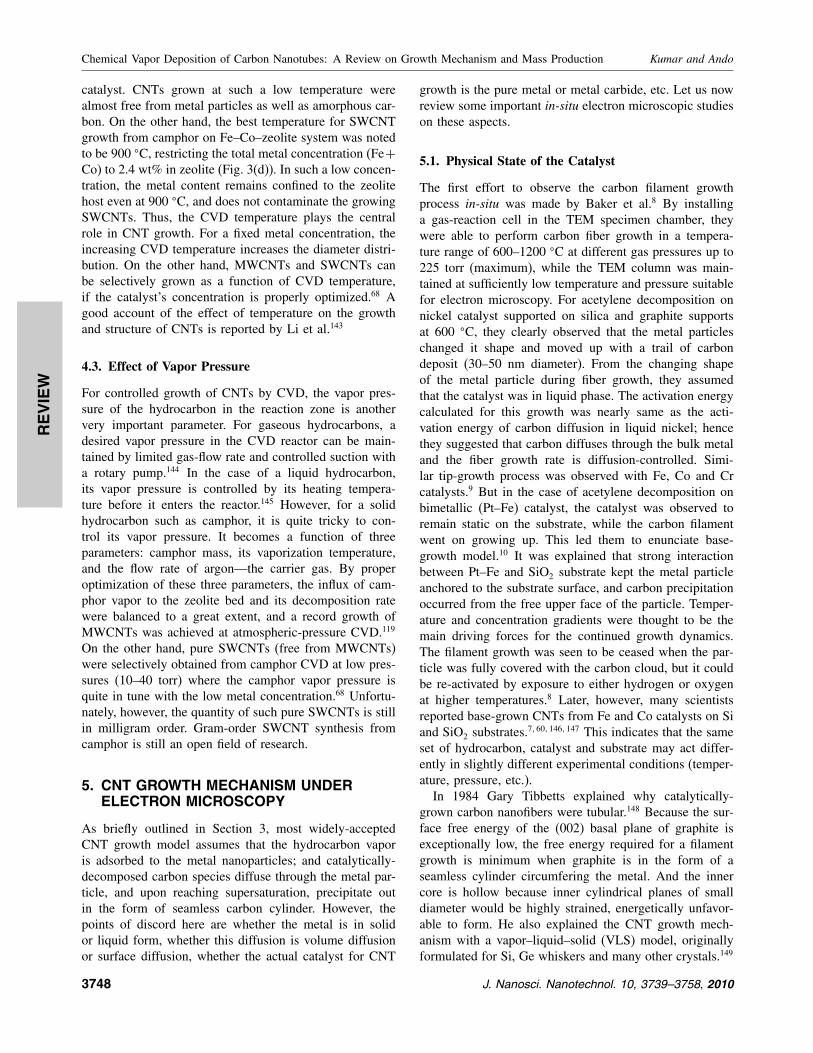
Fig. 4. Melting temperature of selected metals as a function of particle
diameter. Reprinted with permission from [57], A. Moisala et al., J. Phys.:Condens. Mater. 15, S3011 (2003). © 2003, IOP Publishing Ltd.
Although this model is convincing and acceptable to a
great extent, it is often doubted how Fe, Co, Ni etc (normal
melting point ∼1500 �C) could be in liquid state within
600–900 �C, the growth temperature of typical CNTs in
CVD. Here it is important to note that the melting point
of nanoparticles below 10 nm falls abruptly (Fig. 4). For
instance, a 5-nm Fe and Co particle can melt at about
850 �C and 640 �C, respectively. These values (melting
points) fall on the border line casting the probability of
50–50 for both solid and liquid states of the metal. So it
is still hard to say on the metal’s physical state authorita-
tively. However, recalling that hydrocarbon decomposition
on metal surface is an exothermic reaction, it is likely that
the extra heat generated during hydrocarbon decomposi-
tion helps metal liquefaction to some extent. Hence the
(a) (b) (c) (d)
(e) (f) (g) (h)
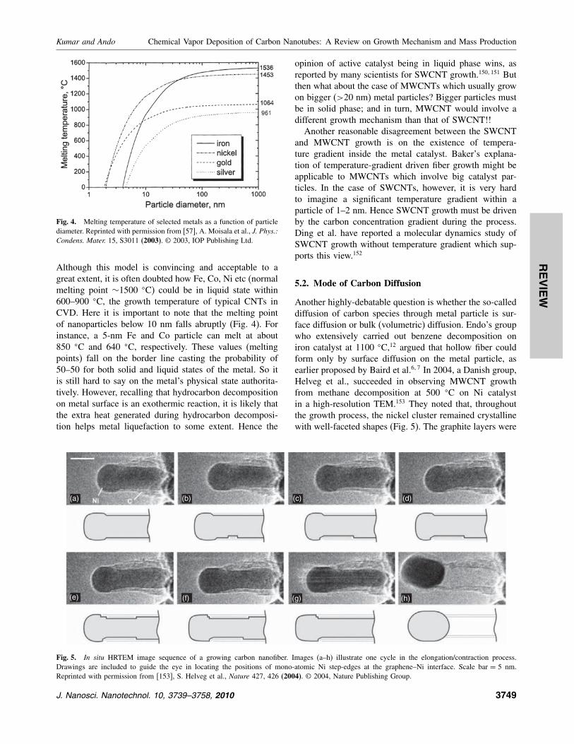
Fig. 5. In situ HRTEM image sequence of a growing carbon nanofiber. Images (a–h) illustrate one cycle in the elongation/contraction process.
Drawings are included to guide the eye in locating the positions of mono-atomic Ni step-edges at the graphene–Ni interface. Scale bar = 5 nm.
Reprinted with permission from [153], S. Helveg et al., Nature 427, 426 (2004). © 2004, Nature Publishing Group.
opinion of active catalyst being in liquid phase wins, as
reported by many scientists for SWCNT growth.150�151 But
then what about the case of MWCNTs which usually grow
on bigger (>20 nm) metal particles? Bigger particles must
be in solid phase; and in turn, MWCNT would involve a
different growth mechanism than that of SWCNT!!
Another reasonable disagreement between the SWCNT
and MWCNT growth is on the existence of tempera-
ture gradient inside the metal catalyst. Baker’s explana-
tion of temperature-gradient driven fiber growth might be
applicable to MWCNTs which involve big catalyst par-
ticles. In the case of SWCNTs, however, it is very hard
to imagine a significant temperature gradient within a
particle of 1–2 nm. Hence SWCNT growth must be driven
by the carbon concentration gradient during the process.
Ding et al. have reported a molecular dynamics study of
SWCNT growth without temperature gradient which sup-
ports this view.152
5.2. Mode of Carbon Diffusion
Another highly-debatable question is whether the so-called
diffusion of carbon species through metal particle is sur-
face diffusion or bulk (volumetric) diffusion. Endo’s group
who extensively carried out benzene decomposition on
iron catalyst at 1100 �C,12 argued that hollow fiber could
form only by surface diffusion on the metal particle, as
earlier proposed by Baird et al.6�7 In 2004, a Danish group,
Helveg et al., succeeded in observing MWCNT growth
from methane decomposition at 500 �C on Ni catalyst
in a high-resolution TEM.153 They noted that, throughout
the growth process, the nickel cluster remained crystalline
with well-faceted shapes (Fig. 5). The graphite layers were
J. Nanosci. Nanotechnol. 10, 3739–3758, 2010 3749
REVIEW
Chemical Vapor Deposition of Carbon Nanotubes: A Review on Growth Mechanism and Mass Production Kumar and Ando
found to grow as a consequence of dynamic interaction
between carbon and nickel atoms. ‘Surface atoms’ of the
nickel cluster moved up and down, in and out (continu-
ously changing the metal’s surface texture) as if they were
knitting a graphene sheet out of the surrounding carbon
atoms. The nanocluster shape was periodically changing
its shape from spherical to cylindrical to align the graphene
layers around them. The authors proposed that the mono-
atomic steps on the cluster boundary played a key role
in anchoring carbon atoms and weaving the graphene net-
work. This observation reveals that the catalyst cluster is in
solid phase and the carbon diffusion is a surface diffusion
around the catalyst.
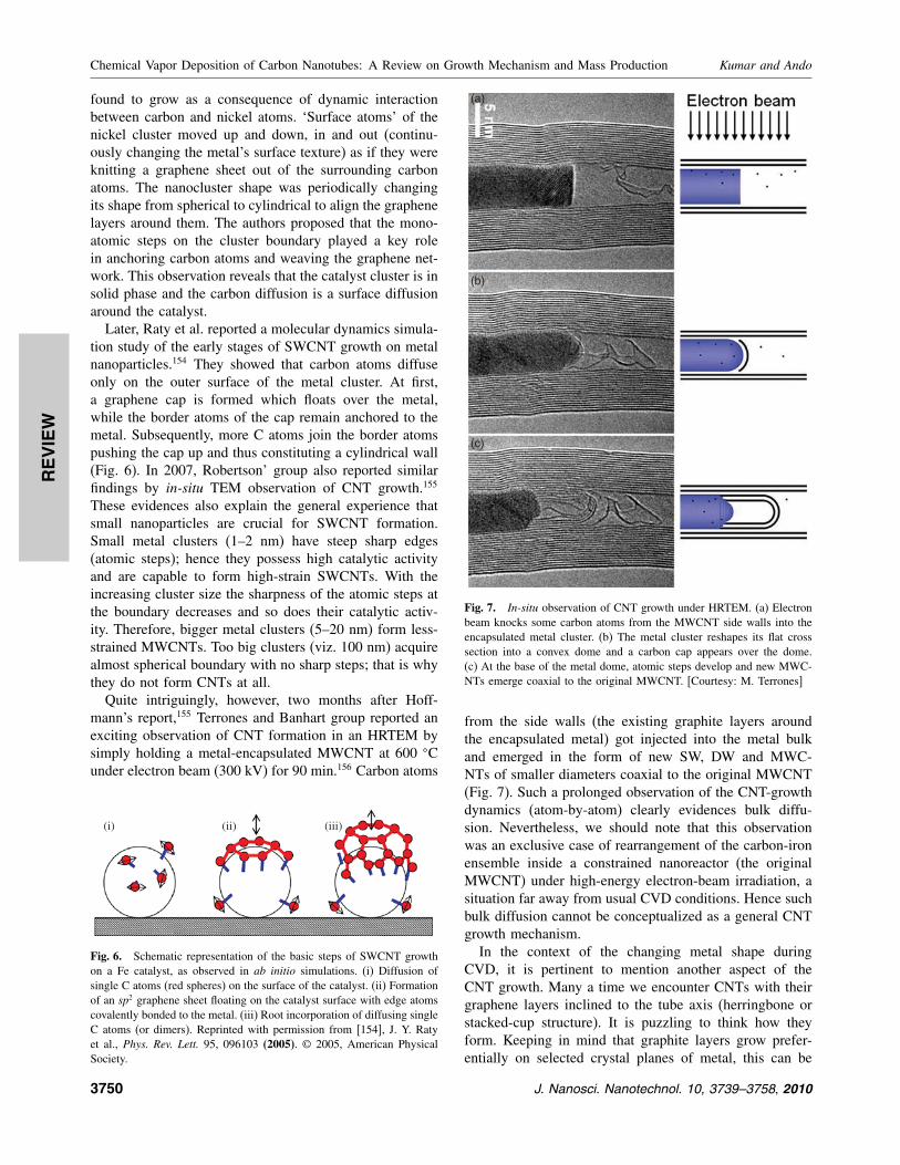
Later, Raty et al. reported a molecular dynamics simula-
tion study of the early stages of SWCNT growth on metal
nanoparticles.154 They showed that carbon atoms diffuse
only on the outer surface of the metal cluster. At first,
a graphene cap is formed which floats over the metal,
while the border atoms of the cap remain anchored to the
metal. Subsequently, more C atoms join the border atoms
pushing the cap up and thus constituting a cylindrical wall
(Fig. 6). In 2007, Robertson’ group also reported similar
findings by in-situ TEM observation of CNT growth.155
These evidences also explain the general experience that
small nanoparticles are crucial for SWCNT formation.
Small metal clusters (1–2 nm) have steep sharp edges
(atomic steps); hence they possess high catalytic activity
and are capable to form high-strain SWCNTs. With the
increasing cluster size the sharpness of the atomic steps at
the boundary decreases and so does their catalytic activ-
ity. Therefore, bigger metal clusters (5–20 nm) form less-
strained MWCNTs. Too big clusters (viz. 100 nm) acquire
almost spherical boundary with no sharp steps; that is why
they do not form CNTs at all.
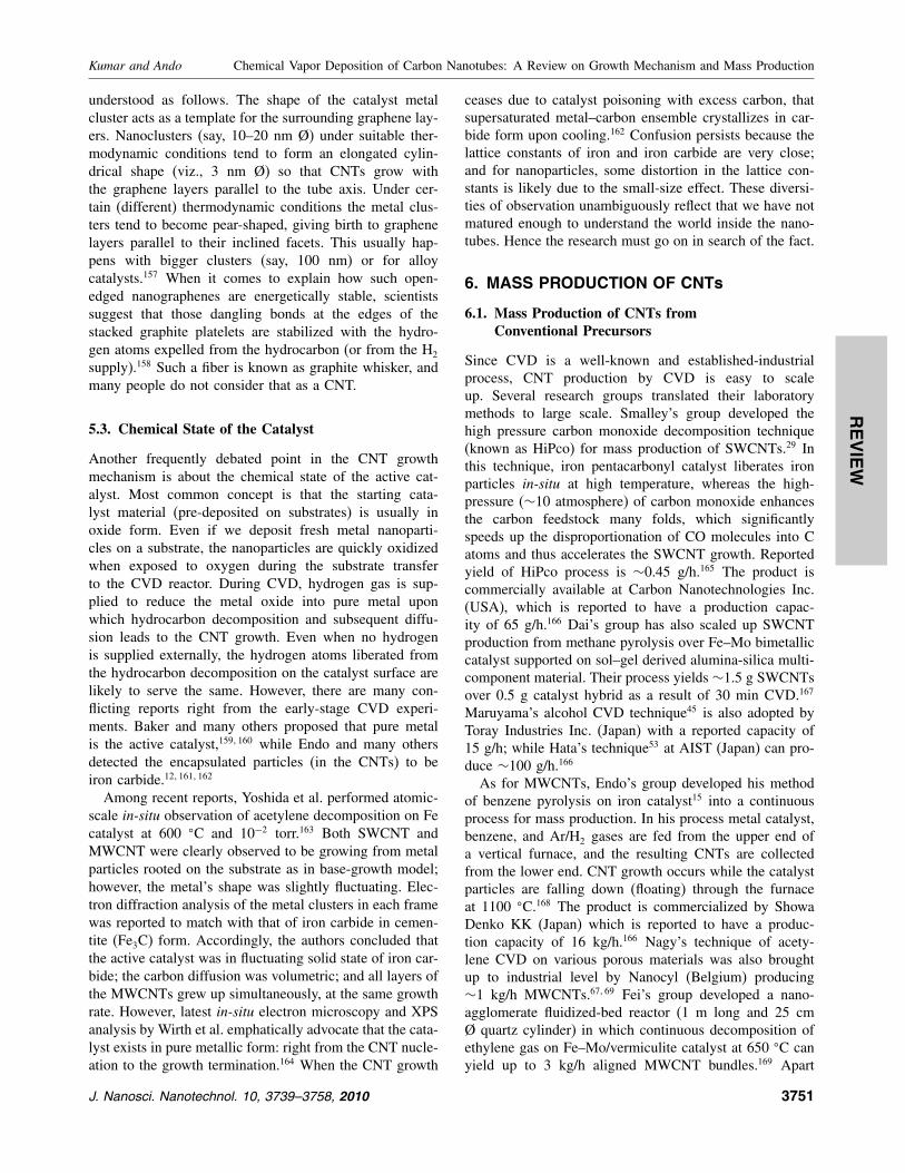
Quite intriguingly, however, two months after Hoff-
mann’s report,155 Terrones and Banhart group reported an
exciting observation of CNT formation in an HRTEM by
simply holding a metal-encapsulated MWCNT at 600 �Cunder electron beam (300 kV) for 90 min.156 Carbon atoms
(i) (ii) (iii)
Fig. 6. Schematic representation of the basic steps of SWCNT growth
on a Fe catalyst, as observed in ab initio simulations. (i) Diffusion of
single C atoms (red spheres) on the surface of the catalyst. (ii) Formation
of an sp2 graphene sheet floating on the catalyst surface with edge atoms
covalently bonded to the metal. (iii) Root incorporation of diffusing single
C atoms (or dimers). Reprinted with permission from [154], J. Y. Raty
et al., Phys. Rev. Lett. 95, 096103 (2005). © 2005, American Physical
Society.
(a)
(b)
(c)
Fig. 7. In-situ observation of CNT growth under HRTEM. (a) Electron
beam knocks some carbon atoms from the MWCNT side walls into the
encapsulated metal cluster. (b) The metal cluster reshapes its flat cross
section into a convex dome and a carbon cap appears over the dome.
(c) At the base of the metal dome, atomic steps develop and new MWC-
NTs emerge coaxial to the original MWCNT. [Courtesy: M. Terrones]
from the side walls (the existing graphite layers around
the encapsulated metal) got injected into the metal bulk
and emerged in the form of new SW, DW and MWC-
NTs of smaller diameters coaxial to the original MWCNT
(Fig. 7). Such a prolonged observation of the CNT-growth
dynamics (atom-by-atom) clearly evidences bulk diffu-
sion. Nevertheless, we should note that this observation
was an exclusive case of rearrangement of the carbon-iron
ensemble inside a constrained nanoreactor (the original
MWCNT) under high-energy electron-beam irradiation, a
situation far away from usual CVD conditions. Hence such
bulk diffusion cannot be conceptualized as a general CNT
growth mechanism.
In the context of the changing metal shape during
CVD, it is pertinent to mention another aspect of the
CNT growth. Many a time we encounter CNTs with their
graphene layers inclined to the tube axis (herringbone or
stacked-cup structure). It is puzzling to think how they
form. Keeping in mind that graphite layers grow prefer-
entially on selected crystal planes of metal, this can be
3750 J. Nanosci. Nanotechnol. 10, 3739–3758, 2010
REVIEW
Kumar and Ando Chemical Vapor Deposition of Carbon Nanotubes: A Review on Growth Mechanism and Mass Production
understood as follows. The shape of the catalyst metal
cluster acts as a template for the surrounding graphene lay-
ers. Nanoclusters (say, 10–20 nm Ø) under suitable ther-
modynamic conditions tend to form an elongated cylin-
drical shape (viz., 3 nm Ø) so that CNTs grow with
the graphene layers parallel to the tube axis. Under cer-
tain (different) thermodynamic conditions the metal clus-
ters tend to become pear-shaped, giving birth to graphene
layers parallel to their inclined facets. This usually hap-
pens with bigger clusters (say, 100 nm) or for alloy
catalysts.157 When it comes to explain how such open-
edged nanographenes are energetically stable, scientists
suggest that those dangling bonds at the edges of the
stacked graphite platelets are stabilized with the hydro-
gen atoms expelled from the hydrocarbon (or from the H2
supply).158 Such a fiber is known as graphite whisker, and
many people do not consider that as a CNT.
5.3. Chemical State of the Catalyst
Another frequently debated point in the CNT growth
mechanism is about the chemical state of the active cat-
alyst. Most common concept is that the starting cata-
lyst material (pre-deposited on substrates) is usually in
oxide form. Even if we deposit fresh metal nanoparti-
cles on a substrate, the nanoparticles are quickly oxidized
when exposed to oxygen during the substrate transfer
to the CVD reactor. During CVD, hydrogen gas is sup-
plied to reduce the metal oxide into pure metal upon
which hydrocarbon decomposition and subsequent diffu-
sion leads to the CNT growth. Even when no hydrogen
is supplied externally, the hydrogen atoms liberated from
the hydrocarbon decomposition on the catalyst surface are
likely to serve the same. However, there are many con-
flicting reports right from the early-stage CVD experi-
ments. Baker and many others proposed that pure metal
is the active catalyst,159�160 while Endo and many others
detected the encapsulated particles (in the CNTs) to be
iron carbide.12�161�162
Among recent reports, Yoshida et al. performed atomic-
scale in-situ observation of acetylene decomposition on Fe
catalyst at 600 �C and 10−2 torr.163 Both SWCNT and
MWCNT were clearly observed to be growing from metal
particles rooted on the substrate as in base-growth model;
however, the metal’s shape was slightly fluctuating. Elec-
tron diffraction analysis of the metal clusters in each frame
was reported to match with that of iron carbide in cemen-
tite (Fe3C) form. Accordingly, the authors concluded that
the active catalyst was in fluctuating solid state of iron car-
bide; the carbon diffusion was volumetric; and all layers of
the MWCNTs grew up simultaneously, at the same growth
rate. However, latest in-situ electron microscopy and XPS
analysis by Wirth et al. emphatically advocate that the cata-
lyst exists in pure metallic form: right from the CNT nucle-
ation to the growth termination.164 When the CNT growth
ceases due to catalyst poisoning with excess carbon, that
supersaturated metal–carbon ensemble crystallizes in car-
bide form upon cooling.162 Confusion persists because the
lattice constants of iron and iron carbide are very close;
and for nanoparticles, some distortion in the lattice con-
stants is likely due to the small-size effect. These diversi-
ties of observation unambiguously reflect that we have not
matured enough to understand the world inside the nano-
tubes. Hence the research must go on in search of the fact.
6. MASS PRODUCTION OF CNTs
6.1. Mass Production of CNTs fromConventional Precursors
Since CVD is a well-known and established-industrial
process, CNT production by CVD is easy to scale
up. Several research groups translated their laboratory
methods to large scale. Smalley’s group developed the
high pressure carbon monoxide decomposition technique
(known as HiPco) for mass production of SWCNTs.29 In
this technique, iron pentacarbonyl catalyst liberates iron
particles in-situ at high temperature, whereas the high-
pressure (∼10 atmosphere) of carbon monoxide enhances
the carbon feedstock many folds, which significantly
speeds up the disproportionation of CO molecules into C
atoms and thus accelerates the SWCNT growth. Reported
yield of HiPco process is ∼0.45 g/h.165 The product is
commercially available at Carbon Nanotechnologies Inc.
(USA), which is reported to have a production capac-
ity of 65 g/h.166 Dai’s group has also scaled up SWCNT
production from methane pyrolysis over Fe–Mo bimetallic
catalyst supported on sol–gel derived alumina-silica multi-
component material. Their process yields ∼1.5 g SWCNTs
over 0.5 g catalyst hybrid as a result of 30 min CVD.167
Maruyama’s alcohol CVD technique45 is also adopted by
Toray Industries Inc. (Japan) with a reported capacity of
15 g/h; while Hata’s technique53 at AIST (Japan) can pro-
duce ∼100 g/h.166
As for MWCNTs, Endo’s group developed his method
of benzene pyrolysis on iron catalyst15 into a continuous
process for mass production. In his process metal catalyst,
benzene, and Ar/H2 gases are fed from the upper end of
a vertical furnace, and the resulting CNTs are collected
from the lower end. CNT growth occurs while the catalyst
particles are falling down (floating) through the furnace
at 1100 �C.168 The product is commercialized by Showa
Denko KK (Japan) which is reported to have a produc-
tion capacity of 16 kg/h.166 Nagy’s technique of acety-
lene CVD on various porous materials was also brought
up to industrial level by Nanocyl (Belgium) producing
∼1 kg/h MWCNTs.67�69 Fei’s group developed a nano-
agglomerate fluidized-bed reactor (1 m long and 25 cm
Ø quartz cylinder) in which continuous decomposition of
ethylene gas on Fe–Mo/vermiculite catalyst at 650 �C can
yield up to 3 kg/h aligned MWCNT bundles.169 Apart
J. Nanosci. Nanotechnol. 10, 3739–3758, 2010 3751
REVIEW
Chemical Vapor Deposition of Carbon Nanotubes: A Review on Growth Mechanism and Mass Production Kumar and Ando
from these university-venture-business associates, many
other companies are also there in CNT business. To name
some, Hyperion Catalysis International, Inc. USA (8 kg/h),
Nano Carbon Technologies Co. Ltd. Japan (5 kg/h), Sun
Nanotech Co. Ltd. China (0.6 kg/h), Shenzhen Nano-
Technologies Port Co. Ltd. China (5 kg/h).166
As per WTEC survey report,166 the consolidated CNT
production capacity of the world today is∼300 tons MWC-
NTs and ∼7 tons SWCNTs per year, while their expected
demand would exceed 1000 tons/year in the near future.
The present price of commercially available MWCNTs is
∼$1/g, while that of SWCNTs is ∼$100/g. At this rate,
CNT-based products would be about 10 times costlier than
prevalent products. Hence the scientists and engineers have
a great responsibility to develop more cost-effective pro-
duction techniques to bring down the prices to $100/kg and
$10,000/kg for MWCNTs and SWCNTs respectively.
A good sign is that CVD-based CNT technique is pro-
gressing fast, and innumerous companies are emerging.
However, a common problem of mass-produced CNTs is
that their purity decreases with the increasing yield. CNT
properties are easy to control in small reactors, as used
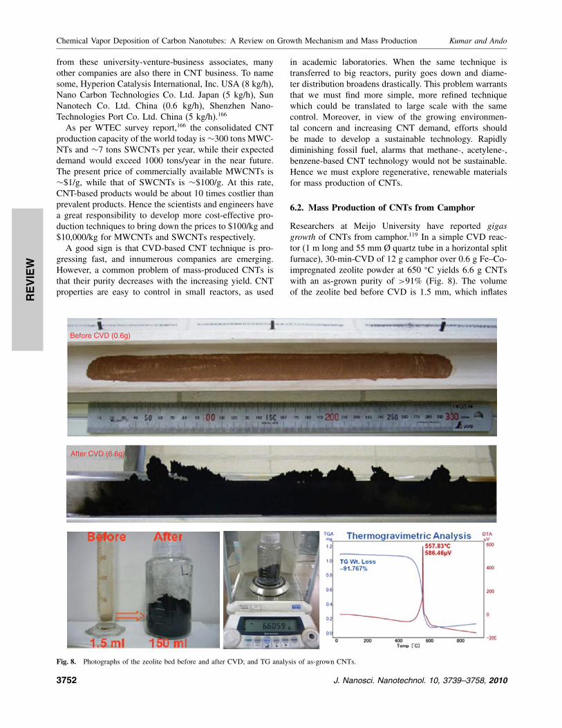
Before CVD (0.6g)
After CVD (6.6g)
Fig. 8. Photographs of the zeolite bed before and after CVD; and TG analysis of as-grown CNTs.
in academic laboratories. When the same technique is
transferred to big reactors, purity goes down and diame-
ter distribution broadens drastically. This problem warrants
that we must find more simple, more refined technique
which could be translated to large scale with the same
control. Moreover, in view of the growing environmen-
tal concern and increasing CNT demand, efforts should
be made to develop a sustainable technology. Rapidly
diminishing fossil fuel, alarms that methane-, acetylene-,
benzene-based CNT technology would not be sustainable.
Hence we must explore regenerative, renewable materials
for mass production of CNTs.
6.2. Mass Production of CNTs from Camphor
Researchers at Meijo University have reported gigasgrowth of CNTs from camphor.119 In a simple CVD reac-
tor (1 m long and 55 mm Ø quartz tube in a horizontal split
furnace), 30-min-CVD of 12 g camphor over 0.6 g Fe–Co-
impregnated zeolite powder at 650 �C yields 6.6 g CNTs
with an as-grown purity of >91% (Fig. 8). The volume
of the zeolite bed before CVD is 1.5 mm, which inflates
3752 J. Nanosci. Nanotechnol. 10, 3739–3758, 2010
REVIEW
Kumar and Ando Chemical Vapor Deposition of Carbon Nanotubes: A Review on Growth Mechanism and Mass Production
to 150 mm owing to a gigantic CNT growth (10,000%).
Hence the authors call it gigas growth. In this process,
camphor-to-CNT production efficiency is >50%, which is
much higher than that reported from any CNT precursor in
an academic laboratory set-up. Here it is to be noted that
the carbon content of camphor is approximately 79 wt%.
So, with respect to the carbon content in the feed stock,
net carbon-to-CNT conversion efficiency comes out to be
61 wt%. There are plenty of reports of large-scale CNT
synthesis; but most of them express the yield either on the
basis of TEM observation, or wait gain relative to the cata-
lyst. From industrial point of view, the product yield must
be quoted with respect to the raw material used. CNT lit-
erature largely lacks this figure of merit. To compare cam-
phor’s efficiency with that of other precursors, CVDs of a
few liquid precursors were carried out on the same set up,
in the same conditions. CVD of 12 g ethanol and benzene
yielded about 2 g and 3 g CNTs, respectively; much lower
than the camphor case (6 g). Here it is arguable that every
precursor has its own set of best conditions. Ethanol or
benzene cannot give their best yields at the condition opti-
mized for camphor. So, more systemic study is required
to compare different precursors. Recently, Montoro et al.
carried out a comparative study of several alcohols and
ketones as a CNT precursor over Mn–Co-impregnated zeo-
lite support at 600 �C.170 Acetone was found the best pre-
cursor (better that ethanol). This report is in agreement
with our experience that camphor (a member of ketone
family) stood the best. More recently, Musso et al. also
investigated thermal decompositions of camphor, cyclo-
hexanol and ethanol at 900 �C using ferrocene catalyst;
and found that camphor gave the highest CNT yield with
best crystallinity.171 On the other hand, Das et al. studied
the effect of feedstock and process conditions on CNT syn-
thesis from several aromatic hydrocarbons (unfortunately,
camphor was not there).172 They systematically calculated
the CNT yield with respect to the feedstock, and found
that carbon-to-CNT conversion efficiency ranged within
20–39%. On that scale, camphor scores very high (61%).
The high CNT-production efficiency of camphor
(C10H16O) may be attributed to several factors.
(i) Cage-like carbon structure offers ease of transforma-
tion into fullerene and CNTs.
(ii) Ring-based CNT-growth process is supposed to lead
to higher growth rate.
(iii) Carbon-rich precursors have shown higher CNT
yields.
(iv) Abundance of hydrogen and presence of oxygen in
camphor may have a good coordination in reducing metal
oxide and etching amorphous carbon.
However, more-elaborated experiments and theoretical
supports are required to establish these reasons. Enthusias-
tic researchers are encouraged to take up these challenges.
6.3. Camphor versus Conventional CNT Precursors
As compared to conventional CNT precursors such as
CH4, C2H4, C2H2, C6H6, camphor (C10H16O) is carbon-
rich, hydrogen-rich, and oxygen-present. It is thought that
the bi-cyclic cage-structure of camphor plays a vital role
in such an efficient CNT growth. Most probably, the
hexagonal and pentagonal carbon rings of camphor con-
struct CNTs as a basic building block: without break-
ing into atomic carbon. Researchers often use to mix a
small amount of hydrogen gas in the carrier gas to reduce
metal oxide into pure metal catalyst. Abundance of hydro-
gen in camphor serves this purpose to a great extent
and eliminates the need of additional hydrogen mixing
in the carrier gas. Moreover, the oxygen atom present in
camphor molecule helps oxidizing amorphous carbon in-situ, as proposed by Maruyama et al.45 Thus every atom
of camphor has a positive role towards CNT synthesis.
A probable growth mechanism of CNTs from camphor
was first reported in 2003.117 Later, a Chinese group car-
ried out in-situ mass spectroscopy of benzene CVD and
supported the ring-based CNT growth hypothesis.173 In
particular, low-temperature camphor CVD (650 �C) rulesout the possibility of spontaneous (uncatalyzed) decompo-
sition of camphor vapor in the reactor, and results in CNTs
free from amorphous carbon. There is no trace of carbon
deposit in any portion of the quartz tube except on the
zeolite bed.
6.4. Environment-Friendliness of Camphor CVD
The United States Environmental Protection Agency has
formulated 12 Principles of Green Chemistry that explain
what green chemistry means in actual practice.174 Waste
prevention, atom economy, energy efficiency and renew-
able feed stock are most vital points for an industrial
process to be environmentally benign. Using those prin-
ciples as a protocol, we can evaluate how environment-
friendly this technique is. It is straightforward that the
higher is the yield the lesser is the waste. Exhibiting high-
est CNT-production efficiency, camphor complies with the
waste-prevention rule significantly. Moreover, as explained
above, every atom of camphor plays a positive role in
CNT synthesis, which accounts for maximum carbon-to-
CNT conversion efficiency. This is a good example of
atom economy. Further, by virtue of a low-temperature and
atmospheric-pressure CVD process, the energy require-
ment of this technique is very low (as compared to high-
temperature low-pressure CVD-CNT processes). Hence
certainly it is an energy-efficient method. And last but not
the least, the main raw material—camphor—being an agri-
cultural product, is absolutely a regenerative feedstock; so
there is no danger of depleting a natural resource. Thus,
camphor-based CNT synthesis technique complies with
the principles of green chemistry to a great extent. This
work has attracted the attention of industrial ecologists.175
J. Nanosci. Nanotechnol. 10, 3739–3758, 2010 3753

REVIEW
Chemical Vapor Deposition of Carbon Nanotubes: A Review on Growth Mechanism and Mass Production Kumar and Ando
6.5. Industrial Production of CNTs from Camphor
Camphor CVD has been successfully scaled up to industrial
production of MWCNTs at Meijo Nano Carbon Co. Ltd.,
Japan. A big quartz tube (2 m long and 0.25 m Ø) installed
in an especially-designed rotary kiln (Takasago Co. Ltd.,
Japan) is used as a CVD reactor. Camphor and catalyst-
loaded zeolite powder are simultaneously fed in the reac-
tor from the left and right ends, respectively, through
two speed-controllable feeders. The quartz tube is slightly
inclined and keeps on rotating about its axis, so that the
zeolite powder falling on the right end of hot zone slides
down the slope; and by the time it reaches the left end of
the hot zone, CNTs would have efficiently grown onto it.
As-grown CNTs safely fall down into a reservoir at the
left end. The system can run continuously for hours. Aav-
erage production rate is about 1 kg/h and the purity of
as-grown MWCNTs is about 90%. Due to extremely low
price of camphor ($10/kg), the expected production cost of
as-grown CNTs is very low ($100/kg).
7. EXISTING CHALLENGES ANDFUTURE DIRECTIONS
In the foregoing sections, we raised several questions on
the role of precursor, catalyst, catalyst support, growth
mechanism and mass production, and indicated possible
directions. In addition to those basic issues, other growth-
related challenges are briefly outlined below.
1. Researchers have succeeded in minimizing the diameter
distribution of SWCNTs up to some extent.176 However,
synthesis of SWCNTs of a given diameter is yet to be
achieved.177 It would be possible only when we have the
catalyst particles all of exactly the same diameter (say,
0.5 nm).
2. Chirality control is even more challenging. Re-growth
from ordered arrays of open-ended SWCNTs may help
up to some extent.178 Alternatively, we have to develop
proper separation methods that could first sort out CNTs
according to metallic or semiconducting tubes and then
select tubes of certain chirality.
3. In MWCNTs, control on the number of walls is another
big challenge. Synthesis of thin MWCNTs (3–6 walls) is
a better choice than thick MWCNTs.179�180
4. Growth of isolated CNTs has not yet reached a mature
stage. There are indications that even a single CNT does
not possess the same diameter and chirality over the entire
length. How can we solve it?
5. Researchers have succeeded in growing CNTs from
almost all metals.181 However, we do not know how differ-
ent metals affect physical, chemical, electronic and optical
and magnetic properties of as-grown CNTs. If we could
discover any correlation between the type of the metal
used and the property of the CNT grown, we would be
able to grow CNTs of selective properties.
6. What is/are the determining steps in CNT nucleation
and growth? Having known these steps, the CNT growth
rate could be increased for mass production.182
7. The exact role of H2, O2 and H2O in CNT growth is
yet to be clarified.183 Simultaneous presence of reducing
as well as oxidizing agents in the reaction zone makes it
ambiguous whether amorphous carbon is etched by atomic
hydrogen, oxygen or water. Are they really essential?54
8. Researchers have succeeded in bringing down the CNT
growth temperature to ∼400 �C in low-pressure CVD.184
However, low-pressure CVD greatly reduces the growth
rate and yield. Low-temperature CNT growth must be
devised at atmospheric pressure for high yields of CNTs.
9. Many technological applications are looking for room-
temperature CNT growth which is still a dream, so far as
thermal CVD is concerned.
10. Mass-produced CNTs usually contain catalyst par-
ticles or support materials as impurity. Post-deposition
purification greatly reduces the CNT quality and final out-
put. More thoughts should be given to achieve high-purity
in as-grown state.
11. CVD-grown CNTs (especially low-temperature
MWCNTs) have poor crystallinity. With a suitable com-
bination of different catalysts, it should be possible to get
better-crystallinity CNTs.
12. Recent metal-free oxygen-assisted CNT growth is a
breakthrough.99–101 It must be scaled up to mass produc-
tion of high-purity CNTs.
13. Carbon–metal phase diagram needs to be recon-
structed, especially for 1–5 nm range relevant to CNT
growth.185
14. All extraordinary properties of CNTs are predicted for
atomically-perfect CNTs. To make those predictions true,
it is of prime importance to develop new techniques to
monitor and remove defects in-situ.15. Lack of quality control and assessment of CNTs syn-
thesized by different groups by different methods does not
allow us to get correct product details. Analytical sampling
of CNTs obtained from different sources at an authorized
standard laboratory would reveal exact merits and demer-
its of different techniques, which would in turn help us
explore combinations of techniques toward higher-yield,
higher-purity and lower-cost mass production.
What we have mentioned above are only growth-related
challenges. There are many application-related challenges
whose mention is beyond the scope of this review.
8. CONCLUDING REMARKS
In 2000 Rick Smalley said about CNTs, “Buckytubes are
in high school now.” After 10 years of his statement, we
feel that CNTs are now in university; they have not yet
graduated and joined their jobs out. As we have seen in
the foregoing sections, despite great progresses over the
years, there are many basic issues concerning the CNT
3754 J. Nanosci. Nanotechnol. 10, 3739–3758, 2010
REVIEW
Kumar and Ando Chemical Vapor Deposition of Carbon Nanotubes: A Review on Growth Mechanism and Mass Production
growth mechanism which are still not clear. Contradictory
observations of CNT growth under electron microscopy by
different groups suggest that the mechanism is extremely
sensitive to each parameter such as carbon precursor, metal
catalyst, particle size, temperature, pressure. Even a minor
change in any of these parameters leads the growth in crit-
ically different directions. Catalysis is the main stem of
CVD-CNT technique; and it seems that we have not yet
utilised the best of catalysis in this field. Nano-catalystmaterials are needed to be developed and investigated in
more detail. In principle, with the use of a suitable cata-
lyst, the CVD temperature can be brought down to room
temperature. By identifying the growth-limiting steps it
should be possible to control the diameter and chirality
of the resulting CNTs. To comply with the environmental
concerns, renewable materials should be explored as CNT
precursors. In view of the expected giant demand of CNTs
in the near future, industrial production of CNTs should
be carried out with far-sighted thoughts for long-term sus-
tainability. Fossil-fuel based CNT-production technology
would not be sustainable. The unanswered questions about
growth mechanism and the existing challenges concerning
the growth control will keep the CNT researchers engaged
for a long time. In quest for knowledge, in pursuit of per-
fection, and for contributing to science and society, the
CNT research must go on.
Acknowledgments: This work was financially sup-
ported by the Japan Society for the Promotion of Science
(Grants-in-aid for Scientific Research), the Ministry of
Economy Trade and Industry (Regional Resources R&D),
and the Ministry of Education, Culture, Sports, Science
and Technology (Regional Innovation Creation R&D).
The authors are grateful to Dr. Toshio Kurauchi (For-
mer Vice President, Toyota Central R&D Labs Inc.),
Mr. Takeshi Hashimoto (President, Meijo Nano Carbon
Co. Ltd.), Mr. Akira Kagohashi (Managing Director,
Takasago Industry Co. Ltd.) and Mr. Hirotaka Masuoka
(Director, Masuoka Ceramic Materials Co. Ltd.), whose
joint efforts drove our work from laboratory to industry.
Mukul Kumar thanks Dr. Debabrata Pradhan for his great
help on the references.
References and Notes
1. L. V. Radushkevich and V. M. Lukyanovich, Zh. Fizich. Khim. (inRussian) 26, 88 (1952).
2. P. A. Tesner and A. I. Echeistova, Doklady Akad. Nauk USSR87, 1029 (1952).
3. W. R. Davis, R. J. Slawson, and G. R. Rigby, Nature 171, 756
(1953).4. L. J. E. Hofer, E. Sterling, and J. T. McCartney, J. Phys. Chem.
59, 1153 (1955).5. P. L. Walker, J. F. Rakszawski, and G. R. Imperial, J. Phys. Chem.
63, 133 (1959).6. T. Baird, J. R. Fryer, and B. Grant, Nature 233, 329 (1971).7. T. Baird, J. R. Fryer, and B. Grant, Carbon 12, 591 (1974).
8. R. T. K. Baker, M. A. Barber, P. S. Harris, F. S. Feates, and R. J.
Waite, J. Catalysis 26, 51 (1972).9. R. T. K. Baker, P. S. Harris, R. B. Thomas, and R. J. Waite,
J. Catalysis 30, 86 (1973).10. R.T. K. Baker and R. J. Waite, J. Catalysis 37, 101 (1975).11. T. Koyama, M. Endo, and Y. Onuma, Jpn. J. Appl. Phys. 11, 445
(1972).12. A. Oberlin, M. Endo, and T. Koyama, J. Cryst. Growth 32, 335
(1976).13. R. T. K. Baker and P. S. Harris, Chemistry and Physics of Carbon,
edited by P. L. Walker and P. A. Thrower, Marcel Dekker, NY
(1978), Vol. 14, p. 83.14. R. T. K. Baker, Carbon 27, 315 (1989).15. M. Endo, Chemtech 18, 568 (1988).16. M. S. Dresselhaus, G. Dresselhaus, K. Sugihara, I. L. Spain, and
H. A. Goldberg, Graphite Fibers and Filaments, Springer-Verlag,
Berlin (1988).17. J. S. Speck, M. Endo, and M. S. Dresselhaus, J. Cryst. Growth
94, 834 (1989).18. S. Iijima, Nature 354, 56 (1991).19. P. Schultzenberger and L. Schultzenberger, C.R. Acad. Sci. Paris
111, 774 (1890).20. M. Endo, K. Takeuchi, K. Kobori, K. Takahashi, H. W. Kroto, and
A. Sarkar, Carbon 33, 873 (1995).21. S. B. Sinnott, R. Andrews, D. Qian, A. M. Rao, Z. Mao, E. C.
Dickey, and F. Derbyshire, Chem. Phys. Lett. 315, 25 (1999).22. K. Hernadi, A. Fonseca, J. B. Nagy, D. Bernaerts, and A. A. Lucas,
Carbon 34, 1249 (1996).23. J. Kong, A. M. Cassell, and H. Dai, Chem. Phys. Lett. 292, 567
(1998).24. S. Fan, M. Chapline, N. Frankline, T. Tombler, A. M. Cassel, and
H. Dai, Science 283, 512 (1999).25. B. C. Satiskumar, A. Govindaraj, and C. N. R. Rao, Chem. Phys.
Lett. 307, 158 (1999).26. W. Z. Li, S. Xie, L. X. Qian, B. H. Chang, B. S. Zou, W. Y. Zhou,
R. A. Zhao, and G. Wang, Science 274, 1701 (1996).27. R. Sen, A. Govindaraj, and C. N. R. Rao, Chem. Phys. Lett.
267, 276 (1997).28. B. Q. Wei, R. Vajtai, Y. Jung, J. Ward, R. Zhang, G. Ramanath,
and P. M. Ajayan, Nature 416, 495 (2002).29. P. Nikolaev, M. J. Bronikowski, R. K. Bradley, F. Rohmund, D. T.
Colbert, K. A. Smith, and R. E. Smalley, Chem. Phys. Lett. 313, 91(1999).
30. M. Endo, H. Fijiwara, and E. Fukunaga, 18th Meeting JapaneseCarbon Society, Japanese Carbon Society, Saitama, December
(1991), p. 34.31. M. Endo, K. Takeuchi, S. Igarashi, K. Kobori, M. Shiraishi, and
H. W. Kroto, 19th Meeting Japanese Carbon Society, Japanese Car-bon Society, Kyoto, December (1992), p. 192.
32. M. Endo, K. Takeuchi, S. Igarashi, K. Kobori, M. Shiraishi, and
H. W. Kroto, J. Phys. Chem. Solids 54, 1841 (1993).33. M. Jose-Yacaman, M. Miki-Yoshida, L. Rendon, and J. G.
Santiesteban, Appl. Phys. Lett. 62, 657 (1993).34. Z. Liua, R. Cheb, Z. Xu, and L. Peng, Synth. Met. 128, 191 (2002).35. N. Li, X. Chen, L. Stoica, W. Xia, J. Qian, J. Abmann,
W. Schuhmann, and M. Muhler, Adv. Mater. 19, 2957 (2007).36. O. A. Nerushev, S. Dittmar, R. E. Morjan, F. Rohmund, and E. E.
B. Campbell, J. Appl. Phys. 93, 4185 (2003).37. R. E. Morjan, O. A. Nerushev, M. Sveningsson, F. Rohmund, L. K.
L. Falk, and E. E. B. Campbell, Appl. Phys. A 78, 253 (2004).38. H. Dai, A. G. Rinzler, P. Nikolaev, A. Thess, D. T. Colbert, and
R. E. Smalley, Chem. Phys. Lett. 260, 471 (1996).39. H. M. Cheng, F. Li, X. Sun, S. D. M. Brown, M. A. Pimenta,
A. Marucci, G. Dresselhaus, and M. S. Dresselhaus, Chem. Phys.Lett. 289, 602 (1998).
40. B. C. Satishkumar, A. Govindaraj, R. Sen, and C. N. R. Rao, Chem.Phys. Lett. 293, 47 (1998).
J. Nanosci. Nanotechnol. 10, 3739–3758, 2010 3755
REVIEW
Chemical Vapor Deposition of Carbon Nanotubes: A Review on Growth Mechanism and Mass Production Kumar and Ando
41. J. H. Hafner, M. J. Bronikowski, B. R. Azamian, P. Nikolaev, A. G.
Rinzler, D. T. Colbert, K. A. Smith, and R. E. Smalley, Chem.Phys. Lett. 296, 195 (1998).
42. E. Flahaut, A. Govindaraj, A. Peigney, C. Laurent, and C. N. R.
Rao, Chem. Phys. Lett. 300, 236 (1999).43. A. Gruneis, M. H. Rummeli, C. Kramberger, D. Grimm,
T. Gemming, A. Barreiro, P. Ayala, T. Pichler, H. Kuzmany,
C. Schamann, R. Pfeiffer, J. Schumann, and B. Büchner, PhysicaStatus Solidi B 243, 3054 (2006).
44. S. Maruyama, Y. Miyauchi, T. Edamura, Y. Igarashi, S. Chiashi,
and Y. Murakami, Chem. Phys. Lett. 375, 553 (2003).45. S. Maruyama, R. Kojima, Y. Miyauchi, S. Chiashi, and M. Kohno,
Chem. Phys. Lett. 360, 229 (2002).46. S. Okubo, T. Sekine, S. Suzuki, Y. Achiba, K. Tsukagoshi,
Y. Aoyagi, and H. Kataura, Jpn. J. Appl. Phys. 43, L396 (2004).47. A. Gruneis, M. H. Rummeli, C. Kramberger, A. Barreiro, T. Pichler,
R. Pfeiffer, H. Kuzmany, T. Gemming, and B. Buchner, Carbon44, 3177 (2006).
48. A. G. Nasibulin, A. Moisala, H. Jiang, and E. I. Kauppinen,
J. Nanopart. Res. 8, 465 (2006).49. Y. Murakami, Y. Miyauchi, S. Chiashi, and S. Maruyama, Chem.
Phys. Lett. 377, 49 (2003).50. Y. Murakami, S. Chiashi, Y. Miyauchi, M. Hu, M. Ogura, T. Okubo,
and S. Maruyama, Chem. Phys. Lett. 385, 298 (2004).51. S. Maruyama, E. Einarsson, Y. Murakami, and T. Edamura, Chem.
Phys. Lett. 403, 320 (2005).52. R. Xiang, E. Einarsson, J. Okawa, Y. Miyauchi, and S. Maruyama,
J. Phys. Chem. C 113, 7511 (2009).53. K. Hata, D. N. Futaba, K. Mizuno, T. Namai, M. Yumura, and
S. Iijima, Science 306, 1362 (2004).54. G. Zhong, S. Hofmann, F. Yan, H. Telg, J. H. Warner, D. Eder,
C. Thomsen, W. I. Milne, and J. Robertson, J. Phys. Chem. C113, 17321 (2009).
55. F. Ding, P. Larsson, J. A. Larsson, R. Ahuja, H. Duan, A. Rosen,
and K. Bolton, Nano Lett. 8, 463 (2008).56. H. Ago, T. Komatsu, S. Ohshima, Y. Kuriki, and M. Yumura, Appl.
Phys. Lett. 77, 79 (2000).57. A. Moisala, A. G. Nasibulin, and E. I. Kauppinen, J. Phys. Con-
dens. Mater. 15, S3011 (2003).58. R. Andrews, D. Jacques, A. M. Rao, F. Derbyshire, D. Qian, X.
Fan, E. C. Dickey, and J. Chen, Chem. Phys. Lett. 303, 467 (1999).59. M. Kumar and Y. Ando, Chem. Phys. Lett. 374, 521 (2003).60. M. Kumar, K. Kakamu, T. Okazaki, and Y. Ando, Chem. Phys.
Lett. 385, 161 (2004).61. D. Ding, J. Wang, Z. Cao, and J. Dai, Carbon 41, 579 (2003).62. T. Murakami, T. Sako, H. Harima, K. Kisoda, K. Mitikami, and
T. Isshiki, Thin Solid Films 464, 319 (2004).63. B. Kitiyanan, W. E. Alvarez, J. H. Harwell, and D. E. Resasco,
Chem. Phys. Lett. 317, 497 (2000).64. C. Mattevi, C. T. Wirth, S. Hofmann, R Blume, M. Cantoro,
C. Ducati, C. Cepek, A. Knop-Gericke, S. Milne, C. Castellarin-
Cudia, S. Dolafi, A. Goldoni, R. Schloegl, and J. Robertson,
J. Phys. Chem. C 112, 12207 (2008).65. C. L. Cheung, A. Kurtz, H. Park, and C. M. Lieber, J. Phys.
Chem. B 106, 2429 (2002).66. H. Hongo, M. Yudasaka, T. Ichihashi, F. Nihey, and S. Iijima,
Chem. Phys. Lett. 361, 349 (2002).67. I. Willems, Z. Konya, J. F. Colomer, G. V. Tendeloo, N. Nagaraju,
A. Fonseca, and J. B. Nagy, Chem. Phys. Lett. 317, 71 (2000).68. M. Kumar and Y. Ando, Carbon 43, 533 (2005).69. E. Couteau, K. Hernadi, J. W. Seo, L. T. Nga, C. Miko, R. Gaal,
and L. Forro, Chem. Phys. Lett. 378, 9 (2003).70. J. F. Colomer, C. Stephan, S. Lefrant, G. Van-Tendeloo, I. Willems,
Z. Konya, A. Fonseca, C. Laurent, and J. B. Nagy, Chem. Phys.Lett. 317, 83 (2000).
71. J. Ward, B. Q. Wei, and P. M. Ajayan, Chem. Phys. Lett. 376, 717(2003).
72. H. Ago, K. Nakamura, S. Imamura, and M. Tsuji, Chem. Phys.Lett. 391, 308 (2004).
73. K. Hernadi, A. Fonseca, J. B. Nagy, D. Bernaerts, A. Fudala, and
A. A. Lucas, Zeolites 17, 416 (1996).74. N. Nagaraju, A. Fonseca, Z. Konya, and J. B. Nagy, J. Mol. Catal. A
181, 57 (2002).75. H. Ago, K. Nakamura, N. Uehara, and M. Tsuji, J. Phys. Chem. B
108, 18908 (2004).76. C. L. Pint, S. T. Pheasant, M. Pasquali, K. E. Coulter, H. K.
Schmidt, and R. H. Hauge, Nano Lett. 8, 1879 (2008).77. S. Noda, K. Hasegawa, H. Sugime, K. Kakehi, Z. Zhang,
S. Maruyama, and Y. Yamaguchi, Jpn. J. Appl. Phys. 46, L399(2007).
78. D. Yuan, L. Ding, H. Chu, Y. Feng, T. P. McNicholas, and J. Liu,
Nano Lett. 8, 2576 (2008).79. D. Takagi, Y. Homma, H. Hibino, S. Suzuki, and Y. Kobayashi,
Nano Lett. 6, 2642 (2006).80. S. Bhaviripudi, E. Mile, S. A. Steiner, A. T. Zare, M. S.
Dresselhaus, A. M. Belcher, and J. Kong, J. Am. Chem. Soc.129, 1516 (2007).
81. D. Takagi, Y. Kobayashi, H. Hibino, S. Suzuki, and Y. Homma,
Nano Lett. 8, 832 (2008).82. R. L. Vander Wal, T. M. Ticich, and V. E. Curtis, Carbon 39, 2277
(2001).83. W. Deng, X. Xu, and W. A. Goddard, Nano Lett. 4, 2331 (2004).84. X. Tao, X. Zhang, J. Cheng, Y. Wang, F. Liu, and Z. Luo, Chem.
Phys. Lett. 409, 89 (2005).85. C. P. Deck and K. Vecchio, Carbon 44, 267 (2006).86. W. Zhou, Z. Han, J. Wang, Y. Zhang, Z. Jin, X. Sun, Y. Zhang,
C. Yan, and Y. Li, Nano Lett. 6, 2987 (2006).87. X. Sun, Y. Zhang, R. Si, and C. Yan, Small 1, 1081 (2005).88. M. Ritschel, A. Leonhardt, D. Elefant, S. Oswald, and B. Buchner,
J. Phy. Chem. C 111, 8414 (2007).89. D. Takagi, Y. Kobayashi, and Y. Homma, J. Am. Chem. Soc.
131, 6922 (2009).90. M. H. Rummeli, E. Borowiak-Palen, T. Gemming, T. Pichler,
M. Knupfer, M. Kalbac, L. Dunsch, O. Jost, S. R. P. Silva,
W. Pompe, and B. Buchner, Nano Lett. 5, 1209 (2005).91. S. Han, X. Liu, and C. Zhou, J. Am. Chem. Soc. 127, 5294 (2005).92. D. Takagi, H. Hibino, S. Suzuki, Y. Kobayashi, and Y. Homma,
Nano Lett. 7, 2272 (2007).93. M. Kusunoki, T. Suzuki, T. Hirayama, and N. Shibata, Appl. Phys.
Lett. 77, 531 (2000).94. E. J. Bae, W. B. Choi, K. S. Jeong, J. U. Chu, G. S. Park, S. Song,
and Y. U. Yoo, Adv. Mater. 14, 277 (2002).95. J. J. Schneider, N. I. Maksimova, J. Engstler, R. Joshi,
R. Schierholz, and R. Feile, Inorg. Chim. Acta 361, 1770 (2008).96. W. Merchan-Merchan, A. Savaliev, L. A. Kennedy, and A. Fridman,
Chem. Phys. Lett. 354, 20 (2002).97. M. H. Rummeli, C. Kramberger, A. Gruneis, P. Ayala, T. Gemming,
B. Buchner, and T. Pichler, Chem. Mater. 19, 4105 (2007).98. M. H. Rummeli, F. Schaffel, C. Kramberger, T. Gemming,
A. Bachmatiuk, R. J. Kalenczuk, B. Rellinghaus, B. Buchner, and
T. Pichler, J. Am. Chem. Soc. 129, 15772 (2007).99. B. Liu, W. Ren, L. Gao, S. Li, S. Pei, C. Liu, C. Jiang, and H. M.
Cheng, J. Am. Chem. Soc. 131, 2082 (2009).100. H. Liu, D. Takagi, S. Chiashi, and Y. Homma, Carbon 48, 114
(2010).101. S. Huang, Q. Cai, J. Chen, Y. Qian, and L. Zhang, J. Am. Chem.
Soc. 131, 2094 (2009).102. S. Reich, L. Li, and J. Robertson, Chem. Phys. Lett. 421, 469
(2006).103. R. V. Parthasarathy, K. L. N. Phani, and C. R. Martin, Adv. Mater.
7, 896 (1995).104. T. Kyotani, L. F. Tsai, and A. Tomita, Chem. Mater. 8, 2109 (1996).105. C. Y. Han, Z. L. Xiao, H. H. Wang, X. M. Lin, S. Trasobares, and
R. E. Cook, J. Nanomater. 2009, 562376 (2009).
3756 J. Nanosci. Nanotechnol. 10, 3739–3758, 2010
REVIEW
Kumar and Ando Chemical Vapor Deposition of Carbon Nanotubes: A Review on Growth Mechanism and Mass Production
106. M. Sankaran and B. Viswanathan, Indian J. Chem. 47A, 808
(2008).107. Z. K. Tang, H. D. Sun, J. Wang, J. Chen, and G. Li, Appl. Phys.
Lett. 73, 2287 (1998).108. J. Zhai, Z. Tang, P. Sheng, and X. Hu, IEEE 2006, ICONN, IEEE,
Brisbane, July (2006), p. 155.109. M. Terrones, N. Grobert, J. Olivares, J. P. Zhang, H. Terrones,
K. Kordatos, W. K. Hsu, J. P. Hare, P. D. Townsend, K. Prassides,
A. K. Cheetham, H. W. Kroto, and D. R. M. Walton, Nature 388, 52(1997).
110. M. Yudasaka, R. Kikuchi, Y. Ohki, and S. Yoshimura, Carbon35, 195 (1997).
111. B. C. Satishkumar, P. J. Thomas, A. Govindaraj, and C. N. R. Rao,
Appl. Phys. Lett. 77, 2530 (2000).112. F. L. Deepak, A. Govindaraj, and C. N. R. Rao, Chem. Phys. Lett.
345, 5 (2001).113. G. Kucukayan, S. Kayacan, B. Baykal, and E. Bengu, Mater. Res.
Soc. Symp. Proc. (Symposium-P) 1081E, P05 (2008).114. M. Kumar, X. Zhao, and Y. Ando, International Symposium
on Nanocarbons, Nagano, Japan, Extended Abstract, November
(2001), pp. 244–245.115. M. Kumar, X. Zhao, Y. Ando, S. Iijima, M. Sharon, and
K. Hirahara, Mol. Cryst. Liq. Cryst. 387, 117 (2002).116. M. Kumar and Y. Ando, Diamond Related Mater. 12, 998 (2003).117. M. Kumar and Y. Ando, Diamond Related Mater. 12, 1845 (2003).118. M. Kumar, T. Okazaki, M. Hiramatsu, and Y. Ando, Carbon
45, 1899 (2007).119. M. Kumar and Y. Ando, Defence Sci. Journal 58, 496 (2008).120. M. Sharon, W. K. Hsu, H. W. Kroto, D. R. M. Walton,
A. Kawahara, T. Ishihara, and Y. Takita, J. Power Sources 104, 148(2002).
121. R. J. Andrews, C. F. Smith, and A. J. Alexander, Carbon 44, 341
(2006).122. K. Yamada, K. Abe, M. Mikami, M. Saito, and J. Kuwano,
Key Engg. Mater. 320, 163 (2006).123. S. P. Somani, P. R. Somani, A. Yoshida, M. Tanemura, S. P. Lau,
and M. Umeno, Solid-State Electron. 52, 1015 (2008).124. S. P. Somani, P. R. Somani, M. Tanemura, S. P. Lau, and
M. Umeno, Current Appl. Phys. 9, 144 (2009).125. H. Parshotam, M. Tech. Thesis, Chem. Dept., University of Johan-
nesburg (2008).126. E. F. Antunes, E. C. Almeida, C. B. F. Rosa, L. I. de Medeiros,
L. C. Pardini, M. Massi, and E. J. Corat, J. Nanosci. Nanotechnol.10 (2010), doi:10.1166/jnn.2010.1830, in press.
127. J. Tang, G. Jin, Y. Wang, and X Guo, Carbon 48, 1545 (2010).128. S. Musso, G. Fanchini, and A. Tagliaferro, Diamond Related Mater.
14, 784 (2005).129. S. Porro, S. Musso, M. Giorcelli, A. Tagliaferro, S. H. Dalal,
K. B. K. Teo, D. A. Jefferson, and W. I. Milne, J. Non-Cryst. Solids352, 1310 (2006).
130. S. Musso, S. Porro, M. Giorcelli, M. Giorrcelli, A. Chiodoni, A. C.
Ricciardi, and A. Tagliaferro, Carbon 45, 1133 (2007).131. S. Musso, S. Porro, M. Rovere, M. Giorcelli, and A. Tagliaferro,
J. Cryst. Growth 310, 477 (2008).132. M. Pavese, S. Musso, S. Bianco, M. Giorcelli, and N. Pugno,
J. Phys. Condens. Matter. 20, 474206 (2008).133. S. Bianco, M. Giorcelli, S. Musso, M. Castellino, F. Agresti,
A. Khandelwal, S. L. Russo, M. Kumar, and Y. Ando, J. Nanosci.Nanotechnol. 9, 6806 (2009).
134. M. Sharon and M. Sharon, Synth. React. Inorg. Met.-Org. Nano-Metal. Chem. 36, 265 (2006).
135. A. K. Chatterjee, M. Sharon, R. Banerjee, and M. Neumann-
Spallart, Electrochim. Acta 48, 3439 (2003).136. R. A. Afre, T. Soga, T. Jimbo, M. Kumar, Y. Ando, and M. Sharon,
Chem. Phys. Lett. 414, 6 (2005).
137. R. A. Afre, T. Soga, T. Jimbo, M. Kumar, Y. Ando, M. Sharon, P. R.
Somani, and M. Umeno, Microporous Mesoporous Mater. 96, 184(2006).
138. P. Ghosh, T. Soga, M. Tanemura, M. Zamri, T. Jimbo, R. Katoh,
and K. Sumiyama, Appl. Phys. A 94, 51 (2009).139. D. Pradhan and M. Sharon, Mater. Sci. Engg. B 96, 24 (2002).140. J. Qiu, Q. Li, Z. Wang, Y. Sun, and H. Zhang, Carbon 44, 2565
(2006).141. W. Qian, H. Yu, F. Wei, Q. Zhang, and Z. Wang, Carbon 40, 2968
(2002).142. Z. Kang, E. Wang, B. Mao, Z. Su, L. Chen, and L. Xu, Nanotech-
nology 16, 1192 (2005).143. W. Z. Li, J. G. Wen, and Z. F. Ren, Appl. Phys. A 74, 397 (2002).144. W. Z. Li, J. G. Wen, Y. Tu, and Z. F. Ren. Appl. Phys. A 73, 259
(2001).145. S. Maruyama, Y. Murakami, Y. Shibata, Y. Miyauchi, and
S. Chiashi, J. Nanosci. Nanotechnol. 4, 360 (2004).146. J. Li, C. Papadopoulos, J. M. Xu, and M. Moskovits, Appl. Phys.
Lett. 75, 367 (1999).147. C. Bower, O. Zhou, W. Zhu, D. J. Werder, and S. Jin, Appl. Phys.
Lett. 77, 2767 (2000).148. G. G. Tibbetts, J. Cryst. Growth 66, 632 (1984).149. R. S. Wagner and W. C. Ellis, Trans. Metallurg. Soc. AIME
233, 1053 (1965).150. F. Ding, K. Bolton, and A. Rosen, J. Chem. Phys. B 108, 17369
(2004).151. A. R. Harutyunyan and T. Tokune, Appl. Phys. Lett. 87, 051919
(2005).152. F. Ding, K. Bolton, and A. Rosen, Comput. Mater. Sci. 35, 243
(2006).153. S. Helveg, C. Lopez-Cartes, J. Sehested, P. L. Hansen, B. S.
Clausen, J. R. Rostrup-Nielsen, F. Abild-Pedersen, and J. K.
Nørskov, Nature 427, 426 (2004).154. J. Y. Raty, F. Gygi, and G. Galli, Phys. Rev. Lett. 95, 096103 (2005).155. S. Hofmann, R. Sharma, C. Ducati, G. Du, C. Mattevi, C. Cepek,
M. Cantoro, S. Pisana, A. Parvez, F. Cervantes-Sodi, A. C. Ferrari,
R. Dunin-Borkowski, S. Lizzit, L. Petaccia, A. Goldoni, and
J. Robertson, Nano Lett. 7, 602 (2007).156. J. A. Rodriguez-Manzo, M. Terrones, H. Terrones, H. W. Kroto,
L. Sun, and F. Banhart, Nat. Nanotechnol. 2, 307 (2007).157. M. S. Kim, N. M. Rodriguez, and R. T. K. Baker, J. Catal. 134, 253
(1992).158. P. E. Nolan, D. C. Lynch, and A. H. Cutler, J. Phys. Chem. B
102, 4165 (1998).159. R. T. K. Baker, J. R. Alonzo, J. A. Dumesic, and D. J. C. Yates,
J. Catal. 77, 74 (1982).160. K. L. Yang and R. T. Yang, Carbon 24, 687 (1986).161. M. Audier, P. Bowen, and W. Jones, J. Cryst. Growth 64, 291
(1983).162. C. Ducati, I. Alexandrou, M. Chhowalla, J. Robertson, and G. A.
J. Amaratunga, J. Appl. Phys. 95, 6387 (2004).163. H. Yoshida, S. Takeda, T. Uchiyama, H. Kohno, and Y. Homma,
Nano Lett. 8, 2082 (2008).164. C. T. Wirth, S. Hofmann, and J. Robertson, Diamond Related
Mater. 18, 940 (2009).165. M. J. Bronikowski, P. A. Willis, D. T. Colbert, K. A. Smith, and
R. E. Smalley, J. Vac. Sci. Technol. A 19, 1800 (2001).166. WTEC Study Report on International Assessment of Research and
Development of Carbon Nanotube Manufacturing and Applications,
World Technology Evaluation Center Inc., USA (2007).167. A. M. Cassell, J. A. Raymakers, J. Kong, and H. Dai, J. Phys.
Chem. B 103, 6484 (1999).168. M. Endo, T. Hayashi, Y. A. Kim, and H. Muramatsu, Jpn. J. Appl.
Phys. 45, 4883 (2006).169. Q. Zhang, M. Zhao, J. Huang, J. Nie, and F. Wei, Carbon 48, 1196
(2010).
J. Nanosci. Nanotechnol. 10, 3739–3758, 2010 3757
REVIEW
Chemical Vapor Deposition of Carbon Nanotubes: A Review on Growth Mechanism and Mass Production Kumar and Ando
170. L. A. Montoro, P. Corio, and J. M. Rosolen, Carbon 45, 1234
(2007).171. S. Musso, M. Zanetti, M. Giorcelli, A. Tagliaferro, and L. Costa,
J. Nanosci. Nanotecnol. 9, 3593 (2009).172. N. Das, A. Dalai, J. S. S. Mohammadzadeh, and J. Adjaye, Carbon
44, 2236 (2006).173. Y. Tian, Z. Hu, Y. Yang, X. Wang, X. Chen, and H. Xu, J. Am.
Chem. Soc. 126, 1180 (2004).174. P. Anastas and J. C. Warner, Green Chemistry: Theory and Practice,
Oxford University Press, Oxford (1998), p. 30.175. M. J. Eckelman, J. B. Zimmerman, and P. T. Anastas, J. Industrial
Ecology 12, 316 (2008).176. S. M. Bachilo, L. Balzano, J. E. Herrera, F. Pompeo, D. E. Resasco,
and R. B. Weisman, J. Am. Chem. Soc. 125, 11186 (2003).177. V. López, L. Welte, M. A. Fernández, M. Moreno-Moreno,
J. Gómez-Herrero, P. J. de Pablo, and F. Zamora, J. Nanosci.Nanotechnol. 9, 2830 (2009).
178. Y. Wang, M. J. Kim, H. Shan, C. Kittrell, H. Fan, L. M. Ericson,
W. F. Hwang, S. Arepalli, R. H. Hauge, and R. E. Smalley, NanoLett. 5, 997 (2005).
179. H. J. Jeong, K. K. Kim, S. Y. Jeong, M. H. Park, C. W. Yang, and
Y. H. Lee, J. Phys. Chem. B 108, 17695 (2004).180. K. Y. Chun, S. Jung, H. Y. Choi, J. U. Kim, and C. J. Lee,
J. Nanosci. Nanotechnol. 9, 2148 (2009).181. N. Bajwa, X. Li, P. M. Ajayan, and R. Vajtai, J. Nanosci. Nan-
otechnol. 8, 6054 (2008).182. C. T. Wirth, C. Zhang, G. Zhong, S. Hofmann, and J. Robertson,
ACS Nano. 3, 3560 (2009).183. P. B. Amama, C. L. Pint, L. McJilton, S. M. Kim, E. A. Stach,
P. T. Murray, R. H. Hauge, and B. Maruyama, Nano Lett. 9, 44(2009).
184. T. Maruyama, K. Sato, Y. Mizutani, K. Tanioku, T. Shiraiwa, and
S. Naritsuka, J. Nanosci. Nanotechnol. 10, 4095 (2010).185. A. R. Harutyunyan, J. Nanosci. Nanotechnol. 9, 2480 (2009).
Received: 29 January 2010. Revised/Accepted: 1 February 2010.
3758 J. Nanosci. Nanotechnol. 10, 3739–3758, 2010
View publication statsView publication stats