Embed Size (px)
Citation preview

Chenab Bridge, IndiaDesign and Construction
6.11.2017 - Oslo

Contents:
1. Location and Terrain
2. Bridge Concept
3. Some Exceptional Design Parameters
4. Wind Engineering
5. Detailed Design
6. Construction

History of Chenab Bridge Project
3
Agency Nam eOwner Northern Railway, IndiaClient Konkan Railway Corporation
Limited (KRCL)on behalf of Northern Railway
Contractor Chenab Bridge Project Undertaking (Ultra - AFCONS - VSL(JV))
Design Consultant
WSP Finland withsubconsultant LeonhardtAndra Und Partner, Germany
Proof Check Consultant
URS (Scott Wilson UK and India) and Covi (Flint & Neill Partnership UK)
• Tendering phase in 2003-2004, Designand Build Contract
• Detailed Design started in 2005• Construction works started in 2006• The project was suspended in 2008 due
to construction challenges – wholealignment was evaluated
• Design Basis and Design of ApproachPortion was updated in 2010
• Construction works of Approach Portionrestarted in 2012
• New Design Contract of Arch Portion wassigned 2013
• Excavation works of Arch Portion startedin 2014
• In November 2017 Approach Bridge isalmost completed and erection of archpiers and arch are ongoing
• The bridge is estimated to be completedin 2019-2020
1. Location and Terrain• A new railway line from Udhampur to
Baramulla is under construction in the Stateof Jammu and Kashmir in India about 600km north of New Delhi.
• The crossing of the Chenab River betweenBakkal and Kauri is the most challenging partof the project
• The height from the river to the bridge deckis more than 300 metres which leads to thehuge span of the main crossing.
• Challenges at site are:• Active seismic zone• High wind speed• Mountaineus terrain• Poor traffic connections

5
The new railway will pass tunnels andbridges constructed in difficultHimalayan topography and geology

• Roads to the bridge site are narrow and dangerous
• Longest components for transportation can be 12metres in length

7
• In early stage there was no permanent electricity network
• Now there are working about 1500 people
2. Bridge Concept
• The concept of steel arch was originally preferred by the Indian Railways. In the tender phase several alternative bridge concepts were studied, some steel arch concepts and even a concept of a cable-stayed bridge.
• The bridge consists of 785 metres long Arch Bridge and Approach Bridge which is 785 metres in length.
• The main arch span is 467 metres in long, making it one of the longest arches in the world and probably the longest arch for rail traffic.
9
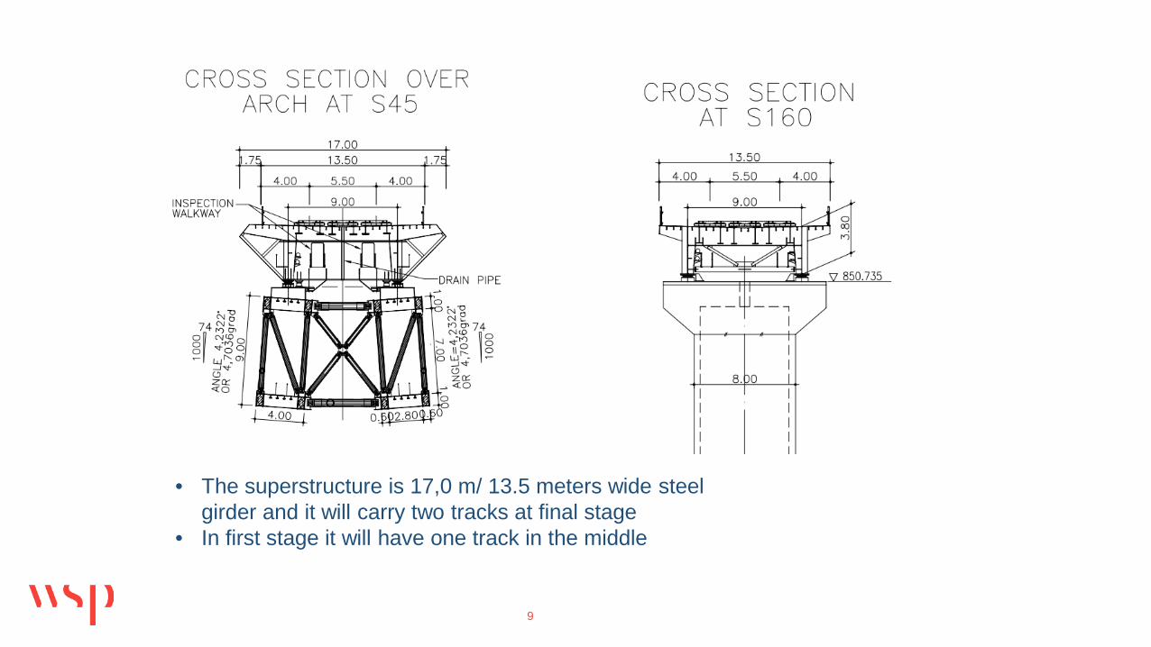
• The superstructure is 17,0 m/ 13.5 meters wide steel girder and it will carry two tracks at final stage
• In first stage it will have one track in the middle

The arch and arch piers of the Chenab Bridge will be made from steel trusses.
3. Some Exceptional Design Parameters
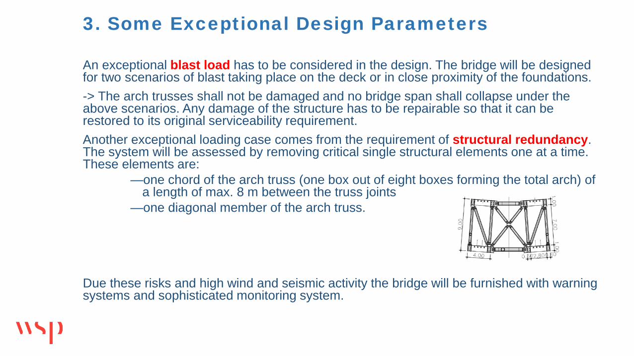
An exceptional blast load has to be considered in the design. The bridge will be designed for two scenarios of blast taking place on the deck or in close proximity of the foundations. -> The arch trusses shall not be damaged and no bridge span shall collapse under the above scenarios. Any damage of the structure has to be repairable so that it can be restored to its original serviceability requirement.Another exceptional loading case comes from the requirement of structural redundancy. The system will be assessed by removing critical single structural elements one at a time. These elements are:
—one chord of the arch truss (one box out of eight boxes forming the total arch) of a length of max. 8 m between the truss joints
—one diagonal member of the arch truss.
Due these risks and high wind and seismic activity the bridge will be furnished with warning systems and sophisticated monitoring system.

4. Wind EngineeringWhen entering to the detailed design stage, one of the key-issues was the exact value of the design wind velocity itself. Because the high hills and the deep gorge, mean wind velocity, gust wind velocity and turbulence characteristics all varies strongly with wind direction
• Wind properties were studied in-detail in the first part of the wind-tunnel test program with large size scale model of the topography.
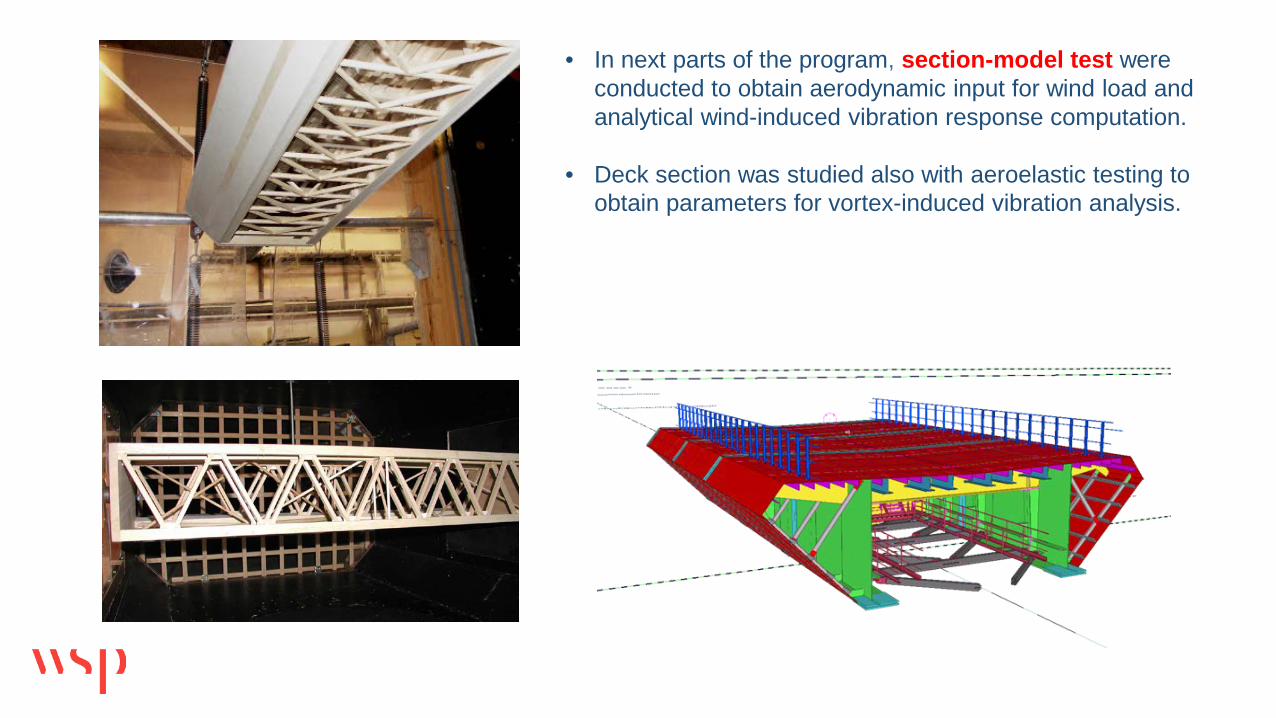
• In next parts of the program, section-model test were conducted to obtain aerodynamic input for wind load and analytical wind-induced vibration response computation.
• Deck section was studied also with aeroelastic testing to obtain parameters for vortex-induced vibration analysis.

14
• Two deck shapes were studies: with and without wind nosing
• The design adopted the one with the nosing due to smaller lateral force coefficient.

The analytical wind response computation was done by multimode frequency-domain analysis by taking into account the results of the terrain and section model tests. Static equivalent wind loads were derived for structural engineer to use in design of the in-service bridge and construction stages. Finally, the analysis and wind-resistance of the completed bridge was confirmed with full aeroelastic model test

5. Detailed Design I
In the design work the National Codes of India, Indian Railway Standards (IRS), Indian Road Congress (IRC) recommendations and Indian Standards (IS) have been supplemented with International standards like British Standards (BS), Eurocode and standards of the International Union of Railways (UIC).
Although international codes could be considered, BS:5400 is preferred.
Basic rail loading is as per MBG: 1987 from the Indian Codes.
The bridge will be designed for seismic loads according to IS 1893, Part 1, 2002, Zone V and site specific spectral studies as carried out by IIT, Roorkee. A challenging 50 % of this seismic loading must be considered in erection stages.
All steel structures have been 3D-modelled and workshop drawings are produced from the TEKLA Model – this procedure has been very successful at the moment, since the Contractor has younger engineers at site who can work with the model prepared by the Designer
Foundations and Piers
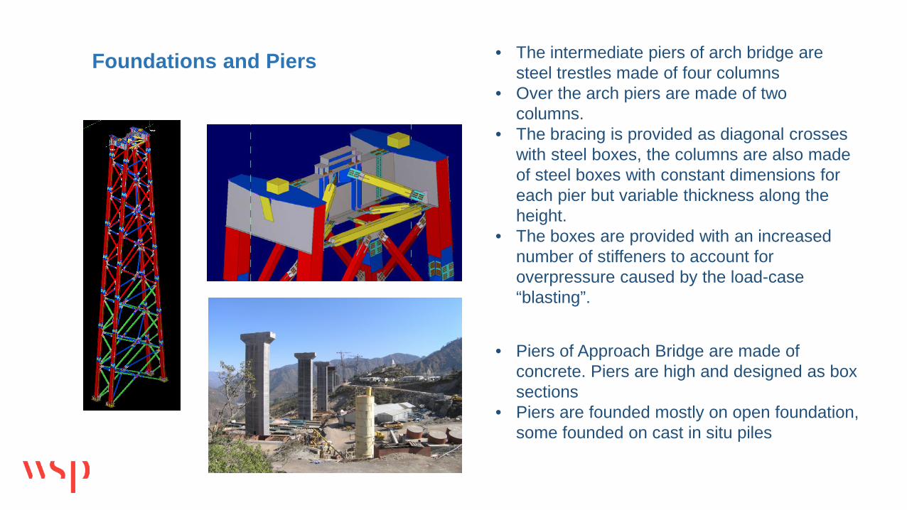
• Piers of Approach Bridge are made of concrete. Piers are high and designed as box sections
• Piers are founded mostly on open foundation, some founded on cast in situ piles
• The intermediate piers of arch bridge are steel trestles made of four columns
• Over the arch piers are made of two columns.
• The bracing is provided as diagonal crosses with steel boxes, the columns are also made of steel boxes with constant dimensions for each pier but variable thickness along the height.
• The boxes are provided with an increased number of stiffeners to account for overpressure caused by the load-case “blasting”.

Superstructure
The principle of cross section of the superstructure is the same in both bridge portions. It consists of two open girders with stiffened steel deck plate and lateral and vertical stiffening steel trusses.
Rails will be connected to the deck by steel sleepers commonly used in India.
The closed deck keeps the rainwater out and provides mostly dry environment below the deck.
Wind noses of the deck are provided in the main arch portion.

Arch The arch and arch piers of the Chenab Bridge will be made from steel
trusses. Primary members (arch main chord, arch pier legs, and diagonals) are
hollow box sections, secondary members are circular. The main chords of arch consist of two hollow boxes connected by a continuous steel plate.
It was initially intended to use pipes for all members of the arch, in order to minimize wind resistance and to further simplify the geometry of joints. This solution was discarded since it relied on site welding of the pipe splices.

Four hollow box sections are combined into one of two strings forming the total arch.
The bracings connecting the two strings are laid out in 3D such that the arch can ’breathe’ without any constraining forces from the bracings.
The main chord members will be filled with self-compacting concrete for enhanced overall stiffness and robustness, with theadded benefit that buckling of the steel plates is suppressed and the need for stiffeners inside the box limited.

21
Major Quantities :
ITEM Unit Tot al Quant i t y
Concrete Cum 67,0 57
Reinforcement Steel
MT 8,226
Excavation Cum 1 0 33 ,0 0 0
Structural Steel MT 30 40 0
6. Construction

Construction Methods Steel girder of Approach Bridge will be launched on concrete piers from
both sides and welded together in the middle Steel Arch will be erected by cable crane in pieces and bolted together –
steel girder will be launched from both sides towards the crown of main arch

The steel structures are manufactured in 4 workshops built close to bridge site. Biggest workshop is just behind the abutment of Approach Bridge, from where deck segments can be launched to final position
The superstructure was launched to its position despite the non-constant radius of the curved alignment – temporary sliding bearings enabled transversal moving – guiding was constructed in the middle of the cross section
23
Approach Bridge

24

Arch foundations are huge – height of foundation with pier of S40 is 57 metres, where size of two foundation slabs is 35x16,5x 8 each.
Big part of the reinforcement bars have been lifted to formwork by cable crane which has worked well so far Excavation of final rock slopes took two years practically done continuously in three shifts
25
Arch Foundations

26

The steel piers are high, longest is 120 metres in height
Pies are preassembled before painting and transportation
All parts are assembled by cable crane which is challenging due wind and huge lifting height
27
Steel piers

28
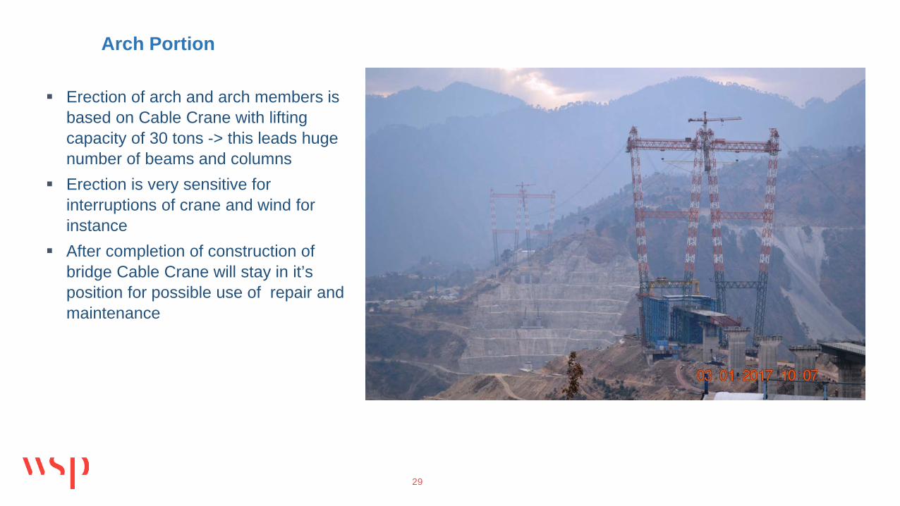
Erection of arch and arch members is based on Cable Crane with lifting capacity of 30 tons -> this leads huge number of beams and columns
Erection is very sensitive for interruptions of crane and wind for instance
After completion of construction of bridge Cable Crane will stay in it’s position for possible use of repair and maintenance
29
Arch Portion

30
All steel members of arch are connected together by bolting –this is because the Client don’t allow welding outside workshops, only segments of superstructure are allowed to welded behind abutments
All steel parts are preassembled before transportation to their final position
Steel parts are connected together by bolting

31
Th e e re c t ion o f th e a rch b rid g e w ill b e d on e b y ca b le c ra n e on ly
Usin g in te rm e d ia te t e m p ora ry t ie -b a ck ca b le s to st a b ilize th e ca n t ile ve rin g st ru c tu re .
Te m p ora ry tow e rs w ill b e e re c te d on top o f tow e r p ie rs in o rd e r to a ch ie ve a st e e p e r a n g le o f th is t e m p ora ry st a y su p p ort .
Fa b rica t ion o f st e e l m e m b e rs w ill b e d on e in w ork sh op s loca te d on b o th sid e s
Ere c t ion st a g e o f a rch is con t ro lle d b y m on ito rin g syste m in o rd e r to g u a ra n te e g ood g e om e t ry con t ro l a n d sa fe lift in g op e ra t ion s

32
Arch w ill b e con n e c te d tog e th e r in th e m id d le b y ja ckin g a rch p o rt ion s in rig h t p osit ion
Fo llow in g th e a rch c lo su re , th e con cre t in g o f st e e l b oxe s o f m a in st e e l ch o rd s w ill t a ke p la ce
Th e p ie rs ove r th e a rch w ill b e e re c te d b y ca b le c ra n e
Te m p ora ry ca b le s w ill b e re m ove d

After a ll p ie rs h a ve b e e n a sse m b le d , t h e p ie r h e a d s w ill b e con n e c t e d tog e th e r b y h o rizon ta l t ie ca b le s t h a t a re a n ch ore d to t h e a b u tm e n t s.
Du e to t h e t ie s, t h e b e n d in g m om e n t s in t h e p ie rs a re ra th e r sm a ll w h e n th e d e ck is la u n ch e d a c ross in to it s fin a l p osit ion .
La u n ch in g o f st e e l g ird e r w ill b e sim u lt a n e ou sly from b o th sid e s in o rd e r t o ke e p a rch d e fo rm a t ion a n d g e om e t ry in con t ro l
Fin a lly b o th sid e s w ill b e con n e c t e d n e a r t h e m id d le p o in t
Fin a l b e a rin g s w ill b e a sse m b le d Fu rn ish in g th e d e ck

Thank you