Embed Size (px)
Citation preview
Chi-Cheng Lin, Winona State University
CS430 Computer Graphics
Introduction
2
Topics
Introduction Applications Elementary Output Primitives Graphics Output Devices Graphics Input Devices Graphics Software Standards Interactive Computer Graphics
3
Introduction What is Computer Graphics? History
Whirlwind Computer 1950, MIT Computer-driven CRT (Cathode Ray Tube) displays
Sketchpad drawing system 1963, Ivan Sutherland Interactive graphics: keyboard and light pen Data structures
DAC system 1964, GM Automobile design (CAD/CAM)
4
Introduction
History (cont’d)Bitmap graphics
Apple and PC Bitmap:
– A ones and zeros representation of the rectangular array of points on the screen.
– The points are called pixels or pels (picture elements).
GUIs SIGGRAPH: www.siggraph.org Why computer graphics?
5
Applications
Art, entertainment, publishing Image processing Monitoring manufacturing
processes Displaying simulation CAD Scientific analysis and visualization
6
Elementary Output Primitives
Polyline Curves Text Filled region Raster image
Each primitive is associated with a set of attributes
7
Polyline
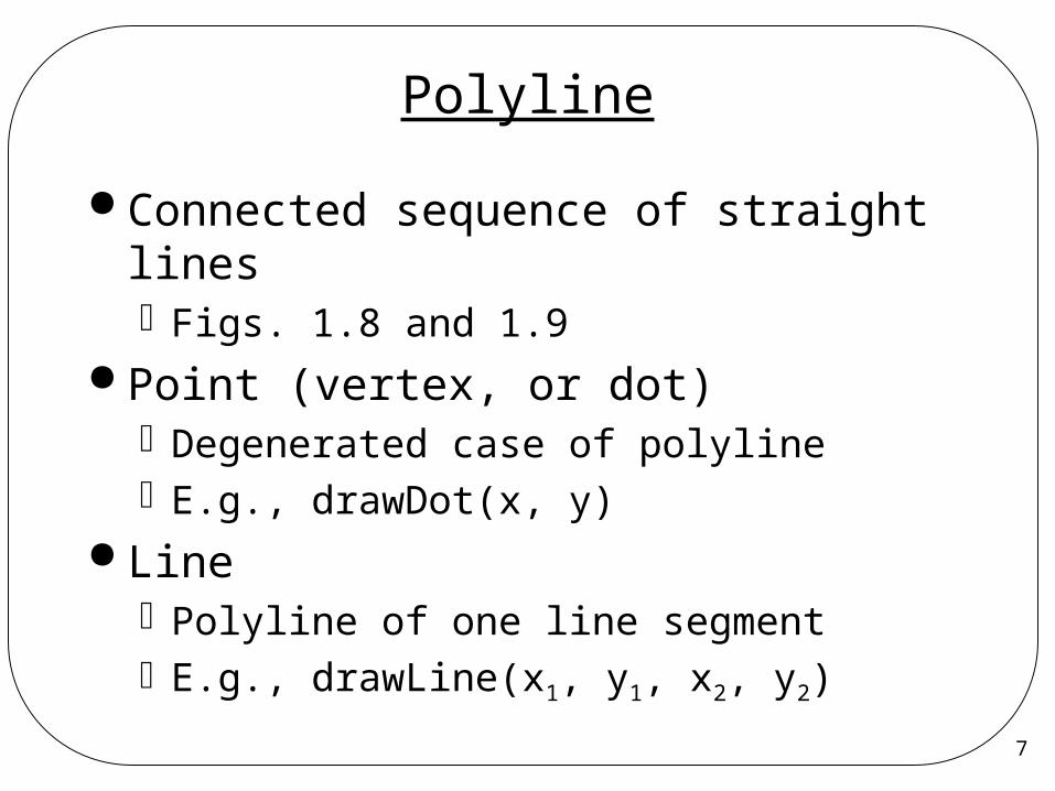
Connected sequence of straight linesFigs. 1.8 and 1.9
Point (vertex, or dot)Degenerated case of polylineE.g., drawDot(x, y)
LinePolyline of one line segmentE.g., drawLine(x1, y1, x2, y2)
8
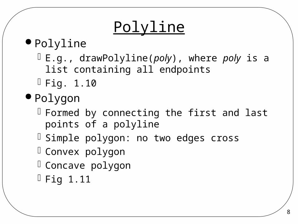
Polyline Polyline
E.g., drawPolyline(poly), where poly is a list containing all endpoints
Fig. 1.10 Polygon
Formed by connecting the first and last points of a polyline
Simple polygon: no two edges crossConvex polygonConcave polygonFig 1.11
9
Attributes of Polyline
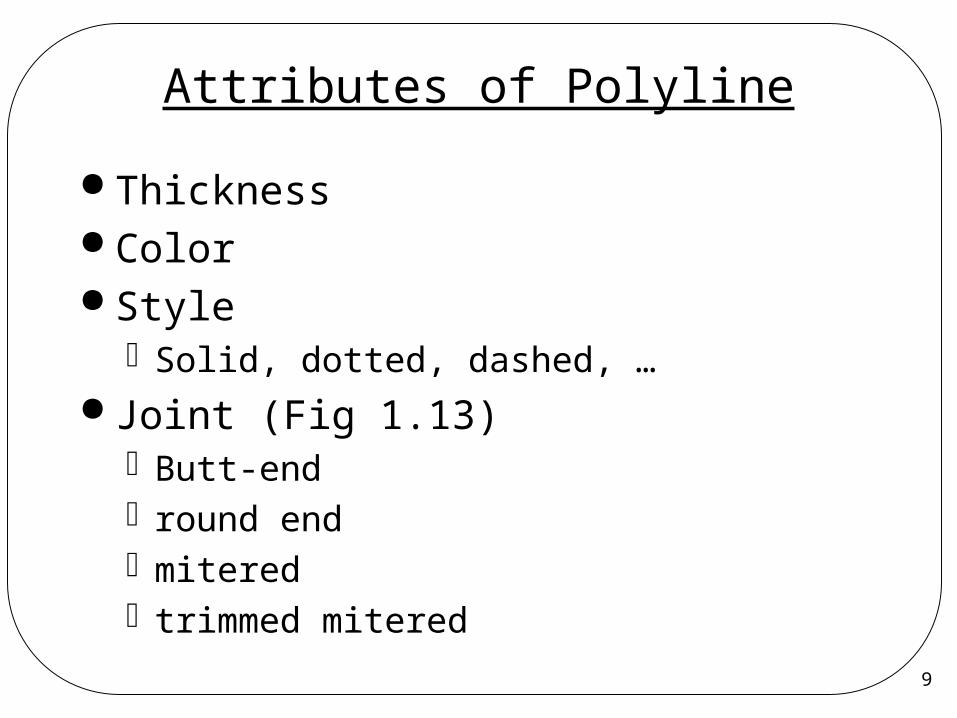
Thickness Color Style
Solid, dotted, dashed, … Joint (Fig 1.13)
Butt-endround end miteredtrimmed mitered
10
Curves
Circle Ellipse Parabola Hyperbola B-spline NURBS
Attributes?
11
Text Character string Shape defined by (Fig. 1.16)
Bit mapPolyline or curve
E.g., drawString(x, y, string) Attributes
Font or “type face” (Fig. 1.15) SizeSpacingorientation
12
Filled Region (Area)
Shape filled with color or patternFigs. 17 and 18
Boundary is usually a polygon E.g., fillPolygon(poly, pattern) Attributes
Attributes of enclosing borderPattern of fillingColor of filling
13
Raster Image
Image made up of pixels (Fig. 1.19)
Stored as a 2D array of numerical values (Fig. 1.20)Bit map: 1 bit per pixelPixel map: >1 bits per pixel
Formatspbmppm
14
Gray-Scale Raster Image
Pixel depth:#bits needed to represent the gray
level of a pixel1 bit: bi-level, black-and-white,
monochrome (Fig 1.26)2 bits: 4 gray levels4 bits: 16 gray levels
:8 bits: 256 gray levels

15
Color Raster Image
Color valueOrdered triple (r, g, b) representing
intensities of red, green, blue, respectively Color depth:
#bits used to represent the color of a pixelE.g., color depth = 3
(0,0,0) = black, (1,1,1) = white(0,0,1) = blue, (1,0,0) = red, (1,0,1) = ?
Q: how many colors can be represented?
16
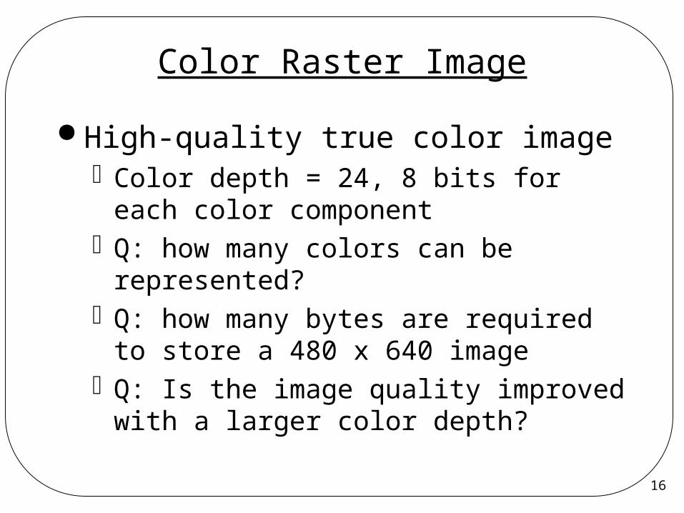
Color Raster Image
High-quality true color imageColor depth = 24, 8 bits for each color
componentQ: how many colors can be
represented?Q: how many bytes are required to
store a 480 x 640 imageQ: Is the image quality improved with
a larger color depth?
17
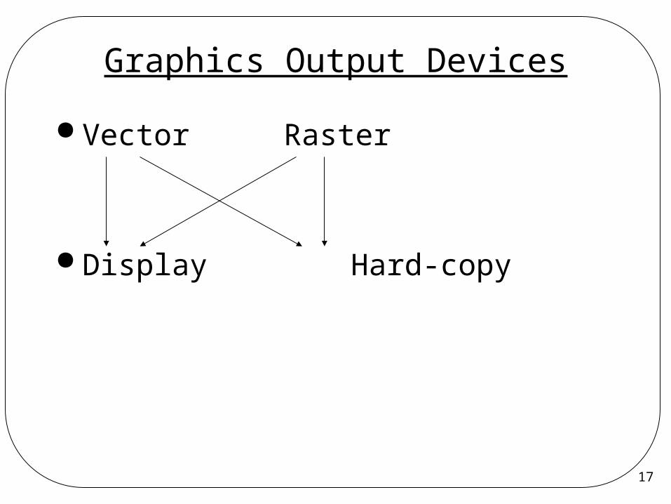
Graphics Output Devices
Vector Raster
Display Hard-copy

18
Vector Display
Electron beam deflected from endpoint to endpoint
One line at a time, similar to pen plotter Dictated by display commands Random Scan, refresh required Display processor must cycle through display
list to refresh CRT's phosphor at least 60 times per second (60Hz) to avoid flicker.
Image changed by changing display commands in the list
19
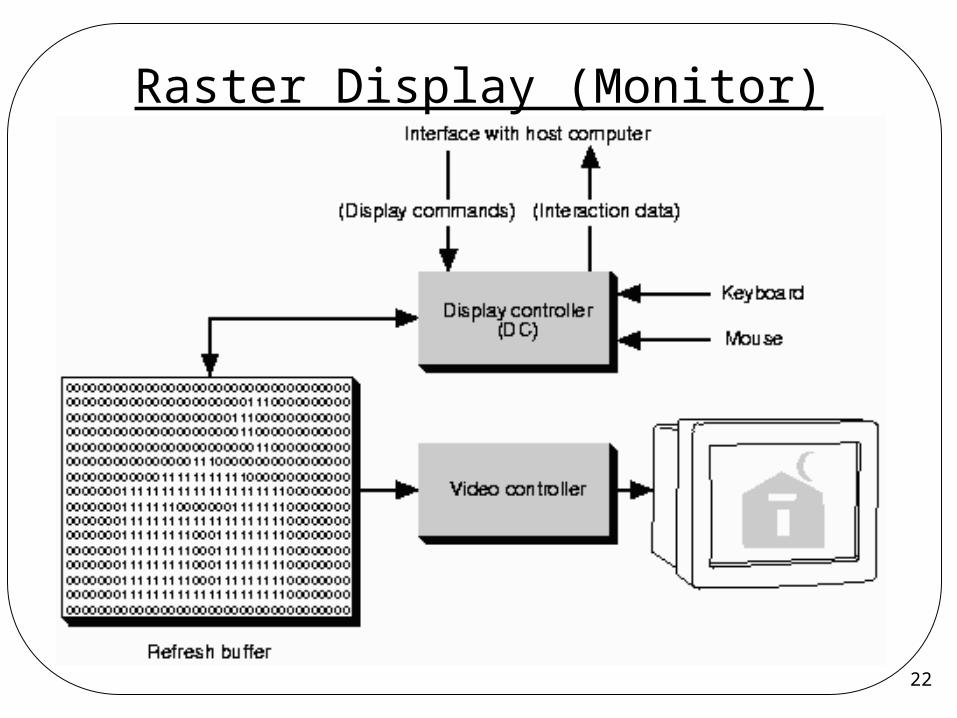
Raster Output Device 2D display surface Built-in 2D coordinate system, either
upside-down or not (Fig. 1.35) A position on the display surface is
associated with an image pixel Frame buffer
A region of memory to hold all of the pixel values for the display surface
Where is it in a computer? Block diagram (Fig. 1.36)
20
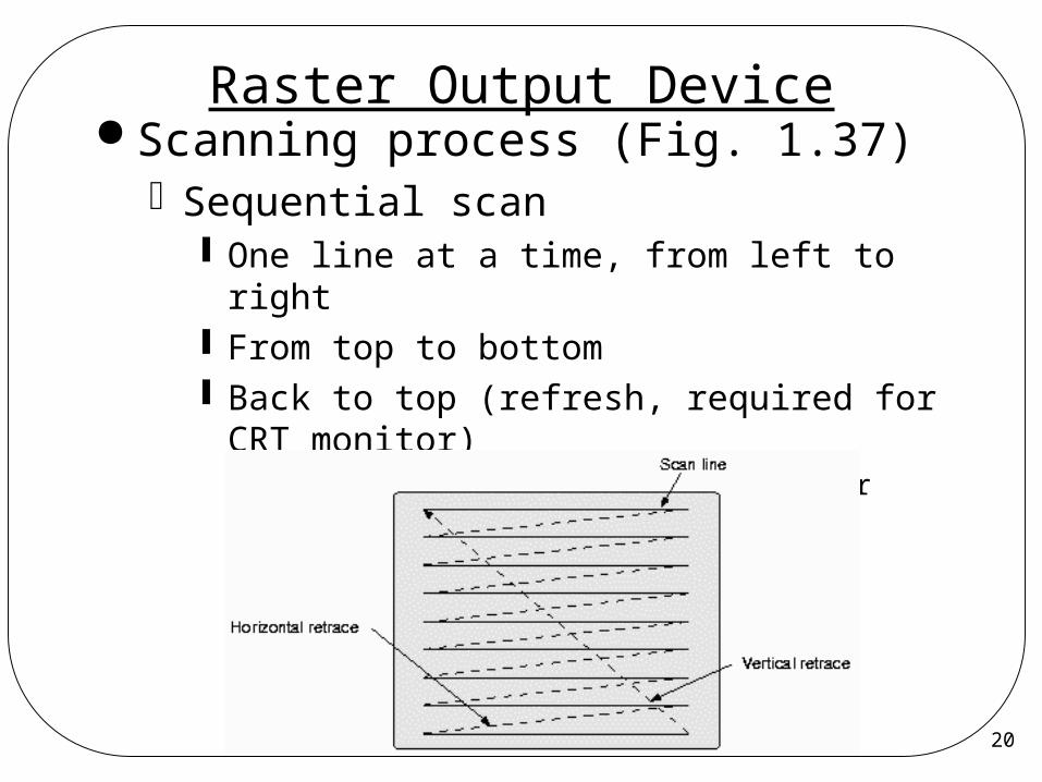
Raster Output Device Scanning process (Fig. 1.37)
Sequential scan One line at a time, from left to right From top to bottom Back to top (refresh, required for CRT
monitor)– Refresh rate must be >60 times per second to
prevent flicker
21
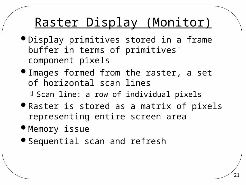
Raster Display (Monitor) Display primitives stored in a frame
buffer in terms of primitives' component pixels
Images formed from the raster, a set of horizontal scan linesScan line: a row of individual pixels
Raster is stored as a matrix of pixels representing entire screen area
Memory issue Sequential scan and refresh
22
Raster Display (Monitor)
23
Raster Display (Monitor) Beam's intensity set to reflect
pixel's intensity at each pixel Color Systems
Three beams, RED, GREEN, and BLUE, are controlled
Two types True color display system Indexed color display system
24
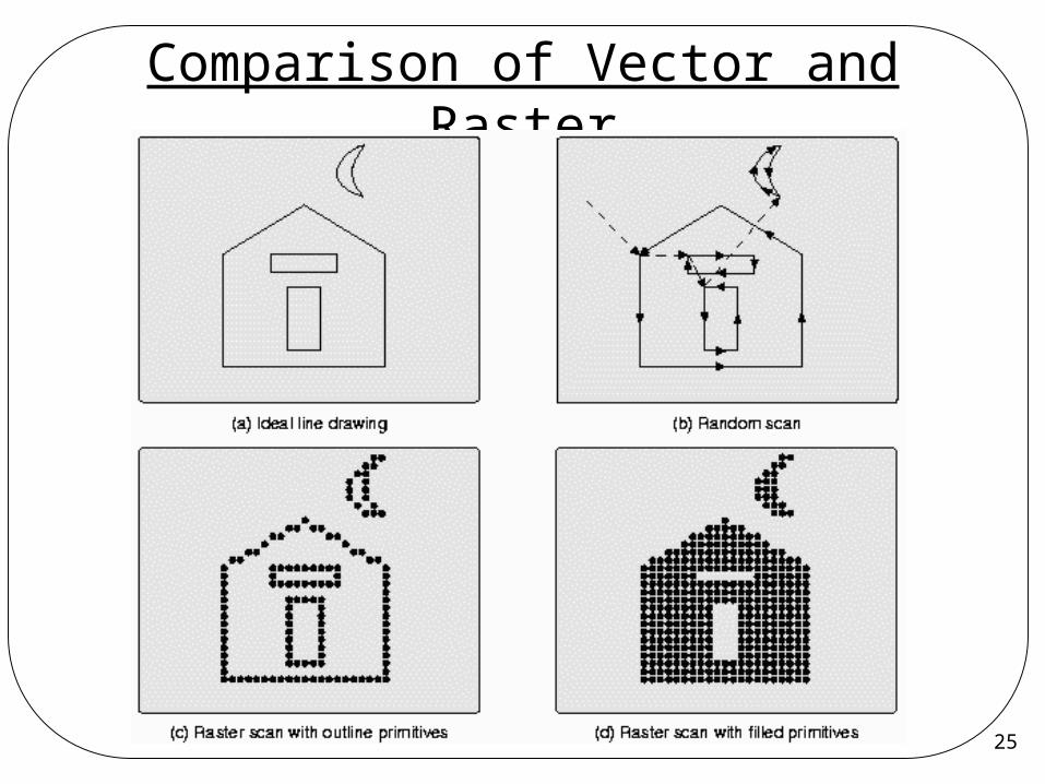
Comparison of Vector and Raster
Raster DisplaysAdvantages
Lower cost Ability to display filled area
Disadvantages Discrete nature of pixel presentation Aliasing: Jaggies or staircasing caused by
approximation
25
Comparison of Vector and Raster
26
True-color Display System
Operation (Fig. 1.38)
27
Indexed-Color Display System Pseudo-color display system Color lookup table (LUT)
Pixel value used as an index into LUTProgrammablePalette: set of possible colors can be displayed
If color depth=b and LUT width=w2w colors can be displayed, any 2b at one time
Example (Fig1.40): 6 bpp, 15-bit color32K colors can be displayed, 64 at one timeThe display has a palette of 32K colors
28
Comparisons of Color Systems Example (Fig 1.41):
1024x1280-pixel-displayTrue color system, color depth = 24
Memory requirement:1024 x 1280 x 24 4MB
Indexed color system, color depth = 8, width of LUT = 24 bits Memory requirement:
1024 x 1280 x 8 + 256 x 3 1MB Indexed color displays with LUT is much
cheaper than true color systems!!
29
Hard-Copy Output Devices
PlotterFlatbed plotterDrum plotter
Dot matrix printer Laser printer Inkjet printer Film recorder
Which are vector and which are raster?
30
Graphics Input Devices
Logical input devices (primitives)StringChoiceValuatorLocatorPick
31
Graphics Input Devices Physical input devices
KeyboardButtonsMouseTabletJoystick and trackballKnobsSpace ball and data gloveDigitizing 3D objects and capturing motion
Which physical input devices are suitable for a particular logical input device?
32
Graphics Software Standards
Core3D Core graphics SystemProduced by an ACM SIGGRAPH
committee GKS
Graphics Kernel System2DGKS-3D, 1988Groups of primitives arranged as
segments, but not nested
33
Graphics Software Standards PHIGS
1988 (Programmers Hierarchical Interactive Graphics System)
Nested structuresStructure databasesPHIGS PLUS: includes shading and lightingComplicated, large
de facto Standards:PEX (PHIGS Extension to X)PostScriptOpenGL
34
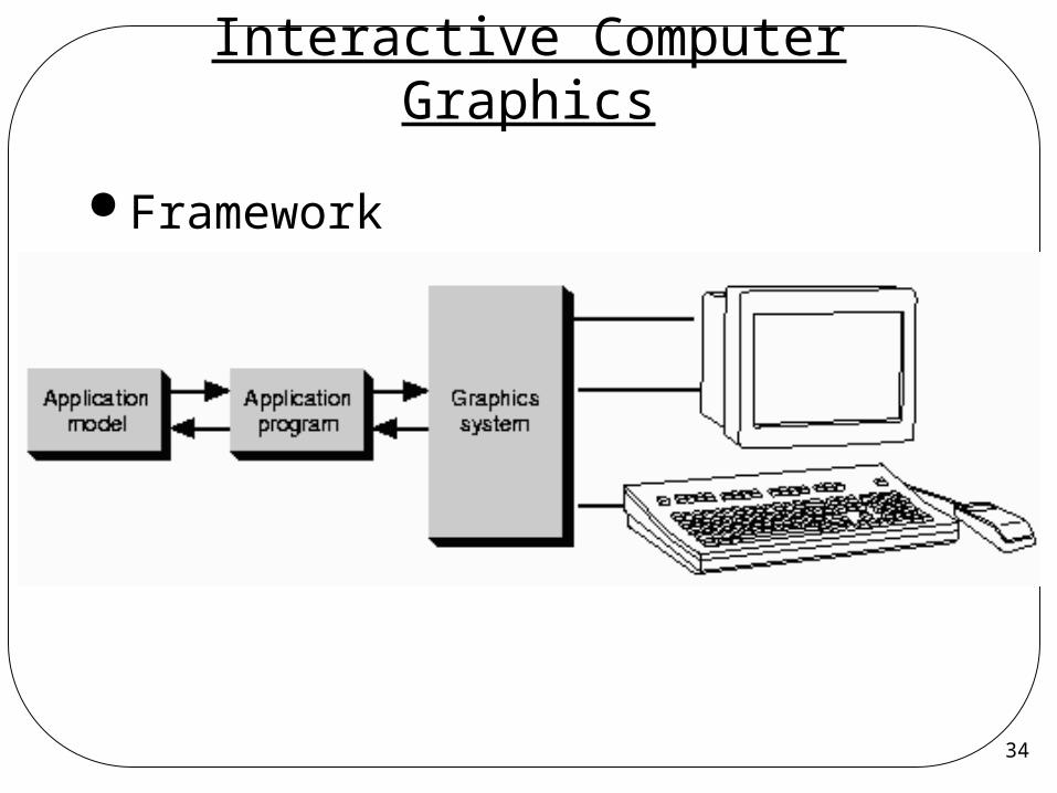
Interactive Computer Graphics
Framework
35
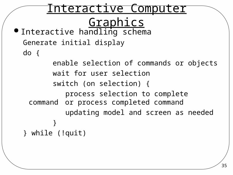
Interactive Computer Graphics Interactive handling schema
Generate initial displaydo { enable selection of commands or objects wait for user selection switch (on selection) { process selection to complete command
or process completed command updating model and screen as needed }} while (!quit)