Embed Size (px)
Citation preview

I
CHILLED BEAM SYSTEMSCHILLED BEAM SYSTEMS
AIR-FIT® TYPE
ONLINE SELECTION TOOL www.beamadvisor.nl

2 © 05-2020 | Barcol-Air B.V. | T +31 (0)299 689300 | www.barcol-air.nl | changes w/o notice or obligation
Rendering of a Chilled beam Airfit model 600
Cross section rendering of a Chilled beam Airfit model 600

3© 05-2020 | Barcol-Air B.V. | T +31 (0)299 689300 | www.barcol-air.nl | changes w/o notice or obligation
Chilled beam systems AIR-FIT®
Type designation
A 3 O 4 1 7 9 4 - 2 9 5 O O B B B O
1 2 3 4 5 6 7 8 9 10 11 12 13 14 15 16 17 18
Composition type designation:
Position Code Description
1 + 2 Product A3 AIR-FIT®
3 Type O Standard 1 Non standard, specify separately
4 Finish 4 RAL 9010, 70% gloss grade (standard) 1 Non standard, specify separately
5 + 6 + 7 + 8 Length .... Actualfrontlengthinmm(accordingtocustomerspecifications)
9 Hyphen between length and width 10 + 11 + 12 Width ... Standardwidthinmm(accordingtocustomerspecifications)
13 Connection L/R Waterside connection (left / right) O Top connection (plenum box type B) 14 Options O Standard 1 Special options, specify separately
15 Plenum box S Plenum box with side connection B Plenum box with top connection V Side connection on plenum box with reduced height (model 300 only) 1 Special plenum box
16 Coilconfiguration A 2-Pipeconfiguration B 4-Pipeconfiguration C Highcapacity,2-pipeconfiguration(model600only) D Highcapacity,4-pipeconfiguration(model600only) 1 Specialconfiguration
17 Nozzle plate A Nozzle type 1, not adjustable B Nozzle type 2, not adjustable C Nozzle type 3, not adjustable D Nozzle type 4, not adjustable E Nozzle type 5, not adjustable F Nozzletype6,notadjustable G Nozzle type 2 or 3, adjustable H Nozzle type 4 or 5, adjustable 1 Special nozzle type (according to drawing) O Not applicable (without nozzles)
18 Nozzle position in case of an adjustable nozzle type O Not adjustable B Position 2 (with nozzle plate G only, nozzle type 2) C Position 3 (with nozzle plate G only, nozzle type 3) D Position 4 (with nozzle plate H only, nozzle type 4) E Position 5 (with nozzle plate H only, nozzle type 5)
Connections (top view):
Connection O = plenum box type B
Connection L = water left side
Connection R = water right side

4 © 05-2020 | Barcol-Air B.V. | T +31 (0)299 689300 | www.barcol-air.nl | changes w/o notice or obligation
Chilled beam systems AIR-FIT®
Technical data
AIR-FIT® model 300 AIR-FIT® model 600
Maintenance- Removable front panel which is equipped with
a safety catch
Heat exchanger- Waterside connection R/L (see page...)- 2-pipe or 4-pipe system- Standard or high capacity- Tubes: copper- Fins: aluminium- Pressure tested: 15 bar- Blackened coils (optional)
Plenum box- Galvanised sheet steel- Airside connection(s) top or side- Uninsulated (standard) or insulated (optional)
Finish- RAL 9010, 70% gloss grade (standard)-Adifferentfinishavailableonrequest
Features AIR-FIT® chilled beams
High capacityThe active chilled beam has a high cooling and heating capacity and is suitable to ventilate, cool and heat (commercial) buildings. Model 600canbesuppliedwithadifferentcoiltype,suitable for high capacity solutions (additional cost).
Compact in size A chilled beam with a size of only 1800 x 300 mm, 10 m2officespaceissuppliedwithsuf-ficientventilatedair,coolingandheating.In addition, the active chilled beam is relatively light weight and needs minimum installation space.
Simplicity in mountingWith a width of 295 or 595 mm, the active chil-led beam can be easily integrated into suspen-ded ceilings with exposed T or bolt-slot systems for intermediate mounting.
Low noiseTheefficientlyshapednozzlescreate(atmini-mal primairy air pressure) a maximum induction at a minimum sound level.
Low maintenanceTheactivechilledbeamhasnofilter,nofanorany other moving parts, therefore maintenance is limited to cleaning the heat exchanger occa-sionally. The heat exchanger can be accessed simply by removing the bottom panel, which is equipped with a safety catch.
ControlsThe active chilled beam can be controlled in manydifferentways.Wecanprovideasolutionfor every (integrated) application. For support please contact us.
Ceiling locationThe active chilled beam will supply air into the roomthroughtwooppositeslots.Inoffice applications the unit can be located in the middle of the room, either perpendicular or parallel to the facade.
FlexibilityTheactivechilledbeamisavailableindifferentlengths. This makes it possible to select the necessary capacity for every installation.
Plenum box variety The standard active chilled beam is supplied with a top or side connection.
Adjustable nozzle types The active chilled beam is standard equipped withafixednozzlepositionfortherequiredfresh air discharge. Optionally an adjustable nozzle bar is available. In this case adjusting the nozzles after mounting is possible.
Available options are: adjustable between nozzle size 2 and 3 or 4 and 5. Air connection of largest nozzle size will be provided.
Air distribution AIR-FIT®
Operating principle of the AIR-FIT®

5© 05-2020 | Barcol-Air B.V. | T +31 (0)299 689300 | www.barcol-air.nl | changes w/o notice or obligation
A
E
295
212ØD
145
30
21210ØD
115
E 145
30
E
= =
A
30
A
105
hanging brackets Ø7 (4x)
Chilled beam systems AIR-FIT®
Dimensions model 300
Dimensions AIR-FIT® 300
Model 600 1200 1500 1800 2400 3000
A (standard) 594 1194 1494 1794 2394 2994
A (minimum) 594 1118 1418 1718 2318 2918
D5 Ø 98 Ø 98 - Ø 123 Ø 98 - Ø 158 Ø 98 - Ø 158 Ø 123 - Ø 198 Ø 123 - Ø 198
E 480 1000 1300 1600 2200 2800
Weight (kg)3 7,5 14,0 17,0 20,5 27,0 34,0
AIR-FIT® with side connection (optional)
AIR-FIT® with reduced plenum box height (optional) AIR-FIT® with top connection (standard)
Side view version withside connection orreduced plenum box height
Side viewversion with top connection
Notes dimensional data:
1. Measurement in mm. 2. Weight in kg including the water contents baded on a unit with side connection, standard 4-pipe coil and adjustable nozzle. 3. The length of the active chilled beam depends on the ceiling type (please consult your ceiling supplier for the exact measurements). The exact length needs to specified when ordering.4. The diameter of the inlet depends on the nozzle type (see table page 25).

6 © 05-2020 | Barcol-Air B.V. | T +31 (0)299 689300 | www.barcol-air.nl | changes w/o notice or obligation
Chilled beam systems AIR-FIT®
Dimensions model 600
Dimensions AIR-FIT® 600
Model 600 1200 1500 1800 2400 3000
A (standaard) 594 1194 1494 1794 2394 2994
A (minimaal) 594 1118 1418 1718 2318 2918
D5 Ø 98 Ø 98 - Ø 158 Ø 98 - Ø 198 Ø 123 - Ø 198 Ø123-2xØ160 Ø 123 - 2 x Ø 198
G 370 370 370 370 370 - 2 x 370 370 - 2 x 370
H nvt nvt nvt nvt nvt - 5406 nvt-6906
Massa (kg)3 12,5 23,5 28,0 33,5 45,0 55,0
AIR-FIT® with side connection (optional)
==
H 6 H 6
30
A
595
ØD
162
40
235
hanging brackets (4x) extra hanging brackets (2x)for models 2400 & 3000
AIR-FIT® with top connection (standard)
Side view Version with side connection
Side viewVersion with top connection
A
30
595
H 6 H 6
G
ØD
255
30 342
11
162
hanging brackets (4x) extra hanging brackets (2x)for models 2400 & 3000
Notes dimensional data:
1. Measurement in mm. 2. Weight in kg including the water contents based on a unit with side connection, standard 4-pipe coil and adjustable nozzle.3. The length of the active chilled beam depends on the ceiling type (please consult your ceiling supplier for the exact measurements). The exact length needs to specified when ordering.4. The diameter of the inlet depends on the nozzle type (see selection tables).5. Models 2400 and 3000 are equipped with one or two airside connections, the extact number depends on the choosen nozzle type (see table on page 25).

7© 05-2020 | Barcol-Air B.V. | T +31 (0)299 689300 | www.barcol-air.nl | changes w/o notice or obligation
The data mentioned in this document can be used as an indication. For an exact selection we refer to the selection software which is available at our website www.beamadvisor.nl.
Chilled beam systems AIR-FIT®
Selection example
Given:
Officespace(LxWxH) = 5.4x3.6x2.7mRequired active chilled beam type = 1800 x 300 mm, 2xFresh air supply (2-way ventilation) q1 = 106m3/h, 53 m³/h per active chilled beamRequired cooling capacity at 25 °C room temperature (Troom), 55% RV Ptot = 1000 W (500 W / unit)Required heating capacity at 20 °C room temperature (Troom) Ptot = 1000 W (500 W / unit)Temperature cooling water TW,in = 16°CTemperature heating waterTW,in = 40 °CTemperature air supply, summer T1 = 17 °CTemperature air supply, winter T1 = 17 °C
Solution:
For the selection the tables on page 11 (cooling) and 14 (heating) are used, belonging to model 1800 x 300.Pleaeselecttheexactnozzlefirst. Each nozzle type as stated in the table has got a minimum (qmin) and a maximum (qmax) air quantity. By interpolation an indication for the intermediate value can be obtained.
Nozzle type Selection from the table, based upon an acceptable static pressure, sound power level and throw. 2Static pressure, airsided Calculation:
Δp=(q1 / qmax)^2*Δpmax = (53 / 85)^2 * 200 = 78 Pa78 Pa
Throw Interpolating throw dataThrow per m³/h (Wm3) for nozzle 2:Wm3 = (Wmax – Wmin) / (qmax - qmin) = (3,7 – 1,7) / (85 – 45) = 0,05 m/m³/hThrow at 53 m³/h = 1,7 + (53-45) * 0,05 = 2,3 mNote: in winter situations the throw is of no importance because heated air will not cause any draft.
2,3 m
Sound power level Interpolating sound power level dataSound power level per m³/h (Lw,m3) for nozzle 2:Lw,m3 = (Lw,max - Lw,min) / (qmax - qmin)= (39 - 22) / (85 - 45) = 0,43 dB/m³/hSound power level at 53 m³/h = 21 + (53-45) * 0,43 = 24 dB(A)
24 dB(A)
Summer situation:Cooling capacity fresh air Please use the calculation help as stated beneath the table:
PL = 0,335 * q1 * (Truimte – T1)=0,335*53*(25-16)=160W160W
Required cooling capacity water
Pw = Ptot – PL=500–160=340W 340 W
Watersided power level Interpolating coil dataPower level per m³/h (PL,m3)atΔT=10Kandqw 170 l/h:PL,m3 = (Pw,max – Pw,min) / (qmax - qmin)= (540–375) / (85-45) = 4,1 W/m³/hPower level at 53 m³/h = 375 + (53-45) * 4,1 = 408 WΔT=9Kleadstoapproximately12%reduction(seecalculationhelpasstatedbeneaththetable)Pw,9=408/1,12=364W
364W
Water quantity See table 170 l/hPressure loss, watersided See table 10,5 kPaΔTw (water out - water in) ΔT=Pw / (qw*1,16)=364/(170*1,16) 1,85K
Winter situation:Heating capacity fresh air PL = 0,335 * q1 * (Tair – Troom) = 0,335 * 53 * (17-20) = -53 W -53 WRequired capacity water Pw = Ptot – PL = 500 – (-53) = 553 W 553 WWatersided power level Interpolating coil data
Powerlevelperm³/hatΔT=20Kandqw 50 l/h:PL,m3 = (Pw,max – Pw,min) / (qmax - qmin)=(670-540)/(85-45)=3,3W/m³/hPowerlevelat53m³/h=540+(53-45)*3,3=566W
566W
Water quantity See table 50 l/hPressure loss, watersided See table 0,8 kPaΔTw (water in - water out) ΔT=Pw / (qw*1,16)=566/(50*1,16)=9,8 9,8K
Calculation help: Cooling capacity air PL = 0,335 * (Troom - Tair) * q1 Temperate difference between water in and out (Twater,out - Twater,in) = PW / (1,16 * qw)Cooling capacity of the temperature difference (Troom - Twater,in) which leads to an extra capacity of 12% per degree.If several units are connected together, this will lead to an extended throw of 10%.

8 © 05-2020 | Barcol-Air B.V. | T +31 (0)299 689300 | www.barcol-air.nl | changes w/o notice or obligation
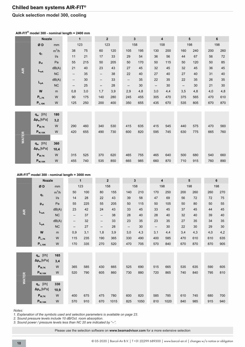
Chilled beam systems AIR-FIT®
Quick selection model 300, cooling
AIR-FIT® model 300 - nominal length = 600 mm
Ø D mm
m3/h 8 14 12 22 20 40 25 50 30 60 40 75
l/s 2 4 3 6 6 11 7 14 8 17 11 21
pst Pa 65 200 55 185 50 190 50 190 50 195 55 195
dB(A) -- 32 -- 32 -- 37 -- 43 21 44 24 42
NC -- 27 -- 27 -- 32 -- 38 -- 39 -- 37
dB(A) -- 22 -- 22 -- 27 -- 33 -- 34 -- 32
NC -- -- -- -- -- 22 -- 28 -- 29 -- 27
W m 0,7 1,8 1,1 2,4 1,8 3,2 1,9 3,4 2,2 3,6 2,6 3,9
PL,7K W 20 35 30 50 45 95 60 115 70 140 95 175
PL,10K W 25 45 40 75 65 135 85 170 100 200 135 250
qw [l/h] 135∆pw [kPa] 3,2
PW,7K W 55 90 65 105 80 135 80 135 85 140 100 150
PW,10K W 85 135 95 155 120 200 120 200 125 210 145 220
qw [l/h] 270∆pw [kPa] 10,5
PW,7K W 65 100 70 115 90 150 90 150 95 155 110 165
PW,10K W 90 145 105 170 130 220 130 220 140 235 160 250
9898 98 98 98
WA
TER
Nozzle 5
AIR
98
q1
LwA
LpA
61 2 3 4
AIR-FIT® model 300 - nominal length = 1200 mm
Ø D mm
m3/h 16 32 25 50 45 90 55 105 65 120 85 145
l/s 4 9 7 14 13 25 15 29 18 33 24 40
pst Pa 55 215 50 205 50 205 50 175 50 165 50 150
dB(A) -- 37 -- 37 25 45 24 45 26 45 30 45
NC -- 32 -- 32 20 40 -- 40 21 40 25 40
dB(A) -- 27 -- 27 -- 35 -- 35 -- 35 20 35
NC -- 22 -- 22 -- 30 -- 30 -- 30 -- 30
W m 0,7 2,6 1,4 3,3 2,5 4,4 2,6 4,4 2,9 4,6 3,4 4,9
PL,7K W 40 75 60 115 105 210 130 245 150 280 200 340
PL,10K W 55 105 85 170 150 300 185 350 220 400 285 485
qw [l/h] 105∆pw [kPa] 3,3
PW,7K W 120 195 140 220 175 250 175 245 180 250 200 255
PW,10K W 175 290 205 325 260 380 260 370 270 370 295 380
qw [l/h] 210∆pw [kPa] 10,6
PW,7K W 125 210 145 245 190 305 185 290 195 295 220 310
PW,10K W 180 310 215 355 280 440 275 420 285 430 320 445
LpA
LwA
q1
6Nozzle 1 2 3 4
WA
TER
123 12398 98 98 123
AIR
5
Please use the selection software on www.beamadvisor.com for a more extensive selection
Notes:1. Explanation of the symbols used and selection parameters is available on page 23.2. Sound pressure levels include 10 dB/Oct. room absorption.3. Sound power / pressure levels less than NC 20 are indicated by “--”.

9© 05-2020 | Barcol-Air B.V. | T +31 (0)299 689300 | www.barcol-air.nl | changes w/o notice or obligation
Chilled beam systems AIR-FIT®
Quick selection model 300, cooling
AIR-FIT® model 300 - nominal length = 1500 mm
Ø D mm
m3/h 22 44 35 70 60 120 75 130 90 160 115 200
l/s 6 12 10 19 17 33 21 36 25 44 32 56
pst Pa 55 220 55 210 50 190 50 145 50 155 50 155
dB(A) -- 38 21 40 24 43 28 45 27 45 29 45
NC -- 33 -- 35 -- 38 23 40 22 40 24 40
dB(A) -- 28 -- 30 -- 33 -- 35 -- 35 -- 35
NC -- 23 -- 25 -- 28 -- 30 -- 30 -- 30
W m 0,7 2,7 1,5 3,5 2,6 4,6 2,8 4,4 3,1 4,8 3,6 5,2
PL,7K W 50 105 80 165 140 280 175 305 210 375 270 470
PL,10K W 75 145 115 235 200 400 250 435 300 535 385 670
qw [l/h] 95∆pw [kPa] 3,3
PW,7K W 160 245 185 275 220 320 220 295 230 310 250 335
PW,10K W 235 365 275 410 330 460 330 435 345 455 370 475
qw [l/h] 190∆pw [kPa] 10,8
PW,7K W 170 280 200 315 245 390 245 350 260 375 280 410
PW,10K W 255 410 300 465 365 550 365 505 385 535 415 570
5 6
AIR
1 2 3 4
123 123 158
WA
TER
Nozzle
98 98
q1
LwA
LpA
158
AIR-FIT® model 300 - nominal length = 1800 mm
Ø D mm
m3/h 27 55 45 85 75 140 95 165 110 185 140 210
l/s 8 15 13 24 21 39 26 46 31 51 39 58
pst Pa 55 220 55 200 50 170 50 150 50 135 50 110
dB(A) -- 39 22 39 27 45 27 45 29 45 33 45
NC -- 34 -- 34 22 40 22 40 24 40 28 40
dB(A) -- 29 -- 29 -- 35 -- 35 -- 35 23 35
NC -- 24 -- 24 -- 30 -- 30 -- 30 -- 30
W m 0,8 2,9 1,7 3,7 2,7 4,6 3,0 4,7 3,2 4,8 3,7 5,0
PL,7K W 65 130 105 200 175 330 225 385 260 435 330 490
PL,10K W 90 185 150 285 250 470 320 555 370 620 470 705
qw [l/h] 85∆pw [kPa] 3,2
PW,7K W 190 280 225 300 255 325 260 320 265 320 280 320
PW,10K W 280 420 335 450 385 475 390 470 395 470 420 475
qw [l/h] 170∆pw [kPa] 10,5
PW,7K W 205 330 250 375 295 450 300 430 305 435 330 435
PW,10K W 305 490 365 540 435 625 440 605 450 605 485 610
61 2 3 4
WA
TER
Nozzle 5
AIR
158
q1
LwA
LpA
15898 123 123 158
Notes:1. Explanation of the symbols used and selection parameters is available on page 23.2. Sound pressure levels include 10 dB/Oct. room absorption.3. Sound power / pressure levels less than NC 20 are indicated by “--”.
Please use the selection software on www.beamadvisor.com for a more extensive selection
10 © 05-2020 | Barcol-Air B.V. | T +31 (0)299 689300 | www.barcol-air.nl | changes w/o notice or obligation
Chilled beam systems AIR-FIT®
Quick selection model 300, cooling
Please use the selection software on www.beamadvisor.com for a more extensive selection
Notes:1. Explanation of the symbols used and selection parameters is available on page 23.2. Sound pressure levels include 10 dB/Oct. room absorption.3. Sound power / pressure levels less than NC 20 are indicated by “--”.
AIR-FIT® model 300 - nominal length = 2400 mm
Ø D mm
m3/h 38 75 60 120 105 195 130 200 160 240 200 260
l/s 11 21 17 33 29 54 36 56 44 67 56 72
pst Pa 55 215 50 205 50 170 50 115 50 120 50 85
dB(A) 21 40 23 43 27 45 32 45 32 45 36 45
NC -- 35 -- 38 22 40 27 40 27 40 31 40
dB(A) -- 30 -- 33 -- 35 22 35 22 35 26 35
NC -- 25 -- 28 -- 30 -- 30 -- 30 21 30
W m 0,8 3,0 1,7 3,9 2,9 4,8 3,0 4,4 3,5 4,8 4,0 4,8
PL,7K W 90 175 140 280 245 455 305 470 375 565 470 610
PL,10K W 125 250 200 400 350 655 435 670 535 805 670 870
qw [l/h] 180∆pw [kPa] 3,2
PW,7K W 290 460 340 530 415 635 415 545 440 575 470 560
PW,10K W 420 655 490 730 600 820 595 745 630 775 665 760
qw [l/h] 360∆pw [kPa] 10,4
PW,7K W 315 525 370 620 465 755 465 640 500 680 540 660
PW,10K W 455 740 535 850 665 985 660 870 710 915 760 890
q1
LwA
LpA
61 2 3 4 5
WA
TER
123 123 158 158 198 198
AIR
Nozzle
AIR-FIT® model 300 - nominal length = 3000 mm
Ø D mm
m3/h 50 100 80 155 140 210 170 250 200 260 260 270
l/s 14 28 22 43 39 58 47 69 56 72 72 75
pst Pa 55 225 55 205 50 115 50 105 50 80 50 55
dB(A) 23 42 24 43 33 45 33 45 37 45 44 45
NC -- 37 -- 38 28 40 28 40 32 40 39 40
dB(A) -- 32 -- 33 23 35 23 35 27 35 34 35
NC -- 27 -- 28 -- 30 -- 30 22 30 29 30
W m 0,9 3,1 1,8 3,9 3,0 4,3 3,1 4,4 3,4 4,3 4,0 4,2
PL,7K W 115 235 190 365 330 490 400 585 470 610 610 635
PL,10K W 170 335 270 520 470 705 570 840 670 870 870 905
qw [l/h] 165∆pw [kPa] 3,4
PW,7K W 365 585 430 665 525 690 515 665 535 635 590 605
PW,10K W 520 790 605 860 730 880 720 865 740 840 795 810
qw [l/h] 330∆pw [kPa] 10,9
PW,7K W 400 675 475 780 600 820 585 785 610 745 680 700
PW,10K W 570 910 670 1015 825 1050 810 1020 840 985 915 940
61 2 3 4
WA
TER
Nozzle 5
AIR
198
q1
LwA
LpA
198123 158 158 198

11© 05-2020 | Barcol-Air B.V. | T +31 (0)299 689300 | www.barcol-air.nl | changes w/o notice or obligation
Chilled beam systems AIR-FIT®
Quick selection model 300, heating
Notes:1. Explanation of the symbols used and selection parameters is available on page 23.2. Sound pressure levels include 10 dB/Oct. room absorption.3. Sound power / pressure levels less than NC 20 are indicated by “--”.
Please use the selection software on www.beamadvisor.com for a more extensive selection
AIR-FIT® model 300 - nominal length = 600 mm
Ø D mm
m3/h 8 14 12 22 20 40 25 50 30 60 40 75
l/s 2 4 3 6 6 11 7 14 8 17 11 21
pst Pa 65 200 55 185 50 190 50 190 50 195 55 195
dB(A) -- 32 -- 32 -- 37 -- 43 21 44 24 42
NC -- 27 -- 27 -- 32 -- 38 -- 39 -- 37
dB(A) -- 22 -- 22 -- 27 -- 33 -- 34 -- 32
NC -- -- -- -- -- 22 -- 28 -- 29 -- 27
PL,-3K W -10 -15 -10 -20 -20 -40 -25 -50 -30 -60 -40 -75
PL,-2K W -5 -10 -10 -15 -15 -25 -15 -35 -20 -40 -25 -50
qw [l/h] 50
∆pw [kPa] 0,4
PW,20K W 160 230 180 250 210 300 210 300 220 310 240 320
PW,35K W 280 410 310 460 380 540 380 540 400 560 440 590
qw [l/h] 100
∆pw [kPa] 1,2
PW,20K W 170 260 190 290 240 350 240 350 250 360 280 380
PW,35K W 290 450 340 510 410 620 410 620 440 640 490 670
q1
LwA
LpA
WA
TER
98 9898 98 98 98
AIR
Nozzle 5 61 2 3 4
AIR-FIT® model 300 - nominal length = 1200 mm
Ø D mm
m3/h 16 32 25 50 45 90 55 105 65 120 85 145
l/s 4 9 7 14 13 25 15 29 18 33 24 40
pst Pa 55 215 50 205 50 205 50 175 50 165 50 150
dB(A) -- 37 -- 37 25 45 24 45 26 45 30 45
NC -- 32 -- 32 20 40 -- 40 21 40 25 40
dB(A) -- 27 -- 27 -- 35 -- 35 -- 35 20 35
NC -- 22 -- 22 -- 30 -- 30 -- 30 -- 30
PL,-3K W -15 -30 -25 -50 -45 -90 -55 -105 -65 -120 -85 -145
PL,-2K W -10 -20 -15 -35 -30 -60 -35 -70 -45 -80 -55 -95
qw [l/h] 50
∆pw [kPa] 0,5
PW,20K W 310 440 350 480 410 540 410 530 420 530 450 540
PW,35K W 540 800 610 870 740 1000 730 980 750 990 810 1010
qw [l/h] 100
∆pw [kPa] 1,8
PW,20K W 330 520 380 570 480 670 470 650 490 660 530 680
PW,35K W 560 920 660 1020 840 1200 830 1170 860 1180 940 1220
q1
LwA
LpA
WA
TER
AIR
Nozzle
123 12398 98 98 123
5 61 2 3 4

12 © 05-2020 | Barcol-Air B.V. | T +31 (0)299 689300 | www.barcol-air.nl | changes w/o notice or obligation
Chilled beam systems AIR-FIT®
Quick selection model 300, heating
AIR-FIT® model 300 - nominal length = 1500 mm
Ø D mm
m3/h 22 44 35 70 60 120 75 130 90 160 115 200
l/s 6 12 10 19 17 33 21 36 25 44 32 56
pst Pa 55 220 55 210 50 190 50 145 50 155 50 155
dB(A) -- 38 21 40 24 43 28 45 27 45 29 45
NC -- 33 -- 35 -- 38 23 40 22 40 24 40
dB(A) -- 28 -- 30 -- 33 -- 35 -- 35 -- 35
NC -- 23 -- 25 -- 28 -- 30 -- 30 -- 30
PL,-3K W -20 -45 -35 -70 -60 -120 -75 -130 -90 -160 -115 -200
PL,-2K W -15 -30 -25 -45 -40 -80 -50 -85 -60 -105 -75 -135
qw [l/h] 50
∆pw [kPa] 0,7
PW,20K W 400 540 440 580 500 640 500 610 510 630 540 650
PW,35K W 710 980 790 1060 910 1180 910 1120 940 1160 990 1210
qw [l/h] 100
∆pw [kPa] 2,1
PW,20K W 440 660 510 740 600 830 600 780 630 820 670 850
PW,35K W 760 1180 890 1310 1070 1490 1070 1400 1120 1460 1190 1520
q1
LwA
LpA
WA
TER
158 15898 98 123 123
AIR
Nozzle 5 61 2 3 4
AIR-FIT® model 300 - nominal length = 1800 mm
Ø D mm
m3/h 27 55 45 85 75 140 95 165 110 185 140 210
l/s 8 15 13 24 21 39 26 46 31 51 39 58
pst Pa 55 220 55 200 50 170 50 150 50 135 50 110
dB(A) -- 39 22 39 27 45 27 45 29 45 33 45
NC -- 34 -- 34 22 40 22 40 24 40 28 40
dB(A) -- 29 -- 29 -- 35 -- 35 -- 35 23 35
NC -- 24 -- 24 -- 30 -- 30 -- 30 -- 30
PL,-3K W -25 -55 -45 -85 -75 -140 -95 -165 -110 -185 -140 -210
PL,-2K W -20 -35 -30 -55 -50 -95 -65 -110 -75 -125 -95 -140
qw [l/h] 50
∆pw [kPa] 0,8
PW,20K W 490 630 540 670 590 720 600 710 600 710 630 710
PW,35K W 840 1130 950 1210 1060 1320 1060 1290 1080 1290 1130 1300
qw [l/h] 100
∆pw [kPa] 2,5
PW,20K W 520 800 620 870 730 960 730 940 750 940 790 950
PW,35K W 920 1420 1100 1550 1290 1730 1300 1690 1330 1690 1410 1700
q1
LwA
LpA
WA
TER
AIR
Nozzle
158 15898 123 123 158
5 61 2 3 4
Please use the selection software on www.beamadvisor.com for a more extensive selection
Notes:1. Explanation of the symbols used and selection parameters is available on page 23.2. Sound pressure levels include 10 dB/Oct. room absorption.3. Sound power / pressure levels less than NC 20 are indicated by “--”.

13© 05-2020 | Barcol-Air B.V. | T +31 (0)299 689300 | www.barcol-air.nl | changes w/o notice or obligation
Chilled beam systems AIR-FIT®
Quick selection model 300, heating
AIR-FIT® model 300 - nominal length = 2400 mm
Ø D mm
m3/h 38 75 60 120 105 195 130 200 160 240 200 260
l/s 11 21 17 33 29 54 36 56 44 67 56 72
pst Pa 55 215 50 205 50 170 50 115 50 120 50 85
dB(A) 21 40 23 43 27 45 32 45 32 45 36 45
NC -- 35 -- 38 22 40 27 40 27 40 31 40
dB(A) -- 30 -- 33 -- 35 22 35 22 35 26 35
NC -- 25 -- 28 -- 30 -- 30 -- 30 21 30
PL,-3K W -40 -75 -60 -120 -105 -195 -130 -200 -160 -240 -200 -260
PL,-2K W -25 -50 -40 -80 -70 -130 -85 -135 -105 -160 -135 -175
qw [l/h] 50
∆pw [kPa] 1,0
PW,20K W 640 790 690 840 760 900 760 850 780 870 800 860
PW,35K W 1060 1410 1170 1520 1330 1640 1320 1540 1370 1580 1430 1560
qw [l/h] 100
∆pw [kPa] 3,3
PW,20K W 620 930 720 1030 860 1140 860 1050 900 1090 950 1070
PW,35K W 1230 1830 1410 2030 1690 2240 1680 2070 1770 2130 1870 2100
158
Nozzle 1 2 3
WA
TER
AIR
123 123
q1
LwA
LpA
4 5 6
158 198 198
AIR-FIT® model 300 - nominal length = 3000 mm
Ø D mm
m3/h 50 100 80 155 140 210 170 250 200 260 260 270
l/s 14 28 22 43 39 58 47 69 56 72 72 75
pst Pa 55 225 55 205 50 115 50 105 50 80 50 55
dB(A) 23 42 24 43 33 45 33 45 37 45 44 45
NC -- 37 -- 38 28 40 28 40 32 40 39 40
dB(A) -- 32 -- 33 23 35 23 35 27 35 34 35
NC -- 27 -- 28 -- 30 -- 30 22 30 29 30
PL,-3K W -50 -100 -80 -155 -140 -210 -170 -250 -200 -260 -260 -270
PL,-2K W -35 -65 -55 -105 -95 -140 -115 -170 -135 -175 -175 -180
qw [l/h] 50
∆pw [kPa] 1,2
PW,20K W 760 900 800 940 870 950 860 940 880 930 910 910
PW,35K W 1370 1630 1450 1700 1570 1720 1560 1700 1580 1680 1630 1650
qw [l/h] 100
∆pw [kPa] 4,0
PW,20K W 930 1250 1030 1340 1170 1360 1160 1340 1190 1310 1250 1270
PW,35K W 1660 2220 1840 2370 2090 2420 2070 2380 2110 2320 2230 2260
WA
TER
Nozzle 5 61 2 3 4
198 198 198
AIR
123 158 158
q1
LwA
LpA
Notes:1. Explanation of the symbols used and selection parameters is available on page 23.2. Sound pressure levels include 10 dB/Oct. room absorption.3. Sound power / pressure levels less than NC 20 are indicated by “--”.
Please use the selection software on www.beamadvisor.com for a more extensive selection

14 © 05-2020 | Barcol-Air B.V. | T +31 (0)299 689300 | www.barcol-air.nl | changes w/o notice or obligation
Chilled beam systems AIR-FIT®
Quick selection model 600, cooling
AIR-FIT® model 600 - nominal length = 600 mm
Ø D mm
q1 m3/h 9 18 15 30 24 48 32 62 38 73 45 75
pst Pa 49 198 51 202 51 203 52 195 51 189 51 142
LwA dB(A) -- 25 -- 29 -- 34 22 41 26 45 31 45
LpA dB(A) -- -- -- -- -- 24 -- 31 -- 35 21 35
W m 0,9 1,6 1,1 1,9 1,3 2,5 1,6 2,8 1,7 3,1 1,9 3,0
PL,7K W 21 42 35 70 56 113 75 145 89 171 106 176
PL,10K W 30 60 50 101 80 161 107 208 127 245 151 251
qw [l/h] 120∆pw [kPa] 3,4
PW,7K W 75 136 89 158 106 183 120 197 128 207 137 199
PW,10K W 108 195 128 228 153 264 172 284 185 299 197 287
qw [l/h] 240∆pw [kPa] 11,1
PW,7K W 80 146 95 171 114 200 129 216 138 229 148 219
PW,10K W 114 210 137 246 163 287 185 312 199 329 212 315
qw [l/h] 240∆pw [kPa] 3,3
PW,7K W 89 163 106 191 127 223 143 242 154 255 165 244
PW,10K W 128 235 153 276 182 322 206 349 222 369 237 353
qw [l/h] 480∆pw [kPa] 10,8
PW,7K W 93 172 111 203 133 239 151 261 162 276 174 264
PW,10K W 133 247 159 292 191 343 216 374 233 397 250 379
98 98 98
AIR
98 98 98
5 64
WA
TER
Coi
l con
figur
atio
n ty
pe C
or D
1 2 3
WA
TER
Coi
l con
figur
atio
n A
or B
Nozzle
Notes:1. Explanation of the symbols used and selection parameters is available on page 23.2. AIR-FIT® model 600 can be engineered with the standard coil (type A or B) or with a coil suitable for high capacities (type C or D).3. Sound pressure levels include 10 dB/Oct. room absorption.4. Sound power / pressure levels less than NC 20 are indicated by “--”.
Please use the selection software on www.beamadvisor.com for a more extensive selection

15© 05-2020 | Barcol-Air B.V. | T +31 (0)299 689300 | www.barcol-air.nl | changes w/o notice or obligation
Chilled beam systems AIR-FIT®
Quick selection model 600, cooling
AIR-FIT® model 600 - nominal length = 1200 mm
Ø D mm
q1 m3/h 22 43 35 70 56 112 75 150 90 180 105 190
pst Pa 52 199 49 195 49 196 51 203 51 204 49 161
LwA dB(A) -- 32 -- 35 -- 35 -- 42 23 45 27 45
LpA dB(A) -- 22 -- 25 -- 25 -- 32 -- 35 -- 35
W m 1,1 1,8 1,2 2,2 1,5 2,8 1,8 3,4 2,0 3,8 2,2 3,7
PL,7K W 52 101 82 164 131 263 176 352 211 422 246 446
PL,10K W 74 144 117 235 188 375 251 503 302 603 352 637
qw [l/h] 90∆pw [kPa] 3,3
PW,7K W 183 284 204 309 235 336 257 353 272 365 282 361
PW,10K W 265 412 296 448 340 483 374 503 395 513 410 510
qw [l/h] 180∆pw [kPa] 10,6
PW,7K W 197 322 222 358 258 402 287 435 306 458 320 449
PW,10K W 284 464 320 515 372 575 413 618 441 647 460 636
qw [l/h] 180∆pw [kPa] 3,3
PW,7K W 210 341 236 379 274 426 304 463 324 490 338 480
PW,10K W 303 493 341 549 396 614 440 663 469 698 490 685
qw [l/h] 360∆pw [kPa] 10,6
PW,7K W 236 400 267 453 314 521 351 578 378 620 396 604
PW,10K W 338 573 383 647 450 740 504 814 541 867 568 848
158 158 158
AIR
98 123 158
5 64
WA
TER
Coi
l con
figur
atio
n ty
pe C
or D
1 2 3
WA
TER
Coi
l con
figur
atio
n A
or B
Nozzle
Notes:1. Explanation of the symbols used and selection parameters is available on page 23.2. AIR-FIT® model 600 can be engineered with the standard coil (type A or B) or with a coil suitable for high capacities (type C or D).3. Sound pressure levels include 10 dB/Oct. room absorption.4. Sound power / pressure levels less than NC 20 are indicated by “--”.
Please use the selection software on www.beamadvisor.com for a more extensive selection

16 © 05-2020 | Barcol-Air B.V. | T +31 (0)299 689300 | www.barcol-air.nl | changes w/o notice or obligation
Chilled beam systems AIR-FIT®
Quick selection model 600, cooling
AIR-FIT® model 600 - nominal length = 1500 mm
Ø D mm
q1 m3/h 30 60 48 96 77 154 100 185 120 235 145 250
pst Pa 52 206 49 196 49 198 48 165 48 186 50 149
LwA dB(A) -- 39 24 41 -- 40 26 45 25 45 30 45
LpA dB(A) -- 29 -- 31 -- 30 -- 35 -- 35 -- 35
W m 1,1 1,9 1,3 2,3 1,6 2,9 1,8 3,2 2,0 3,7 2,3 3,7
PL,7K W 70 141 113 225 181 361 235 434 281 551 340 586
PL,10K W 101 201 161 322 258 516 335 620 402 787 486 838
qw [l/h] 80∆pw [kPa] 3,3
PW,7K W 237 349 263 373 296 410 315 419 330 465 346 455
PW,10K W 344 502 381 530 429 563 456 570 477 601 498 594
qw [l/h] 160∆pw [kPa] 10,6
PW,7K W 267 425 299 464 344 522 372 534 395 592 419 580
PW,10K W 383 606 430 658 494 727 533 740 565 801 598 789
qw [l/h] 160∆pw [kPa] 3,4
PW,7K W 275 430 308 469 352 529 379 542 401 609 425 595
PW,10K W 399 624 446 678 511 754 550 770 582 846 616 830
qw [l/h] 320∆pw [kPa] 10,9
PW,7K W 312 518 352 576 410 665 445 684 476 777 510 758
PW,10K W 448 740 506 817 588 931 638 955 682 1065 729 1043
158 198 198
AIR
98 123 158
5 64
WA
TER
Coi
l con
figur
atio
n ty
pe C
or D
1 2 3
WA
TER
Coi
l con
figur
atio
n A
or B
Nozzle
Please use the selection software on www.beamadvisor.com for a more extensive selection
Notes:1. Explanation of the symbols used and selection parameters is available on page 23.2. AIR-FIT® model 600 can be engineered with the standard coil (type A or B) or with a coil suitable for high capacities (type C or D).3. Sound pressure levels include 10 dB/Oct. room absorption.4. Sound power / pressure levels less than NC 20 are indicated by “--”.

17© 05-2020 | Barcol-Air B.V. | T +31 (0)299 689300 | www.barcol-air.nl | changes w/o notice or obligation
Chilled beam systems AIR-FIT®
Quick selection model 600, cooling
AIR-FIT® model 600 - nominal length = 1800 mm
Ø D mm
q1 m3/h 40 75 60 120 100 190 130 240 155 250 180 250
pst Pa 57 200 48 190 52 187 50 172 50 130 48 92
LwA dB(A) 20 36 -- 35 25 45 27 45 32 45 35 45
LpA dB(A) -- 26 -- 25 -- 35 -- 35 22 35 25 35
W m 1,0 2,4 1,3 3,1 1,9 4,2 2,4 4,8 2,7 4,7 3,0 4,4
PL,7K W 94 176 141 281 235 446 305 563 363 586 422 586
PL,10K W 134 251 201 402 335 637 436 804 519 838 603 838
qw [l/h] 75∆pw [kPa] 3,4
PW,7K W 267 372 283 392 326 413 345 423 359 418 368 408
PW,10K W 387 544 411 574 474 604 503 617 524 610 538 598
qw [l/h] 150∆pw [kPa] 11,0
PW,7K W 330 496 353 538 416 589 448 614 472 601 488 577
PW,10K W 475 715 508 774 599 844 645 876 680 860 704 827
qw [l/h] 150∆pw [kPa] 3,4
PW,7K W 339 513 362 557 428 610 462 635 487 622 505 597
PW,10K W 487 738 521 800 616 874 664 907 701 890 726 856
qw [l/h] 300∆pw [kPa] 11,1
PW,7K W 396 636 427 706 514 796 561 841 598 818 624 774
PW,10K W 565 901 608 996 732 1115 797 1172 848 1142 884 1086
198 198 198
AIR
123 158 158
5 64
WA
TER
Coi
l con
figur
atio
n ty
pe C
or D
1 2 3
WA
TER
Coi
l con
figur
atio
n A
or B
Nozzle
Please use the selection software on www.beamadvisor.com for a more extensive selection
Notes:1. Explanation of the symbols used and selection parameters is available on page 23.2. AIR-FIT® model 600 can be engineered with the standard coil (type A or B) or with a coil suitable for high capacities (type C or D).3. Sound pressure levels include 10 dB/Oct. room absorption.4. Sound power / pressure levels less than NC 20 are indicated by “--”.

18 © 05-2020 | Barcol-Air B.V. | T +31 (0)299 689300 | www.barcol-air.nl | changes w/o notice or obligation
Chilled beam systems AIR-FIT®
Quick selection model 600, cooling
AIR-FIT® model 600 - nominal length = 2400 mm
Ø D mm
q1 m3/h 50 100 85 170 135 250 180 320 210 340 250 340
pst Pa 48 191 51 205 51 174 52 164 49 130 50 92
LwA dB(A) 25 42 21 42 28 45 27 45 30 45 35 45
LpA dB(A) -- 32 -- 32 -- 35 -- 35 20 35 25 35
W m 0,9 2,5 1,4 3,5 2,0 4,3 2,6 5,1 2,9 5,1 3,3 4,7
PL,7K W 117 235 199 399 317 586 422 750 492 797 586 797
PL,10K W 168 335 285 570 452 838 603 1072 704 1139 838 1139
qw [l/h] 125∆pw [kPa] 3,2
PW,7K W 419 581 478 599 527 598 558 591 570 593 583 598
PW,10K W 609 873 699 923 776 940 829 950 851 948 877 939
qw [l/h] 250∆pw [kPa] 10,5
PW,7K W 480 756 562 843 639 890 698 932 726 921 761 885
PW,10K W 687 1076 803 1194 913 1255 995 1308 1034 1295 1083 1249
qw [l/h] 220∆pw [kPa] 3,4
PW,7K W 470 735 548 825 622 878 678 930 705 916 740 872
PW,10K W 675 1064 789 1198 897 1277 980 1355 1020 1335 1071 1268
qw [l/h] 440∆pw [kPa] 10,9
PW,7K W 519 877 616 1021 714 1110 793 1198 833 1175 885 1100
PW,10K W 737 1230 873 1419 1008 1532 1116 1642 1170 1613 1240 1519
2x 158 2x 158 2x 158
AIR
123 158 198
5 64
WA
TER
Coi
l con
figur
atio
n ty
pe C
or D
1 2 3
WA
TER
Coi
l con
figur
atio
n A
or B
Nozzle
Please use the selection software on www.beamadvisor.com for a more extensive selection
Notes:1. Explanation of the symbols used and selection parameters is available on page 23.2. AIR-FIT® model 600 can be engineered with the standard coil (type A or B) or with a coil suitable for high capacities (type C or D).3. Sound pressure levels include 10 dB/Oct. room absorption.4. Sound power / pressure levels less than NC 20 are indicated by “--”.
19© 05-2020 | Barcol-Air B.V. | T +31 (0)299 689300 | www.barcol-air.nl | changes w/o notice or obligation
Chilled beam systems AIR-FIT®
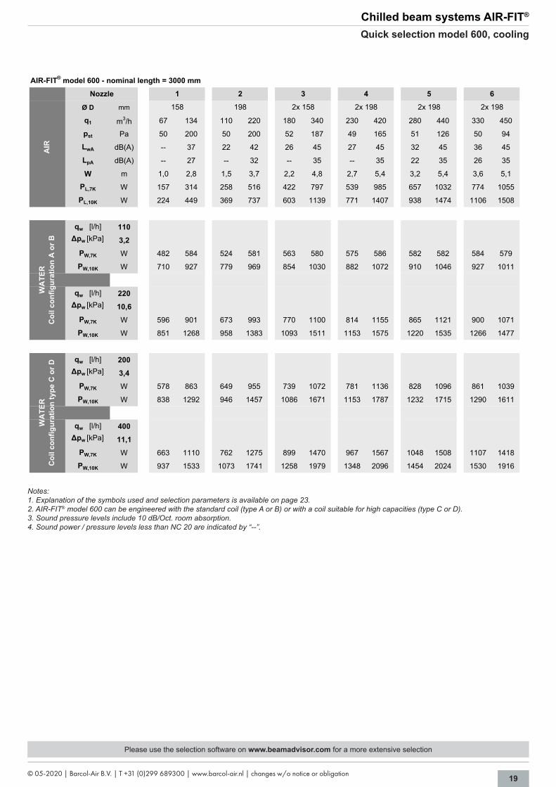
Quick selection model 600, cooling
AIR-FIT® model 600 - nominal length = 3000 mm
Ø D mm
q1 m3/h 67 134 110 220 180 340 230 420 280 440 330 450
pst Pa 50 200 50 200 52 187 49 165 51 126 50 94
LwA dB(A) -- 37 22 42 26 45 27 45 32 45 36 45
LpA dB(A) -- 27 -- 32 -- 35 -- 35 22 35 26 35
W m 1,0 2,8 1,5 3,7 2,2 4,8 2,7 5,4 3,2 5,4 3,6 5,1
PL,7K W 157 314 258 516 422 797 539 985 657 1032 774 1055
PL,10K W 224 449 369 737 603 1139 771 1407 938 1474 1106 1508
qw [l/h] 110∆pw [kPa] 3,2
PW,7K W 482 584 524 581 563 580 575 586 582 582 584 579
PW,10K W 710 927 779 969 854 1030 882 1072 910 1046 927 1011
qw [l/h] 220∆pw [kPa] 10,6
PW,7K W 596 901 673 993 770 1100 814 1155 865 1121 900 1071
PW,10K W 851 1268 958 1383 1093 1511 1153 1575 1220 1535 1266 1477
qw [l/h] 200∆pw [kPa] 3,4
PW,7K W 578 863 649 955 739 1072 781 1136 828 1096 861 1039
PW,10K W 838 1292 946 1457 1086 1671 1153 1787 1232 1715 1290 1611
qw [l/h] 400∆pw [kPa] 11,1
PW,7K W 663 1110 762 1275 899 1470 967 1567 1048 1508 1107 1418
PW,10K W 937 1533 1073 1741 1258 1979 1348 2096 1454 2024 1530 1916
2x 198 2x 198 2x 198
AIR
158 198 2x 158
5 64
WA
TER
Coi
l con
figur
atio
n ty
pe C
or D
1 2 3
WA
TER
Coi
l con
figur
atio
n A
or B
Nozzle
Please use the selection software on www.beamadvisor.com for a more extensive selection
Notes:1. Explanation of the symbols used and selection parameters is available on page 23.2. AIR-FIT® model 600 can be engineered with the standard coil (type A or B) or with a coil suitable for high capacities (type C or D).3. Sound pressure levels include 10 dB/Oct. room absorption.4. Sound power / pressure levels less than NC 20 are indicated by “--”.

20 © 05-2020 | Barcol-Air B.V. | T +31 (0)299 689300 | www.barcol-air.nl | changes w/o notice or obligation
Chilled beam systems AIR-FIT®
Quick selection model 600, heating
AIR-FIT® model 600 - nominal length = 600 mm
Ø D mm
m3/h 9 18 15 30 24 48 32 62 38 73 45 75
l/s 3 5 4 8 7 13 9 17 11 20 13 21
pst Pa 50 200 50 200 50 205 50 195 50 190 50 140
dB(A) -- 25 -- 29 -- 34 22 41 26 45 31 45
NC -- 20 -- 24 -- 29 -- 36 21 40 26 40
dB(A) -- -- -- -- -- 24 -- 31 -- 35 21 35
NC -- -- -- -- -- -- -- 26 -- 30 -- 30
PL,-3K W -10 -20 -15 -30 -25 -50 -30 -60 -40 -75 -45 -75
PL,-2K W -5 -10 -10 -20 -15 -30 -20 -40 -25 -50 -30 -50
qw [l/h] 50
∆pw [kPa] 0,4
PW,20K W 240 330 260 350 290 380 310 390 320 410 330 400
PW,35K W 410 600 460 660 520 710 560 740 580 760 600 750
qw [l/h] 100
∆pw [kPa] 1,2
PW,20K W 220 380 270 430 310 480 350 500 370 520 390 510
PW,35K W 380 690 470 770 560 860 620 910 660 940 690 920
WA
TER
Coi
l typ
e A
, B, C
of D
98 9898 98 98 98
AIR
Nozzle 61 2 3 4
q1
LwA
LpA
5
AIR-FIT® model 600 - nominal length = 1200 mm
Ø D mm
q1 m3/h 22 43 35 70 56 112 75 150 90 180 105 190
pst Pa 52 199 49 195 49 196 51 203 51 204 49 161
LwA dB(A) -- 32 -- 35 -- 35 -- 42 23 45 27 45
LpA dB(A) -- 22 -- 25 -- 25 -- 32 -- 35 -- 35
W m 1,1 1,8 1,2 2,2 1,5 2,8 1,8 3,4 2,0 3,8 2,2 3,7
PL,7K W 52 101 82 164 131 263 176 352 211 422 246 446
PL,10K W 74 144 117 235 188 375 251 503 302 603 352 637
qw [l/h] 90∆pw [kPa] 3,3
PW,7K W 183 284 204 309 235 336 257 353 272 365 282 361
PW,10K W 265 412 296 448 340 483 374 503 395 513 410 510
qw [l/h] 180∆pw [kPa] 10,6
PW,7K W 197 322 222 358 258 402 287 435 306 458 320 449
PW,10K W 284 464 320 515 372 575 413 618 441 647 460 636
qw [l/h] 180∆pw [kPa] 3,3
PW,7K W 210 341 236 379 274 426 304 463 324 490 338 480
PW,10K W 303 493 341 549 396 614 440 663 469 698 490 685
qw [l/h] 360∆pw [kPa] 10,6
PW,7K W 236 400 267 453 314 521 351 578 378 620 396 604
PW,10K W 338 573 383 647 450 740 504 814 541 867 568 848
158 158 158
AIR
98 123 158
5 64
WA
TER
Coi
l con
figur
atio
n ty
pe C
or D
1 2 3
WA
TER
Coi
l con
figur
atio
n A
or B
Nozzle
Please use the selection software on www.beamadvisor.com for a more extensive selection
Notes:1. Explanation of the symbols used and selection parameters is available on page 23.2. Sound pressure levels include 10 dB/Oct. room absorption.3. Sound power / pressure levels less than NC 20 are indicated by “--”.

21© 05-2020 | Barcol-Air B.V. | T +31 (0)299 689300 | www.barcol-air.nl | changes w/o notice or obligation
Chilled beam systems AIR-FIT®
Quick selection model 600, heating
AIR-FIT® model 600 - nominal length = 1500 mm
Ø D mm
m3/h 30 60 48 96 77 154 100 185 120 235 145 250
l/s 8 17 13 27 21 43 28 51 33 65 40 69
pst Pa 50 205 50 195 50 200 50 165 50 185 50 150
dB(A) -- 39 24 41 -- 40 26 45 25 45 30 45
NC -- 34 -- 36 -- 35 21 40 20 40 25 40
dB(A) -- 29 -- 31 -- 30 -- 35 -- 35 -- 35
NC -- 24 -- 26 -- 25 -- 30 -- 30 -- 30
PL,-3K W -30 -60 -50 -95 -75 -155 -100 -185 -120 -235 -145 -250
PL,-2K W -20 -40 -30 -65 -50 -105 -65 -125 -80 -155 -95 -170
qw [l/h] 50
∆pw [kPa] 0,7
PW,20K W 570 700 600 730 640 770 660 770 680 800 700 800
PW,35K W 1020 1280 1070 1330 1150 1410 1190 1430 1230 1480 1270 1470
qw [l/h] 100
∆pw [kPa] 2,2
PW,20K W 650 940 720 1010 800 1090 850 1110 890 1170 930 1160
PW,35K W 1190 1700 1310 1810 1460 1960 1540 1990 1610 2100 1680 2080
WA
TER
Coi
l typ
e A
, B, C
of D
198 19898 123 158 158
AIR
Nozzle 61 2 3 4
q1
LwA
LpA
5
AIR-FIT® model 600 - nominal length = 1800 mm
Ø D mm
m3/h 40 75 60 120 100 190 130 240 155 250 180 250
l/s 11 21 17 33 28 53 36 67 43 69 50 69
pst Pa 55 200 50 190 50 185 50 170 50 130 50 90
dB(A) 20 36 -- 35 25 45 27 45 32 45 35 45
NC -- 31 -- 30 20 40 22 40 27 40 30 40
dB(A) -- 26 -- 25 -- 35 -- 35 22 35 25 35
NC -- 21 -- 20 -- 30 -- 30 -- 30 20 30
PL,-3K W -40 -75 -60 -120 -100 -190 -130 -240 -155 -250 -180 -250
PL,-2K W -25 -50 -40 -80 -65 -125 -85 -160 -105 -170 -120 -170
qw [l/h] 50
∆pw [kPa] 0,8
PW,20K W 710 830 730 860 780 890 800 910 810 900 820 890
PW,35K W 1230 1470 1260 1540 1360 1610 1400 1640 1440 1630 1460 1590
qw [l/h] 100
∆pw [kPa] 2,5
PW,20K W 830 1110 870 1180 980 1260 1030 1300 1070 1280 1100 1240
PW,35K W 1460 1980 1530 2110 1730 2260 1830 2330 1900 2300 1950 2220
WA
TER
Coi
l typ
e A
, B, C
of D
200 200125 160 160 200
AIR
Nozzle 61 2 3 4
q1
LwA
LpA
5
Notes:1. Explanation of the symbols used and selection parameters is available on page 23.2. Sound pressure levels include 10 dB/Oct. room absorption.3. Sound power / pressure levels less than NC 20 are indicated by “--”.
Please use the selection software on www.beamadvisor.com for a more extensive selection

22 © 05-2020 | Barcol-Air B.V. | T +31 (0)299 689300 | www.barcol-air.nl | changes w/o notice or obligation
Chilled beam systems AIR-FIT®
Quick selection model 600, heating
AIR-FIT® model 600 - nominal length = 2400 mm
Ø D mm
m3/h 50 100 85 170 135 250 180 320 210 340 250 340
l/s 14 28 24 47 38 69 50 89 58 94 69 94
pst Pa 50 190 50 205 50 175 50 165 50 130 50 90
dB(A) 25 42 21 42 28 45 27 45 30 45 35 45
NC 20 37 -- 37 23 40 22 40 25 40 30 40
dB(A) -- 32 -- 32 -- 35 -- 35 20 35 25 35
NC -- 27 -- 27 -- 30 -- 30 -- 30 20 30
PL,-3K W -50 -100 -85 -170 -135 -250 -180 -320 -210 -340 -250 -340
PL,-2K W -35 -65 -55 -115 -90 -170 -120 -215 -140 -230 -170 -230
qw [l/h] 50
∆pw [kPa] 1,0
PW,20K W 760 910 810 960 850 990 880 1010 900 1010 920 990
PW,35K W 1390 1650 1470 1740 1540 1780 1600 1820 1630 1810 1660 1780
qw [l/h] 100
∆pw [kPa] 3,3
PW,20K W 1000 1340 1100 1450 1200 1510 1270 1560 1310 1550 1350 1500
PW,35K W 1770 2390 1960 2580 2140 2680 2260 2780 2320 2750 2400 2670
198
Nozzle 1 2 3
WA
TER
Coi
l typ
e A
, B, C
of D
AIR
123 158
q1
LwA
LpA
4 5 6
2x 158 2x 158 2x 158
AIR-FIT® model 600 - nominal length = 3000 mm
Ø D mm
m3/h 67 134 110 220 180 340 230 420 280 440 330 450
l/s 19 37 31 61 50 94 64 117 78 122 92 125
pst Pa 50 200 50 200 50 185 50 165 50 125 50 95
dB(A) -- 37 22 42 26 45 27 45 32 45 36 45
NC -- 32 -- 37 21 40 22 40 27 40 31 40
dB(A) -- 27 -- 32 -- 35 -- 35 22 35 26 35
NC -- 22 -- 27 -- 30 -- 30 -- 30 21 30
PL,-3K W -65 -135 -110 -220 -180 -340 -230 -420 -280 -440 -330 -450
PL,-2K W -45 -90 -75 -145 -120 -230 -155 -280 -190 -295 -220 -300
qw [l/h] 50
∆pw [kPa] 1,2
PW,20K W 880 1030 920 1070 970 1110 990 1120 1020 1120 1030 1100
PW,35K W 1550 1850 1630 1930 1720 2000 1770 2030 1820 2010 1850 1980
qw [l/h] 100
∆pw [kPa] 4,0
PW,20K W 1190 1560 1290 1660 1410 1750 1460 1780 1520 1760 1560 1730
PW,35K W 2110 2790 2290 2970 2510 3130 2610 3190 2710 3160 2790 3090
WA
TER
Coi
l typ
e A
, B, C
of D
Nozzle 5 61 2 3 4
2x 198 2x 198 2x 198
AIR
158 198 2x 158
q1
LwA
LpA
Please use the selection software on www.beamadvisor.com for a more extensive selection
Notes:1. Explanation of the symbols used and selection parameters is available on page 23.2. Sound pressure levels include 10 dB/Oct. room absorption.3. Sound power / pressure levels less than NC 20 are indicated by “--”.

23© 05-2020 | Barcol-Air B.V. | T +31 (0)299 689300 | www.barcol-air.nl | changes w/o notice or obligation
Chilled beam systems AIR-FIT®
Parameters quick selection / airside connections
Used symbols
ØD Air inlet diameter plenum mm q1 Primaryairflow m3/h - l/spst Static pressure plenum Pa LwA Sound power level dB(A) LpA Sound pressure level dB(A) W Throw m qw Waterflow l/h Δpw Waterside pressure drop of the coil kPa PL,7K Aircoolingcapacityatatemperaturedifferenceof7K(Troom - T1=7K) WPL,K Aircoolingcapacityatatemperaturedifferenceof10K(Troom - T1=10K) W PW,7K Watercoolingcapacityatatemperaturedifferenceof7K(Troom - Twater,in=7K) W PW,10KWatercoolingcapacityatatemperaturedifferenceof10K(Troom - Twater,in=10K) W
Parameters quick selection Discharge pattern 2-sided Room height 2,7 - 3,0 mLpA maximum 35 / 30 dB(A) / NCRoom attenuation LpA values 10 dB / Octpst maximum 50 - 200 PaΔpw maximum 11 kPa
Model 300 - top connection, side connection or reduced height with side connection
ØDLength A B C D E F G H
600 98 98 98 98 98 98 98 981200 98 98 98 123 123 123 98 1231500 98 98 123 123 158 158 123 1581800 98 123 123 158 158 158 123 1582400 123 123 158 158 198 198 158 1983000 123 158 158 198 198 198 158 198
Nozzle bar configuration
Model 600 - top connection or side connection
ØDLength A B C D E F G H
600 98 98 98 98 98 98 98 981200 98 123 158 158 158 158 158 1581500 98 123 158 158 198 198 158 1981800 123 158 158 198 198 198 158 1982400 123 158 198 2 x 158 2 x 158 2 x 158 198 2 x 1583000 158 198 2 x 158 2 x 198 2 x 198 2 x 198 2 x 158 2 x 198
Nozzle bar configuration

24 © 05-2020 | Barcol-Air B.V. | T +31 (0)299 689300 | www.barcol-air.nl | changes w/o notice or obligation
A
Chilled beam systems AIR-FIT®
Installation / adjustable nozzle types
Installation
The unit has 7 mm diameter hanging brackets for easy installation. These can be used to connect the unit to the ceiling construction.
The width (295 or 595 mm) is suitable for T-bar ceilingswith300or600mmcentretocentredimensions. Ensure dimensions in other type ceilings are adapted.
Extra care shall be taken on the airside and waterside connections (top, left or right side). The installation method should be suitable for the weight of the unit.
Remark:Please note that all controls must be accessible at all time. During installation this must be taken in consideration. Furthermore, all units must be installed in a clean, dust free and dry environment.
Installation method model 300
Adjustable nozzle types
When an active chilled beam AIR-FIT® is selected,astandardfixednozzletypeisrequired.
Optionally an adjustable unit with two nozzle types can be choosen. The required nozzle type is set ex works. By using an adjustable sliding plate, the nozzle type can be altered subse-quently.
Adjusting nozzle typesThe only tool needed to adjust the nozzle type is a Philips head (cross-slotted) screwdriver.
Step 1: Remove the front panel (A, B, C):
Step 2: Unscrew all screws from the sliding plate (1 full turn):
Step 3: Move the sliding plate into the desired position.
Step 4: Thighten all screws (hand tight).
Step 5: Replace the front panel.
Adjustable nozzle types
AB
C
Installationmethodmodel600

25© 05-2020 | Barcol-Air B.V. | T +31 (0)299 689300 | www.barcol-air.nl | changes w/o notice or obligation
Chilled beam systems AIR-FIT®
Waterside connections
Example of the copper connections of the reheat coil, model 300. The copper tube con-nection has a minimum length of 40 mm.
Optionally:Flexible hoses (diffuse leakproof till 80 °C), with stainless steel sleeve. The hose is on both sides equipped with a quick-release connection with securing clip.
Note:The copper tubing needs to be free of any damage and completely circular for a leak proof connection.When installing please take in to consideration that the material will shrink and expand.
Note:1. The tolerance on the diameter copper connection of the copper heating/cooling coil is ± 0,15 mm.
Dimensional data connections
Width 300 / 600
Model 600 - 1800 2400 - 3000
Ødcold 12 15
Ødhot 12
==
125
56
cooling IN
heating IN*
cooling OUTheating OUT*
* only 4-pipes
MODEL 300 MODEL 600
==
9743
cooling IN
heating IN*
cooling OUTheating OUT*
* only 4-pipes

BARCOL-AIR | AIR DISTRIBUTIONCantekoogweg 10-12 - 1442 LG Purmerend, The NetherlandsT+31(0)299689300| E [email protected]
OUR TECHNOLOGY | YOUR WELLBEING
WWW.BARCOL-AIR.NL