Embed Size (px)
Citation preview

1
NCC Ost
NürnbergMesse, Arbeitstitel, Datum
Chillventa CONGRESS 2018
INDUSTRIAL HEAT PUMPS IN AUSTRIA Current status and future potentials
V. Wilk, A. Arnitz, R. Rieberer
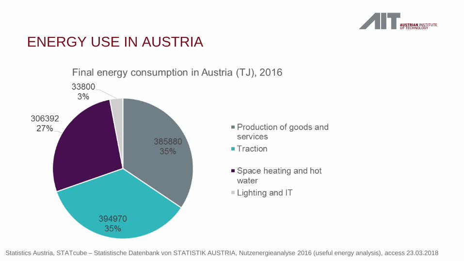
ENERGY USE IN AUSTRIA
Statistics Austria, STATcube – Statistische Datenbank von STATISTIK AUSTRIA, Nutzenergieanalyse 2016 (useful energy analysis), access 23.03.2018

Dairy
FOOD INDUSTRY
• Berglandmilch eGen / Tirol Milch Wörgl • Joint project with Stadtwerke Wörgl • Installed by Frigopol in 2015
3 heat pumps with a total • cooling capacity: 2070 kW • heating capacity: 2750 kW
• Heat source: chillers, up to 45°C • Heat sink: 78°C, for district heating
4 08/11/2018 Photo: Frigopol Hochtemperatur-Wärmepumpen, http://www.frigopol.com/wp-content/uploads/54b8ce0cdfdd6.pdf
Further details: A. Baumhakel, Frigopol Kälteanlagen GmbH, www.frigopol.com
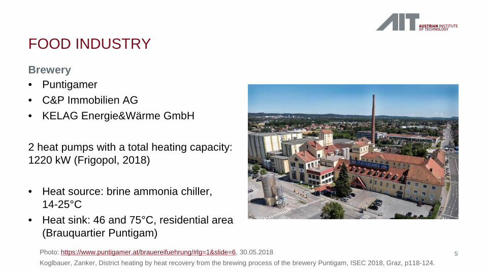
Brewery
FOOD INDUSTRY
• Puntigamer • C&P Immobilien AG • KELAG Energie&Wärme GmbH
2 heat pumps with a total heating capacity: 1220 kW (Frigopol, 2018)
• Heat source: brine ammonia chiller,
14-25°C • Heat sink: 46 and 75°C, residential area
(Brauquartier Puntigam) 5 Photo: https://www.puntigamer.at/brauereifuehrung/#lg=1&slide=6, 30.05.2018
Koglbauer, Zanker, District heating by heat recovery from the brewing process of the brewery Puntigam, ISEC 2018, Graz, p118-124.
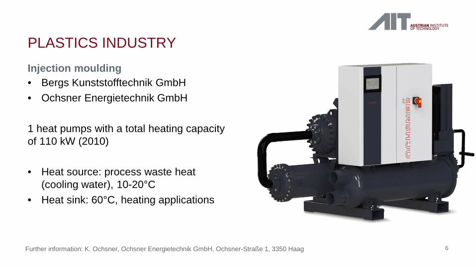
Injection moulding
PLASTICS INDUSTRY
• Bergs Kunststofftechnik GmbH • Ochsner Energietechnik GmbH
1 heat pumps with a total heating capacity of 110 kW (2010)
• Heat source: process waste heat
(cooling water), 10-20°C • Heat sink: 60°C, heating applications
6 Further information: K. Ochsner, Ochsner Energietechnik GmbH, Ochsner-Straße 1, 3350 Haag
7 08.11.2018
Heat sources: • waste water: 20 – 40°C, also contaminated • off gas : 60 – 80°C, high humidity, contaminated • waste heat from chillers: ca. 30°C • waste heat from process cooling (cooling water): ca. 50°C
Heat demand: • process water: 50 – 80°C • steam: 105 – 210°C • air preheating, feed water preheating Capacity: • up to the MW range
WHERE TO USE A HEAT PUMP IN INDUSTRY?
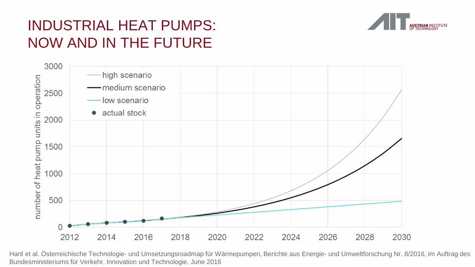
INDUSTRIAL HEAT PUMPS: NOW AND IN THE FUTURE
Hartl et al. Österreichische Technologie- und Umsetzungsroadmap für Wärmepumpen, Berichte aus Energie- und Umweltforschung Nr. 8/2016, im Auftrag des Bundesministeriums für Verkehr, Innovation und Technologie, June 2016
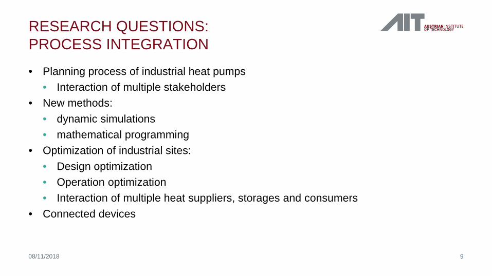
• Planning process of industrial heat pumps • Interaction of multiple stakeholders
• New methods: • dynamic simulations • mathematical programming
• Optimization of industrial sites: • Design optimization • Operation optimization • Interaction of multiple heat suppliers, storages and consumers
• Connected devices
RESEARCH QUESTIONS: PROCESS INTEGRATION
9 08/11/2018
Industrial Heat Pump Applications in Japan
Takenobu KAIDA Central Research Institute of Electric Power Industry (CRIEPI)
Chillventa CONGRESS 2018 Nuremberg, Germany
October 15, 2018
©CRIEPI
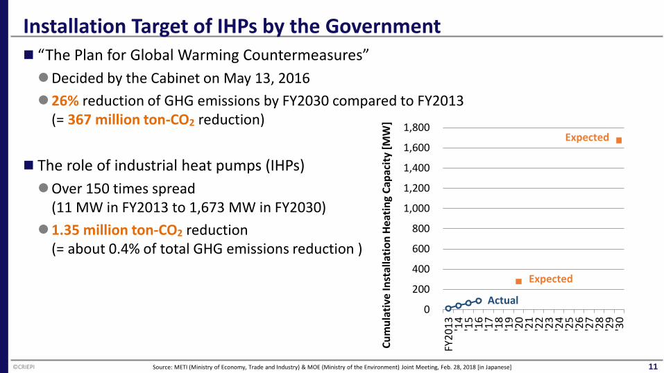
Installation Target of IHPs by the Government
11
“The Plan for Global Warming Countermeasures” Decided by the Cabinet on May 13, 2016 26% reduction of GHG emissions by FY2030 compared to FY2013
(= 367 million ton-CO2 reduction)
The role of industrial heat pumps (IHPs) Over 150 times spread
(11 MW in FY2013 to 1,673 MW in FY2030) 1.35 million ton-CO2 reduction
(= about 0.4% of total GHG emissions reduction )
0
200
400
600
800
1,000
1,200
1,400
1,600
1,800
FY20
13 '14
'15
'16
'17
'18
'19
'20
'21
'22
'23
'24
'25
'26
'27
'28
'29
'30
Expected
Actual
Expected
Cum
ulat
ive
Inst
alla
tion
Heat
ing
Capa
city
[MW
]
Source: METI (Ministry of Economy, Trade and Industry) & MOE (Ministry of the Environment) Joint Meeting, Feb. 28, 2018 [in Japanese]
©CRIEPI
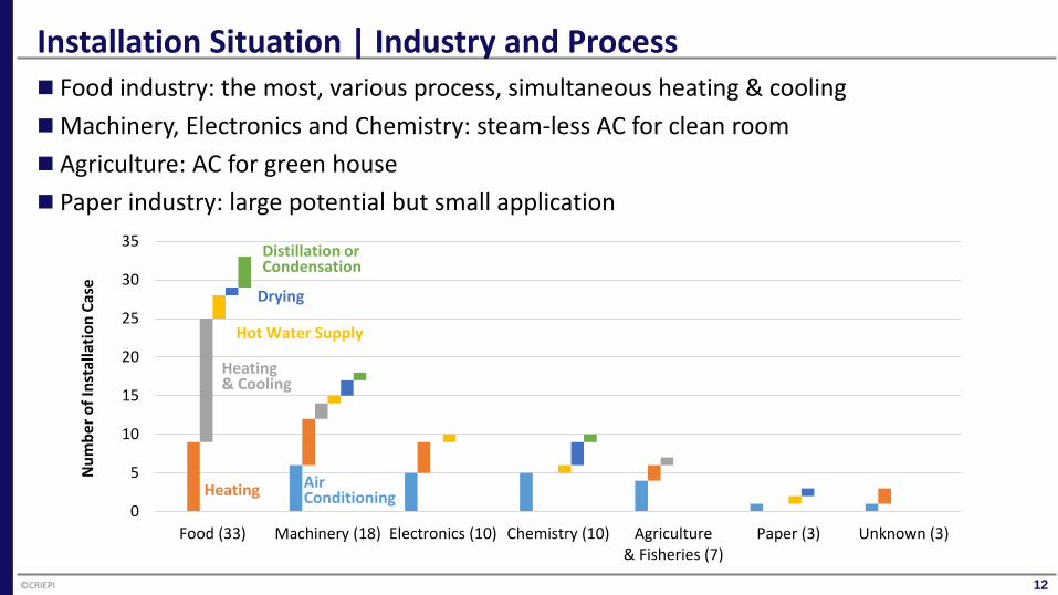
Installation Situation | Industry and Process
12
Food industry: the most, various process, simultaneous heating & cooling Machinery, Electronics and Chemistry: steam-less AC for clean room Agriculture: AC for green house Paper industry: large potential but small application
0
5
10
15
20
25
30
35
Food (33) Machinery (18) Electronics (10) Chemistry (10) Agriculture& Fisheries (7)
Paper (3) Unknown (3)
Num
ber o
f Ins
talla
tion
Case
Heating
Heating& Cooling
Hot Water Supply
Drying
Distillation or Condensation
Air Conditioning
©CRIEPI
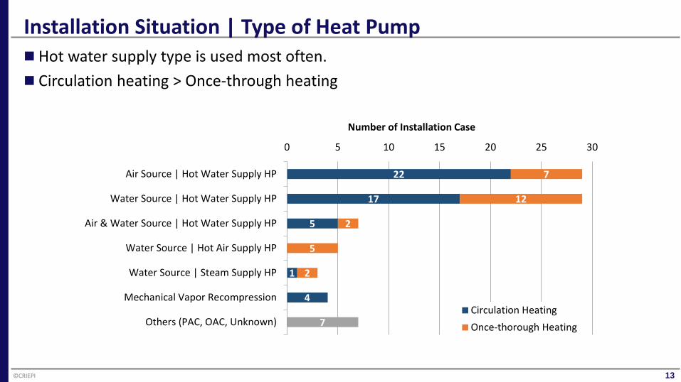
Installation Situation | Type of Heat Pump
13
Hot water supply type is used most often. Circulation heating > Once-through heating
22
17
5
1
4
7
7
12
2
5
2
0 5 10 15 20 25 30
Air Source | Hot Water Supply HP
Water Source | Hot Water Supply HP
Air & Water Source | Hot Water Supply HP
Water Source | Hot Air Supply HP
Water Source | Steam Supply HP
Mechanical Vapor Recompression
Others (PAC, OAC, Unknown)
Number of Installation Case
Circulation HeatingOnce-thorough Heating
©CRIEPI
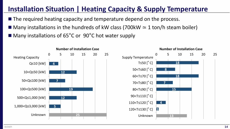
Installation Situation | Heating Capacity & Supply Temperature
14
The required heating capacity and temperature depend on the process. Many installations in the hundreds of kW class (700kW ≃ 1 ton/h steam boiler) Many installations of 65°C or 90°C hot water supply
4
12
7
19
12
5
25
0 5 10 15 20 25
Q≤10 [kW]
10<Q≤50 [kW]
50<Q≤100 [kW]
100<Q≤500 [kW]
500<Q≤1,000 [kW]
1,000<Q≤3,000 [kW]
Unknown
Number of Installation Case
Heating Capacity18
8
18
7
15
0
4
1
13
0 5 10 15 20 25
T≤50 [°C]
50<T≤60 [°C]
60<T≤70 [°C]
70<T≤80 [°C]
80<T≤90 [°C]
90<T≤110 [°C]
110<T≤120 [°C]
120<T≤130 [°C]
Unknown
Number of Installation Case
Supply Temperature
©CRIEPI
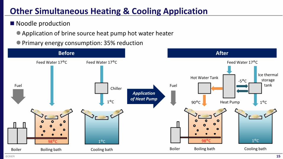
Other Simultaneous Heating & Cooling Application
15
Noodle production Application of brine source heat pump hot water heater Primary energy consumption: 35% reduction
Boiler Boiling bath Cooling bath
98°C 1°C
Boiler Boiling bath Cooling bath
98°C 1°C
Fuel Fuel
Feed Water 17°C Feed Water 17°C
Chiller
1°C
Feed Water 17°C
-5°C
1°C 90°C Heat Pump
Hot Water Tank Ice thermal
storage tank
Before
Application of Heat Pump
After
©CRIEPI
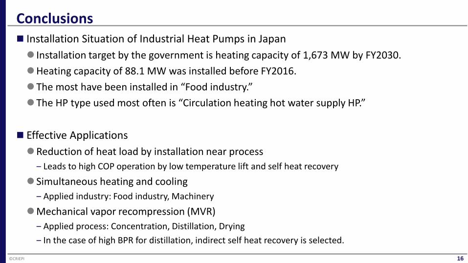
Conclusions
16
Installation Situation of Industrial Heat Pumps in Japan Installation target by the government is heating capacity of 1,673 MW by FY2030. Heating capacity of 88.1 MW was installed before FY2016. The most have been installed in “Food industry.” The HP type used most often is “Circulation heating hot water supply HP.”
Effective Applications Reduction of heat load by installation near process
‒ Leads to high COP operation by low temperature lift and self heat recovery
Simultaneous heating and cooling ‒ Applied industry: Food industry, Machinery
Mechanical vapor recompression (MVR) ‒ Applied process: Concentration, Distillation, Drying ‒ In the case of high BPR for distillation, indirect self heat recovery is selected.
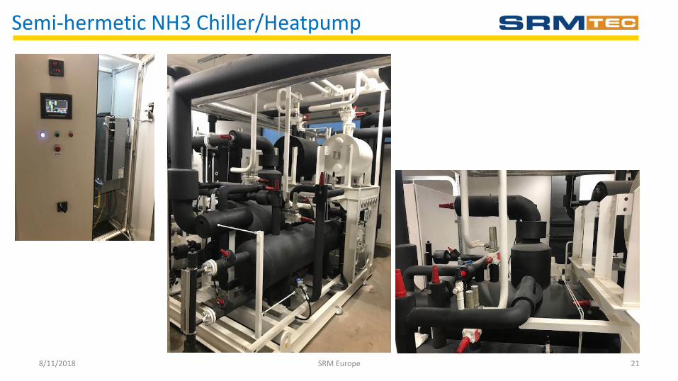
Semi-hermetic NH3 Chiller/Heatpump
• Introduction of SRM • Project
– Objective – Technical Solution – Summary and Conclusion
Agenda
8/11/2018 17
Semi-hermetic NH3 Chiller/Heatpump
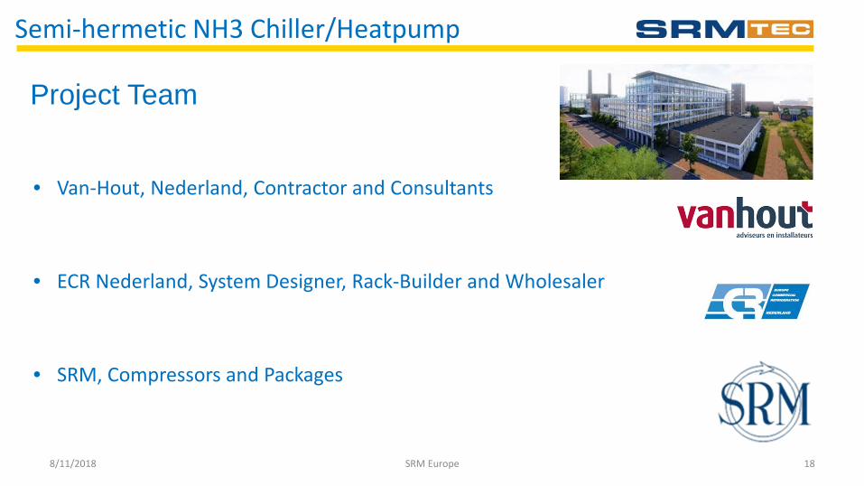
• Van-Hout, Nederland, Contractor and Consultants
• ECR Nederland, System Designer, Rack-Builder and Wholesaler
• SRM, Compressors and Packages
8/11/2018 18
Project Team
SRM Europe
Semi-hermetic NH3 Chiller/Heatpump
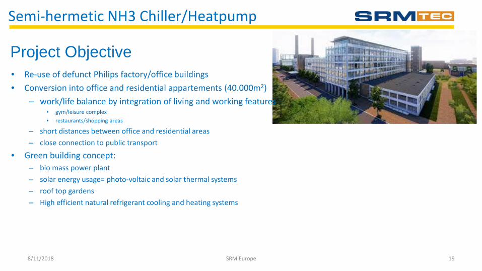
• Re-use of defunct Philips factory/office buildings • Conversion into office and residential appartements (40.000m2)
– work/life balance by integration of living and working features • gym/leisure complex • restaurants/shopping areas
– short distances between office and residential areas – close connection to public transport
• Green building concept: – bio mass power plant – solar energy usage= photo-voltaic and solar thermal systems – roof top gardens – High efficient natural refrigerant cooling and heating systems
8/11/2018 19
Project Objective
SRM Europe
Semi-hermetic NH3 Chiller/Heatpump
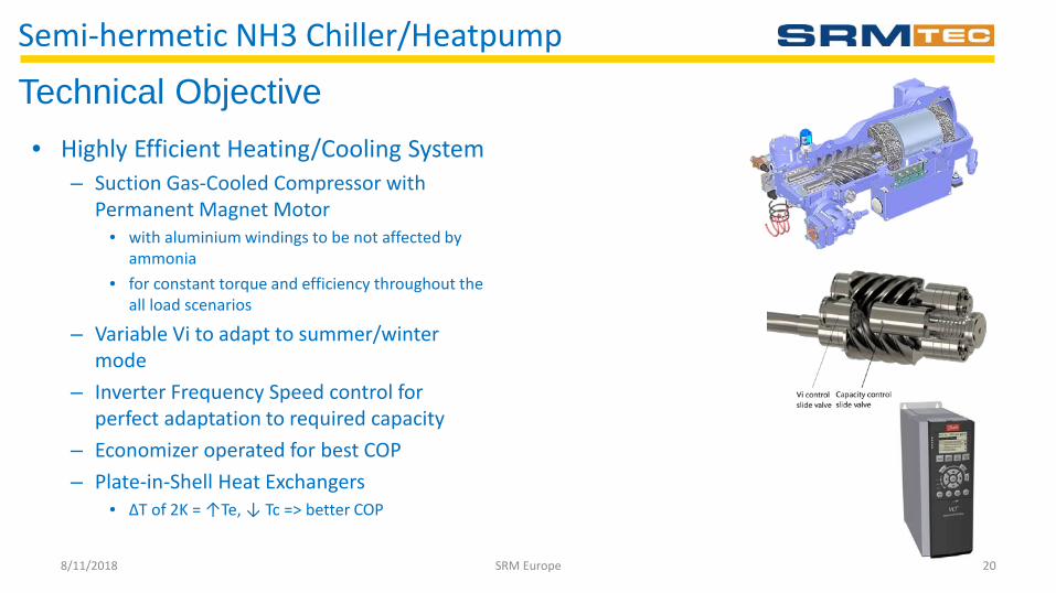
• Highly Efficient Heating/Cooling System – Suction Gas-Cooled Compressor with
Permanent Magnet Motor • with aluminium windings to be not affected by
ammonia • for constant torque and efficiency throughout the
all load scenarios
– Variable Vi to adapt to summer/winter mode
– Inverter Frequency Speed control for perfect adaptation to required capacity
– Economizer operated for best COP – Plate-in-Shell Heat Exchangers
• ΔT of 2K = ↑Te, ↓ Tc => better COP
8/11/2018 20
Technical Objective
SRM Europe
Semi-hermetic NH3 Chiller/Heatpump
8/11/2018 21 SRM Europe
Decreasing energy consumption of heating and air conditioning system with energy-efficient heat pump
combined with natural energy
Xianting Li Department of building science
Tsinghua University 2018/11/8
Chillventa International Exhibition, Nuremberg
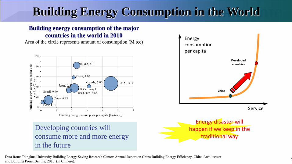
Building Energy Consumption in the World
Data from: Tsinghua University Building Energy Saving Research Center: Annual Report on China Building Energy Efficiency, China Architecture and Building Press, Beijing, 2015 (in Chinese).
Service
China
Developed countries
Energy consumption per capita
Energy disaster will happen if we keep in the
traditional way
Building energy consumption of the major countries in the world in 2010
Area of the circle represents amount of consumption (M tce)
Developing countries will consume more and more energy in the future
8
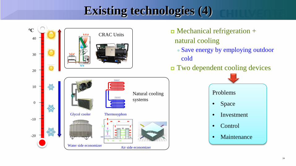
24
℃
-10
-20
0
10
20
30
40
Mechanical refrigeration + natural cooling Save energy by employing outdoor
cold Two dependent cooling devices
CRAC Units
Glycol cooler Thermosyphon
Water side economizer Air side economizer
Natural cooling systems
Problems
• Space
• Investment
• Control
• Maintenance
Existing technologies (4)
25
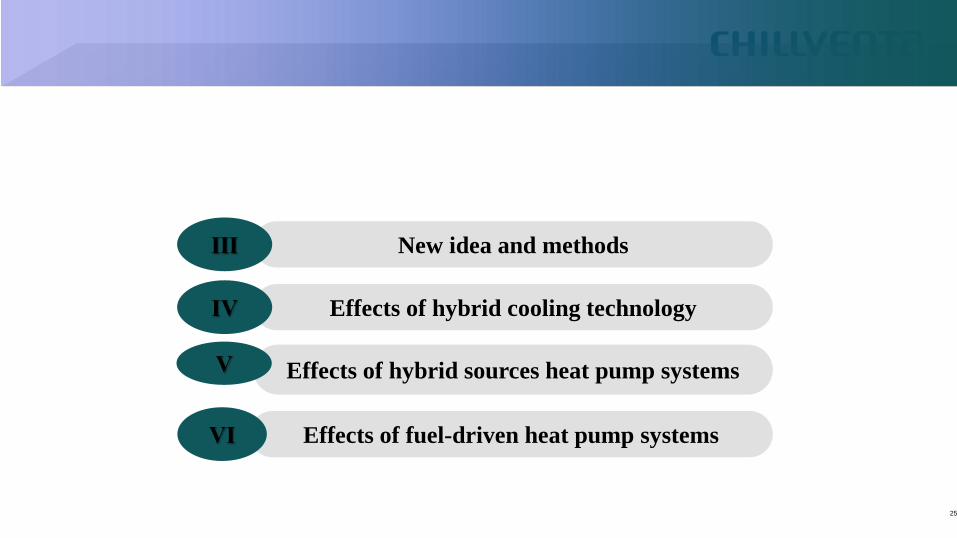
New idea and methods Ⅲ
Effects of hybrid cooling technology Ⅳ
Effects of hybrid sources heat pump systems Ⅴ
Effects of fuel-driven heat pump systems Ⅵ
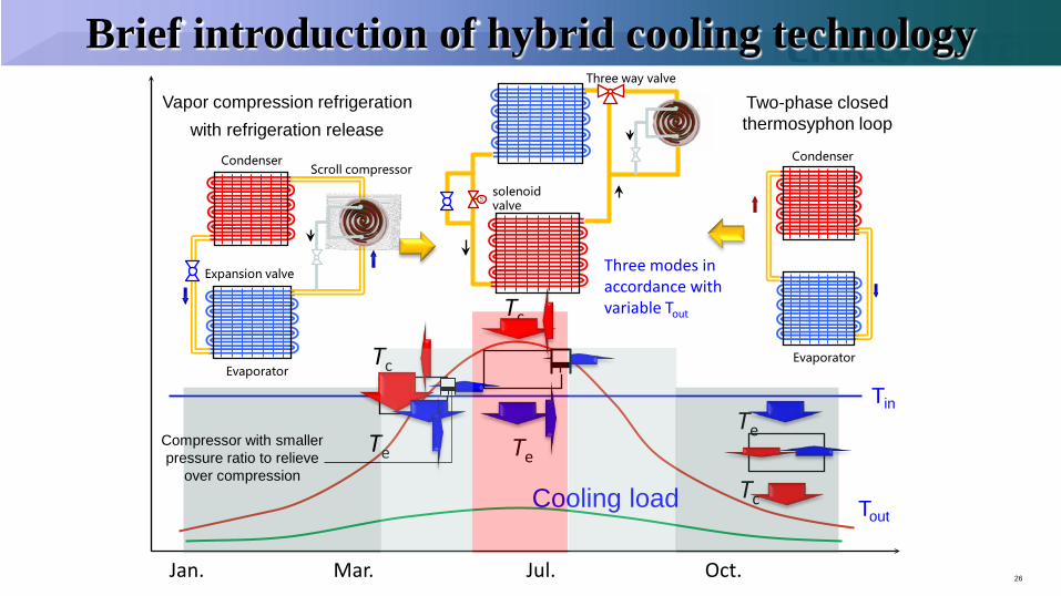
Brief introduction of hybrid cooling technology
26
Tin
Tout Cooling load
Jan. Mar. Jul. Oct.
Te
Tc
Te
Tc
Two-phase closed thermosyphon loop
Condenser
Evaporator
Vapor compression refrigeration
Scroll compressor Condenser
Evaporator
Expansion valve
with refrigeration release
Te
Tc
Compressor with smaller pressure ratio to relieve
over compression
S
Three way valve
solenoid valve
Three modes in accordance with variable Tout
VII. Summary It is important to decrease the energy usage for heating and air conditioning The load grading provide a way for more natural energy usage and more period
for efficient heat pump in different climate. Making full use of natural energy can help heat pump play a great role in clean
heating and efficient air conditioning. Natural energy can be used combined with heat pump, like hybrid cooling technology Different kinds of natural energy can also be used in the way of hybrid sources heat pump so
that the efficiency and reliability of heat pump can be improved When natural energy is combined with fuel-drive absorption heat pump, the primary energy
efficiency of hot water will be improved a lot.
52
Revisiting R22 Replacement Options Comparison between R-22, R-404A, R-448A, R-407A and R-407H
Authors: Ivan Rydkin – Daikin America Hitomi Arimoto, Shun Ohkubo – Daikin Industries Matej Visek, Xinzhong Li, Pega Hrnjak – Creative Thermal Solutions
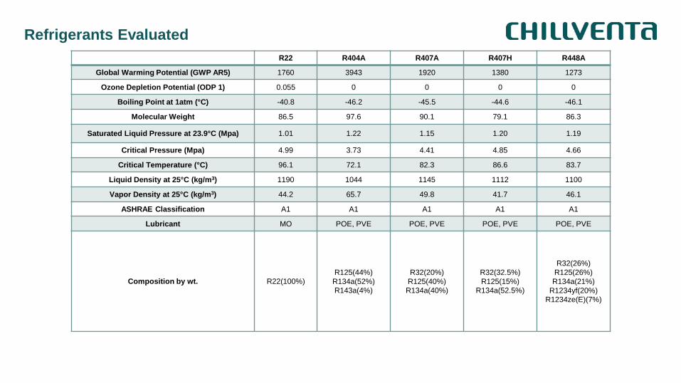
Refrigerants Evaluated R22 R404A R407A R407H R448A
Global Warming Potential (GWP AR5) 1760 3943 1920 1380 1273
Ozone Depletion Potential (ODP 1) 0.055 0 0 0 0
Boiling Point at 1atm (°C) -40.8 -46.2 -45.5 -44.6 -46.1
Molecular Weight 86.5 97.6 90.1 79.1 86.3
Saturated Liquid Pressure at 23.9°C (Mpa) 1.01 1.22 1.15 1.20 1.19
Critical Pressure (Mpa) 4.99 3.73 4.41 4.85 4.66
Critical Temperature (°C) 96.1 72.1 82.3 86.6 83.7
Liquid Density at 25°C (kg/m3) 1190 1044 1145 1112 1100
Vapor Density at 25°C (kg/m3) 44.2 65.7 49.8 41.7 46.1
ASHRAE Classification A1 A1 A1 A1 A1
Lubricant MO POE, PVE POE, PVE POE, PVE POE, PVE
Composition by wt. R22(100%) R125(44%) R134a(52%) R143a(4%)
R32(20%) R125(40%) R134a(40%)
R32(32.5%) R125(15%)
R134a(52.5%)
R32(26%) R125(26%) R134a(21%)
R1234yf(20%) R1234ze(E)(7%)
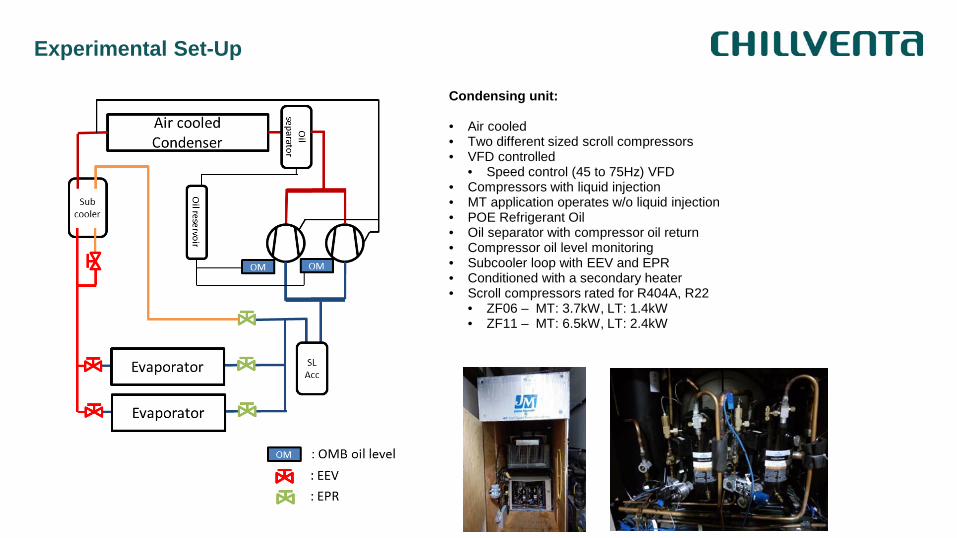
Experimental Set-Up
Condensing unit: • Air cooled • Two different sized scroll compressors • VFD controlled
• Speed control (45 to 75Hz) VFD • Compressors with liquid injection • MT application operates w/o liquid injection • POE Refrigerant Oil • Oil separator with compressor oil return • Compressor oil level monitoring • Subcooler loop with EEV and EPR • Conditioned with a secondary heater • Scroll compressors rated for R404A, R22
• ZF06 – MT: 3.7kW, LT: 1.4kW • ZF11 – MT: 6.5kW, LT: 2.4kW
Experimental Set-Up
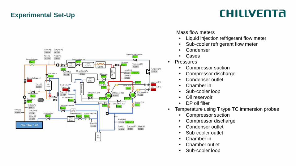
Mass flow meters • Liquid injection refrigerant flow meter • Sub-cooler refrigerant flow meter • Condenser • Cases
• Pressures • Compressor suction • Compressor discharge • Condenser outlet • Chamber in • Sub-cooler loop • Oil reservoir • DP oil filter
• Temperature using T type TC immersion probes • Compressor suction • Compressor discharge • Condenser outlet • Sub-cooler outlet • Chamber in • Chamber outlet • Sub-cooler loop
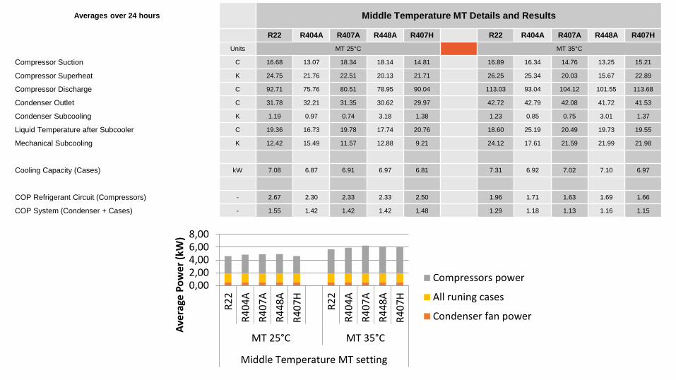
Medium Temperature Averages over 24 hours Middle Temperature MT Details and Results
R22 R404A R407A R448A R407H R22 R404A R407A R448A R407H
Units MT 25°C MT 35°C
Compressor Suction C 16.68 13.07 18.34 18.14 14.81 16.89 16.34 14.76 13.25 15.21
Compressor Superheat K 24.75 21.76 22.51 20.13 21.71 26.25 25.34 20.03 15.67 22.89
Compressor Discharge C 92.71 75.76 80.51 78.95 90.04 113.03 93.04 104.12 101.55 113.68
Condenser Outlet C 31.78 32.21 31.35 30.62 29.97 42.72 42.79 42.08 41.72 41.53
Condenser Subcooling K 1.19 0.97 0.74 3.18 1.38 1.23 0.85 0.75 3.01 1.37
Liquid Temperature after Subcooler C 19.36 16.73 19.78 17.74 20.76 18.60 25.19 20.49 19.73 19.55
Mechanical Subcooling K 12.42 15.49 11.57 12.88 9.21 24.12 17.61 21.59 21.99 21.98
Cooling Capacity (Cases) kW 7.08 6.87 6.91 6.97 6.81 7.31 6.92 7.02 7.10 6.97
COP Refrigerant Circuit (Compressors) - 2.67 2.30 2.33 2.33 2.50 1.96 1.71 1.63 1.69 1.66
COP System (Condenser + Cases) - 1.55 1.42 1.42 1.42 1.48 1.29 1.18 1.13 1.16 1.15
0,002,004,006,008,00
R22
R404
AR4
07A
R448
AR4
07H
R22
R404
AR4
07A
R448
AR4
07H
MT 25°C MT 35°C
Middle Temperature MT setting
Aver
age
Pow
er (k
W)
Compressors power
All runing cases
Condenser fan power
Summary
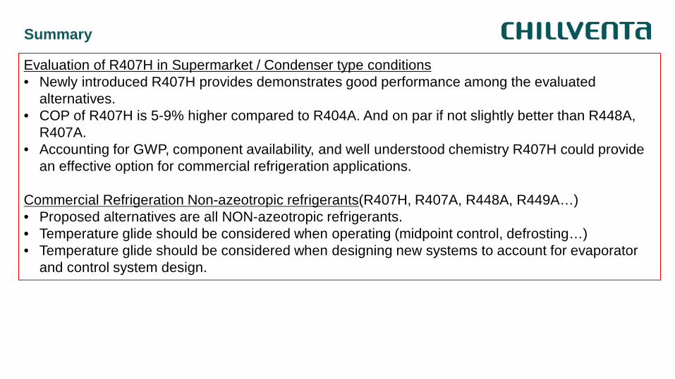
Evaluation of R407H in Supermarket / Condenser type conditions • Newly introduced R407H provides demonstrates good performance among the evaluated
alternatives. • COP of R407H is 5-9% higher compared to R404A. And on par if not slightly better than R448A,
R407A. • Accounting for GWP, component availability, and well understood chemistry R407H could provide
an effective option for commercial refrigeration applications. Commercial Refrigeration Non-azeotropic refrigerants(R407H, R407A, R448A, R449A…) • Proposed alternatives are all NON-azeotropic refrigerants. • Temperature glide should be considered when operating (midpoint control, defrosting…) • Temperature glide should be considered when designing new systems to account for evaporator
and control system design.

ulster.ac.uk
Heat Pumping Technologies for Commercial and Industrial Applications
Professor Neil J Hewitt
Lecture was not presented
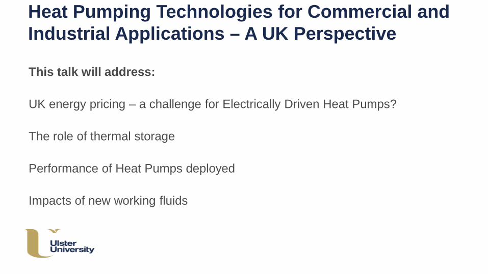
Heat Pumping Technologies for Commercial and Industrial Applications – A UK Perspective
This talk will address: UK energy pricing – a challenge for Electrically Driven Heat Pumps? The role of thermal storage Performance of Heat Pumps deployed Impacts of new working fluids
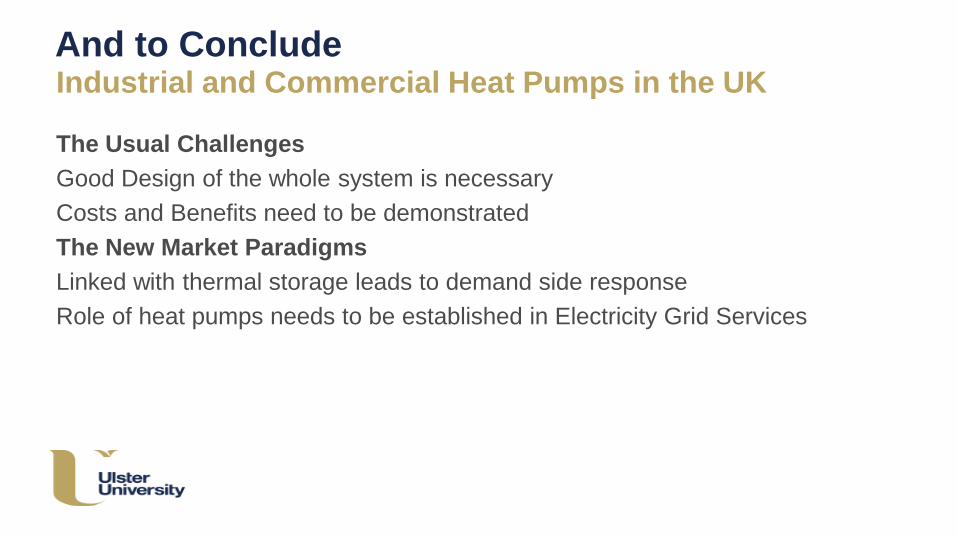
And to Conclude Industrial and Commercial Heat Pumps in the UK
The Usual Challenges Good Design of the whole system is necessary Costs and Benefits need to be demonstrated The New Market Paradigms Linked with thermal storage leads to demand side response Role of heat pumps needs to be established in Electricity Grid Services
High Temperature Heat Pumps 1) Market & Research Status, Refrigerants, Application Potentials 2) Results with a laboratory-scale heat pump using HCFO R1233zd Cordin Arpagaus1, Frédéric Bless1, Michael Uhlmann1, Elias Büchel1, Stefan Frei1, Jürg Schiffmann2, Stefan S. Bertsch1
1 NTB University of Applied Sciences of Technology Buchs, Switzerland 2 Ecole Polytechnique Fédérale de Lausanne, Switzerland
Chillventa, 15 October 2018, Nurenberg 1 [email protected]
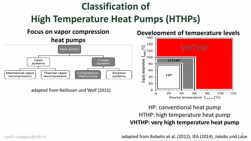
Classification of High Temperature Heat Pumps (HTHPs)
HP: conventional heat pump HTHP: high temperature heat pump
VHTHP: very high temperature heat pump
adapted from Bobelin et al. (2012), IEA (2014), Jakobs und Laue (2015) P l (2012 2014)
Development of temperature levels
adapted from Nellissen und Wolf (2015)
Focus on vapor compression heat pumps
VHTHP
16
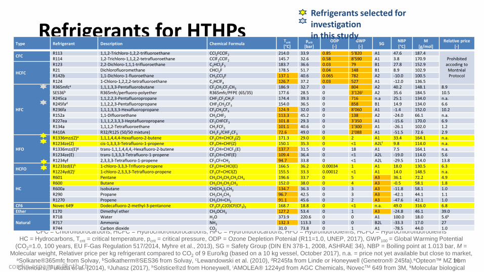
Refrigerants for HTHPs
CFC = Chlorofluorocarbons, HCFC = Hydrochlorofluorocarbons, HFC = Hydrofluorocarbons, HFO = Hydrofluoroolefins, HCFO = Hydrochlorofluoroolefins HC = Hydrocarbons, Tcrit = critical temperature, pcrit = critical pressure, ODP = Ozone Depletion Potenial (R11=1.0, UNEP, 2017), GWP100 = Global Warming Potential
(CO2=1.0, 100 years, EU F-Gas Regulation 517/2014, Myhre et al., 2013), SG = Safety Group (DIN EN 378-1, 2008, ASHRAE 34), NBP = Boiling point at 1.013 bar, M = Molecular weight, Relativer price per kg refrigerant compared to CO2 of 9 Euro/kg (based on a 10 kg vessel, October 2017), n.a. = price not yet available but close to market,
aSolkane®365mfc from Solvay, bSolkatherm®SES36 from Solvay, cLewandowski et al. (2010), dR245fa from Linde or Honeywell (Genetron® 245fa).eOpteon™ MZ from Chemours, fFukuda et al. (2014), gJuhasz (2017), hSolstice®zd from Honeywell, iAMOLEA® 1224yd from AGC Chemicals, jNovecTM 649 from 3M, kMolecular biological
Type Refrigerant Description Chemical Formula Tcrit [°C]
pcrit [bar]
ODP [-]
GWP [-] SG NBP
[°C] M
[g/mol] Relative price
[-]
CFC R113 1,1,2-Trichloro-1,2,2-trifluoroethane CCl2FCClF2 214.0 33.9 0.85 5‘820 A1 47.6 187.4 Prohibited
accoding to Montréal Protocol
R114 1,2-Trichloro-1,1,2,2-tetrafluoroethane CClF2CClF2 145.7 32.6 0.58 8‘590 A1 3.8 170.9
HCFC
R123 2,2-Dichloro-1,1,1-trifluoroethane C2HCl2F3 183.7 36.6 0.03 79 B1 27.8 152.9 R21 Dichlorofluoromethane CHCl2F 178.5 51.7 0.04 148 B1 8.9 102.9 R142b 1,1-Dichloro-1-fluoroethane CH3CCl2F 137.1 40.6 0.065 782 A2 -10.0 100.5 R124 1-Chloro-1,2,2,2-tetrafluoroethane C2HClF4 126.7 37.2 0.03 527 A1 -12.0 136.5
HFC
R365mfca 1,1,1,3,3-Pentafluorobutane CF3CH2CF2CH3 186.9 32.7 0 804 A2 40.2 148.1 8.9 SES36b R365mfc/perfluoro-polyether R365mfc/PFPE (65/35) 177.6 28.5 0 3'126c A2 35.6 184.5 10.5 R245ca 1,1,2,2,3-Pentafluoropropane CHF2CF2CH2F 174.4 39.3 0 716 n.a 25.1 134.0 n.a. R245fad 1,1,2,2,3-Pentafluoropropane CHF2CH2CF3 154.0 36.5 0 858 B1 14.9 134.0 6.6 R236fa 1,1,1,3,3,3-Hexafluoropropane CF3CH2CF3 124.9 32.0 0 8‘060 A1 -1.4 152.0 10.2 R152a 1,1-Difluoroethane CH3CHF2 113.3 45.2 0 138 A2 -24.0 66.1 n.a. R227ea 1,1,1,2,3,3,3-Heptafluoropropane CF3CHFCF3 101.8 29.3 0 3'350 A1 -15.6 170.0 6.9 R134a 1,1,1,2-Tetrafluoroethane CH2FCF3 101.1 40.6 0 1'300 A1 -26.1 102.0 1.2 R410A R32/R125 (50/50 mixture) CH2F2/CHF2CF3 72.6 49.0 0 2'088 A1 -51.5 72.6 2.9
HFO
R1336mzz(Z)e 1,1,1,4,4,4-Hexafluoro-2-butene CF3CH=CHCF3(Z) 171.3 29.0 0 2 A1 33.4 164.1 n.a. R1234ze(Z) cis-1,3,3,3-Tetrafluoro-1-propene CF3CH=CHF(Z) 150.1 35.3 0 <1 A2Lf 9.8 114.0 n.a. R1336mzz(E)g trans-1,1,1,4,4,4,-Hexafluoro-2-butene CF3CH=CHCF3(E) 137.7 31.5 0 18 A1 7.5 164.1 n.a. R1234ze(E) trans-1,3,3,3-Tetrafluoro-1-propene CF3CH=CHF(E) 109.4 36.4 0 <1 A2L -19.0 114.0 5.6 R1234yf 2,3,3,3-Tetrafluoro-1-propene CF3CF=CH2 94.7 33.8 0 <1 A2L -29.5 114.0 13.8
HCFO R1233zd(E)h 1-chloro-3,3,3-Trifluoro-propene CF3CH=CHCl(E) 166.5 36.2 0.00034 1 A1 18.0 130.5 6.3 R1224yd(Z)i 1-chloro-2,3,3,3-Tetrafluoro-propene CF3CF=CHCl(Z) 155.5 33.3 0.00012 <1 A1 14.0 148.5 n.a.
HC
R601 Pentane CH3CH2CH2CH2CH3 196.6 33.7 0 5 A3 36.1 72.2 4.9 R600 Butane CH3CH2CH2CH3 152.0 38.0 0 4 A3 -0.5 58.1 1.8 R600a Isobutane CH(CH3)2CH3 134.7 36.3 0 3 A3 -11.8 58.1 1.0 R290 Propane CH3CH2CH3 96.7 42.5 0 3 A3 -42.1 44.1 1.1 R1270 Propene CH3CH=CH2 91.1 45.6 0 2 A3 -47.6 42.1 1.0
CF6 Novec 649j Dodecafluoro-2-methyl-3-pentanone CF3CF2C(O)CF(CF3)2 168.7 18.8 0 <1 n.a. 49.0 316.0 6.8 Ether E170 Dimethyl ether CH3OCH3 127.2 53.4 0 1 A3 -24.8 46.1 39.0
Natural R718 Water H2O 373.9 220.6 0 0 A1 100.0 18.0 5.6k R717 Ammonia NH3 132.3 113.3 0 0 B2L -33.3 17.0 27 R744 Carbon dioxide CO2 31.0 73.8 0 1 A1 -78.5 44.0 1.0
Refrigerants selected for investigation in this study
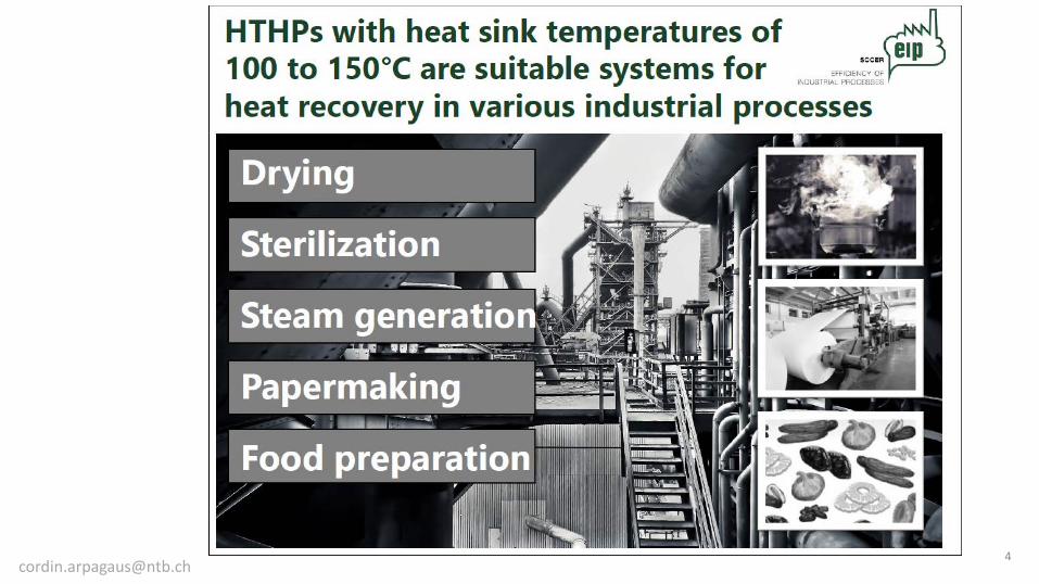
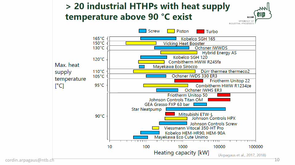
Conclusions • More than 20 industrial HTHPs identified on the market with heat supply
temperatures > 90°C. A few HTHPs exceed 120°C (using R245fa or R365mfc) • COPs range between 1.6 and 5.8 with a temperature lift of 130 to 25 K (40
to 60% 2nd Law efficiency) • Application potentials in industrial waste heat recovery (e.g. drying &
sterilization processes, papermaking, food preparation) • Several R&D projects on an international level (COPs in the range of 5.7 to
6.5 at 30 K temperature lift, 2.2 to 2.8 at 70 K, max. 160°C) • Research trend towards testing
– natural refrigerants (e.g. R718, R744), – hydrocarbons (e.g. R600, R601) – and synthetic HFOs (e.g. R1336mzz(Z), R1234ze(Z), R1233zd(E), and R1224yd(Z))
with low GWP (< 10) [email protected] 26
43
NCC Ost
NürnbergMesse, Arbeitstitel, Datum
Chillventa CONGRESS 2018
Industrial Heat pumps in District Heating Denmark Lars Reinholdt
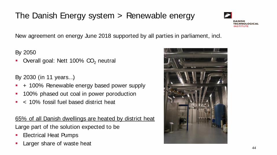
The Danish Energy system > Renewable energy
New agreement on energy June 2018 supported by all parties in parliament, incl. By 2050 Overall goal: Nett 100% CO2 neutral By 2030 (in 11 years…) + 100% Renewable energy based power supply 100% phased out coal in power poroduction < 10% fossil fuel based district heat
65% of all Danish dwellings are heated by district heat Large part of the solution expected to be Electrical Heat Pumps Larger share of waste heat
44
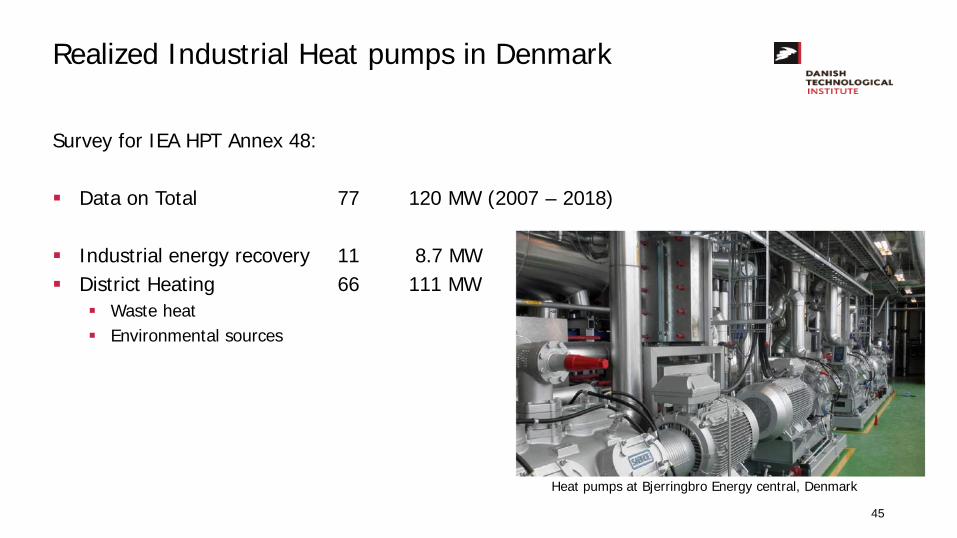
Realized Industrial Heat pumps in Denmark
Survey for IEA HPT Annex 48:
Data on Total 77 120 MW (2007 – 2018)
Industrial energy recovery 11 8.7 MW District Heating 66 111 MW
Waste heat Environmental sources
Heat pumps at Bjerringbro Energy central, Denmark
45
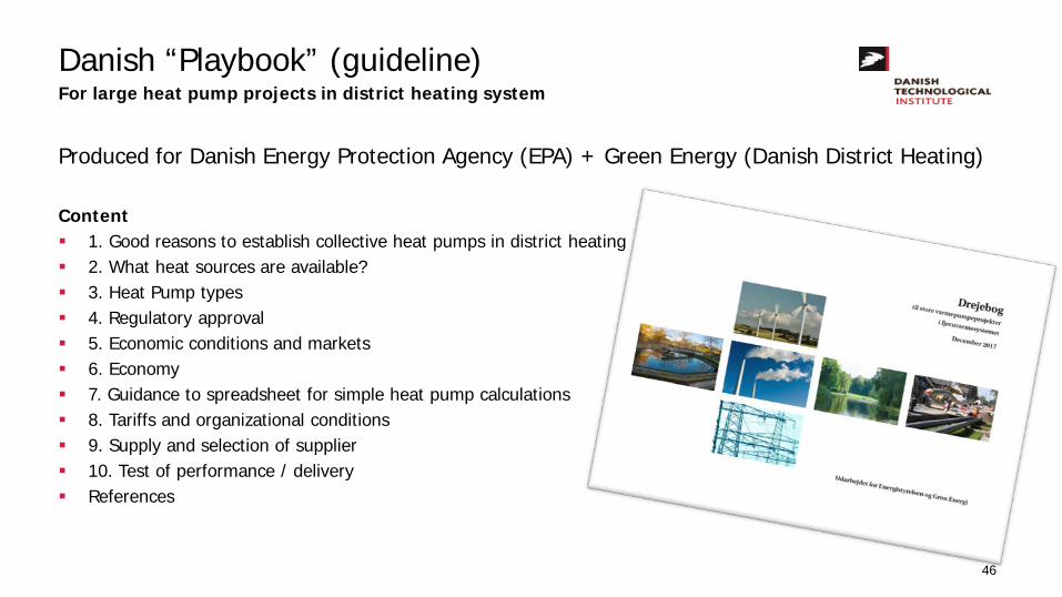
Danish “Playbook” (guideline) For large heat pump projects in district heating system
Produced for Danish Energy Protection Agency (EPA) + Green Energy (Danish District Heating)
Content 1. Good reasons to establish collective heat pumps in district heating 2. What heat sources are available? 3. Heat Pump types 4. Regulatory approval 5. Economic conditions and markets 6. Economy 7. Guidance to spreadsheet for simple heat pump calculations 8. Tariffs and organizational conditions 9. Supply and selection of supplier 10. Test of performance / delivery References
46
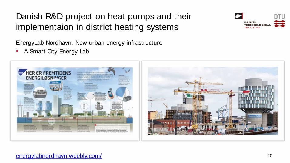
Danish R&D project on heat pumps and their implementaion in district heating systems EnergyLab Nordhavn: New urban energy infrastructure A Smart City Energy Lab
energylabnordhavn.weebly.com/ 47
Conclusion
The Danish energy system is transforming from fossil fuel to electrical power: Electrical heat pumps expected to have a major role in the district heating
The transition process is supported by Guide lines incl. cases Simple calculation tools to make the first estimations
Total cost analysis shows little economic of scale impact high share of other cost than the heat pump it self
Right implementation has to be chosen System COP (COSP) can be much lower than COP of the heat pump
Some relevant Danish R&D project in the field of heat pumps and their implementation was presented
48

2016
0405
/HN
R: V
1.0
Industrial Heat Pump System
Chillventa Congress 15th October 2018
Heat Pumping Technologies for Commercial and
Industrial Applications
50
© 2018 - Viking Heat Engines Germany GmbH – Andre Bechem – Chillventa Congress 15th October 2018
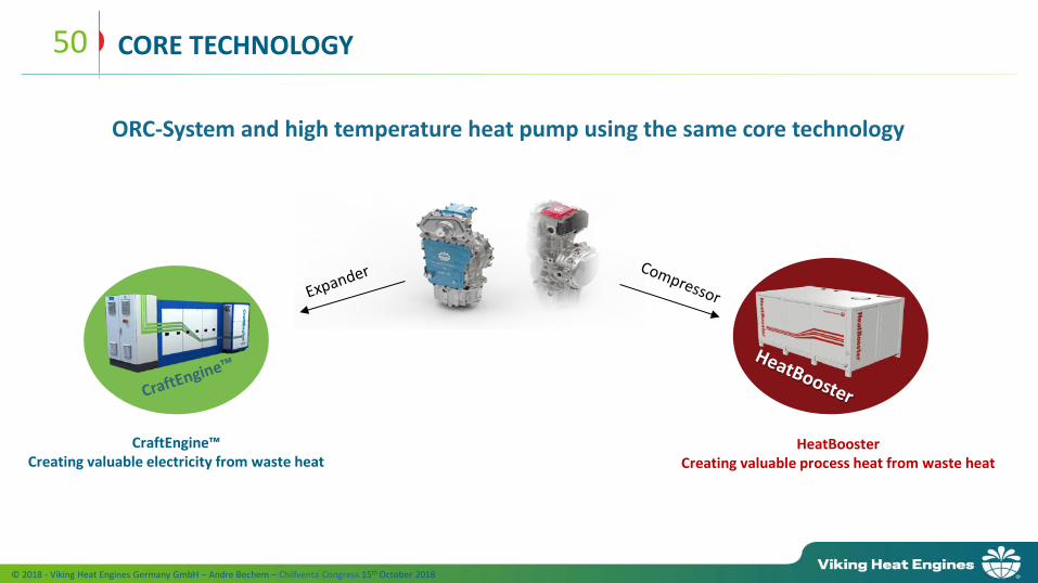
CORE TECHNOLOGY
CraftEngine™ Creating valuable electricity from waste heat
HeatBooster Creating valuable process heat from waste heat
ORC-System and high temperature heat pump using the same core technology
51
© 2018 - Viking Heat Engines Germany GmbH – Andre Bechem – Chillventa Congress 15th October 2018
THE TESTBED IN REMSCHEID FOR ORC-SYSTEMS AND HEAT PUMPS
• Designed and built to automotive standards
• 6 independent test beds
• Heat source up to 250°C and 1 MW thermal
• Heat sink up to 1,2 MW thermal
• AVL Puma control and automation system,
allows 24/7 operation with up to 1000
measurement channels
• High speed pressure measurement incl. in-
cylinder pressure
• Possible to measure key parameters such as:
pressure, temperature, flow rate, viscosity,
vibrations, etc.
52
© 2018 - Viking Heat Engines Germany GmbH – Andre Bechem – Chillventa Congress 15th October 2018
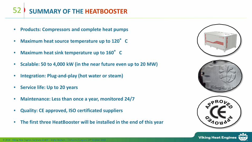
SUMMARY OF THE HEATBOOSTER
• Products: Compressors and complete heat pumps
• Maximum heat source temperature up to 120°C
• Maximum heat sink temperature up to 160°C
• Scalable: 50 to 4,000 kW (in the near future even up to 20 MW)
• Integration: Plug-and-play (hot water or steam)
• Service life: Up to 20 years
• Maintenance: Less than once a year, monitored 24/7
• Quality: CE approved, ISO certificated suppliers
• The first three HeatBooster will be installed in the end of this year
NürnbergMesse, Annex 48 - Task 3, 15.10.2018 Dr. Anna S. Wallerand, [email protected]; [email protected] 53
IEA Industrial Heat Pump Annex 48 – Task 3
“Application of existing models”
NürnbergMesse, Annex 48 - Task 3, 15.10.2018 Dr. Anna S. Wallerand, [email protected]; [email protected]
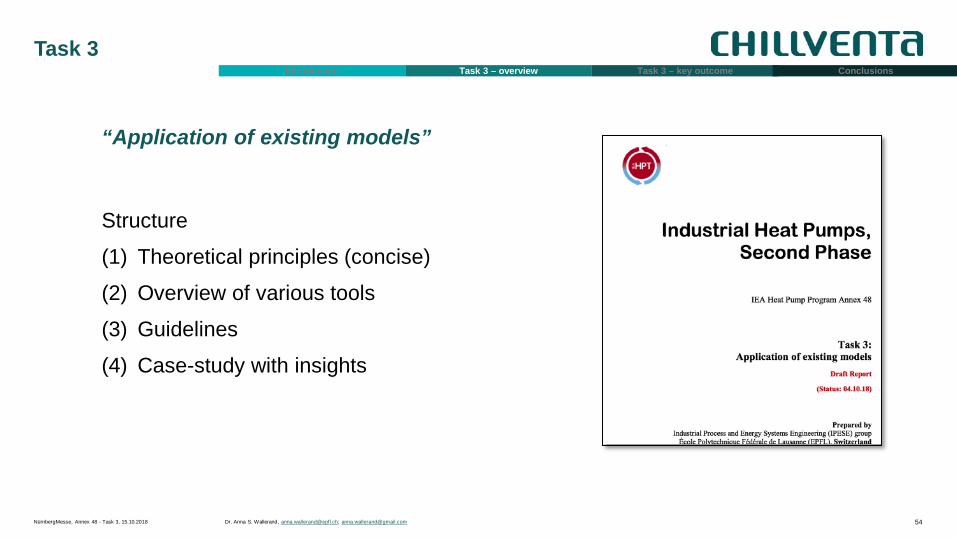
Task 3
54
Introduction Task 3 – overview Task 3 – key outcome Conclusions
“Application of existing models”
Structure
(1) Theoretical principles (concise)
(2) Overview of various tools
(3) Guidelines
(4) Case-study with insights
NürnbergMesse, Annex 48 - Task 3, 15.10.2018 Dr. Anna S. Wallerand, [email protected]; [email protected]
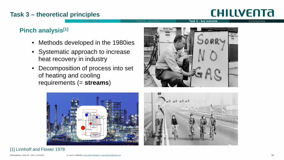
Task 3 – theoretical principles
55
Introduction Task 3 – overview Task 3 – key outcome Conclusions
Pinch analysis[1]
• Methods developed in the 1980ies • Systematic approach to increase
heat recovery in industry • Decomposition of process into set
of heating and cooling requirements (= streams)
[1] Linnhoff and Flower 1978
NürnbergMesse, Annex 48 - Task 3, 15.10.2018 Dr. Anna S. Wallerand, [email protected]; [email protected]
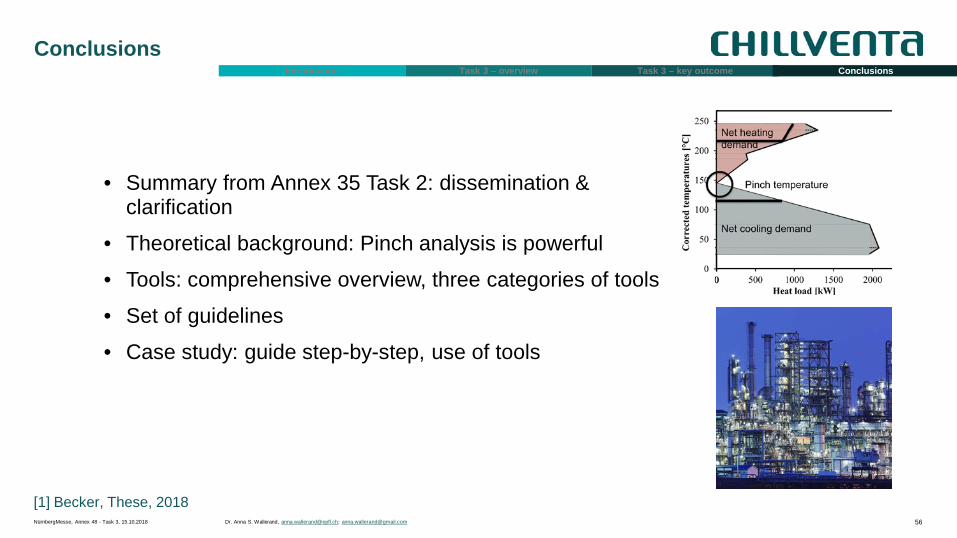
Conclusions
56
Introduction Task 3 – overview Task 3 – key outcome Conclusions
[1] Becker, These, 2018
• Summary from Annex 35 Task 2: dissemination & clarification
• Theoretical background: Pinch analysis is powerful
• Tools: comprehensive overview, three categories of tools
• Set of guidelines
• Case study: guide step-by-step, use of tools

NürnbergMesse, Annex 48 - Task 3, 15.10.2018 Dr. Anna S. Wallerand, [email protected]; [email protected] 57
NCC Ost
Chillventa CONGRESS 2018