Embed Size (px)
Citation preview
Chiral states of electromagnetic fields originated from ferrite-basedmicrowave vortices
M. Sigalov, E. O. Kamenetskii,a� and R. ShavitBen-Gurion University of the Negev, Beer Sheva 84105, Israel
�Received 28 February 2008; accepted 27 October 2008; published online 12 December 2008�
Electromagnetic vortices in a microwave cavity with an inserted piece of a magnetized ferrite appeardue to the time-reversal symmetry breaking effect. We reveal numerically that the Poynting-vectorvortices are possible in open resonant microwave structures with ferrite inclusions. We demonstratea pair of resonances which have opposite vortex rotations at the same direction of time given by thedirection of the magnetization precession. There are two coalescent resonances with differentchirality. We show that the structures of the radiating near and far fields are intimately related to theferrite-induced topological singularities. The observed far-field polarization structures represent adoublet of chiral vortices in space originated from a doublet of resonant chiral states in a patchresonator with an enclosed ferrite disk. © 2008 American Institute of Physics.�DOI: 10.1063/1.3040008�
I. INTRODUCTION
Vortices can be easily observed in water. They are acommon occurrence in plasma science. In recent years, therehas been a considerable interest in vortices of electromag-netic fields. There are electromagnetic processes with brokensymmetry characterized by different topological effects.Study of vortices with optical phase singularities has openedup a new frontier in optics.1 In microwaves, there is a specialinterest in electromagnetic vortices created by ferrite par-ticles with the ferromagnetic resonance �FMR� conditions.
A ferrite is a magnetic dielectric with low losses. Thismay allow for electromagnetic waves to penetrate the ferriteand results in an effective interaction between the electro-magnetic waves and the magnetization within the ferrite.Such an interaction can demonstrate very interesting physicalfeatures. Due to the nonzero purely imaginary off-diagonalcomponent of the permeability tensor in the proximity of theFMR, the phase of the wave reflected from the ferrite-dielectric interface depends on the direction of the incidentwave.2 This time-reversal symmetry �TRS� breaking effect isthe cause why in a resonant structure with an enclosed ferritesample the electromagnetic-field eigenfunctions are com-plex, even in the absence of dissipative losses. This meansthat fields of eigenoscillations are not the fields of standingwaves in spite of the fact that eigenfrequencies of a cavitywith a ferrite sample are real.3 An insertion of a piece of amagnetized ferrite into the resonator domain causes a micro-wave resonator to behave under odd TRS. In this case aferrite sample may act as a topological defect causing in-duced electromagnetic vortices. Based on numerical simula-tion described in Ref. 4 it has been shown that the power-flow lines of the microwave-cavity field interacting with theferrite sample in the proximity of its FMR form whirlpool-like electromagnetic vortices. We found that in such nonin-tegrable structures, magnetic gyrotropy and geometrical fac-
tors lead to the effect of symmetry breaking resulting ineffective chiral magnetic currents and topological magneticcharges.5,6
One of the main features of microwave vortices shownin Refs. 4–6 is the fact that such “swirling entities” appearonly when a ferrite sample is placed in a resonant system.While our previous numerical experiments with ferrite-basedvortices were aimed to analyze the microwave fields inclosed resonant systems �cavities� with low losses, studies offerrite-based vortices in open microwave resonators couldalso be a very attractive problem. In this paper we find that insuch resonant structures one can observe pairs of coalescentresonance modes. Recent experiments7 demonstrate the ef-fects of lifting the degeneracy of resonances in a microwaveresonator with an enclosed ferrite sample. On the other hand,the two-energy-level resonant system exhibiting differentchiralities is known from experimental studies of a dissipa-tive microwave resonator with a special topologicalstructure.8 In the present numerical studies we show that theobserved pairs of resonances in open resonant systems withferrite samples have different directions of the Poynting-vector vortex rotation at the same direction of time. Thereare, in fact, the coalescent resonant states with differentchirality.
Open resonators are radiating systems. A special interestin our problem concerns possible correlation of the electro-magnetic vortex phase singularities and chiral states with thenear-field and far-field properties of the electromagneticfields radiating from open resonant structures with enclosedferrites. Regarding this aspect, it is relevant to note an inter-esting phenomenon of relationships between the vortex-typephase singularities and the far-field radiation pattern whichhas been shown recently in a slit-metal-plate structure.9 Onthe other hand, in Ref. 10 the authors observed handedness-sensitive rotations of the far-field polarization states for vis-ible light diffracted from an artificial planar-chirality me-dium. These experimental results unambiguously show thatpolarization changes in light diffracted from a chiral struc-a�Electronic mail: [email protected].
JOURNAL OF APPLIED PHYSICS 104, 113921 �2008�
0021-8979/2008/104�11�/113921/12/$23.00 © 2008 American Institute of Physics104, 113921-1
Author complimentary copy. Redistribution subject to AIP license or copyright, see http://jap.aip.org/jap/copyright.jsp
ture demonstrate a true signature of the medium chirality.Theoretical studies of this effect are represented in Ref. 11.
Here we show that the Poynting-vector phase singulari-ties and the electromagnetic chiral states of the microwaveresonator with ferrite-based vortices are intimately connectedwith the near-field structure and the far-field pattern of theelectromagnetic fields. For present investigations, we use aradiating patch resonator with an enclosed small ferrite disk.Since the nonintegrable nature of the problem precludes ex-act analytical results for the eigenvalues and eigenfunctions,numerical approaches are required. The analysis is madewith use of the HFSS �the software based on FEM methodproduced by ANSOFT Co.� Computer-aided design simula-tion programs for three-dimensional numerical modeling ofMaxwell equations. In our numerical experiments, both themodulus and the phase of the fields are determined.
II. MAGNETIC GYROTROPY AND CHIRALITY
The effects of chirality shown in this paper are inti-mately connected with magnetic gyrotropy properties of aferrite. The question of magnetic gyrotropy and chirality ap-pears as a fundamental problem in electromagnetism con-cerning relationships between the TRS breaking and paritynonconservation properties. Our studies should be startedwith a brief analysis of this important question.
The electron spins within a magnetized ferrite precesswith their Larmor frequency about the static magnetic fieldand magnetic gyrotropy is observed due to the magnetizationprecession dynamics. This is the TRS breaking phenomenonwhich is described by the Landau-Lifshitz equation �m�
�t =
−�m� �H� , where m� is the magnetization, H� is the magneticfield, and � is the gyromagnetic ratio. In the continual rep-resentation, one has eigenoscillations of magnetization for asaturated ferrite. This eigenprocess is characterized by theright-hand direction of the magnetization precession. For asaturated ferrite, the rf magnetization is caused only by trans-versal �with respect to a direction of a bias dc magnetic field�components of the rf magnetic field. The magnetic suscepti-bility tensor �J becomes nonsymmetrical with antisymmetricoff-diagonal components i�a and −i�a. This property of aferromagnetic medium is called magnetic gyrotropy. In ma-terials with magnetic gyrotropy, one has a local constitutive
relation: B� =�J ·H� , where �J�1+4��J �Ref. 3�. The perme-ability tensor is transposed if the dc magnetic field is re-versed. This can be regarded as the TRS breaking phenom-enon. Due to magnetic gyrotropy, for plane electromagneticwaves propagating in a ferrite medium one has such effectsas the Faraday rotation and birefringence. In microwaves, aferrite is usually described by the scalar electric susceptibil-ity. So no electric gyrotropy is assumed in such a phenom-enon characterization.
Another possibility to obtain the electromagnetic fieldrotation is due to the so-called effects of chirality. In naturalcrystals, chirality �or optical activity� takes place because ofspatial dispersion.12,13 The signs of the antisymmetric com-ponents of the electric susceptibility are reversed when awave vector of a propagating wave changes from k� to −k�.Recently, some artificial chiral materials with nonlocal struc-
tural elements have been suggested for microwave14 andoptical10,11 applications. In fact, there are composites withnonlocal structural elements.15,16 The electromagnetic prop-erties of chiral materials are different from materials withmagnetic gyrotropy. For a plane wave propagating in a ho-mogeneous chiral medium, one has a constitutive
relation:12,13 D� =�E� + iG� �E� , where G� is the gyration vectorwhich is parallel to the wave vector k�. The gyration vector isa time-even pseudoscalar observable. One can rewrite the
constitutive relation for a chiral medium as D� =�JeffE� , where
�Jeff��+ iGJ is the effective permeability tensor and GJ is anantisymmetrical tensor. It is evident that for components ofthe tensor �Jeff in a lossless medium one has ��eff�ij�k��= ��eff� ji
� �−k��.The hallmark of chirality is that it is exhibited by sys-
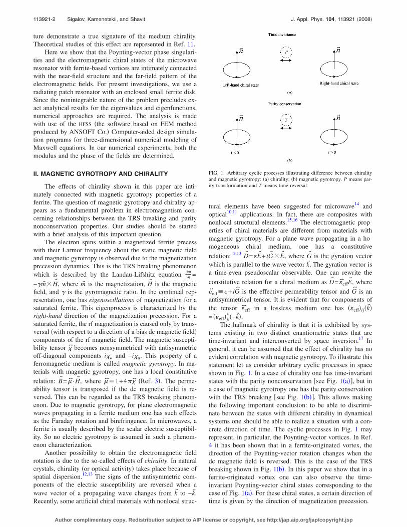
tems existing in two distinct enantiometric states that aretime-invariant and interconverted by space inversion.17 Ingeneral, it can be assumed that the effect of chirality has noevident correlation with magnetic gyrotropy. To illustrate thisstatement let us consider arbitrary cyclic processes in spaceshown in Fig. 1. In a case of chirality one has time-invariantstates with the parity nonconservation �see Fig. 1�a��, but ina case of magnetic gyrotropy one has the parity conservationwith the TRS breaking �see Fig. 1�b��. This allows makingthe following important conclusion: to be able to discrimi-nate between the states with different chirality in dynamicalsystems one should be able to realize a situation with a con-crete direction of time. The cyclic processes in Fig. 1 mayrepresent, in particular, the Poynting-vector vortices. In Ref.4 it has been shown that in a ferrite-originated vortex, thedirection of the Poynting-vector rotation changes when thedc magnetic field is reversed. This is the case of the TRSbreaking shown in Fig. 1�b�. In this paper we show that in aferrite-originated vortex one can also observe the time-invariant Poynting-vector chiral states corresponding to thecase of Fig. 1�a�. For these chiral states, a certain direction oftime is given by the direction of magnetization precession.
FIG. 1. Arbitrary cyclic processes illustrating difference between chiralityand magnetic gyrotropy: �a� chirality; �b� magnetic gyrotropy. P means par-ity transformation and T means time reversal.
113921-2 Sigalov, Kamenetskii, and Shavit J. Appl. Phys. 104, 113921 �2008�
Author complimentary copy. Redistribution subject to AIP license or copyright, see http://jap.aip.org/jap/copyright.jsp
III. TIME REVERSAL SYMMETRY BREAKING ANDTOPOLOGICAL RESONANT STATES IN RESONATORSWITH FERRITE SAMPLES
If the conjugate states �t� and �−t� are macroscopicallydistinctive, the TRS �T symmetry� is broken. In dynamicalprocesses, there can be implications of the combined time-reversal and spatial symmetries. Combination of the time-reversal and spatial symmetries determines the properties ofreciprocity and transmission of electromagnetic waves.18
A ferrite destroys rotational symmetry. For a microwaveresonator with an enclosed ferrite sample, the fact that theresonant fields are not the fields of standing waves3 may givevery specific topological-phase characteristics. The approachusing a random superposition of plane waves may give agood qualitative picture for such topological effects. A spe-cial character of the Poynting-vector distribution in a reso-nant system with a small ferrite sample appears due to thefrequency dependence of the electromagnetic ray trajectoriesfrom a combination of three parameters: a bias magneticfield, frequency, and geometry. When a ferrite sample isplaced in a certain waveguide structure, the points on theferrite-dielectric interfaces become the symmetry breakingplaces. For the TE �or TM� propagating electromagnetic
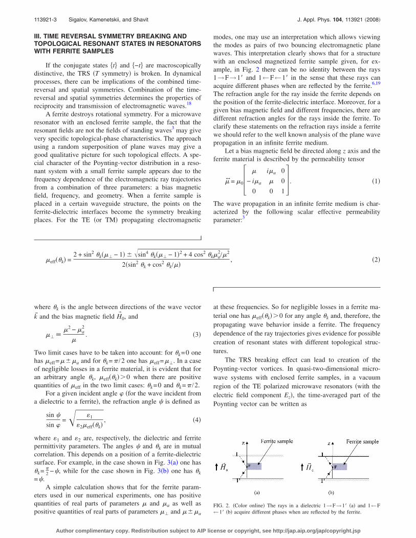
modes, one may use an interpretation which allows viewingthe modes as pairs of two bouncing electromagnetic planewaves. This interpretation clearly shows that for a structurewith an enclosed magnetized ferrite sample given, for ex-ample, in Fig. 2 there can be no identity between the rays1→F→1� and 1←F←1� in the sense that these rays canacquire different phases when are reflected by the ferrite.6,19
The refraction angle for the ray inside the ferrite depends onthe position of the ferrite-dielectric interface. Moreover, for agiven bias magnetic field and different frequencies, there aredifferent refraction angles for the rays inside the ferrite. Toclarify these statements on the refraction rays inside a ferritewe should refer to the well known analysis of the plane wavepropagation in an infinite ferrite medium.
Let a bias magnetic field be directed along z axis and theferrite material is described by the permeability tensor
�J = �0� � i�a 0
− i�a � 0
0 0 1 . �1�
The wave propagation in an infinite ferrite medium is char-acterized by the following scalar effective permeabilityparameter:3
�eff��k� =2 + sin2 �k��� − 1� � sin4 �k��� − 1�2 + 4 cos2 �k�a
2/�2
2�sin2 �k + cos2 �k/��, �2�
where �k is the angle between directions of the wave vector
k� and the bias magnetic field H� 0, and
�� ��2 − �a
2
�. �3�
Two limit cases have to be taken into account: for �k=0 onehas �eff=���a and for �k=� /2 one has �eff=��. In a caseof negligible losses in a ferrite material, it is evident that foran arbitrary angle �k, �eff��k�0 when there are positivequantities of �eff in the two limit cases: �k=0 and �k=� /2.
For a given incident angle �for the wave incident froma dielectric to a ferrite�, the refraction angle � is defined as
sin �
sin = �1
�2�eff��k�, �4�
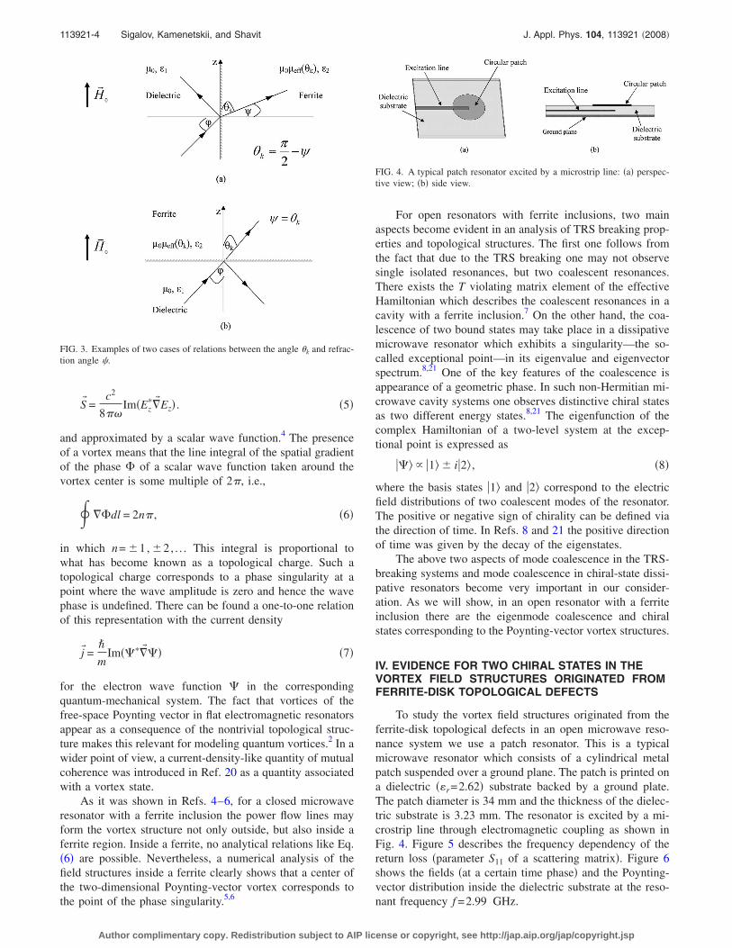
where �1 and �2 are, respectively, the dielectric and ferritepermittivity parameters. The angles � and �k are in mutualcorrelation. This depends on a position of a ferrite-dielectricsurface. For example, in the case shown in Fig. 3�a� one has�k= �
2 −�, while for the case shown in Fig. 3�b� one has �k
=�.A simple calculation shows that for the ferrite param-
eters used in our numerical experiments, one has positivequantities of real parts of parameters � and �a as well aspositive quantities of real parts of parameters �� and ���a
at these frequencies. So for negligible losses in a ferrite ma-terial one has �eff��k�0 for any angle �k and, therefore, thepropagating wave behavior inside a ferrite. The frequencydependence of the ray trajectories gives evidence for possiblecreation of resonant states with different topological struc-tures.
The TRS breaking effect can lead to creation of thePoynting-vector vortices. In quasi-two-dimensional micro-wave systems with enclosed ferrite samples, in a vacuumregion of the TE polarized microwave resonators �with theelectric field component Ez�, the time-averaged part of thePoynting vector can be written as
FIG. 2. �Color online� The rays in a dielectric 1→F→1� �a� and 1←F←1� �b� acquire different phases when are reflected by the ferrite.
113921-3 Sigalov, Kamenetskii, and Shavit J. Appl. Phys. 104, 113921 �2008�
Author complimentary copy. Redistribution subject to AIP license or copyright, see http://jap.aip.org/jap/copyright.jsp
S� =c2
8��Im�Ez
��� Ez� . �5�
and approximated by a scalar wave function.4 The presenceof a vortex means that the line integral of the spatial gradientof the phase of a scalar wave function taken around thevortex center is some multiple of 2�, i.e.,
� � dl = 2n� , �6�
in which n= �1, �2, . . . This integral is proportional towhat has become known as a topological charge. Such atopological charge corresponds to a phase singularity at apoint where the wave amplitude is zero and hence the wavephase is undefined. There can be found a one-to-one relationof this representation with the current density
j� =�
mIm����� �� �7�
for the electron wave function � in the correspondingquantum-mechanical system. The fact that vortices of thefree-space Poynting vector in flat electromagnetic resonatorsappear as a consequence of the nontrivial topological struc-ture makes this relevant for modeling quantum vortices.2 In awider point of view, a current-density-like quantity of mutualcoherence was introduced in Ref. 20 as a quantity associatedwith a vortex state.
As it was shown in Refs. 4–6, for a closed microwaveresonator with a ferrite inclusion the power flow lines mayform the vortex structure not only outside, but also inside aferrite region. Inside a ferrite, no analytical relations like Eq.�6� are possible. Nevertheless, a numerical analysis of thefield structures inside a ferrite clearly shows that a center ofthe two-dimensional Poynting-vector vortex corresponds tothe point of the phase singularity.5,6
For open resonators with ferrite inclusions, two mainaspects become evident in an analysis of TRS breaking prop-erties and topological structures. The first one follows fromthe fact that due to the TRS breaking one may not observesingle isolated resonances, but two coalescent resonances.There exists the T violating matrix element of the effectiveHamiltonian which describes the coalescent resonances in acavity with a ferrite inclusion.7 On the other hand, the coa-lescence of two bound states may take place in a dissipativemicrowave resonator which exhibits a singularity—the so-called exceptional point—in its eigenvalue and eigenvectorspectrum.8,21 One of the key features of the coalescence isappearance of a geometric phase. In such non-Hermitian mi-crowave cavity systems one observes distinctive chiral statesas two different energy states.8,21 The eigenfunction of thecomplex Hamiltonian of a two-level system at the excep-tional point is expressed as
�� � �1 � i�2 , �8�
where the basis states �1 and �2 correspond to the electricfield distributions of two coalescent modes of the resonator.The positive or negative sign of chirality can be defined viathe direction of time. In Refs. 8 and 21 the positive directionof time was given by the decay of the eigenstates.
The above two aspects of mode coalescence in the TRS-breaking systems and mode coalescence in chiral-state dissi-pative resonators become very important in our consider-ation. As we will show, in an open resonator with a ferriteinclusion there are the eigenmode coalescence and chiralstates corresponding to the Poynting-vector vortex structures.
IV. EVIDENCE FOR TWO CHIRAL STATES IN THEVORTEX FIELD STRUCTURES ORIGINATED FROMFERRITE-DISK TOPOLOGICAL DEFECTS
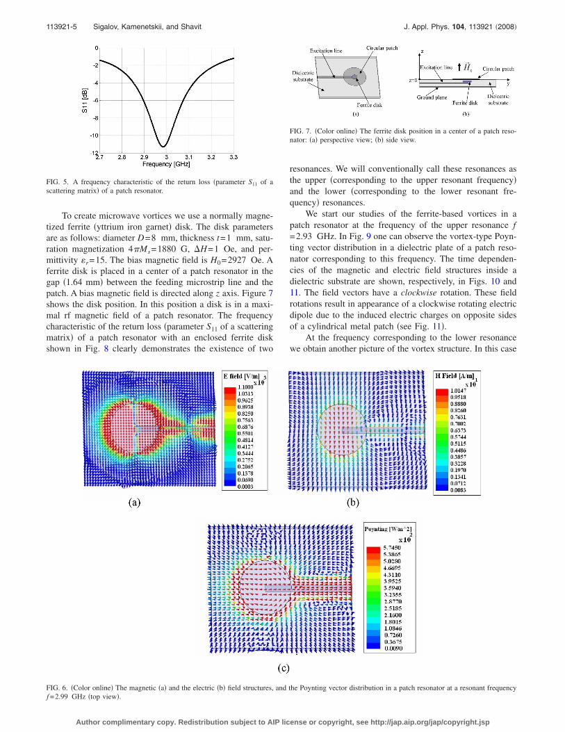
To study the vortex field structures originated from theferrite-disk topological defects in an open microwave reso-nance system we use a patch resonator. This is a typicalmicrowave resonator which consists of a cylindrical metalpatch suspended over a ground plane. The patch is printed ona dielectric ��r=2.62� substrate backed by a ground plate.The patch diameter is 34 mm and the thickness of the dielec-tric substrate is 3.23 mm. The resonator is excited by a mi-crostrip line through electromagnetic coupling as shown inFig. 4. Figure 5 describes the frequency dependency of thereturn loss �parameter S11 of a scattering matrix�. Figure 6shows the fields �at a certain time phase� and the Poynting-vector distribution inside the dielectric substrate at the reso-nant frequency f =2.99 GHz.
FIG. 3. Examples of two cases of relations between the angle �k and refrac-tion angle �.
FIG. 4. A typical patch resonator excited by a microstrip line: �a� perspec-tive view; �b� side view.
113921-4 Sigalov, Kamenetskii, and Shavit J. Appl. Phys. 104, 113921 �2008�
Author complimentary copy. Redistribution subject to AIP license or copyright, see http://jap.aip.org/jap/copyright.jsp
To create microwave vortices we use a normally magne-tized ferrite �yttrium iron garnet� disk. The disk parametersare as follows: diameter D=8 mm, thickness t=1 mm, satu-ration magnetization 4�Ms=1880 G, �H=1 Oe, and per-mittivity �r=15. The bias magnetic field is H0=2927 Oe. Aferrite disk is placed in a center of a patch resonator in thegap �1.64 mm� between the feeding microstrip line and thepatch. A bias magnetic field is directed along z axis. Figure 7shows the disk position. In this position a disk is in a maxi-mal rf magnetic field of a patch resonator. The frequencycharacteristic of the return loss �parameter S11 of a scatteringmatrix� of a patch resonator with an enclosed ferrite diskshown in Fig. 8 clearly demonstrates the existence of two
resonances. We will conventionally call these resonances asthe upper �corresponding to the upper resonant frequency�and the lower �corresponding to the lower resonant fre-quency� resonances.
We start our studies of the ferrite-based vortices in apatch resonator at the frequency of the upper resonance f=2.93 GHz. In Fig. 9 one can observe the vortex-type Poyn-ting vector distribution in a dielectric plate of a patch reso-nator corresponding to this frequency. The time dependen-cies of the magnetic and electric field structures inside adielectric substrate are shown, respectively, in Figs. 10 and11. The field vectors have a clockwise rotation. These fieldrotations result in appearance of a clockwise rotating electricdipole due to the induced electric charges on opposite sidesof a cylindrical metal patch �see Fig. 11�.
At the frequency corresponding to the lower resonancewe obtain another picture of the vortex structure. In this case
FIG. 5. A frequency characteristic of the return loss �parameter S11 of ascattering matrix� of a patch resonator.
FIG. 6. �Color online� The magnetic �a� and the electric �b� field structures, and the Poynting vector distribution in a patch resonator at a resonant frequencyf =2.99 GHz �top view�.
FIG. 7. �Color online� The ferrite disk position in a center of a patch reso-nator: �a� perspective view; �b� side view.
113921-5 Sigalov, Kamenetskii, and Shavit J. Appl. Phys. 104, 113921 �2008�
Author complimentary copy. Redistribution subject to AIP license or copyright, see http://jap.aip.org/jap/copyright.jsp
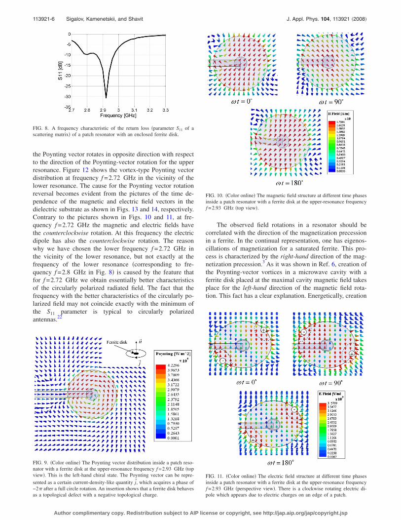
the Poynting vector rotates in opposite direction with respectto the direction of the Poynting-vector rotation for the upperresonance. Figure 12 shows the vortex-type Poynting vectordistribution at frequency f =2.72 GHz in the vicinity of thelower resonance. The cause for the Poynting vector rotationreversal becomes evident from the pictures of the time de-pendence of the magnetic and electric field vectors in thedielectric substrate as shown in Figs. 13 and 14, respectively.Contrary to the pictures shown in Figs. 10 and 11, at fre-quency f =2.72 GHz the magnetic and electric fields havethe counterclockwise rotation. At this frequency the electricdipole has also the counterclockwise rotation. The reasonwhy we have chosen the lower frequency f =2.72 GHz inthe vicinity of the lower resonance, but not exactly at thefrequency of the lower resonance �corresponding to fre-quency f =2.8 GHz in Fig. 8� is caused by the feature thatfor f =2.72 GHz we obtain essentially better characteristicsof the circularly polarized radiated field. The fact that thefrequency with the better characteristics of the circularly po-larized field may not coincide exactly with the minimum ofthe S11 parameter is typical to circularly polarizedantennas.22
The observed field rotations in a resonator should becorrelated with the direction of the magnetization precessionin a ferrite. In the continual representation, one has eigenos-cillations of magnetization for a saturated ferrite. This pro-cess is characterized by the right-hand direction of the mag-netization precession.3 As it was shown in Ref. 6, creation ofthe Poynting-vector vortices in a microwave cavity with aferrite disk placed at the maximal cavity magnetic field takesplace for the left-hand direction of the magnetic field rota-tion. This fact has a clear explanation. Energetically, creation
FIG. 8. A frequency characteristic of the return loss �parameter S11 of ascattering matrix� of a patch resonator with an enclosed ferrite disk.
FIG. 9. �Color online� The Poynting vector distribution inside a patch reso-nator with a ferrite disk at the upper-resonance frequency f =2.93 GHz �topview�. This is the left-hand chiral state. The Poynting vector can be repre-sented as a certain current-density-like quantity j�, which acquires a phase of−2� after a full circle rotation. An insertion shows that a ferrite disk behavesas a topological defect with a negative topological charge.
FIG. 10. �Color online� The magnetic field structure at different time phasesinside a patch resonator with a ferrite disk at the upper-resonance frequencyf =2.93 GHz �top view�.
FIG. 11. �Color online� The electric field structure at different time phasesinside a patch resonator with a ferrite disk at the upper-resonance frequencyf =2.93 GHz �perspective view�. There is a clockwise rotating electric di-pole which appears due to electric charges on an edge of a patch.
113921-6 Sigalov, Kamenetskii, and Shavit J. Appl. Phys. 104, 113921 �2008�
Author complimentary copy. Redistribution subject to AIP license or copyright, see http://jap.aip.org/jap/copyright.jsp
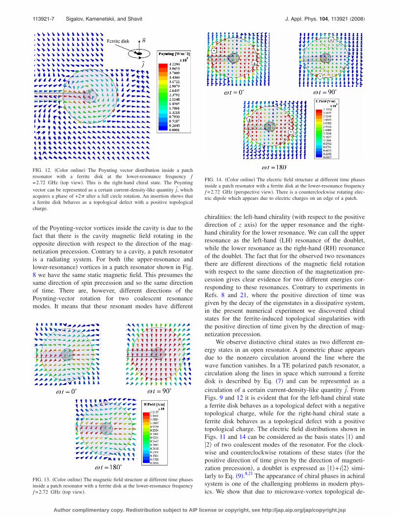
of the Poynting-vector vortices inside the cavity is due to thefact that there is the cavity magnetic field rotating in theopposite direction with respect to the direction of the mag-netization precession. Contrary to a cavity, a patch resonatoris a radiating system. For both �the upper-resonance andlower-resonance� vortices in a patch resonator shown in Fig.8 we have the same static magnetic field. This presumes thesame direction of spin precession and so the same directionof time. There are, however, different directions of thePoynting-vector rotation for two coalescent resonancemodes. It means that these resonant modes have different
chiralities: the left-hand chirality �with respect to the positivedirection of z axis� for the upper resonance and the right-hand chirality for the lower resonance. We can call the upperresonance as the left-hand �LH� resonance of the doublet,while the lower resonance as the right-hand �RH� resonanceof the doublet. The fact that for the observed two resonancesthere are different directions of the magnetic field rotationwith respect to the same direction of the magnetization pre-cession gives clear evidence for two different energies cor-responding to these resonances. Contrary to experiments inRefs. 8 and 21, where the positive direction of time wasgiven by the decay of the eigenstates in a dissipative system,in the present numerical experiment we discovered chiralstates for the ferrite-induced topological singularities withthe positive direction of time given by the direction of mag-netization precession.
We observe distinctive chiral states as two different en-ergy states in an open resonator. A geometric phase appearsdue to the nonzero circulation around the line where thewave function vanishes. In a TE polarized patch resonator, acirculation along the lines in space which surround a ferritedisk is described by Eq. �7� and can be represented as acirculation of a certain current-density-like quantity j�. FromFigs. 9 and 12 it is evident that for the left-hand chiral statea ferrite disk behaves as a topological defect with a negativetopological charge, while for the right-hand chiral state aferrite disk behaves as a topological defect with a positivetopological charge. The electric field distributions shown inFigs. 11 and 14 can be considered as the basis states �1 and�2 of two coalescent modes of the resonator. For the clock-wise and counterclockwise rotations of these states �for thepositive direction of time given by the direction of magneti-zation precession�, a doublet is expressed as �1 + i�2 simi-larly to Eq. �9�.8,21 The appearance of chiral phases in achiralsystem is one of the challenging problems in modern phys-ics. We show that due to microwave-vortex topological de-
FIG. 12. �Color online� The Poynting vector distribution inside a patchresonator with a ferrite disk at the lower-resonance frequency f=2.72 GHz �top view�. This is the right-hand chiral state. The Poyntingvector can be represented as a certain current-density-like quantity j�, whichacquires a phase of +2� after a full circle rotation. An insertion shows thata ferrite disk behaves as a topological defect with a positive topologicalcharge.
FIG. 13. �Color online� The magnetic field structure at different time phasesinside a patch resonator with a ferrite disk at the lower-resonance frequencyf =2.72 GHz �top view�.
FIG. 14. �Color online� The electric field structure at different time phasesinside a patch resonator with a ferrite disk at the lower-resonance frequencyf =2.72 GHz �perspective view�. There is a counterclockwise rotating elec-tric dipole which appears due to electric charges on an edge of a patch.
113921-7 Sigalov, Kamenetskii, and Shavit J. Appl. Phys. 104, 113921 �2008�
Author complimentary copy. Redistribution subject to AIP license or copyright, see http://jap.aip.org/jap/copyright.jsp
fects originated by small ferrite particles, magnetic gyrotropycan stipulate chirality in achiral electromagnetic structures.For the time invariance �because of a given direction of abias magnetic field�, one has clear discrimination of the chi-ral states �see Fig. 1�a��.
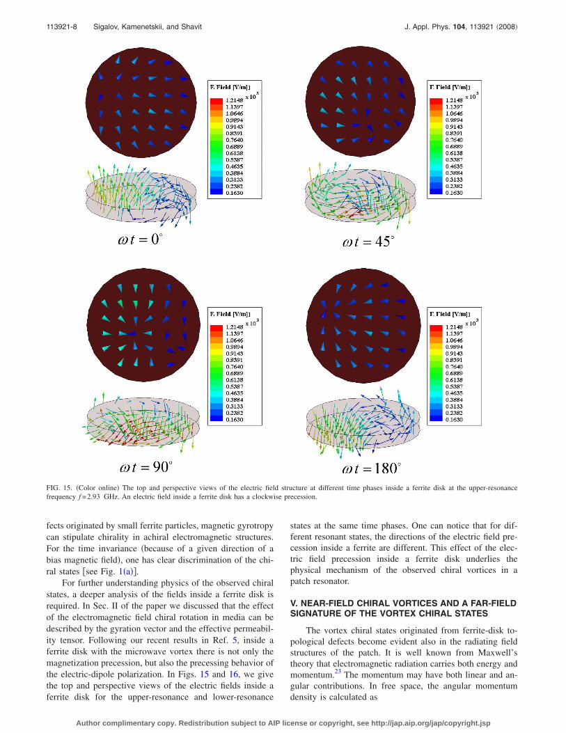
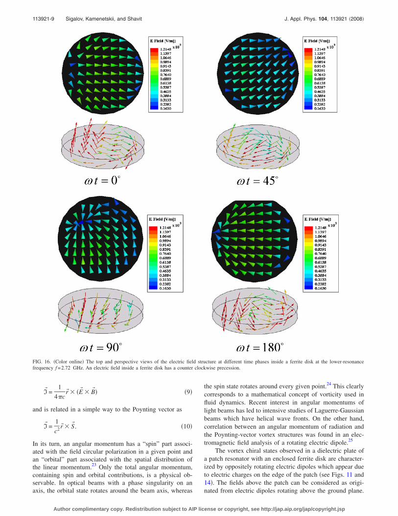
For further understanding physics of the observed chiralstates, a deeper analysis of the fields inside a ferrite disk isrequired. In Sec. II of the paper we discussed that the effectof the electromagnetic field chiral rotation in media can bedescribed by the gyration vector and the effective permeabil-ity tensor. Following our recent results in Ref. 5, inside aferrite disk with the microwave vortex there is not only themagnetization precession, but also the precessing behavior ofthe electric-dipole polarization. In Figs. 15 and 16, we givethe top and perspective views of the electric fields inside aferrite disk for the upper-resonance and lower-resonance
states at the same time phases. One can notice that for dif-ferent resonant states, the directions of the electric field pre-cession inside a ferrite are different. This effect of the elec-tric field precession inside a ferrite disk underlies thephysical mechanism of the observed chiral vortices in apatch resonator.
V. NEAR-FIELD CHIRAL VORTICES AND A FAR-FIELDSIGNATURE OF THE VORTEX CHIRAL STATES
The vortex chiral states originated from ferrite-disk to-pological defects become evident also in the radiating fieldstructures of the patch. It is well known from Maxwell’stheory that electromagnetic radiation carries both energy andmomentum.23 The momentum may have both linear and an-gular contributions. In free space, the angular momentumdensity is calculated as
FIG. 15. �Color online� The top and perspective views of the electric field structure at different time phases inside a ferrite disk at the upper-resonancefrequency f =2.93 GHz. An electric field inside a ferrite disk has a clockwise precession.
113921-8 Sigalov, Kamenetskii, and Shavit J. Appl. Phys. 104, 113921 �2008�
Author complimentary copy. Redistribution subject to AIP license or copyright, see http://jap.aip.org/jap/copyright.jsp
I� =1
4�cr� � �E� � B� � �9�
and is related in a simple way to the Poynting vector as
I� =1
c2r� � S� . �10�
In its turn, an angular momentum has a “spin” part associ-ated with the field circular polarization in a given point andan “orbital” part associated with the spatial distribution ofthe linear momentum.23 Only the total angular momentum,containing spin and orbital contributions, is a physical ob-servable. In optical beams with a phase singularity on anaxis, the orbital state rotates around the beam axis, whereas
the spin state rotates around every given point.24 This clearlycorresponds to a mathematical concept of vorticity used influid dynamics. Recent interest in angular momentums oflight beams has led to intensive studies of Laguerre-Gaussianbeams which have helical wave fronts. On the other hand,correlation between an angular momentum of radiation andthe Poynting-vector vortex structures was found in an elec-tromagnetic field analysis of a rotating electric dipole.25
The vortex chiral states observed in a dielectric plate ofa patch resonator with an enclosed ferrite disk are character-ized by oppositely rotating electric dipoles which appear dueto electric charges on the edge of the patch �see Figs. 11 and14�. The fields above the patch can be considered as origi-nated from electric dipoles rotating above the ground plane.
FIG. 16. �Color online� The top and perspective views of the electric field structure at different time phases inside a ferrite disk at the lower-resonancefrequency f =2.72 GHz. An electric field inside a ferrite disk has a counter clockwise precession.
113921-9 Sigalov, Kamenetskii, and Shavit J. Appl. Phys. 104, 113921 �2008�
Author complimentary copy. Redistribution subject to AIP license or copyright, see http://jap.aip.org/jap/copyright.jsp
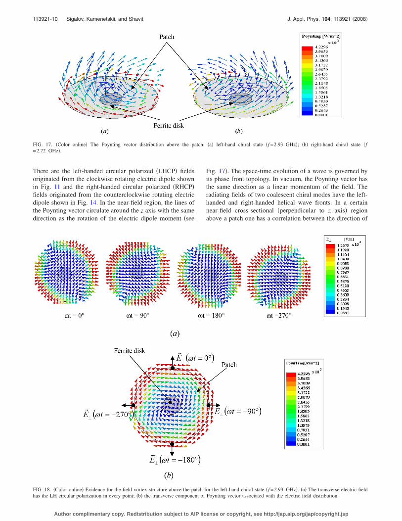
There are the left-handed circular polarized �LHCP� fieldsoriginated from the clockwise rotating electric dipole shownin Fig. 11 and the right-handed circular polarized �RHCP�fields originated from the counterclockwise rotating electricdipole shown in Fig. 14. In the near-field region, the lines ofthe Poynting vector circulate around the z axis with the samedirection as the rotation of the electric dipole moment �see
Fig. 17�. The space-time evolution of a wave is governed byits phase front topology. In vacuum, the Poynting vector hasthe same direction as a linear momentum of the field. Theradiating fields of two coalescent chiral modes have the left-handed and right-handed helical wave fronts. In a certainnear-field cross-sectional �perpendicular to z axis� regionabove a patch one has a correlation between the direction of
FIG. 18. �Color online� Evidence for the field vortex structure above the patch for the left-hand chiral state �f =2.93 GHz�. �a� The transverse electric fieldhas the LH circular polarization in every point; �b� the transverse component of Poynting vector associated with the electric field distribution.
FIG. 17. �Color online� The Poynting vector distribution above the patch: �a� left-hand chiral state �f =2.93 GHz�; �b� right-hand chiral state �f=2.72 GHz�.
113921-10 Sigalov, Kamenetskii, and Shavit J. Appl. Phys. 104, 113921 �2008�
Author complimentary copy. Redistribution subject to AIP license or copyright, see http://jap.aip.org/jap/copyright.jsp
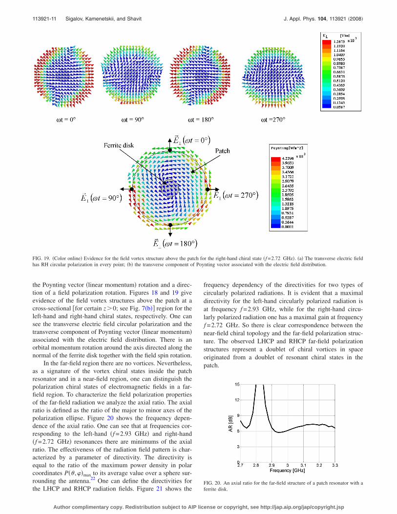
the Poynting vector �linear momentum� rotation and a direc-tion of a field polarization rotation. Figures 18 and 19 giveevidence of the field vortex structures above the patch at across-sectional �for certain z0; see Fig. 7�b�� region for theleft-hand and right-hand chiral states, respectively. One cansee the transverse electric field circular polarization and thetransverse component of Poynting vector �linear momentum�associated with the electric field distribution. There is anorbital momentum rotation around the axis directed along thenormal of the ferrite disk together with the field spin rotation.
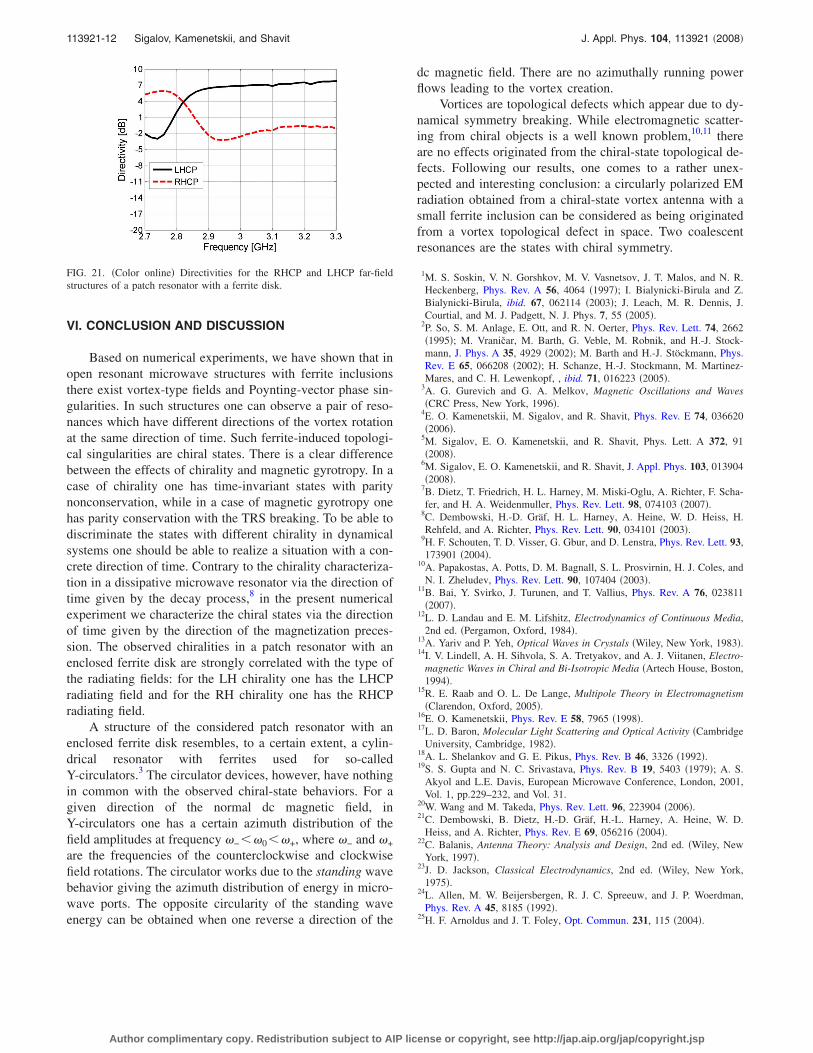
In the far-field region there are no vortices. Nevertheless,as a signature of the vortex chiral states inside the patchresonator and in a near-field region, one can distinguish thepolarization chiral states of electromagnetic fields in a far-field region. To characterize the field polarization propertiesof the far-field radiation we analyze the axial ratio. The axialratio is defined as the ratio of the major to minor axes of thepolarization ellipse. Figure 20 shows the frequency depen-dence of the axial ratio. One can see that at frequencies cor-responding to the left-hand �f =2.93 GHz� and right-hand�f =2.72 GHz� resonances there are minimums of the axialratio. The effectiveness of the radiation field pattern is char-acterized by a parameter of directivity. The directivity isequal to the ratio of the maximum power density in polarcoordinates P�� ,�max to its average value over a sphere sur-rounding the antenna.22 One can define the directivities forthe LHCP and RHCP radiation fields. Figure 21 shows the
frequency dependency of the directivities for two types ofcircularly polarized radiations. It is evident that a maximaldirectivity for the left-hand circularly polarized radiation isat frequency f =2.93 GHz, while for the right-hand circu-larly polarized radiation one has a maximal gain at frequencyf =2.72 GHz. So there is clear correspondence between thenear-field chiral topology and the far-field polarization struc-ture. The observed LHCP and RHCP far-field polarizationstructures represent a doublet of chiral vortices in spaceoriginated from a doublet of resonant chiral states in thepatch.
FIG. 19. �Color online� Evidence for the field vortex structure above the patch for the right-hand chiral state �f =2.72 GHz�. �a� The transverse electric fieldhas RH circular polarization in every point; �b� the transverse component of Poynting vector associated with the electric field distribution.
FIG. 20. An axial ratio for the far-field structure of a patch resonator with aferrite disk.
113921-11 Sigalov, Kamenetskii, and Shavit J. Appl. Phys. 104, 113921 �2008�
Author complimentary copy. Redistribution subject to AIP license or copyright, see http://jap.aip.org/jap/copyright.jsp
VI. CONCLUSION AND DISCUSSION
Based on numerical experiments, we have shown that inopen resonant microwave structures with ferrite inclusionsthere exist vortex-type fields and Poynting-vector phase sin-gularities. In such structures one can observe a pair of reso-nances which have different directions of the vortex rotationat the same direction of time. Such ferrite-induced topologi-cal singularities are chiral states. There is a clear differencebetween the effects of chirality and magnetic gyrotropy. In acase of chirality one has time-invariant states with paritynonconservation, while in a case of magnetic gyrotropy onehas parity conservation with the TRS breaking. To be able todiscriminate the states with different chirality in dynamicalsystems one should be able to realize a situation with a con-crete direction of time. Contrary to the chirality characteriza-tion in a dissipative microwave resonator via the direction oftime given by the decay process,8 in the present numericalexperiment we characterize the chiral states via the directionof time given by the direction of the magnetization preces-sion. The observed chiralities in a patch resonator with anenclosed ferrite disk are strongly correlated with the type ofthe radiating fields: for the LH chirality one has the LHCPradiating field and for the RH chirality one has the RHCPradiating field.
A structure of the considered patch resonator with anenclosed ferrite disk resembles, to a certain extent, a cylin-drical resonator with ferrites used for so-calledY-circulators.3 The circulator devices, however, have nothingin common with the observed chiral-state behaviors. For agiven direction of the normal dc magnetic field, inY-circulators one has a certain azimuth distribution of thefield amplitudes at frequency �−��0��+, where �− and �+
are the frequencies of the counterclockwise and clockwisefield rotations. The circulator works due to the standing wavebehavior giving the azimuth distribution of energy in micro-wave ports. The opposite circularity of the standing waveenergy can be obtained when one reverse a direction of the
dc magnetic field. There are no azimuthally running powerflows leading to the vortex creation.
Vortices are topological defects which appear due to dy-namical symmetry breaking. While electromagnetic scatter-ing from chiral objects is a well known problem,10,11 thereare no effects originated from the chiral-state topological de-fects. Following our results, one comes to a rather unex-pected and interesting conclusion: a circularly polarized EMradiation obtained from a chiral-state vortex antenna with asmall ferrite inclusion can be considered as being originatedfrom a vortex topological defect in space. Two coalescentresonances are the states with chiral symmetry.
1M. S. Soskin, V. N. Gorshkov, M. V. Vasnetsov, J. T. Malos, and N. R.Heckenberg, Phys. Rev. A 56, 4064 �1997�; I. Bialynicki-Birula and Z.Bialynicki-Birula, ibid. 67, 062114 �2003�; J. Leach, M. R. Dennis, J.Courtial, and M. J. Padgett, N. J. Phys. 7, 55 �2005�.
2P. So, S. M. Anlage, E. Ott, and R. N. Oerter, Phys. Rev. Lett. 74, 2662�1995�; M. Vraničar, M. Barth, G. Veble, M. Robnik, and H.-J. Stock-mann, J. Phys. A 35, 4929 �2002�; M. Barth and H.-J. Stöckmann, Phys.Rev. E 65, 066208 �2002�; H. Schanze, H.-J. Stockmann, M. Martinez-Mares, and C. H. Lewenkopf, , ibid. 71, 016223 �2005�.
3A. G. Gurevich and G. A. Melkov, Magnetic Oscillations and Waves�CRC Press, New York, 1996�.
4E. O. Kamenetskii, M. Sigalov, and R. Shavit, Phys. Rev. E 74, 036620�2006�.
5M. Sigalov, E. O. Kamenetskii, and R. Shavit, Phys. Lett. A 372, 91�2008�.
6M. Sigalov, E. O. Kamenetskii, and R. Shavit, J. Appl. Phys. 103, 013904�2008�.
7B. Dietz, T. Friedrich, H. L. Harney, M. Miski-Oglu, A. Richter, F. Scha-fer, and H. A. Weidenmuller, Phys. Rev. Lett. 98, 074103 �2007�.
8C. Dembowski, H.-D. Gräf, H. L. Harney, A. Heine, W. D. Heiss, H.Rehfeld, and A. Richter, Phys. Rev. Lett. 90, 034101 �2003�.
9H. F. Schouten, T. D. Visser, G. Gbur, and D. Lenstra, Phys. Rev. Lett. 93,173901 �2004�.
10A. Papakostas, A. Potts, D. M. Bagnall, S. L. Prosvirnin, H. J. Coles, andN. I. Zheludev, Phys. Rev. Lett. 90, 107404 �2003�.
11B. Bai, Y. Svirko, J. Turunen, and T. Vallius, Phys. Rev. A 76, 023811�2007�.
12L. D. Landau and E. M. Lifshitz, Electrodynamics of Continuous Media,2nd ed. �Pergamon, Oxford, 1984�.
13A. Yariv and P. Yeh, Optical Waves in Crystals �Wiley, New York, 1983�.14I. V. Lindell, A. H. Sihvola, S. A. Tretyakov, and A. J. Viitanen, Electro-
magnetic Waves in Chiral and Bi-Isotropic Media �Artech House, Boston,1994�.
15R. E. Raab and O. L. De Lange, Multipole Theory in Electromagnetism�Clarendon, Oxford, 2005�.
16E. O. Kamenetskii, Phys. Rev. E 58, 7965 �1998�.17L. D. Baron, Molecular Light Scattering and Optical Activity �Cambridge
University, Cambridge, 1982�.18A. L. Shelankov and G. E. Pikus, Phys. Rev. B 46, 3326 �1992�.19S. S. Gupta and N. C. Srivastava, Phys. Rev. B 19, 5403 �1979�; A. S.
Akyol and L.E. Davis, European Microwave Conference, London, 2001,Vol. 1, pp.229–232, and Vol. 31.
20W. Wang and M. Takeda, Phys. Rev. Lett. 96, 223904 �2006�.21C. Dembowski, B. Dietz, H.-D. Gräf, H.-L. Harney, A. Heine, W. D.
Heiss, and A. Richter, Phys. Rev. E 69, 056216 �2004�.22C. Balanis, Antenna Theory: Analysis and Design, 2nd ed. �Wiley, New
York, 1997�.23J. D. Jackson, Classical Electrodynamics, 2nd ed. �Wiley, New York,
1975�.24L. Allen, M. W. Beijersbergen, R. J. C. Spreeuw, and J. P. Woerdman,
Phys. Rev. A 45, 8185 �1992�.25H. F. Arnoldus and J. T. Foley, Opt. Commun. 231, 115 �2004�.
FIG. 21. �Color online� Directivities for the RHCP and LHCP far-fieldstructures of a patch resonator with a ferrite disk.
113921-12 Sigalov, Kamenetskii, and Shavit J. Appl. Phys. 104, 113921 �2008�
Author complimentary copy. Redistribution subject to AIP license or copyright, see http://jap.aip.org/jap/copyright.jsp