Embed Size (px)
Citation preview
Choosing a Machine for Efficient Processing of Cast Polyurethane
Jim Riley
Baulé USA LLC Coraopolis, PA
Presented at the 2013 PMA Las Vegas Nevada
Abstract Many experienced and knowledgeable people in the cast polyurethane industry purchase processing equipment based strictly on price and not processing capability. The user’s present and future processing needs are never properly evaluated and used to purchase the machine which offers the optimum value. This paper will provide parameters to help a molder evaluate their machinery needs. These parameters will then be used to help determine the machine output range, optimum number of chemical components, tank sizing, and number of additive injection units. In addition, machine controls, level controls, agitator selection, and required accessories for degassing and feeding and melting of MBOCA will also be reviewed.
Introduction All companies have financial limitations and cannot overspend on capital equipment if they wish to be successful in business. However, when many companies make plans to purchase polyurethane equipment, they develop their budget and come up with numbers without taking many important factors into account. A new order they received, or a sudden realization of “a lack of capacity” with present equipment, etc., causes the buyer to develop “tunnel vision” and overlook many factors beyond the present situation they should be considering before buying a machine. They often buy a machine at a low price but it ends up not providing the best value in the long run.
Moving from Hand Casting to a Machine The first topic I would like to touch on is the desire to purchase in the first place. People who hand cast their products are sometimes slow to change. As they see it, there are advantages to hand casting in that they have a number of different systems they use in small quantities and can change back and forth between systems quickly. In addition, a hand caster does not need to deal with the capital expenditure required to purchase a machine or the maintenance issues involved with using a machine. This may be correct. However, some of these same people will continue to use the same TDI or MDI systems in 5 or 6 hardnesses and never consider going to
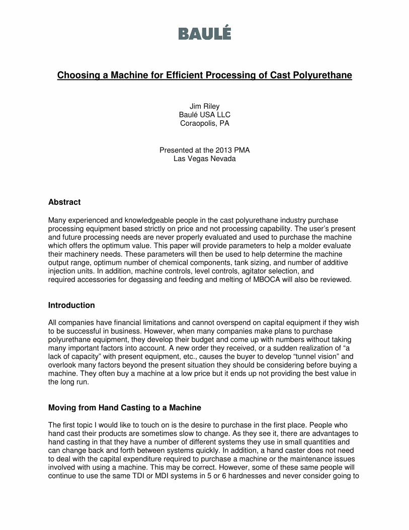
an MDI quasi system or blending two TDI materials, at each end of the hardness scale, to provide a range of hardnesses from 3 materials rather than 6 or 7. When a company that is hand casting moves to a machine they are usually amazed at how quickly the machine can condition the chemicals and mix and dispense them into molds. They soon realize they do not need as much man power to produce the same number of parts and the consistency of the final parts improve. Large parts that were once a major hassle or virtually impossible to hand cast are now done quite easily. They also come to realize their chemical usage, for the same number of parts, is down; chemical waste has decreased. Finally, they come to appreciate the fact that they are spending a lot less time handling the chemicals; chemical exposure has been reduced.
3 Component Casting Machine
In general, when using a machine, you will have better degassing of your materials. You will also have better temperature control, better ratio control, superior mixing of the chemicals and ultimately a better product.
Preparing to Purchase a Machine After you decide to purchase a machine, you will contact machine companies to obtain information and pricing. Before making any decisions you should review all the chemicals that you are presently running and record them along with their characteristics. In addition, you should consider what you might be molding for the next 2-5 years and make an attempt to determine which types of materials these parts may require. Make a list of these parts also. Now that you have a good idea of your current chemicals and a reasonable idea of the chemical systems that you might be considering in the future, you need to determine your product mix. It is extremely important to know if a certain part you make, that requires a specific chemical system, is 90% of your total production or 10%. Make a chart or list of the parts you make noting the volume of each part, the chemical system used for each part, hardness, weight, etc. If you are concerned about conveying this information to a machine vendor, code the parts in some way to avoid identification by non-company personnel. The main point is to share your production mix with the machine vendor so they can use their expertise to make suggestions and spot problem areas. I have seen numerous customers trying to equip a machine to handle all their products including one, which is non-typical, that makes up less than 1% of their product mix. This single part can drive the machine price up by thousands of dollars, because of unusual size or some peculiarity, and comprises machine efficiency for the remaining 99% of their product line. You do not want the majority of your parts to suffer just to satisfy a few.
Oftentimes, removing the low volume, unusual size, or peculiar part from the machine mix will save money, improve the efficiency of your machine, and result in better product quality. Hand cast the low volume “out of range” parts.
Number of Machine Circuits You now know what product mix you have and the various materials you anticipate running. The next item you must look at is the number of component circuits the new machine will have. Many companies will seek the least expensive machine and will immediately assume they need a 2 component machine if they are running 2 component systems. This may be correct. However, by doing so make sure you realize that you will eliminate your ability to run any quasi MDI systems or blend TDI systems for multiple hardness capability. Also, you will not be able to run any standard 3 component systems with the machine. You will also lose the flexibility of running an ether and ester chemical system on the same machine with a common curative. A 2 component machine will work well in certain scenarios but a 3 component machine is much more flexible and may offer better long term value even though the initial purchase price could be 30-50% higher than a like size 2-component machine. In many scenarios a 3 component machine can be as productive as 2 – 2 component machines. If you are running a material that contains more than 3 components, then you will have no choice but to purchase a machine that has the same number of circuits as the chemical systems you are using. Machines are available to handle up to 6 main components.
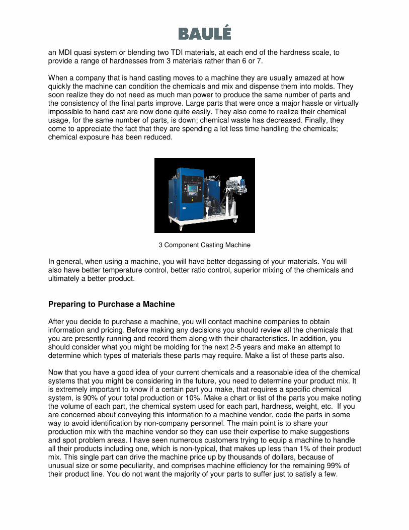
Machine Size and Pump Layout Machines typically come in sizes which are capable of an output range based on the pump sizes, mix head size, hose size, material ratio, and specific gravity of the components. Viscosity of the material at processing temperature should also be considered. The initial design of the machine will try to approximate the ratio of the chemicals with the pump sizes. For example, a chemical system which uses 100 pbw of A, 50 pbw of B, and 10 pbw of C might be equipped with a 20cc pump on the A, a 12 cc on the B, and a 3 cc on the C. This might give you the widest output range with this chemical system. If you want the output to be the highest or lowest amount possible, you might equip the machine to minimize or maximize output without consideration to the opposite extreme.
Cross Section of Typical Gear Pump
Most machines use a fixed output gear type pump. This pump will be rated at an output volume/revolution based on its size. For example, a 3 cc pump will nominally dispense 3 cc of material per every 1 revolution. Depending upon the size of the pump and the manufacturer, the pump will have a recommended minimum and maximum speed of rotation. This range might be 10-250 rpm as an example. This will determine the output range of that pump. Motors are usually sized to handle more than 1 pump size for versatility should a change in ratio occur that cannot be handled by merely changing pump speed. When this happens, the hose size, and material viscosities should be reviewed to determine if a pump change is all that is required.
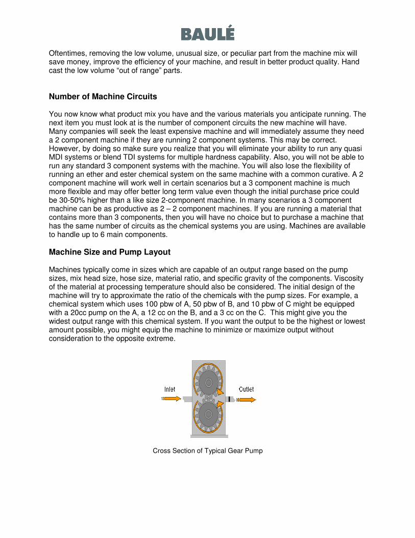
Mix Head and Additive Requirements Mix heads also come in different sizes and configurations to compliment the machines size, number of components, and number of additives. Mix heads are typically designed with variable speed turbine capability, multiple turbine sizes, and different turbine styles to aid in mixing the specific chemical system being used. Mix heads are also designed to operate in a given output range to compliment the machine size purchased. Trying to run below or above the mix head range will oftentimes result in poor mixing or other issues which detract from product quality. The mix head should also have the ability to handle additives such as pigments, catalysts, UV stabilizers, etc. An additive injection unit is recommended for dispensing these products. An additive unit allows you to introduce the additive at the exact rate you desire. If you find you have too much or too little, you merely make an adjustment in the control and the concentration is changed for the next pour. Additive units come in a number of sizes and can supply the additive of your choice at the concentration and output you desire. This allows the molder maximum flexibility and accuracy in processing by allowing the formulation to be adjusted as necessary. Additive units are extremely flexible and offer major advantages over pre-batching; especially where it is difficult to purge a previous material such as carbon black from the circuit. When choosing an additive injection unit, the direct injection method is preferred over the single injector/manifold system. A direct injection system is much faster on additive changeover and decreases material waste when compared with injector systems utilizing a manifold and single injector for all additives. Depending upon the level of machine sophistication chosen, machines can be equipped to include a combination of up to 8 additives; pigments, catalysts, UV stabilizer, anti static, etc. With customization, even more.
Mix Head, Boom, and Additive Units
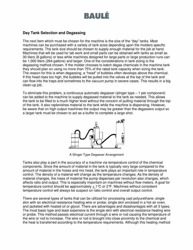
Day Tank Selection and Degassing The next item which must be chosen for the machine is the size of the “day” tanks. Most machines can be purchased with a variety of tank sizes depending upon the molders specific requirements. The tank size should be chosen to supply enough material for the job at hand. Machines that will be used for lab work and small parts can be obtained with tanks as small as 30 liters (8 gallons) or less while machines designed for large parts or large production runs can be 1,000 liters (264 gallons) and larger. One of the considerations in tank sizing is the degassing method chosen. If the molder chooses to batch degas chemicals in the machine tank they should plan on using no more than 75% of the rated tank capacity when sizing the tank. The reason for this is when degassing, a “head” of bubbles often develops above the chemical. If this head rises too high, the bubbles will be pulled into the valves at the top of the tank and can flow into the traps and sometimes to the vacuum pump in severe cases. This results in a big clean-up job. To eliminate this problem, a continuous automatic degasser (slinger type – 1 per component) can be added to the machine to supply degassed material to the tank as needed. This allows the tank to be filled to a much higher level without the concern of pulling material through the top of the tank. It also replenishes material to the tank while the machine is dispensing. However, be aware that on high output machines the output may be greater than the degassers output so a larger tank must be chosen to act as a buffer to complete a large shot.
A Slinger Type Degasser Arrangement
Tanks also play a part in the accuracy of a machine via temperature control of the chemical components. Since the amount of material in the tank is typically very large compared to the amount of material in the hoses and mix head, the tank plays an important role in temperature control. The density of a material will change as the temperature changes. As the density of material changes, the mass of material the pump dispenses per revolution also changes, which affects ratio and output. This is especially important on machines without flow meters. A goal for temperature control should be approximately + 1°C or 2°F. Machines without consistent temperature control will always be suspect on ratio control and overall output control. There are several types of tanks that can be utilized for processing cast polyurethane; single skin with an electrical resistance heating wire or probe, single skin enclosed in a hot air oven, and jacketed with heated oil or glycol. There are advantages and disadvantages with all 3 types. The most basic type and least expensive is the single skin with electrical resistance heating wire or probe. This method passes electrical current through a wire or rod causing the temperature of the wire or rod to increase. The wire or rod is brought into close proximity to the chemical and the heat is transferred according to the temperature requirements. Although this heating method
is inexpensive, it is the least desirable means of controlling temperature and can cause hot spots in the chemical. This method is not recommended for scenarios where the processing temperature must be controlled within a narrow range, such as with certain MDI systems. This method also cannot be recommended where processing temperatures are high; typically >50°C. An agitator is recommended to avoid hot spots in the chemical. The second method utilized is having a single skin tank positioned in a hot air oven. Some people refer to this as the “hot box” method. The strength of this system is that it distributes the heat applied to the chemicals evenly over the entire surface of the tank much the same as a jacketed tank. This method has proven to be very efficient and easy to maintain with processing capabilities to 140°C. The system is also easy to maintain and keep clean. One added advantage is the pump, flow meter, and filters are typically housed in the oven to assure all are at the same temperature. This method is very effective for tanks to 400 liters and above. However, due to the lower heat capacity of air vs. liquid, when considering tanks greater than 400 liters, chemical requirements must be closely examined to make sure the heating times are within the molders requirements. Large tanks with relatively fast heating time requirements may dictate jacketed tanks. An agitator is oftentimes recommended to avoid temperature gradients within the tank. A jacketed tank is a single skin tank enclosed within an outer shell. The shell creates a jacket to pass liquid, typically oil or glycol, over the surface of the tank to temperature condition the chemical. Since liquid has a higher heat capacity than air, a jacketed tank can typically change the temperature of the chemical faster than a hot air oven system. This is most notable on large tanks, >400 liters, where the processing temperature is rather high. It would also be notable if you lowered the temperature significantly during a shut down period or you lost power for several days and the chemical solidified. The draw backs to jacketed tanks are the initial cost, the possibility of having the heating liquid leak into the tank through a weld, leaking fittings or hoses to and from the tank, and maintenance requirements of the heating equipment and heating fluid itself. It is also recommended that an agitator be considered with jacketed tanks.
Agitators There are basically two types of agitators that are used to mix the chemicals in a tank, fixed and variable speed. The fixed speed type is the least expensive. The fixed speed agitator is either on or off and rotates at a steady speed; usually about 50 RPM. This can be changed with different gear ratios (gear box) but is set once the gear ratio is established. The variable speed agitator usually has a variable frequency (speed) drive (VFD) installed on the motor. As the frequency of the power supply is changed through the control system, the RPM of the mixer blade changes. Typically a variable speed agitator will operate between 10RPM and 90RPM. This can be a valuable tool for mixing different types of materials that require different agitation levels.
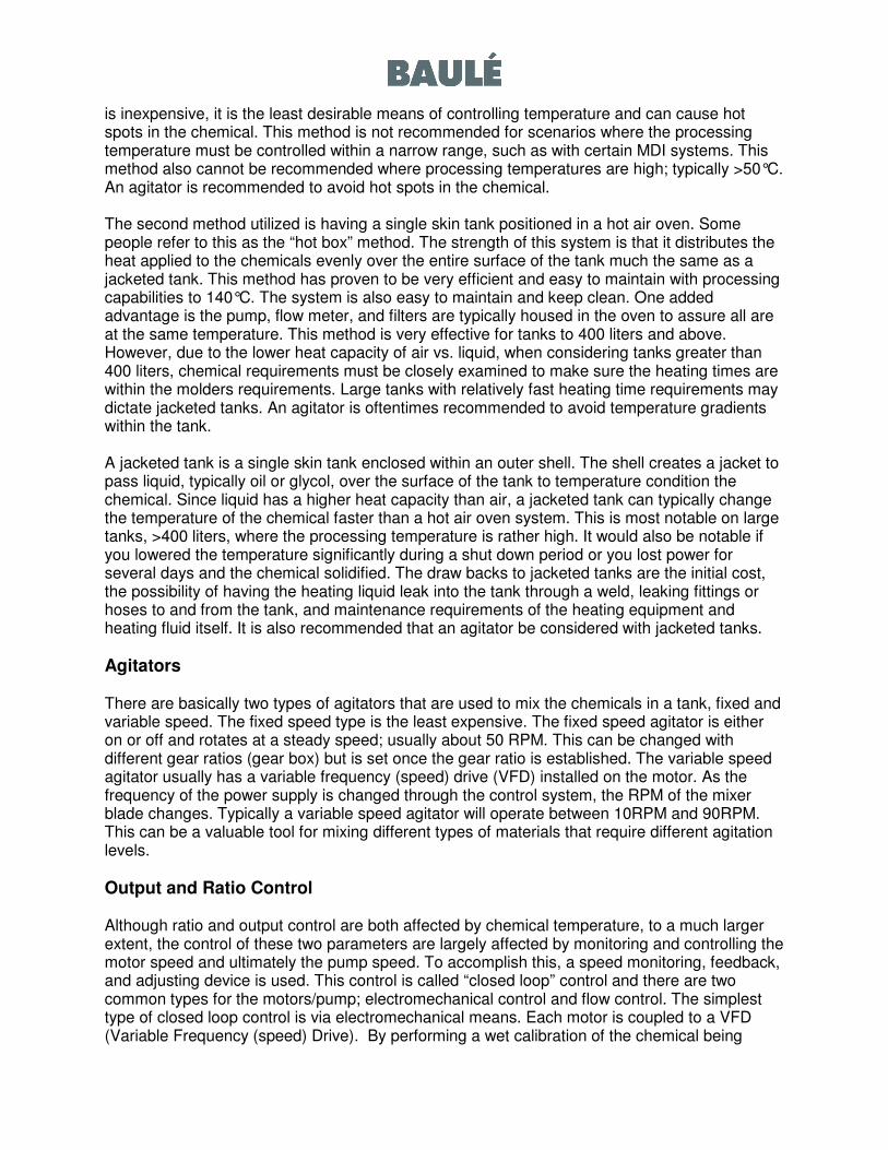
Output and Ratio Control Although ratio and output control are both affected by chemical temperature, to a much larger extent, the control of these two parameters are largely affected by monitoring and controlling the motor speed and ultimately the pump speed. To accomplish this, a speed monitoring, feedback, and adjusting device is used. This control is called “closed loop” control and there are two common types for the motors/pump; electromechanical control and flow control. The simplest type of closed loop control is via electromechanical means. Each motor is coupled to a VFD (Variable Frequency (speed) Drive). By performing a wet calibration of the chemical being
used, the required speed of the pump for a given output is determined with great accuracy and the electronic feedback loop within the VFD holds the rotational speed of the pump within a very narrow RPM range. If the VFD senses the speed changing, for whatever reason, it quickly changes the frequency of electrical current to the motor either increasing or decreasing the speed of the motor/pump assembly. If the pressure and density of the chemical remain relatively constant the output of the chemical will be very close to the preselected value.
Closed Loop Control – Electromechanical (Inner Loop) vs. Flow (outer Loop)
The other means of “closed loop” control is through a flow meter. A flow meter is installed in the circuit on the discharge side of the pump and measures the actual mass flow of the material being dispensed by the pump. If the meter detects a change in the mass flow it sends a signal to the VFD to increase or decrease the motor speed accordingly. Since you are measuring the actual flow of the material you have the ability to correct pump speed in the event the density or viscosity changes in the chemical circuit. For this reason, flow meters can be more accurate than an electro-mechanical closed loop system if the pressure or density fluctuates.
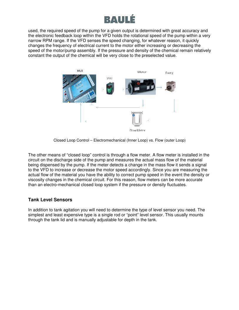
Tank Level Sensors In addition to tank agitation you will need to determine the type of level sensor you need. The simplest and least expensive type is a single rod or “point” level sensor. This usually mounts through the tank lid and is manually adjustable for depth in the tank.
Level Sensor Types and Configuration
A different signal is sent from the sensor when the chemical is either touching or not touching the rod. With these signals the machine manufacturer can provide various options to the end user including stop filling or pouring immediately, finish pour but do not allow another pour, continue operating while giving an alarm signal, etc. A tank can have multiple sensors to accomplish different tasks; filling, low level, and high level. The single point level sensor is extremely reliable. However, one disadvantage with the point level sensor is the operator never really knows the amount of material in the tank unless one of the points is reached. The chemical level can be seen through a viewing point but the amount is not easily determined. A more sophisticated method of level control is with a continuous level sensor. This type of level sensor is a continuous sensor and calibrated at 0% and 100% when the sensor is installed in the tank. A digital readout in % of material left in the tank is displayed. The operator has the ability to change desired levels in the tank from the control panel and knows exactly the amount of usable material in the tank at any given time.
MBOCA Handling, Transfer, and Melting If the molder is using an amine curative such as MBOCA, they have several options. The first option is to load the tank with MBOCA pellets and melt the pellets in the tank by heating the tank to approximately 125°C or above. This method works but is time consuming since it may take up to 12 hours or more to melt the pellets based on tank size, pellet load, and heating capacity. Most molders use a MBOCA melting device and transfer system. This type of system is automated and, depending on MBOCA usage, will fill the MBOCA machine tank with liquid MBOCA according to the specific requirements. A MBOCA melter is a type of grid utilizing hot oil or electrical resistance to heat. The pellets are dropped onto the grid, heated, and melt to a liquid form which the machine can dispense in the proper amount. Some systems transfer the pellets to the machine tank and melt the MBOCA in the machine tank while others use an auxiliary tank to melt the pellets and then transfer the liquid MBOCA to the machine tank. In either case, the preferred method minimizes operator exposure to the MBOCA material.
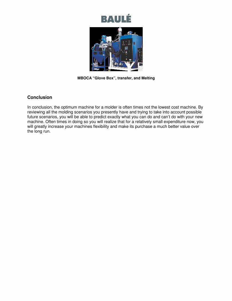
MBOCA “Glove Box”, transfer, and Melting
Conclusion In conclusion, the optimum machine for a molder is often times not the lowest cost machine. By reviewing all the molding scenarios you presently have and trying to take into account possible future scenarios, you will be able to predict exactly what you can do and can’t do with your new machine. Often times in doing so you will realize that for a relatively small expenditure now, you will greatly increase your machines flexibility and make its purchase a much better value over the long run.