Embed Size (px)
Citation preview

2/9/2016
1
Choosing and Commissioning a Video Based Motion Management
System
David ShepardSwedish Cancer Institute
2

2/9/2016
2
3
Acknowledgments
• Daliang Cao, PhD, SCI
• Mohammed Jermoumi, PhD, SCI
• Roger Xie, PhD, SCI
• Malin Kügele, Skåne University Hospital
• Juergen Meyer, University of Washington
• Jonathan Rogers, Alyzen Medical Physics
• Fred Hieronimi - humediQ
4
What’s in a name?
• TG 147 defines photogrammetry as “The extraction of three-dimensional information from data acquired by means of two-dimensional images.”
• Names used to describe this technology: Video based motion management
Surface guided radiotherapy (SGRT)
Surface map imaging
Optical localization

2/9/2016
3
5
Outline
• What is video based motion management?
• What are the potential uses in radiation oncology?
• What commercial solutions exist?
• How to commission and perform ongoing QA?
Video Based Motion Management
• Radiation therapists can view the feed from closed circuit TV cameras
• Problem: Therapists cannot detect small shifts and are multitasking
• Question: Can modern technology improve the utility and accuracy of video based motion management?.
6
2/9/2016
4
Video Based Motion Detection
• In 2010, Microsoft introduced the Xbox Kinect system that enables users to control and interact with their console without the need for a game controller through a natural user interface using gestures.
• It projects a known pattern in near-infrared light. An IR camera observes the scene and the system determines 3D surfaces.
7
8

2/9/2016
5
9
10

2/9/2016
6
How Does X-Box Kinect Work?
11
How does it work?
• The infrared projector is an IR laser that passes through a diffraction grating that turns it into a set of IR dots.
• The relative geometry between the IR projector and IR camera is known as well as the projected dot pattern.
• A 3D image can be recreated using triangulation. 12

2/9/2016
7
Potential Role for Video Based Motion Management Radiation Oncology
• Highly conformal delivery techniques (e.g. IMRT and VMAT) require very accurate patient positioning.
• Cone beam CT (CBCT) has great value but has limitations:– Only a snapshot.
– Does not allow monitoring during treatment
– FOV is limited
– Not helpful for correction of the patient’s posture
– Not useful for respiratory gating
13
How can video based monitoring be used in radiation oncology?
• Positioning: 3D image assists in accurate patient positioning.
• Intrafraction monitoring: Automated detection of changes in patient positioning.
• Respiratory gating: A tool for reducing the impact of respiratory induced tumor motion.
14
Key feature is that video based techniques are non-invasive and non-ionizing.

2/9/2016
8
Commercial Video Based Motion Management Solutions
• C-RAD Catalyst
• VisionRT AlignRT
• humediQ Identify
15
1616
C-RAD Catalyst @ SCI
• Ceiling mounted projector-camera combination
• We have 3 Catalysts systems in our clinic.
• Each Catalyst is interfaced with the Elekta Response gating interface and provides SGRT.

2/9/2016
9
• Projector-Camera Pair
• A sequence of patterns (structured light) is projected onto the surface measured.
• Software compares the projected and captured patterns to identify the coordinates of each pixel on the captured image.
C-RAD Catalyst: Under the Hood
Courtesy of C-RAD 17
• Non-rigid registration:
Courtesy of C-Rad 18

2/9/2016
10
C-RAD Catalyst at SCI
19
Positioning: Patient Setup◦ 3D patient surface used to assist in initial setup
Monitoring: Intra-fraction Patient Motion Monitoring ◦ Live image compared to reference image throughout the
treatment session◦ Out-of-tolerance shifts will trigger audio/visual alarm and can
be setup to automatically pause the beam
Gating: Tracking Patient’s Breathing◦ Signal can be used for gated delivery
Catalyst Modules
20

2/9/2016
11
2121
Patient Setup
• The optical system scans the patient surface and compares it with the reference surface obtained from either the planning CT or BVS setup position.
• Automated couch shifts can be made using connectivity between the Catalyst and the linac.
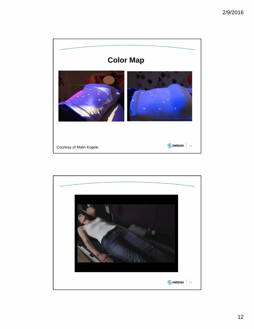
• A color map is projected onto the patient’s skin to indicate areas where the match is poor and to guide the needed changes in positioning.
22
Positioning
Reference imageSurface from CT
Live imagePatient on the couch
Matched ImagesShift determine
System provides shifts in: lat, long, vert, pitch, roll, and yaw
Courtesy of Malin Kügele
2/9/2016
12
Color Map
Courtesy of Malin Kügele 23
24

2/9/2016
13
25
Patient Positioning
Patient’s arms not in the correct position.
Breast position in
longitudinal direction not
within tolerance.
Courtesy of Malin Kügele
Surface Map Imaging for Positioning
• Reduces risk of making an incorrect shift• Provides extra check for a missed bolus• Good check of arm position and breast board
angle for breast patients• Necessitates exposed skin in the treatment area
Courtesy of Malin Kügele 26

2/9/2016
14
27
Limitations
• Deep targets (lack of correlation with surface)
• Surfaces that move significantly (abdomen)
• Shadows
• Provides real-time motion monitoring
• No additional radiation dose
• Millimeter sensitivity (much better than CCTV)
• When motion threshold is exceeded it can trigger audio/visual alarm or automatically pause delivery
28
Intrafraction Patient forMotion Monitoring

2/9/2016
15
• A red gating point can be placed at any position on the patient.
• Point size / radius is adjustable.
• A secondary point can be placed on the patient for additional information.
• Amplitude given in absolute numbers.
Respiratory Gating
Courtesy of Malin Kügele29
Respiratory Gating: C‐Rad Catalyst
30

2/9/2016
16
• The patient breathes as instructed:
– Audio
– Video
• Patient is coached to breathe with chest and not abdomen.
Respiratory Gating
Courtesy of Malin Kügele31
Gating Workflow
• Example “Breath hold”:Audio-Visual Feedback – Patient View
Respiration Target
Respiration Signal
Baseline
Exhale Phase(treatment beam off)
Inhale Phase(treatment beam on)
32

2/9/2016
17
Gated Beam Delivery
Exception Gating
Free Breathing Gating
Breath hold gating
33
Catalyst Respiration Tracking/Gating: Visualized on A Phantom
34

2/9/2016
18
Clinical Case with Catalyst:Tracking of Free Breathing SBRT
35
Primary gatingspot
0
5
10
15
20
25
30
35
40
0 20 40 60 80 100 120 140 160
Amplitude [m
m]
Time [s]
Breathing amplitude for Catalyst and RPM.
Cata
RPM
Gating: Catalyst vs. RPM
From: Sofie Ceberg och Charlotte Thornberg

2/9/2016
19
• Delivery window coincides with ABC breath hold.
Catalyst Tracking on an ABC Gated Left Breast Patient
37
• Device utilizing a laser scanning galvanometer and a video camera installed in a single ceiling mounted package.
• The scanning laser passes over the patient's surface and the apparent deformation of the laser line is used to render the surface.
• The surface position is compared to a reference surface to determine the patient’s offset.
• Sentinel is installed in our CT simulation room.
• Used for 4DCT.
• Used to train patients on respiratory gating/DIBH and used in acquired gated CT images.
C-RAD Sentinel
38

2/9/2016
20
The C‐RAD Sentinel system acquires surface map images using which of the following:
20%
20%
20%
20%
20% 1. Scanning laser
2. Infrared cameras
3. Video cameras with projected light pattern
4. Implanted beacons with an RF panel
5. Spirometry
10
• Answer: Scanning laser
• Reference: S. Pallotta, L. Marrazzo, M. Ceroti, P. Silli, and M. Bucciolini, “A phantom evaluation of Sentinel, a commercial laser/camera surface imaging system for patient setup verification in radiotherapy,” Med. Phys. 39, 706–712 (2012).

2/9/2016
21
VisionRT AlignRT
• Uses stereoscopic video images in combination with patterns it projects onto the patient (structured light) to dynamically capture and reconstruct maps of the patient’s surface.
41
VisionRT AlignRT
• More than 600 AlignRT systems have been ordered worldwide
• Installed in 37 of top 50 cancer centers (as ranked by US News)
• It is part of the package provided with the Varian Edge model
42

2/9/2016
22
© 2016 Vision RT Ltd
SURFACE GUIDED RADIOTHERAPY : PRINCIPLES
– Uses near infrared light– Projects a pseudo random speckle pattern– Matches all possible corresponding points– Produces 3D triangulated mesh– Maps out approx. 20,000 3D points
of the patients anatomy
© 2016 Vision RT Ltd
USER INTERFACE: EXAMPLE

2/9/2016
23
© 2016 Vision RT Ltd
ALIGNRT: ACCESSORIES*
Head adjusterAllows corrections of pitch, yaw and roll head rotations Adjustments to within a tenth of a degreeBolts on with quick release clamps to standard couch tops
Real-time coachContactless breath hold coaching: for DIBH
© 2016 Vision RT Ltd
FRAMELESS SRS: BENEFITS
Patient comfort: Open mask = reduced claustrophobia, non-invasive
Safety: Continuous monitoring of any motion underthe mask in real time
Accuracy: <1mm
Efficiency: Frameless SRS on conventional Linac
Application: Can specify tracking region to avoid mask and increase accuracy

2/9/2016
24
© 2016 Vision RT Ltd
PATIENT SETUP DEEP INSPIRATION BREATH-HOLD (DIBH)
IMRT Chest wall
Multiple ROIs
Real time tracking of breast during Deep Inspiration Breath Hold
CLINICAL APPLICATIONS: BREAST
humediQ Identify
• Uses a medical RFID reader to automatically recognize each patient and the accessories while they’re being positioned on the treatment couch.
• Two stereoscopic cameras use TOF imaging to create 3D surface map. 48

2/9/2016
25
RFID to Check Accessories and Patient ID
Headrest – JonathanVacuum Cushion – JonathanKneeSTEP 8B
49
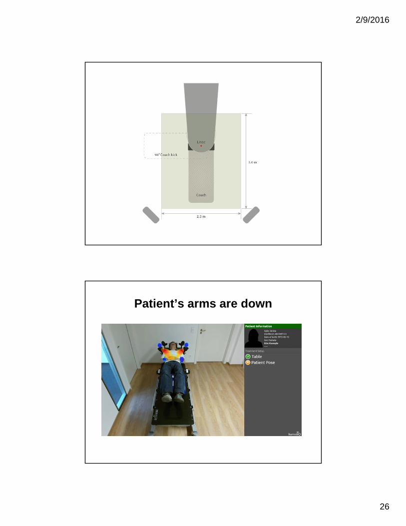
humediQ IdentifyGeneral Functionality
• Dual camera systemo Time of flight and optical HD)
• RFID system for tracking patient ID and accessories.
• Patient virtual surface from the simulation is shown [on the wall screen and ceiling screen].
• Patient self-positioning guidance.• For gating, a gating marker is placed on
patient surface.
50
2/9/2016
26
Patient’s arms are down

2/9/2016
27
Patient is shifted to the right
Patient is shifted to the left

2/9/2016
28
Features of the surface map imaging include all of the following except:
20%
20%
20%
20%
20% 1. Images are 3D in nature
2. Uses radiofrequency tracking to track implanted markers
3. Imaging is non-ionizing and non-invasive
4. The patient’s posture can be visualized
5. Provides real-time feedback and can be used to monitor motion
10
• Answer: radiofrequency tracking is used by the Calypso system.
• Reference: “Quality assurance for nonradiographic radiotherapy localization and positioning systems: report of Task Group 147”, Med Phys, 39 (2012), pp. 1728–1747
Features of the surface map imaging include all of the following except:

2/9/2016
29
57
Considerations in Picking a Video Based Motion Monitoring System
• Determine your clinical need:– What disease sites will be treated the most often?
– How will it be used: positioning, motion-management, and/or respiratory gating?
• Talk to current customers. Find customers with a similar configuration (Linac, EMR, TPS)
• Cost
Acceptance Testing, Commissioning, and QA of Your Video Based Monitoring System
58

2/9/2016
30
Acceptance Testing (TG-147)
• Demonstrates that the equipment is meeting the specifications in the purchase contract between the facility and the vendor.
• Vendor must demonstrate localization consistent with the recommendations of TG-142, within 2mm for conventional delivery and 1mm for SRS/SBRT.
• Test connectivity between systems (e.g. EMR, TPS, treatment couch).
59
Commissioning and QA
• Start with your planned clinical utilization to establish QA procedures in conjunction with TG-147 recommendations.
– What disease sites will be treated the most often?
– Will it be used for positioning, motion-management, and/or respiratory gating?
– What tolerances will be needed during positioning and during motion monitoring?
• Prioritize your QA in terms of clinical need
60Courtesy of Jonathan Rogers

2/9/2016
31
61
Commissioning and QA
62
Commissioning:Integration of Peripheral Equipment
• Check data transfer from simulation, treatment planning, and the record-and-verify system in different orientations (head first, feet first, prone, supine, etc.).
• Check communication– Auto loading of patient information by surface mapping software
– Automated couch repositioning
– Automated beam interruption and impact on delivery accuracy
• The localization field of view should be measured and documented.

2/9/2016
32
63
Commissioning:Spatial Reproducibility and Drift
• Stability testing should be performed during the commissioning of a localization system by monitoring and recording a test pattern for at least 90 minutes or until sufficient stability is achieved.
• Safeguards or procedures should be developed to prevent clinical use during the camera warm up time.
• Reproducibility can be measured by the same device for an additional 60 minutes after establishing stability.
• Test should be done annually or after equipment changes or per manufacturer specifications.

2/9/2016
33
65
Commissioning:Spatial Reproducibility and Drift
0
0.1
0.2
0.3
0.4
0.5
0.6
0.7
0.8
0 50 100 150
3D d
isp
lace
men
t (
mm
)
Time after power Up (min)
66
Commissioning:Static Localization Accuracy
• Localization displacement accuracy should be checked over a range that covers all clinical shifts to be expected for the system.
• Recommendation is that that at least 10cm shifts from isocenter or between two isocenters should be checked in all directions.
• Overall system accuracy should be measured using an end-to-end target test. This is typically performed using a phantom that has embedded radiographic markers visible on both CT and kV or MV imaging.

2/9/2016
34
67Maximum measured deviation 2mmMaximum measured rotation was 1
Deviation (cm)
Shift (cm) Lat (cm) Long (cm) Vert (cm)
1 -0.1 -0.1 02 -0.1 -0.1 03 -0.1 0 04 0 0 -0.15 -0.1 -0.1 -0.16 0 -0.1 -0.1-1 0.2 0 -0.1-2 0.1 -0.1 0-3 0 0 0-4 0.1 0 0-5 0.1 0 -0.1-6 0 -0.1 0
Accuracy of Shifts
• Map out your workflow and establish an end-to-end test that incorporates the complete process:
68Courtesy of Jonathan Rogers

2/9/2016
35
• Create a test that mimics the clinical use case (E2E):
69Courtesy of Jonathan Rogers
70
End-to-end TestHidden Target Test
• Phantom marked with exterior visual cues for initial setup.
• A treatment planning CT is performed.
• Scans are sent to TPS where an isocenter can be defined relative to the location of the hidden target.
• At the linac, the phantom is positioned arbitrarily relative to the isocenter and surface map imaging is used restore the hidden target to the isocenter or its planned location relative to the isocenter.
• Imaging is performed to identify target localization accuracy relative to the machine’s radiation isocenter.

2/9/2016
36
71
Commissioning:Dynamic Localization Accuracy
• If you are performing real-time patient tracking, testing should be performed with a 4D phantom.
• The accuracy during tracking is the difference between the phantom’s programmed location and the measured location via surface map imaging.
• For example, you can program the phantom to move 1cm and stay at each location for 5 seconds.
72
Dynamic Localization Accuracy Test

2/9/2016
37
73
CIRS Phantom Catalyst
Amplitude (mm) Period (ms) Amplitude (mm) Period (ms)
4 5000 3.87 5120
8 5000 7.96 5099
16 5000 15.81 5260
24 5000 23.79 5172
32 5000 31.51 5013
40 5000 39.46 5171
Maximum difference for amplitudes and periods are 0.54 mm and 260 ms respectively
74
Commissioning:Dynamic Localization Accuracy (2)
• Tests should be performed to evaluate any delay (latency) between the time a patient moves and when the localization system identifies the motion.
• Best performed using a motion phantom.
• Additionally use the motion phantom to test the beam-hold mechanism that is employed when the patient moves beyond the specified tolerance. Delivered dose should be within 2% of radiation delivery without gating.
2/9/2016
38
75
Daily QA
• The agreement between the localization system isocenter and the treatment isocenter should be evaluated on the days that the system is used.
• The daily QA phantom should be recognized by the localization system as being within 2mm of the isocenterwhen it is positioned based upon the lasers.
• Motion tracking should be tested by moving the phantom a known amount (e.g. 5cm) and checking that the localization system indicates the correct shift within 2mm.
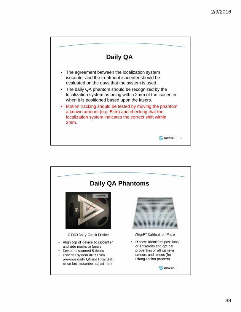
AlignRT Calibration Plate
• Process identifies positions, orientations and optical properties of all camera sensors and lenses (for triangulation process)
Daily QA Phantoms
C-RAD Daily Check Device
• Align top of device to isocenterand side marks to lasers
• Device is scanned 5 times• Provides system drift from
previous daily QA and total drift since last isocenter adjustment

2/9/2016
39
77
Monthly QA
• A localization accuracy test which relates the localization system directly to the treatment isocenter should be performed using films or portal imaging devices to verify alignment.
• Localization accuracy should be within 2mm of isocenterfor standard fractionations and 1mm for SRS/SBRT.
• Evaluate tracking accuracy of the system.
QA Equipment
• Isocenter calibration phantom– Used for correlating the MV isocenter to the surface
imaging isocenter
– No dosimetric capabilities
• Any imaging SRS phantom (like MaxHD)– Surface can be imaged
– Gafchromic, pinpoint chamber, and/or OSL inserts
– Capable of full end-to-end testing
– Hidden target testing verifies radiation isocenter
78Courtesy of Jonathan Rogers

2/9/2016
40
• Calibration to MV isocenter
• Allows verification of kV, AlignRT and laser isocenters
• Allows high accuracy tracking of surface at all couch rotations
Calibration Phantom*
Align RT QA Phantoms
79
80
Annual QA
• Camera stability
• Compare actual and predicted shifts over a range of distances.
• 4D/motion phantom to test accuracy of beam gating.
• Test data transfer for at least two patient/device configurations (head first supine, head first prone, etc.)
• A full end-to-end test from CT through treatment

2/9/2016
41
Frozen Turkey: Breast Isocenter Defrosted Turkey: Breast Isocenter
CBCT to Verify Surface Mapping Set-up to Breast Isocenter
81
CBCT to Verify Surface Mapping Set up to Paraspinal Isocenter
Frozen Turkey: Paraspinal Isocenter Defrosted Turkey: Paraspinal Isocenter
82

2/9/2016
42
Frozen TurkeyDefrosted
Turkey
Near-Spine Isocenter
<2mm shifts in alldirections
~10mm shifts
Near-Surface Isocenter
<2mm shifts in alldirections
<2mm shifts in alldirections
• SGRT maintains its accuracy when the treatment isocenter is closer to the detected surface even when the body shaped is deformed.
• Surface mapping is less accurate for treatment sites deep inside the body when body deformation occurs.
83
According to Task Group 147, which of the following tests should be performed daily on non-radiographic
radiotherapy localization and positioning systems (e.g. surface map imaging systems)?
20%
20%
20%
20%
20% 1. Positioning accuracy
2. End-to-end
3. Camera stability
4. Static localization
5. Winston-Lutz
10

2/9/2016
43
• Answer: Static localization
• Reference: “Quality assurance for nonradiographic radiotherapy localization and positioning systems: report of Task Group 147”, Med Phys, 39 (2012), pp. 1728–1747
According to Task Group 147, which of the following tests should be performed daily on non-radiographic
radiotherapy localization and positioning systems (e.g. surface map imaging systems)?
Gating Performance Test
• A MatriXX ion-chamber array mounted on a QUASAR Programmable Respiratory Motion Platform– 6MV, 100MU, 10x10cm2 field to a stationary MatriXX
– The same field was then delivered with the MatriXX platform programmed to move between -2 and +2 cm longitudinally.
– Gating signal was provided by Catalyst tracking a vertical-moving chest plate on QUASAR
– Gating windows were set between 10% and 100% at 10% increments.
86

2/9/2016
44
Quasar Respiratory Motion Platform
87
Results: Dose Distribution, Line Profile, Gamma Map
88

2/9/2016
45
-10 -5 0 5 10-10
0
10
20
30
40
50
60
70
80
90
100
110
Do
se (
cGy)
Position (cm)
Stationary Phantom 100% Beam On 50% Gating Window 30% Gating Window 10% Gating Window
Results: Line Profile Comparison
89
Results: Gating Window vs. Gamma Rates and Delivery Time
0 2 0 4 0 6 0 8 0 1 0 08 2
8 4
8 6
8 8
9 0
9 2
9 4
9 6
0 2 0 4 0 6 0 8 0 1 0 00
5 0
1 0 0
1 5 0
2 0 0
2 5 0
Tim
e o
f D
eliv
ery
(s)
Gam
ma
Pas
sin
g R
ate
(%)
G a t in g W in d o w (% )
90

2/9/2016
46
91
Conclusions
• SGRT is gaining wider acceptance and has the potential to significantly reduce the frequency of positioning errors in radiation oncology.
• It facilitates monitoring the patient’s motion during the treatment and can be used for respiratory gating.
• TG147 provides guidance for commissioning and QA.
![Template for Electronic Submission to ACS Journalseprints.whiterose.ac.uk/117925/1/acs_catal_FAIRLAMB_r3_v... · Web viewThis can be overcome using pre-synthesised [Ar1IAr2]X salts](https://img.pdfslide.net/doc/110x75/60d4c4b3f8467e2dc42ce3a3/template-for-electronic-submission-to-acs-web-view-this-can-be-overcome-using-pre-synthesised.jpg)