Embed Size (px)
Citation preview

Available online at www.sciencedirect.com
www.elsevier.com/locate/actamat
Acta Materialia 57 (2009) 335–344
Chromium carbide–CNT nanocomposites with enhancedmechanical properties
Virendra Singh a, Rene Diaz a, Kantesh Balani b, Arvind Agarwal b, Sudipta Seal a,*
a Plasma Nanomanufacturing Facility, Advanced Materials Processing and Analysis Center, Mechanical Materials Aerospace Engineering,
Nanoscience and Technology Center, Engineering Building, Room #381, P.O. Box 162455, University of Central Florida, Orlando, FL 32816, USAb Mechanical and Materials Engineering, Florida International University, Miami, FL 33174, USA
Received 3 September 2008; accepted 7 September 2008Available online 22 October 2008
Abstract
Chromium carbide is widely used as a tribological coating material in high-temperature applications requiring high wear resistanceand hardness. Herein, an attempt has been made to further enhance the mechanical and wear properties of chromium carbide coatings byreinforcing carbon nanotubes (CNTs) as a potential replacement of soft binder matrix using plasma spraying. The microstructures of thesprayed CNT-reinforced Cr3C2 coatings were characterized using transmission electron microscopy and scanning electron microscopy.The mechanical properties were assessed using micro-Vickers hardness, nanoindentation and wear measurements. CNT reinforcementimproved the hardness of the coating by 40% and decreased the wear rate of the coating by almost 45–50%. Cr3C2 reinforced with2 wt.% CNT had an elastic modulus 304.5 ± 29.2 GPa, hardness of 1175 ± 60 VH0.300 and a coefficient of friction of 0.654. It was con-cluded that the CNT reinforcement increased the wear resistance by forming intersplat bridges while the improvement in the hardnesswas attributed to the deformation resistance of CNTs under indentation.� 2008 Acta Materialia Inc. Published by Elsevier Ltd. All rights reserved.
Keywords: Plasma spraying; Nanoindentation; Hardness test; Coatings; Wear
1. Introduction
Carbides are high-strength materials. Excellent mechan-ical properties and durability of carbides have made them amaterial of choice in applications involving extreme tem-perature and pressure, e.g., rocket nozzles, drill bits, cut-ting tools, golf shoe spikes and snow tires [1]. Primarilyrefractory carbides of the transition metals of the fourthto sixth groups of the periodic table, including the carbidesof tungsten, titanium, tantalum and chromium, are used inthese demanding applications [2]. In particular, chromiumcarbides (Cr3C2) demonstrate excellent strength, hardness,anti-erosion and corrosion properties, permanent non-magnetizability and surface illustriousness [2]. As a result,chromium carbide-type materials have been widely used
1359-6454/$34.00 � 2008 Acta Materialia Inc. Published by Elsevier Ltd. All
doi:10.1016/j.actamat.2008.09.023
* Corresponding author. Tel.: +1 407 882 1119; fax: +1 407 882 1156.E-mail address: [email protected] (S. Seal).
in a variety of industrial applications, such as shaft bear-ings, seals, high-temperature furnaces, nozzles and metalmachining molds [3]. It has the potential to be an environ-mentally friendly replacement for conventional electro-chemical hard chrome plating [4]. Despite chromiumcarbide’s excellent wear- and corrosion-resistant proper-ties, it is not used as a primary carbide in industry owingto its lower hardness in comparison to other carbides (suchas tungsten carbide). Several attempts have been made toimprove the hardness and wear property of chromium car-bide coatings by varying the coating techniques, processingparameters and characteristics of the feedstock powder[5–8]. Popular techniques, such as detonation gun(D-gun) and high-velocity oxy-fuel (HVOF), use Ni–Cras a binder and are primarily low-temperature, high-depo-sition velocity processes. These processes can increase thedensity (up to 98%) of the coating and improve the wear,adhesion and mechanical properties moderately [8–10].
rights reserved.

Fig. 1. SEM image of as-received Cr3C2 powder, showing its irregularshape and surface porosities (inset). The SEM image of blended Cr3C2 andCNTs powder shows CNTs inside the pores of Cr3C2 particles.
336 V. Singh et al. / Acta Materialia 57 (2009) 335–344
Cr3C2–20–25% NiCr cermets are used for wear-resistantcoatings, where the NiCr acts as a soft binder metal matrixfor the hard chromium carbide particles. The binder phaseoften dissolves carbide phase during deposition, recrystal-lizes and oxidizes upon exposure to the high-temperatureapplications, subsequently lowering the hardness and wearresistance of the coating [11,12]. However, the mechanicalproperties of chromium carbide can be improved by rein-forcement with a second phase, which can further improvethe fracture toughness by crack bridging. One possiblematerial that can be used for this is carbon nanotubes(CNTs). As stated in the literature, CNTs have remarkablemechanical, electrical and thermal properties [13–18], andcan be a potential replacement of soft metal binders in car-bide coatings. Depending on their length and diameter, chi-rality and orientations, CNTs exhibit almost five times theelastic modulus (�1 TPa) and nearly 100 times the tensilestrength (�150 GPa) of high-strength steels [18–21].Multi-walled CNTs have already shown successful inclu-sion in and enhancement of the mechanical properties ofplasma-sprayed Al–Si nanocomposites [22], alumina(Al2O3) [23], magnesium nanocomposites [24] andplasma-sprayed hydroxyapatite ceramic coatings, wherefracture toughness is enhanced by 50–60% [25]. It has beendemonstrated that CNT-reinforced nanocomposites exhi-bit three ways of toughening: crack deflection at theCNT/matrix interface; crack bridging by CNTs; andCNT pullout on the fracture surfaces [26].
In the present study CNT-reinforced chromium carbidecoating was prepared via the air plasma spray (APS)process. Chromium carbide feedstock was blended with1–2 wt.% CNTs as a potential replacement for soft metalbinder. These composite coatings are characterized interms of their microstructures and mechanical properties.Transmission electron microscopy (TEM) studies confirmthe retention of CNTs in the coating. Effects of CNT rein-forcement on wear and the coefficient of friction (COF) arecorrelated to the enhanced hardness and elastic modulus ofthe CNT-reinforced nanocomposite.
2. Experimental details
2.1. Powder processing
Pre-processed plasma spray grade 99.8% irregular chro-mium carbide powder (particle size 45–100 lm) was usedfor composite coating (from AAE, Bergenfield, NJ).Multi-walled CNTs (MWCNTs; outer diameter = 10–15 nm, inner diameter = 2–6 nm, length = 0.1–10 lm,>90% purity) were obtained from Sigma–Aldrich. Cr3C2
powder was blended with the CNTs at varying weight per-centages through jar mill for 7 days to obtain a homoge-neous mix and break up any agglomerates of the CNTs.Three powder batches were used for experimentation:chromium carbide (Cr3C2) as control, Cr3C2–1 wt.%CNT and Cr3C2–2 wt.% CNT. Powder morphology beforeand after mixing with CNTs is shown in Fig. 1.
2.2. Plasma spraying
Air plasma spraying (APS) of Cr3C2 with and withoutCNTs was carried out using a Praxair SG 100 gun. Thespray processing parameters are listed in Table 1. Powderswere injected internally in the plasma spray gun (SG100)using argon as a carrier gas to deposit coatings on a steelsubstrate. Hydrogen gas was used as a secondary gas toincrease the enthalpy of the plasma plume. Optimumplasma parameters were obtained by varying the powderflow rate, carrier gas flow, primary and secondary gas flowrates, standoff distance and power input to increase thedensity of the coating. Prior to coating, steel substrateswere grit-blasted with alumina particles (40 grit size) inorder to increase the roughness of the surface to allow bet-ter adhesion of splats to form a dense coating.
2.3. Structural and microstructural characterization
A comprehensive microstructural evaluation of theplasma spray-formed Cr3C2–CNT was carried out usingscanning electron microscopy (SEM; JEOL 6400F) onthe surface and cross-section of the coating. The porosityof the cross-section of the coatings was calculated usingimage analysis software (IQmaterials 2.0 Software). X-raydiffraction (XRD; Rigaku D-Max B diffractometer) pat-terns were recorded from both powders and the coated sur-faces of chromium carbide and Cr3C2–CNT composites.The X-ray diffractometer was set at 40 kV and 30 mA witha Cu Ka radiation target (k � 1.54 A). The diffraction pat-terns were recorded at a speed of 1� min�1. In order toinvestigate the retention of CNTs in the coating and nano-crystalline grain formation, a high-resolution transmissionelectron microscope (Tecnai F30) was used with a fieldemission gun (FEG) operating at a voltage of 300 kV. ATEM sample of the composite coating was prepared byconventional mechanical grinding of the coating to a thick-ness of 50 lm. Final thinning to electron transparency was
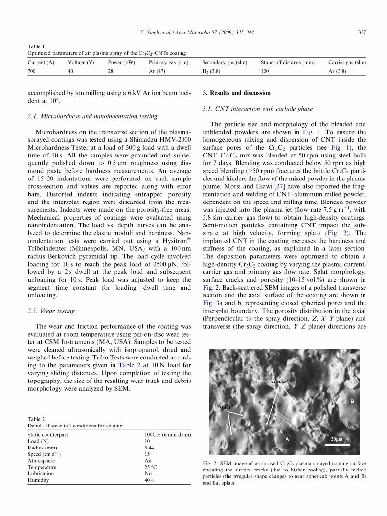
Table 1Optimized parameters of air plasma spray of the Cr3C2–CNTs coating
Current (A) Voltage (V) Power (kW) Primary gas (slm) Secondary gas (slm) Stand-off distance (mm) Carrier gas (slm)
700 40 28 Ar (47) H2 (3.8) 100 Ar (3.8)
V. Singh et al. / Acta Materialia 57 (2009) 335–344 337
accomplished by ion milling using a 6 kV Ar ion beam inci-dent at 10�.
2.4. Microhardness and nanoindentation testing
Microhardness on the transverse section of the plasma-sprayed coatings was tested using a Shimadzu HMV-2000Microhardness Tester at a load of 300 g load with a dwelltime of 10 s. All the samples were grounded and subse-quently polished down to 0.5 lm roughness using dia-mond paste before hardness measurements. An averageof 15–20 indentations were performed on each samplecross-section and values are reported along with errorbars. Distorted indents indicating entrapped porosityand the intersplat region were discarded from the mea-surements. Indents were made on the porosity-free areas.Mechanical properties of coatings were evaluated usingnanoindentation. The load vs. depth curves can be ana-lyzed to determine the elastic moduli and hardness. Nan-oindentation tests were carried out using a Hysitron�
Triboindenter (Minneapolis, MN, USA) with a 100 nmradius Berkovich pyramidal tip. The load cycle involvedloading for 10 s to reach the peak load of 2500 lN, fol-lowed by a 2 s dwell at the peak load and subsequentunloading for 10 s. Peak load was adjusted to keep thesegment time constant for loading, dwell time andunloading.
2.5. Wear testing
The wear and friction performance of the coating wasevaluated at room temperature using pin-on-disc wear tes-ter at CSM Instruments (MA, USA). Samples to be testedwere cleaned ultrasonically with isopropanol, dried andweighed before testing. Tribo Tests were conducted accord-ing to the parameters given in Table 2 at 10 N load forvarying sliding distances. Upon completion of testing thetopography, the size of the resulting wear track and debrismorphology were analyzed by SEM.
Table 2Details of wear test conditions for coating
Static counterpart 100Cr6 (6 mm diam)Load (N) 10Radius (mm) 5.44Speed (cm s�1) 15Atmosphere AirTemperature 25 �CLubrication NoHumidity 40%
3. Results and discussion
3.1. CNT interaction with carbide phase
The particle size and morphology of the blended andunblended powders are shown in Fig. 1. To ensure thehomogeneous mixing and dispersion of CNT inside thesurface pores of the Cr3C2 particles (see Fig. 1), theCNT–Cr3C2 mix was blended at 50 rpm using steel ballsfor 7 days. Blending was conducted below 50 rpm as highspeed blending (>50 rpm) fractures the brittle Cr3C2 parti-cles and hinders the flow of the mixed powder in the plasmaplume. Morsi and Esawi [27] have also reported the frag-mentation and welding of CNT–aluminum milled powder,dependent on the speed and milling time. Blended powderwas injected into the plasma jet (flow rate 7.5 g m�1, with3.8 slm carrier gas flow) to obtain high-density coatings.Semi-molten particles containing CNT impact the sub-strate at high velocity, forming splats (Fig. 2). Theimplanted CNT in the coating increases the hardness andstiffness of the coating, as explained in a later section.The deposition parameters were optimized to obtain ahigh-density Cr3C2 coating by varying the plasma current,carrier gas and primary gas flow rate. Splat morphology,surface cracks and porosity (10–15 vol.%) are shown inFig. 2. Back-scattered SEM images of a polished transversesection and the axial surface of the coating are shown inFig. 3a and b, representing closed spherical pores and theintersplat boundary. The porosity distribution in the axial(Perpendicular to the spray direction, Z, X–Y plane) andtransverse (the spray direction, Y–Z plane) directions are
Fig. 2. SEM image of as-sprayed Cr3C2 plasma-sprayed coating surfacerevealing the surface cracks (due to higher cooling), partially meltedparticles (the irregular shape changes to near spherical; points A and B)and flat splats.

Fig. 4. Porosity distribution with aspect ratio in the coating (a) axialdirection, i.e., perpendicular to spray direction, and (b) transversedirection, i.e., the spray direction, showing a higher aspect ratio becauseof the interlamellar boundary. The distribution of porosity is representedon a 180� spread with respect to aspect ratio.
Fig. 3. Back-scattered SEM images of chromium carbide coating. (a)Cross-section, showing the lamellar structure of the chromium carbidedeposit. Curved black lines show the interlamellar boundary, black spotsshow the porosity generated during deposition. (b) SEM image of thepolished coating surface viewed from the top, showing fine cracks and theclosed porosities revealed after removal of the surface irregularities.
338 V. Singh et al. / Acta Materialia 57 (2009) 335–344
shown in Fig. 4a and b, respectively. A higher concentra-tion of high-aspect-ratio porosity was found in the trans-verse direction. This indicates that the entrappedinterlamellar pores were formed due to the incomplete fill-ing of the pores by successive molten layers along the axialdirection and the intersplat boundary region. The mea-sured porosity of the coating was 10–15 vol.%. This isattributed to the partial melting and decarburization ofthe chromium carbide particles in the high-temperaturezone of the plasma. Furthermore, the present study doesnot use the binder metal. In general, 20–35% of NiCr isused as a binder phase in coatings of chromium carbide,which increases the density and toughness of the coating[9,28]. However, in the present study we have improvedthe hardness (by 40%) and abrasive wear properties ascompared to that of unreinforced Cr3C2 coating usingplasma spray by incorporating only 2 wt.% CNTs. Thisconfirms that the high strength of MWCNTs can play avital role in augmenting the mechanical properties of thecoating without the addition of a high percentage of binderphases.
3.1.1. Morphological evaluation: transmission electron
microscopy (TEM)
The high-resolution transmission electron microscopy(HRTEM) image of the Cr3C2–2 wt.% CNT coating(Fig. 5) and the SEM image of the fractured surface(Fig. 6) corroborate the presence of undamaged CNT inthe Cr3C2 matrix after spraying. Fig. 5 depicts the undam-aged CNT and splat bonding where the CNT acts as abridge between the splats. The bridging between the splatsrestricts any intersplat sliding movement and improves thetoughness of the coating [29]. The excellent coverage of thechromium carbide matrix with CNT enhances the loadtransfer properties from the Cr3C2 splat to the CNT. TheHRTEM image shown in Fig. 7 shows the CNT–chromiumcarbide interface with nanograins of carbide matrixattached to the CNT. The adjoining chromium carbidenanograins have lattice spacing of 2.24 A (inset C), whichcorresponds to the interplaner spacing of the plane (203)of Cr3C2 [9,10]. The presence of nanograins is attributedto the extremely high cooling rate (106–108 K s�1) duringthe solidification of the molten carbide. Points A and Bin the HRTEM image (Fig. 7) show the fused layer ofthe CNT and the carbide matrix. Absence of the lattice
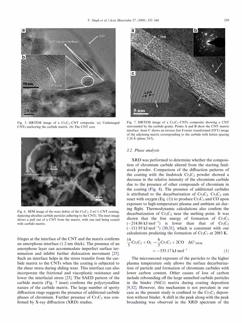
Fig. 7. HRTEM image of a Cr3C2–CNTs composite showing a CNTsurrounded by the carbide grains. Points A and B show the CNT–matrixinterface. Inset C shows an inverse fast Fourier transformed (FFT) imageof the adjoining matrix corresponding to the carbide with lattice spacing2.24 A (plane 203).
Fig. 5. HRTEM image of a Cr3C2–CNT composite. (a) UndamagedCNTs anchoring the carbide matrix. (b) The CNT core.
Fig. 6. SEM image of the wear debris of the Cr3C2–2 wt.% CNT coating,depicting ultrafine carbide particles adhering to the CNTs. The inset imageshows a pull out of a CNT from the matrix, with one end being coatedwith carbide matrix.
V. Singh et al. / Acta Materialia 57 (2009) 335–344 339
fringes at the interface of the CNT and the matrix confirmsan amorphous interface (1.2 nm thick). The presence of anamorphous layer can accommodate imperfect surface ter-mination and inhibit further dislocation movement [23].Such an interface helps in the stress transfer from the car-bide matrix to the CNTs when the coating is subjected tothe shear stress during sliding wear. This interface can alsoincorporate the frictional and viscoplastic resistance andlower the interfacial stress [23]. The SAED pattern of thecarbide matrix (Fig. 7 inset) confirms the polycrystallinenature of the carbide matrix. The large number of spottydiffraction rings suggests the presence of additional carbidephases of chromium. Further presence of Cr7C3 was con-firmed by X-ray diffraction (XRD) studies.
3.2. Phase analysis
XRD was performed to determine whether the composi-tion of chromium carbide altered from the starting feed-stock powder. Comparison of the diffraction patterns ofthe coating with the feedstock Cr3C2 powder showed adecrease in the relative intensity of the chromium carbidedue to the presence of other compounds of chromium inthe coating (Fig. 8). The presence of additional carbidesis attributed to the decarburization of Cr3C2. Cr3C2 canreact with oxygen (Eq. (1)) to produce Cr7C3 and CO uponexposure to high-temperature plasma and ambient air dur-ing flight. Thermodynamic calculations also confirm thedecarburization of Cr3C2 near the melting point. It wasshown that the free energy of formation of Cr7C3
(�214.86 kJ mol�1) is lower than that of Cr3C2
(�111.95 kJ mol�1) [30,31], which is consistent with ourcalculations predicting the formation of Cr3C7 at 2083 K.
14
5Cr3C2 þO2 !
6
5Cr7C3 þ 2CO DG�2083K
¼ �535:17 kJ mol�1 ð1Þ
The microsecond exposure of the particles to the higherplasma temperature only allows the surface decarburiza-tion of particle and formation of chromium carbides withlower carbon content. Other causes of loss of carboninclude rebounding off the large unmelted carbide particlesin the binder (NiCr) matrix during coating deposition[9,32]. However, this mechanism is not prevalent in ourcase as the present study is confined to the Cr3C2 deposi-tion without binder. A shift in the peak along with the peakbroadening was observed in the XRD spectrum of the
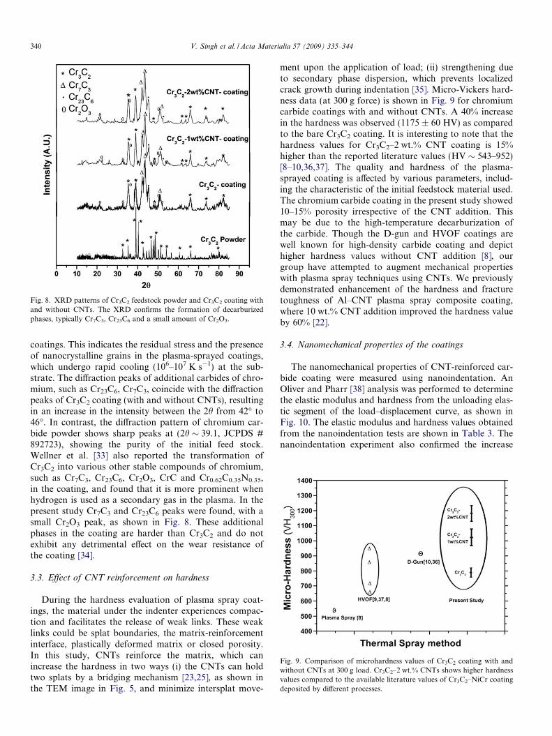
Fig. 8. XRD patterns of Cr3C2 feedstock powder and Cr3C2 coating withand without CNTs. The XRD confirms the formation of decarburizedphases, typically Cr7C3, Cr23C6 and a small amount of Cr2O3.
Fig. 9. Comparison of microhardness values of Cr3C2 coating with andwithout CNTs at 300 g load. Cr3C2–2 wt.% CNTs shows higher hardnessvalues compared to the available literature values of Cr3C2–NiCr coatingdeposited by different processes.
340 V. Singh et al. / Acta Materialia 57 (2009) 335–344
coatings. This indicates the residual stress and the presenceof nanocrystalline grains in the plasma-sprayed coatings,which undergo rapid cooling (106–107 K s�1) at the sub-strate. The diffraction peaks of additional carbides of chro-mium, such as Cr23C6, Cr7C3, coincide with the diffractionpeaks of Cr3C2 coating (with and without CNTs), resultingin an increase in the intensity between the 2h from 42� to46�. In contrast, the diffraction pattern of chromium car-bide powder shows sharp peaks at (2h � 39.1, JCPDS #892723), showing the purity of the initial feed stock.Wellner et al. [33] also reported the transformation ofCr3C2 into various other stable compounds of chromium,such as Cr7C3, Cr23C6, Cr2O3, CrC and Cr0.62C0.35N0.35,in the coating, and found that it is more prominent whenhydrogen is used as a secondary gas in the plasma. In thepresent study Cr7C3 and Cr23C6 peaks were found, with asmall Cr2O3 peak, as shown in Fig. 8. These additionalphases in the coating are harder than Cr3C2 and do notexhibit any detrimental effect on the wear resistance ofthe coating [34].
3.3. Effect of CNT reinforcement on hardness
During the hardness evaluation of plasma spray coat-ings, the material under the indenter experiences compac-tion and facilitates the release of weak links. These weaklinks could be splat boundaries, the matrix-reinforcementinterface, plastically deformed matrix or closed porosity.In this study, CNTs reinforce the matrix, which canincrease the hardness in two ways (i) the CNTs can holdtwo splats by a bridging mechanism [23,25], as shown inthe TEM image in Fig. 5, and minimize intersplat move-
ment upon the application of load; (ii) strengthening dueto secondary phase dispersion, which prevents localizedcrack growth during indentation [35]. Micro-Vickers hard-ness data (at 300 g force) is shown in Fig. 9 for chromiumcarbide coatings with and without CNTs. A 40% increasein the hardness was observed (1175 ± 60 HV) as comparedto the bare Cr3C2 coating. It is interesting to note that thehardness values for Cr3C2–2 wt.% CNT coating is 15%higher than the reported literature values (HV � 543–952)[8–10,36,37]. The quality and hardness of the plasma-sprayed coating is affected by various parameters, includ-ing the characteristic of the initial feedstock material used.The chromium carbide coating in the present study showed10–15% porosity irrespective of the CNT addition. Thismay be due to the high-temperature decarburization ofthe carbide. Though the D-gun and HVOF coatings arewell known for high-density carbide coating and depicthigher hardness values without CNT addition [8], ourgroup have attempted to augment mechanical propertieswith plasma spray techniques using CNTs. We previouslydemonstrated enhancement of the hardness and fracturetoughness of Al–CNT plasma spray composite coating,where 10 wt.% CNT addition improved the hardness valueby 60% [22].
3.4. Nanomechanical properties of the coatings
The nanomechanical properties of CNT-reinforced car-bide coating were measured using nanoindentation. AnOliver and Pharr [38] analysis was performed to determinethe elastic modulus and hardness from the unloading elas-tic segment of the load–displacement curve, as shown inFig. 10. The elastic modulus and hardness values obtainedfrom the nanoindentation tests are shown in Table 3. Thenanoindentation experiment also confirmed the increase
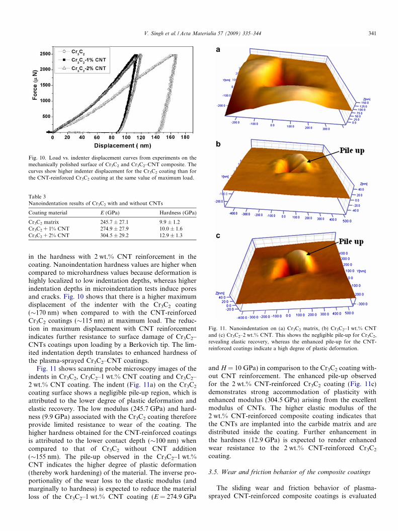
Fig. 10. Load vs. indenter displacement curves from experiments on themechanically polished surface of Cr3C2 and Cr3C2–CNT composite. Thecurves show higher indenter displacement for the Cr3C2 coating than forthe CNT-reinforced Cr3C2 coating at the same value of maximum load.
Table 3Nanoindentation results of Cr3C2 with and without CNTs
Coating material E (GPa) Hardness (GPa)
Cr3C2 matrix 245.7 ± 27.1 9.9 ± 1.2Cr3C2 + 1% CNT 274.9 ± 27.9 10.0 ± 1.6Cr3C2 + 2% CNT 304.5 ± 29.2 12.9 ± 1.3
Fig. 11. Nanoindentation on (a) Cr3C2 matrix, (b) Cr3C2–1 wt.% CNTand (c) Cr3C2–2 wt.% CNT. This shows the negligible pile-up for Cr3C2,revealing elastic recovery, whereas the enhanced pile-up for the CNT-reinforced coatings indicate a high degree of plastic deformation.
V. Singh et al. / Acta Materialia 57 (2009) 335–344 341
in the hardness with 2 wt.% CNT reinforcement in thecoating. Nanoindentation hardness values are higher whencompared to microhardness values because deformation ishighly localized to low indentation depths, whereas higherindentation depths in microindentation tests induce poresand cracks. Fig. 10 shows that there is a higher maximumdisplacement of the indenter with the Cr3C2 coating(�170 nm) when compared to with the CNT-reinforcedCr3C2 coatings (�115 nm) at maximum load. The reduc-tion in maximum displacement with CNT reinforcementindicates further resistance to surface damage of Cr3C2–CNTs coatings upon loading by a Berkovich tip. The lim-ited indentation depth translates to enhanced hardness ofthe plasma-sprayed Cr3C2–CNT coatings.
Fig. 11 shows scanning probe microscopy images of theindents in Cr3C2, Cr3C2–1 wt.% CNT coating and Cr3C2–2 wt.% CNT coating. The indent (Fig. 11a) on the Cr3C2
coating surface shows a negligible pile-up region, which isattributed to the lower degree of plastic deformation andelastic recovery. The low modulus (245.7 GPa) and hard-ness (9.9 GPa) associated with the Cr3C2 coating thereforeprovide limited resistance to wear of the coating. Thehigher hardness obtained for the CNT-reinforced coatingsis attributed to the lower contact depth (�100 nm) whencompared to that of Cr3C2 without CNT addition(�155 nm). The pile-up observed in the Cr3C2–1 wt.%CNT indicates the higher degree of plastic deformation(thereby work hardening) of the material. The inverse pro-portionality of the wear loss to the elastic modulus (andmarginally to hardness) is expected to reduce the materialloss of the Cr3C2–1 wt.% CNT coating (E = 274.9 GPa
and H = 10 GPa) in comparison to the Cr3C2 coating with-out CNT reinforcement. The enhanced pile-up observedfor the 2 wt.% CNT-reinforced Cr3C2 coating (Fig. 11c)demonstrates strong accommodation of plasticity withenhanced modulus (304.5 GPa) arising from the excellentmodulus of CNTs. The higher elastic modulus of the2 wt.% CNT-reinforced composite coating indicates thatthe CNTs are implanted into the carbide matrix and aredistributed inside the coating. Further enhancement inthe hardness (12.9 GPa) is expected to render enhancedwear resistance to the 2 wt.% CNT-reinforced Cr3C2
coating.
3.5. Wear and friction behavior of the composite coatings
The sliding wear and friction behavior of plasma-sprayed CNT-reinforced composite coatings is evaluated
342 V. Singh et al. / Acta Materialia 57 (2009) 335–344
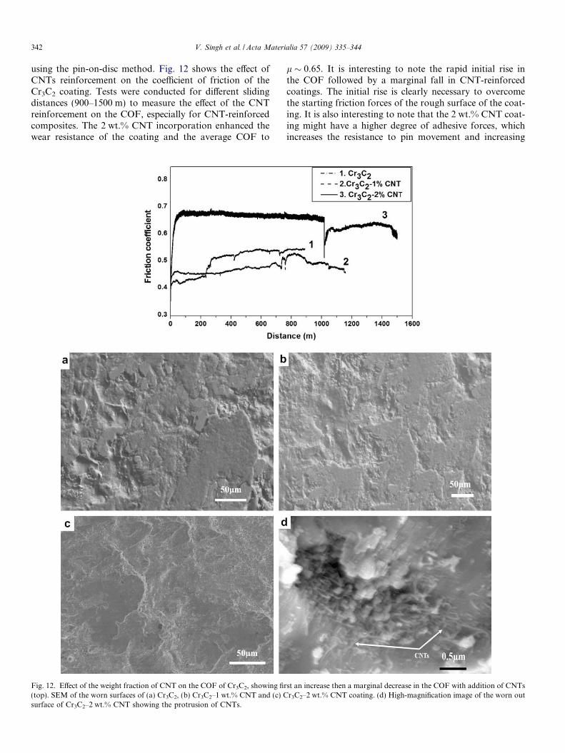
using the pin-on-disc method. Fig. 12 shows the effect ofCNTs reinforcement on the coefficient of friction of theCr3C2 coating. Tests were conducted for different slidingdistances (900–1500 m) to measure the effect of the CNTreinforcement on the COF, especially for CNT-reinforcedcomposites. The 2 wt.% CNT incorporation enhanced thewear resistance of the coating and the average COF to
Fig. 12. Effect of the weight fraction of CNT on the COF of Cr3C2, showing fir(top). SEM of the worn surfaces of (a) Cr3C2, (b) Cr3C2–1 wt.% CNT and (c) Csurface of Cr3C2–2 wt.% CNT showing the protrusion of CNTs.
l � 0.65. It is interesting to note the rapid initial rise inthe COF followed by a marginal fall in CNT-reinforcedcoatings. The initial rise is clearly necessary to overcomethe starting friction forces of the rough surface of the coat-ing. It is also interesting to note that the 2 wt.% CNT coat-ing might have a higher degree of adhesive forces, whichincreases the resistance to pin movement and increasing
st an increase then a marginal decrease in the COF with addition of CNTsr3C2–2 wt.% CNT coating. (d) High-magnification image of the worn out
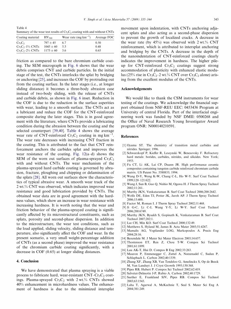
Table 4Summary of the wear test results of Cr3C2 coating with and without CNTs
Coating material HV300 Wear rate (mg km�1) Average FOC
Cr3C2 797 ± 45 6.7 0.50Cr3C2–1% CNTs 1045 ± 60 5.5 0.48Cr3C2–2% CNTs 1175 ± 60 3.6 0.65
V. Singh et al. / Acta Materialia 57 (2009) 335–344 343
friction as compared to the bare chromium carbide coat-ing. The SEM micrograph in Fig. 6 shows that the weardebris comprises CNT and carbide particles. In the initialstage of the test, the CNTs interlocks the splat by bridgingor anchoring [25], and increases the COF by protruding outfrom the coating surface. In the later stages (i.e., at longersliding distance) it becomes a three-body abrasion caseinstead of two-body sliding, with the release of CNTsand carbide debris, as shown in Fig. 6 inset. Reduction inthe COF is due to the reduction in the surface asperitieswith wear, leading to a smooth surface. The CNTs act asa lubricant and reduce the COF for the CNT-reinforcedcomposite during the later stages. This is in good agree-ment with the literature, where CNTs provide a lubricatingcondition during the abrasion between the coating and theselected counterpart [39,40]. Table 4 shows the averagewear rate of CNT-reinforced Cr3C2 coating in mg km�1.The wear rate decreases with increasing CNT fraction inthe coating. This is attributed to the fact that CNT rein-forcement anchors the carbides splat and improves thewear resistance of the coating. Fig. 12(a–d) shows theSEM of the worn out surfaces of plasma-sprayed Cr3C2
with and without CNTs. The wear mechanism of theplasma-sprayed hard carbide coating is governed by abra-sion, fracture, ploughing and chipping or delamination ofthe splats [28]. All worn out surfaces show the characteris-tics of typical abrasive wear. A smooth wear track of the2 wt.% CNT was observed, which indicates improved wearresistance and good lubrication provided by CNTs. Theobtained wear data are in good agreement with the hard-ness values, which show an increase in wear resistance withincreasing hardness. It is worth noting that the wear andfriction behavior of the plasma-sprayed coating is signifi-cantly affected by its microstructural constituents, such assplats, porosity and second-phase dispersion. In additionto the microstructure, the wear test conditions, such asthe load applied, sliding velocity, sliding distance and tem-perature, also significantly affect the COF and wear. In thepresent scenario, a very small weight-percentage additionof CNTs (as a second phase) improved the wear resistanceof the chromium carbide coating significantly, with adecrease in COF (0.65) at longer sliding distances.
4. Conclusion
We have demonstrated that plasma spraying is a viableprocess to fabricate hard, wear-resistant CNT–Cr3C2 coat-ings. Plasma-sprayed Cr3C2 with 2 wt.% CNTs showed40% enhancement in microhardness values. The enhance-ment of hardness is due to the minimized intersplat
movement upon indentation, with CNTs anchoring adja-cent splats and also acting as a second-phase dispersionto prevent the growth of localized cracks. A decrease inthe wear rate (by 45%) was observed with 2 wt.% CNTreinforcement, which is attributed to intersplat anchoringand bridging by the CNTs. A decrease in the depth ofthe nanoindentation of CNT-reinforced coatings clearlyindicates the improvement in hardness. The higher pile-up for CNT-reinforced Cr3C2 coatings suggest strongaccommodation of plasticity with enhanced elastic modu-lus (25% rise in Cr3C2–2 wt.% CNT over Cr3C2 alone) aris-ing from the excellent modulus of the CNTs.
Acknowledgements
We would like to thank the CSM instruments for weartesting of the coatings. We acknowledge the financial sup-port obtained from NSF-REU EEC: 0453436 Program atUniversity of central Florida. Part of the interfacial engi-neering work was funded by NSF DMII: 0500268 andthe Office of Naval Research Young Investigator Awardprogram ONR: N000140210591.
References
[1] Oyama ST. The chemistry of transition metal carbides andnitrides. Springer; 1996.
[2] Schwarzkopf P, Kieffer R, Leszynski W, Benesovsky F. Refractoryhard metals: borides, carbides, nitrides, and silicides. New York;1953.
[3] Fu CT, Li AK, Lai CP, Duann JR. High performance ceramiccomposites containing tungsten carbide reinforced chromium carbidematrix. US Patent No. 5580833; 1994.
[4] Wang D-Y, Weng K-W, Chang C-L, Ho W-Y. Surf Coat Technol1999;120–121:622.
[5] Wang J, Sun B, Guo Q, Nishio M, Ogawa H. J Therm Spray Technol2002;11:261.
[6] Murthy JKN, Venkataraman B. Surf Coat Technol 2006;200:2642.[7] Wolfe DE, Eden TJ, Potter JK, Jaroh AP. J Therm Spray Technol
2006;15:400.[8] Factor M, Roman I. J Therm Spray Technol 2002;11:468.[9] Ji G-C, Li C-J, Wang Y-Y, Li W-Y. Surf Coat Technol
2006;200:6749.[10] Murthy JKN, Bysakh S, Gopinath K, Venkataraman B. Surf Coat
Technol 2007;202:1.[11] Lee CH, Min KO. Surf Coat Technol 2000;132:49.[12] Matthews S, Hyland M, James B. Acta Mater 2003;51:4267.[13] Mamalis AG, Vogtlander LOG, Markopoulos A. Precis Eng
2004;28:16.[14] Baxendale M. J Mater Sci Mater Electron 2003;14:657.[15] Thostenson ET, Ren Z, Chou T-W. Compos Sci Technol
2001;61:1899.[16] Lau AK-T, Hui D. Compos B Eng 2002;33:263.[17] Mauron P, Emmenegger C, Zuttel A, Nutzenadel C, Sudan P,
Schlapbach L. Carbon 2002;40:1339.[18] Zhang XF, Zhang XB, Van Tendeloo G, Amelinckx S, Op de Beeck
M, Van Landuyt J. J Cryst Growth 1993;130:368.[19] Pipes RB, Hubert P. Compos Sci Technol 2002;62:419.[20] Salvetat-Delmotte J-P, Rubio A. Carbon 2002;40:1729.[21] Saether E, Frankland SJV, Pipes RB. Compos Sci Technol
2003;63:1543.[22] Laha T, Agarwal A, McKechnie T, Seal S. Mater Sci Eng A
2004;381:249.
344 V. Singh et al. / Acta Materialia 57 (2009) 335–344
[23] Balani K, Zhang T, Karakoti A, Li WZ, Seal S, Agarwal A. ActaMater 2008;56:571.
[24] Cha SI, Kim KT, Lee KH, Mo CB, Hong SH. Scripta Mater2005;53:793.
[25] Balani K, Anderson R, Laha T, Andara M, Tercero J, Crumpler E,et al. Biomaterials 2007;28:618.
[26] Xia Z, Riester L, Curtin WA, Li H, Sheldon BW, Liang J, et al. ActaMater 2004;52:931.
[27] Morsi K, Esawi A. J Mater Sci 2007;42:4954.[28] Factor M, Roman I. J Therm Spray Technol 2002;11:482.[29] Fan J-P, Zhuang D-M, Zhao D-Q, Gong Zhang, Wu M-S. Appl Phys
Lett 2006;89:121910.[30] Teng L, Lu K, Aune R, Seetharaman S. Metall Mater Trans A
2004;35:3649.
[31] Kleykamp H. J Alloys Compd 2001;321:138.[32] Li C-J, Ji G-C, Wang Y-Y, Sonoya K. Thin Solid Films 2002;419:137.[33] Wellner P, Erodos E, Marxer G. Sulzer research number 1978:59.[34] Vuoristo P, Niemi K, Makela A, Mantyla T. Proceedings of the 7th
national thermal spray conference, 20–24 June; 1994. p. 121.[35] Cha SI, Kim KT, Arshad SN, Mo CB, Hong SH. Adv Mater
1995;17:1377.[36] Mann BS, Prakash B. Wear 2000;240:223.[37] Sahraoui T, Fenineche N-E, Montavon G, Coddet C. Mater Des
2003;24:309.[38] Pharr GM, Oliver WC, Brotzen FR. J Mater Res 1992;7:613.[39] Li ZH, Wang XQ, Wang M, Wang FF, Ge HL. Tribo Int
2006;39:953.[40] Kim KT, Cha SI, Hong SH. Mater Sci Eng A 2007;449–451:46.