Embed Size (px)
Citation preview
Chronoscope RDM
Operating Manual
Document No. 11.4210D35e
Device: from Rel. 2.13 / Software: from Rel. 1.0.0
October 2014 Witschi Electronic Ltd. CH 3294 Büren a/Aare Switzerland Tel. +41 (0)32 - 352 05 00 Fax +41 (0)32 - 351 32 92 www.witschi.com [email protected]
General agent GermanyBirkenstock & Co. GmbH21500 Geesthacht Tel. +49 4152 809680 Fax +49 4152 809696 www.beco-technic.com

Witschi Electronic Ltd. - 2/31 - Chronoscope RDM
Witschi Electronic Ltd. - 3/31 - Chronoscope RDM
Table of contents
1 Description of symbols and notes .................................................................................................................... 4 1.1 Safety and information symbols .................................................................................................. 4
2 Safety regulations ........................................................................................................................................... 4
3 Disposal of the unit......................................................................................................................................... 5
4 General .......................................................................................................................................................... 5 4.1 Safety instructions .................................................................................................................... 5 4.2 Intended purpose ..................................................................................................................... 6
5 Scope of supply .............................................................................................................................................. 6
6 Commissioning the Réserve de Marche ........................................................................................................... 7 6.1 Removal of transportation safety restraint .................................................................................... 7 6.2 Connecting to power supply and switching on ............................................................................... 8
7 Operation ....................................................................................................................................................... 9 7.1 Inserting watches or watch movements ........................................................................................ 9 7.2 Adjusting the power reserve ..................................................................................................... 10 7.3 Activation/deactivation of unused/used channels ......................................................................... 10 7.4 Start measurement ................................................................................................................. 11 7.5 Interrupt measurement ........................................................................................................... 13
8 Maintenance ................................................................................................................................................ 14 8.1 Guarantee ............................................................................................................................ 14
9 Technical data .............................................................................................................................................. 15
10 EC Declaration of conformity ....................................................................................................................... 16
SOFTWARE ...................................................................................................................................................... 17
1 General concept ........................................................................................................................................... 17 1.1 Requirements ..................................................................................................................... 18 1.2 Special requirements ............................................................................................................ 18 1.3 Installation ........................................................................................................................ 18
2 Summary ................................................................................................................................................. 19 2.1 Summary of functions .......................................................................................................... 19
2.1.1 Screen ........................................................................................................................ 19 2.1.2 Menu bar .................................................................................................................... 20 2.1.3 Toolbar....................................................................................................................... 22 2.2 Using the device ............................................................................................................. 22 2.2.1 Start up the software program ........................................................................................ 22 2.2.2 Identification ............................................................................................................... 24 2.2.3 Results ....................................................................................................................... 25
3 Safety instructions ................................................................................................................................... 31
Witschi Electronic Ltd. - 4/31 - Chronoscope RDM
1 Description of symbols and notes
1.1 Safety and information symbols
Warning This symbol is used in these operating instructions to point out any possible risks.
Mandatory symbol Mandatory symbols are used to indicate a specific attitude when handling the Chronoscope RDM.
Tip Tips offer information on handling the test system and are optional, but they can make operation easier.
2 Safety regulations
Please read through all the information given in this Operating Manual very carefully. It gives you important instructions on the use, safety and maintenance of your unit. Store these instructions in a safe place and, if necessary, pass them on to subsequent users. The unit may only be used for its intended purpose according to this Operating Manual.
The manufacturer
Witschi Electronic Ltd., CH-3294 BÜREN a.A., SWITZERLAND
cannot accept liability for any damage caused by incorrect operation or usage!
Witschi Electronic Ltd. - 5/31 - Chronoscope RDM
3 Disposal of the unit
Recycling This electronic device must not be disposed of with normal household waste. If it is not accepted by a public collection depot, please give it back to the point of sale, which will deal with correct disposal according to statutory regulations. Your supplier in the EU will take back all devices manufactured after 13 August 2005 at no charge, as well as older units if a corresponding new device is purchased at the same time.
4 General
4.1 Safety instructions
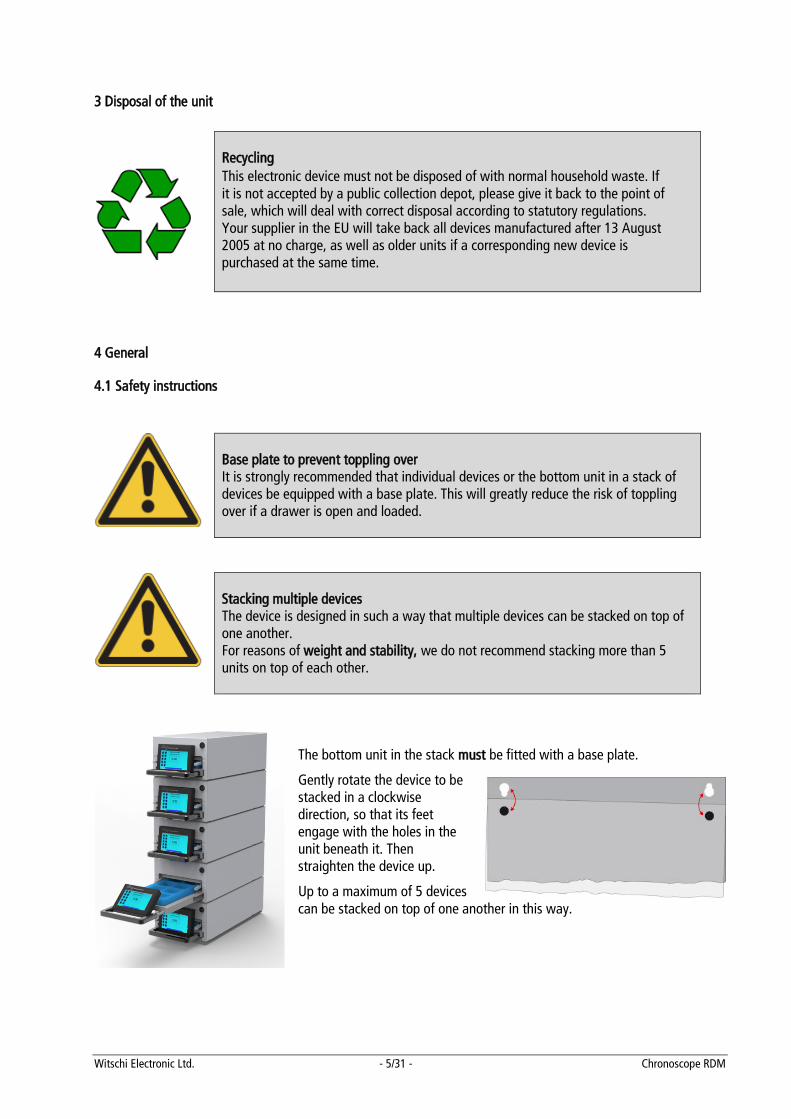
Base plate to prevent toppling over It is strongly recommended that individual devices or the bottom unit in a stack of devices be equipped with a base plate. This will greatly reduce the risk of toppling over if a drawer is open and loaded.
Stacking multiple devices The device is designed in such a way that multiple devices can be stacked on top of one another. For reasons of weight and stability, we do not recommend stacking more than 5 units on top of each other.
The bottom unit in the stack must be fitted with a base plate.
Gently rotate the device to be stacked in a clockwise direction, so that its feet engage with the holes in the unit beneath it. Then straighten the device up.
Up to a maximum of 5 devices can be stacked on top of one another in this way.
Witschi Electronic Ltd. - 6/31 - Chronoscope RDM
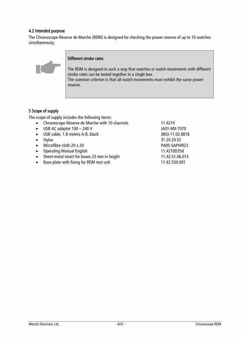
4.2 Intended purpose The Chronoscope Réserve de Marche (RDM) is designed for checking the power reserve of up to 10 watches simultaneously.
Different stroke rates The RDM is designed in such a way that watches or watch movements with different stroke rates can be tested together in a single box. The common criterion is that all watch movements must exhibit the same power reserve.
5 Scope of supply The scope of supply includes the following items:
• Chronoscope Réserve de Marche with 10 channels 11.4210 • USB AC adaptor 100 – 240 V JA01-MX-T070 • USB cable, 1.8 metres A-B, black JB03-11.02.8818 • Stylus 31.20.20.52 • Microfibre cloth 20 x 20 PA05-SAPHIR23 • Operating Manual English 11.4210D35d • Sheet-metal insert for boxes 23 mm in height 11.42.51.06.015 • Base plate with fixing for RDM test unit 11.42.530.001

Witschi Electronic Ltd. - 7/31 - Chronoscope RDM
6 Commissioning the Réserve de Marche
6.1 Removal of transportation safety restraint In order to prevent damage to the mechanism, the Réserve de Marche is shipped with a transportation safety restraint. This consists of a screw which protects the mechanism inside the device from damage. The transportation safety restraint is located on the bottom left-hand side of the unit.
To remove the transportation safety restraint please do not turn the device over, but gently lift it. The transportation safety restraint screw can be stored in the opening provided for the purpose.
Once the transportation safety restraint has been removed, the microphone unit can be raised by applying gentle pressure to both opening levers – and the drawer pulled out. The foam insert also provides protection during transportation and should be stored together with the securing screw.
Witschi Electronic Ltd. - 8/31 - Chronoscope RDM
6.2 Connecting to power supply and switching on The Chronoscope Réserve de Marche is connected to the power supply using the USB mains adaptor and USB cable supplied.
Warning Given its increased power requirements, we do not recommend plugging the Réserve de Marche directly into the USB port of a PC, but always operating it with the mains adaptor supplied or a powered hub.
Tip The USB mains adaptor has a wide voltage input range and can be connected to all standard mains power supplies with voltages in the range from 100 to 240 V AC, 50 to 60 Hz.
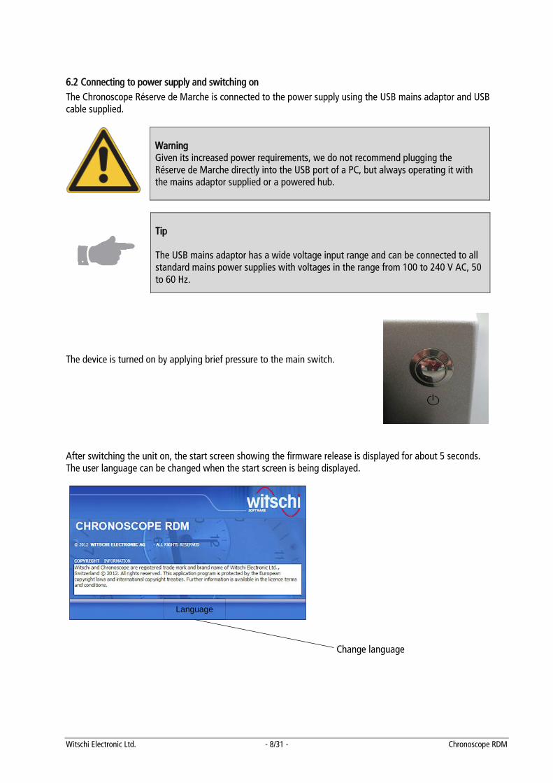
The device is turned on by applying brief pressure to the main switch. After switching the unit on, the start screen showing the firmware release is displayed for about 5 seconds. The user language can be changed when the start screen is being displayed.
Change language
Language
Witschi Electronic Ltd. - 9/31 - Chronoscope RDM
7 Operation
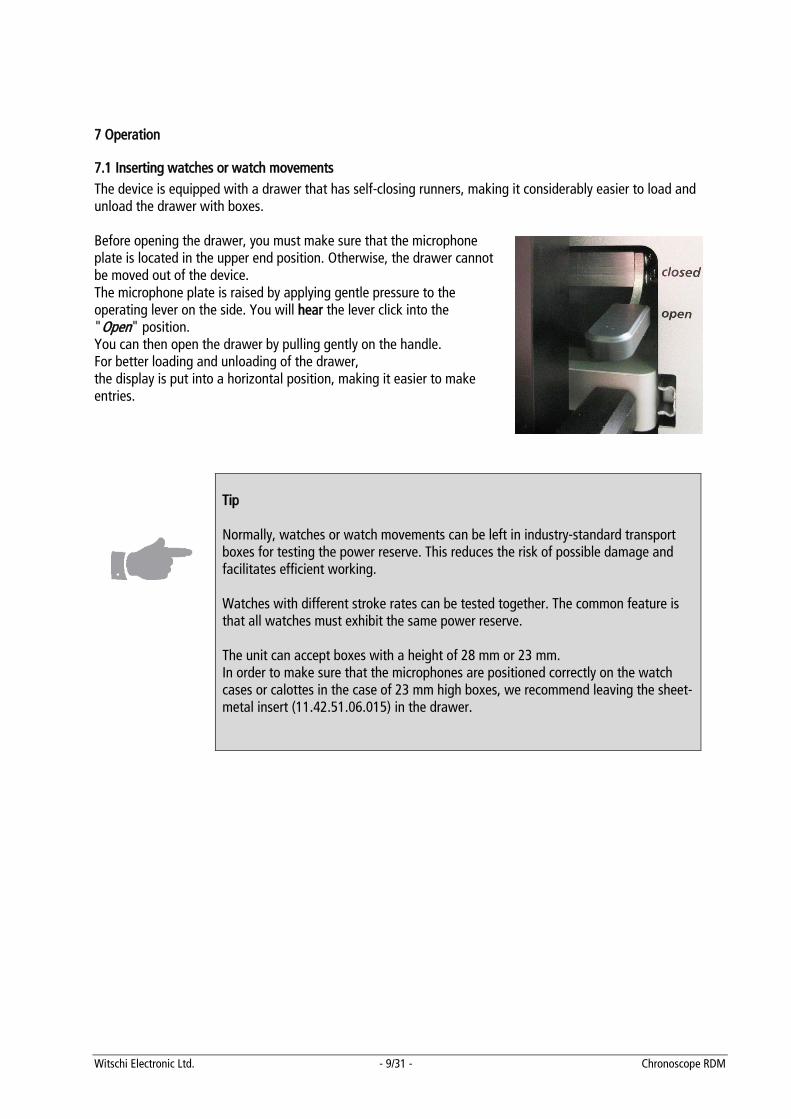
7.1 Inserting watches or watch movements The device is equipped with a drawer that has self-closing runners, making it considerably easier to load and unload the drawer with boxes. Before opening the drawer, you must make sure that the microphone plate is located in the upper end position. Otherwise, the drawer cannot be moved out of the device. The microphone plate is raised by applying gentle pressure to the operating lever on the side. You will hear the lever click into the "Open" position. You can then open the drawer by pulling gently on the handle. For better loading and unloading of the drawer, the display is put into a horizontal position, making it easier to make entries.
Tip Normally, watches or watch movements can be left in industry-standard transport boxes for testing the power reserve. This reduces the risk of possible damage and facilitates efficient working. Watches with different stroke rates can be tested together. The common feature is that all watches must exhibit the same power reserve. The unit can accept boxes with a height of 28 mm or 23 mm. In order to make sure that the microphones are positioned correctly on the watch cases or calottes in the case of 23 mm high boxes, we recommend leaving the sheet-metal insert (11.42.51.06.015) in the drawer.
Witschi Electronic Ltd. - 10/31 - Chronoscope RDM
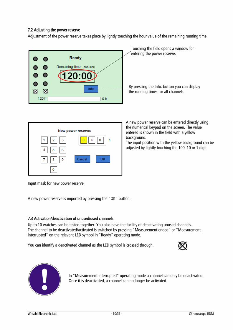
7.2 Adjusting the power reserve Adjustment of the power reserve takes place by lightly touching the hour value of the remaining running time.
A new power reserve can be entered directly using the numerical keypad on the screen. The value entered is shown in the field with a yellow background. The input position with the yellow background can be adjusted by lightly touching the 100, 10 or 1 digit.
Input mask for new power reserve A new power reserve is imported by pressing the "OK" button.
7.3 Activation/deactivation of unused/used channels Up to 10 watches can be tested together. You also have the facility of deactivating unused channels. The channel to be deactivated/activated is switched by pressing "Measurement ended" or "Measurement interrupted" on the relevant LED symbol in "Ready" operating mode. You can identify a deactivated channel as the LED symbol is crossed through.
In "Measurement interrupted" operating mode a channel can only be deactivated. Once it is deactivated, a channel can no longer be activated.
Touching the field opens a window for entering the power reserve.
By pressing the Info. button you can display the running times for all channels.
Witschi Electronic Ltd. - 11/31 - Chronoscope RDM
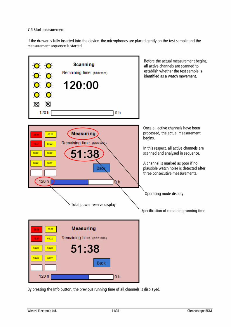
7.4 Start measurement If the drawer is fully inserted into the device, the microphones are placed gently on the test sample and the measurement sequence is started.
Before the actual measurement begins, all active channels are scanned to establish whether the test sample is identified as a watch movement.
Once all active channels have been processed, the actual measurement begins. In this respect, all active channels are scanned and analysed in sequence. A channel is marked as poor if no plausible watch noise is detected after three consecutive measurements.
By pressing the Info button, the previous running time of all channels is displayed.
Operating mode display
Specification of remaining running time Total power reserve display
Witschi Electronic Ltd. - 12/31 - Chronoscope RDM
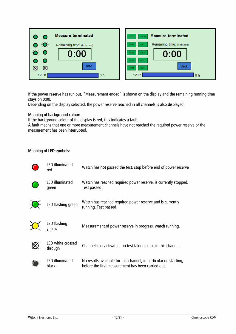
If the power reserve has run out, "Measurement ended" is shown on the display and the remaining running time stays on 0:00. Depending on the display selected, the power reserve reached in all channels is also displayed. Meaning of background colour: If the background colour of the display is red, this indicates a fault. A fault means that one or more measurement channels have not reached the required power reserve or the measurement has been interrupted. Meaning of LED symbols:
LED illuminated red Watch has not passed the test, stop before end of power reserve
LED illuminated green
Watch has reached required power reserve, is currently stopped. Test passed!
LED flashing green Watch has reached required power reserve and is currently running. Test passed!
LED flashing yellow Measurement of power reserve in progress, watch running.
LED white crossed through Channel is deactivated, no test taking place in this channel.
LED illuminated black
No results available for this channel, in particular on starting, before the first measurement has been carried out.
Witschi Electronic Ltd. - 13/31 - Chronoscope RDM
7.5 Interrupt measurement A current measurement can be interrupted. For example, this can be necessary if it is established that individual watches are not working correctly and they must be removed from the device before starting the power reserve measurement.
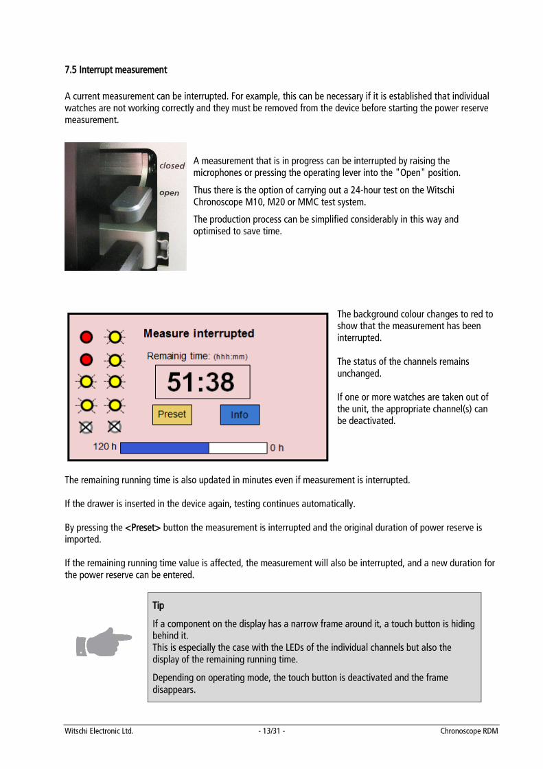
A measurement that is in progress can be interrupted by raising the microphones or pressing the operating lever into the "Open" position.
Thus there is the option of carrying out a 24-hour test on the Witschi Chronoscope M10, M20 or MMC test system.
The production process can be simplified considerably in this way and optimised to save time.
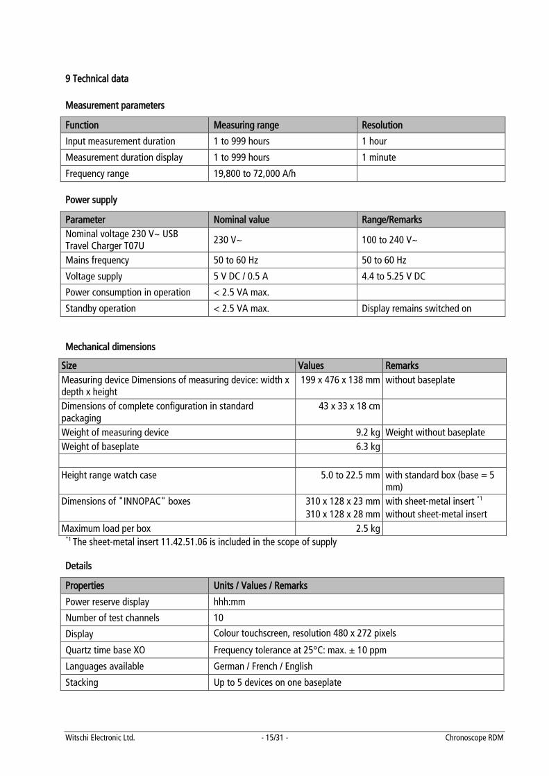
The background colour changes to red to show that the measurement has been interrupted. The status of the channels remains unchanged. If one or more watches are taken out of the unit, the appropriate channel(s) can be deactivated.
The remaining running time is also updated in minutes even if measurement is interrupted. If the drawer is inserted in the device again, testing continues automatically. By pressing the <Preset> button the measurement is interrupted and the original duration of power reserve is imported. If the remaining running time value is affected, the measurement will also be interrupted, and a new duration for the power reserve can be entered.
Tip
If a component on the display has a narrow frame around it, a touch button is hiding behind it. This is especially the case with the LEDs of the individual channels but also the display of the remaining running time.
Depending on operating mode, the touch button is deactivated and the frame disappears.

Witschi Electronic Ltd. - 14/31 - Chronoscope RDM
8 Maintenance This device requires no special maintenance. If necessary, the display can be cleaned with a soft cloth. Never use aggressive cleaning agents or solvents. The drawer runners can also be cleaned with a paper napkin from time to time. For technical support please contact our Customer Service.
This device does not need to be calibrated!
Shipping the device If you have to ship the unit anywhere, a foam insert must be placed without fail on the drawer and drawer retracted. Also the transportation safety restraint must be applied to prevent any damage to the mechanism. In this respect, please see the chapter entitled "Remove the transportation safety restraint".
8.1 Guarantee
Witschi Electronic Ltd. guarantees its device for 2 years from the purchase date. We promise to replace free-of-charge any parts of the device that become defective as a result of material or manufacturing faults within the guarantee period. Returns must be made in the original packaging. Transport costs will be for the account of the purchaser.
Witschi Electronic Ltd. - 15/31 - Chronoscope RDM
9 Technical data Measurement parameters
Function Measuring range Resolution
Input measurement duration 1 to 999 hours 1 hour
Measurement duration display 1 to 999 hours 1 minute
Frequency range 19,800 to 72,000 A/h Power supply
Parameter Nominal value Range/Remarks Nominal voltage 230 V~ USB Travel Charger T07U 230 V~ 100 to 240 V~
Mains frequency 50 to 60 Hz 50 to 60 Hz
Voltage supply 5 V DC / 0.5 A 4.4 to 5.25 V DC
Power consumption in operation < 2.5 VA max.
Standby operation < 2.5 VA max. Display remains switched on Mechanical dimensions
Size Values Remarks Measuring device Dimensions of measuring device: width x depth x height
199 x 476 x 138 mm without baseplate
Dimensions of complete configuration in standard packaging
43 x 33 x 18 cm
Weight of measuring device 9.2 kg Weight without baseplate Weight of baseplate 6.3 kg Height range watch case 5.0 to 22.5 mm with standard box (base = 5
mm) Dimensions of "INNOPAC" boxes 310 x 128 x 23 mm
310 x 128 x 28 mm with sheet-metal insert *1 without sheet-metal insert
Maximum load per box 2.5 kg *1 The sheet-metal insert 11.42.51.06 is included in the scope of supply Details
Properties Units / Values / Remarks
Power reserve display hhh:mm
Number of test channels 10
Display Colour touchscreen, resolution 480 x 272 pixels
Quartz time base XO Frequency tolerance at 25°C: max. ± 10 ppm
Languages available German / French / English
Stacking Up to 5 devices on one baseplate
Witschi Electronic Ltd. - 16/31 - Chronoscope RDM
10 EC Declaration of conformity The device conforms with the following provisions of EC directives: Guidelines:
2004/108/EC Electromagnetic compatibility 2006/42/EC EC machinery directive
Standards: EN 61326-1:2006 Electrical equipment for measurement, control and laboratory use.
EMC requirements, general requirements. EN ISO 12100-x Safety of machinery EN 550022:2006 Information technology equipment. Radio disturbance characteristics.
Limits and methods of measurement. IEC 1000-4-x Electromagnetic compatibility (EMC), HF, Burst, Surge, Cond. Immunity, 50 Hz
Magn. Pulse, Dips
Witschi Electronic Ltd. - 17/31 - Chronoscope RDM
SOFTWARE
1 General concept The Chronoscope RDM software enables the easy monitoring of several RDM devices. Ideally, if multiple devices (up to 20) are connected. The status of individual devices can be printed out or exported as a .csv file at any time. Facts and arguments about PC software: Displaying up to 20 connected RDMs. You can therefore currently review up to 200 watches (10 per box),
later up to 400 watches (20 per box). Review the status of all devices (previous time/remaining running time/faults) or of one device whilst
complying with the required security stipulations (watches remain in the safe during the test) Testing accurate to the minute of the required power reserve, irrespective of whether power reserve ends
at night, during the week or over the weekend. Adjustable automatic function to print out results after measurement duration elapsed
Simple, easy-to-interpret display of results
Free configuration of connected devices
The configuration of the devices connected can be displayed in the PC software - conditional. The arrangement of the box positions can be adapted individually to suit your own requirements.
Individual labelling of each measurement channel or via common designation of box to be tested.
Inputs can be made using a keypad or with the aid of a barcode scanner Option of placing a print-out in a suitable format (A5/A4) in a tested box
Software can also be operated via the touch screen
Display of power reserve achieved - even if above required power reserve
Easy software installation thanks to installation program
Minimal expenditure on cables, 4 devices brought together with a USB hub (powered) and possibly
connected to a PC via a further hub. Multilingual, intuitive user interface (d / f / e)
Operating systems supported: Windows 7.0, 8.0
Witschi Electronic Ltd. - 18/31 - Chronoscope RDM
1.1 Requirements
The requirements of the PC are:
• Operating system: Windows 7 (32 or 64 bit)
• RAM: min. 2 GB.
• USB port
• Screen resolution of min. 1024 x 768 pixels, colour: 32 bit.
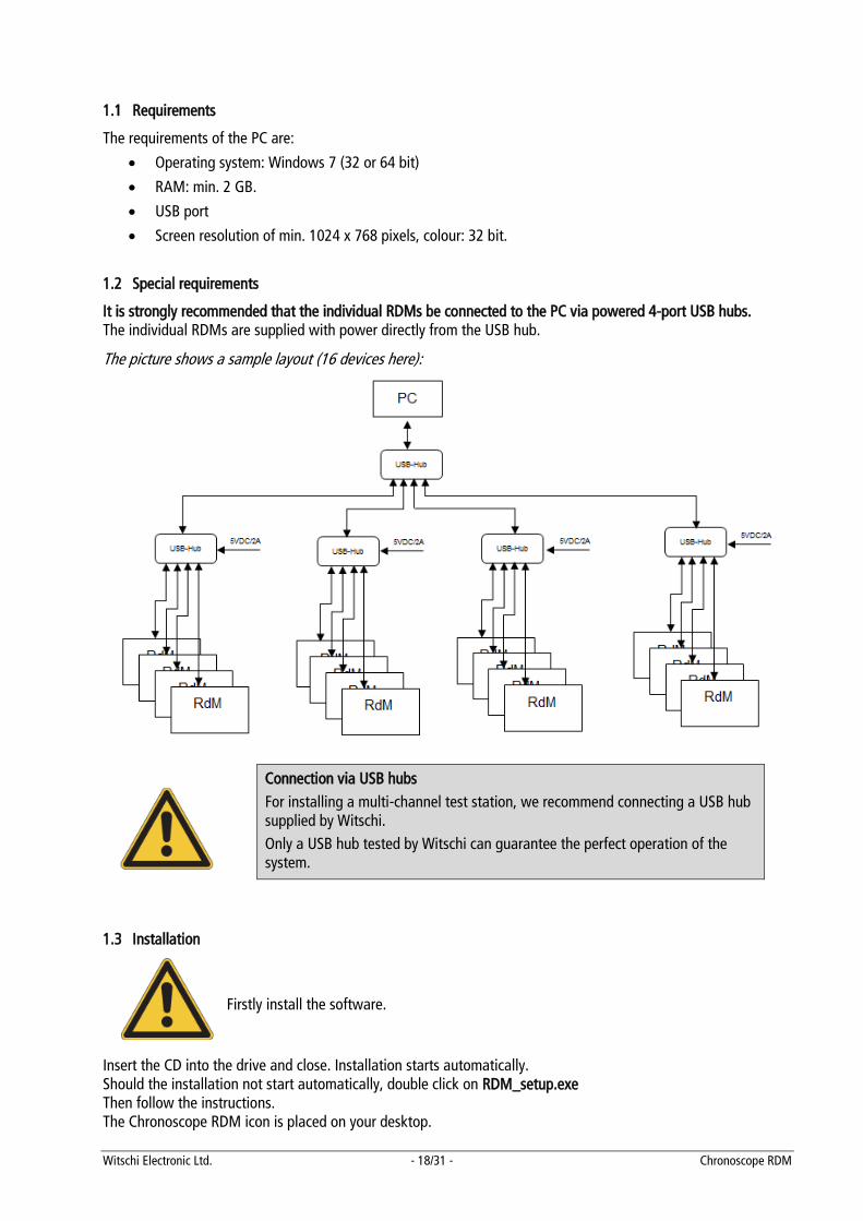
1.2 Special requirements
It is strongly recommended that the individual RDMs be connected to the PC via powered 4-port USB hubs. The individual RDMs are supplied with power directly from the USB hub.
The picture shows a sample layout (16 devices here):
Connection via USB hubs For installing a multi-channel test station, we recommend connecting a USB hub supplied by Witschi. Only a USB hub tested by Witschi can guarantee the perfect operation of the system.
1.3 Installation
Firstly install the software.
Insert the CD into the drive and close. Installation starts automatically. Should the installation not start automatically, double click on RDM_setup.exe Then follow the instructions. The Chronoscope RDM icon is placed on your desktop.
Witschi Electronic Ltd. - 19/31 - Chronoscope RDM
2 Summary
The following instructions will help you operate the test system quickly and easily. Users can quickly familiarise themselves with the system with simple commands and entries.
2.1 Summary of functions
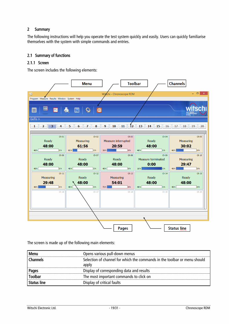
2.1.1 Screen
The screen includes the following elements:
The screen is made up of the following main elements:
Menu Opens various pull-down menus Channels Selection of channel for which the commands in the toolbar or menu should
apply Pages Display of corresponding data and results Toolbar The most important commands to click on Status line Display of critical faults
Witschi Electronic Ltd. - 20/31 - Chronoscope RDM
2.1.2 Menu bar
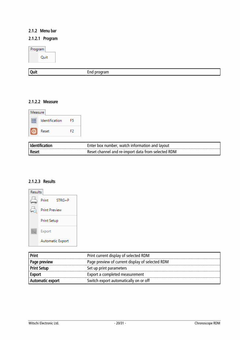
2.1.2.1 Program
Quit End program
2.1.2.2 Measure
Identification Enter box number, watch information and layout Reset Reset channel and re-import data from selected RDM
2.1.2.3 Results
Print Print current display of selected RDM Page preview Page preview of current display of selected RDM Print Setup Set up print parameters Export Export a completed measurement Automatic export Switch export automatically on or off
Witschi Electronic Ltd. - 21/31 - Chronoscope RDM
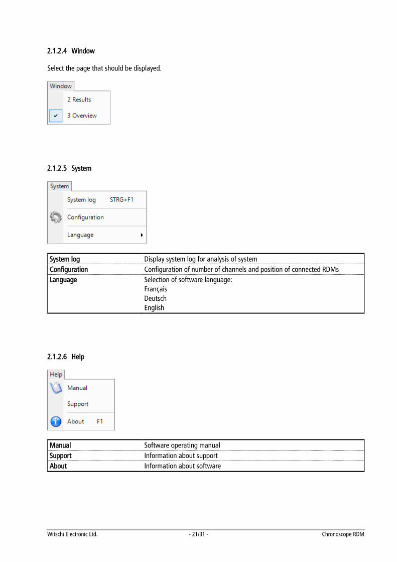
2.1.2.4 Window Select the page that should be displayed.
2.1.2.5 System
System log Display system log for analysis of system Configuration Configuration of number of channels and position of connected RDMs Language Selection of software language:
Français Deutsch English
2.1.2.6 Help
Manual Software operating manual Support Information about support About Information about software
Witschi Electronic Ltd. - 22/31 - Chronoscope RDM
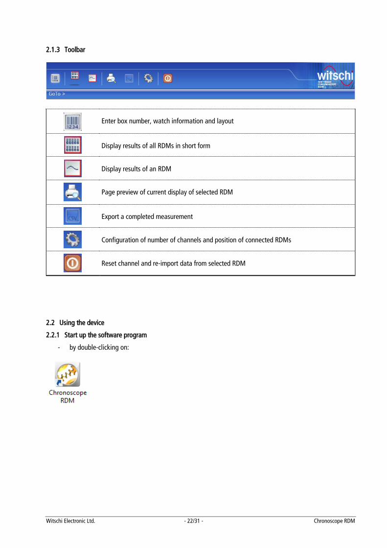
2.1.3 Toolbar
Enter box number, watch information and layout
Display results of all RDMs in short form
Display results of an RDM
Page preview of current display of selected RDM
Export a completed measurement
Configuration of number of channels and position of connected RDMs
Reset channel and re-import data from selected RDM
2.2 Using the device
2.2.1 Start up the software program
- by double-clicking on:
Witschi Electronic Ltd. - 23/31 - Chronoscope RDM
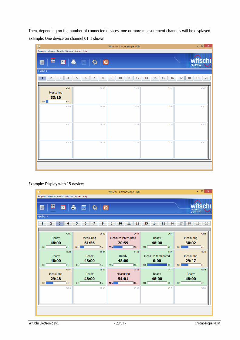
Then, depending on the number of connected devices, one or more measurement channels will be displayed.
Example: One device on channel 01 is shown
Example: Display with 15 devices
Witschi Electronic Ltd. - 24/31 - Chronoscope RDM
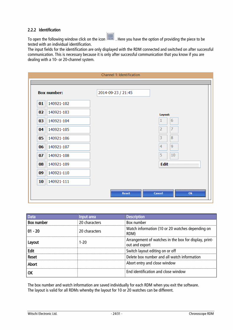
2.2.2 Identification
To open the following window click on the icon . Here you have the option of providing the piece to be tested with an individual identification. The input fields for the identification are only displayed with the RDM connected and switched on after successful communication. This is necessary because it is only after successful communication that you know if you are dealing with a 10- or 20-channel system.
Data Input area Description Box number 20 characters Box number
01 - 20 20 characters Watch information (10 or 20 watches depending on RDM)
Layout 1-20 Arrangement of watches in the box for display, print-out and export
Edit Switch layout editing on or off Reset Delete box number and all watch information
Abort Abort entry and close window
OK End identification and close window
The box number and watch information are saved individually for each RDM when you exit the software. The layout is valid for all RDMs whereby the layout for 10 or 20 watches can be different.
Witschi Electronic Ltd. - 25/31 - Chronoscope RDM
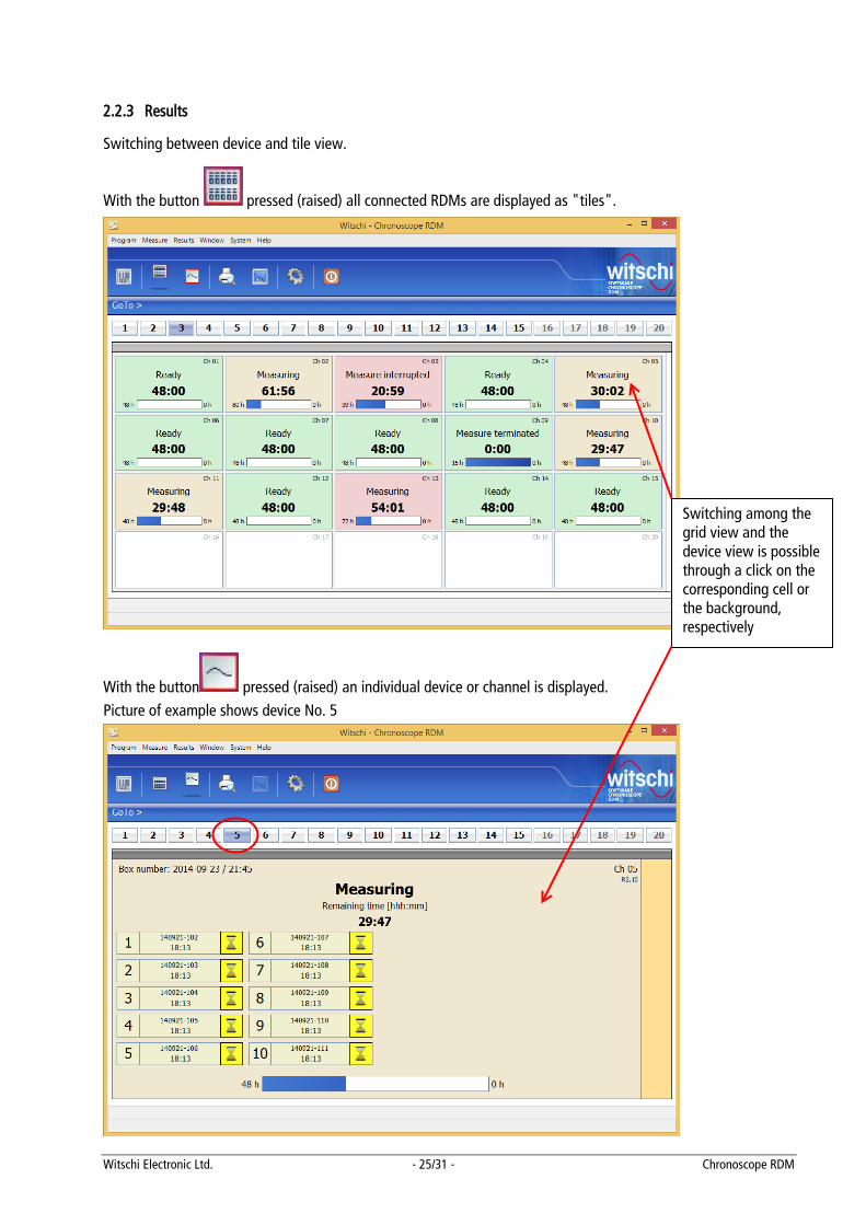
2.2.3 Results
Switching between device and tile view.
With the button pressed (raised) all connected RDMs are displayed as "tiles".
With the button pressed (raised) an individual device or channel is displayed. Picture of example shows device No. 5
Switching among the grid view and the device view is possible through a click on the corresponding cell or the background, respectively
Witschi Electronic Ltd. - 26/31 - Chronoscope RDM
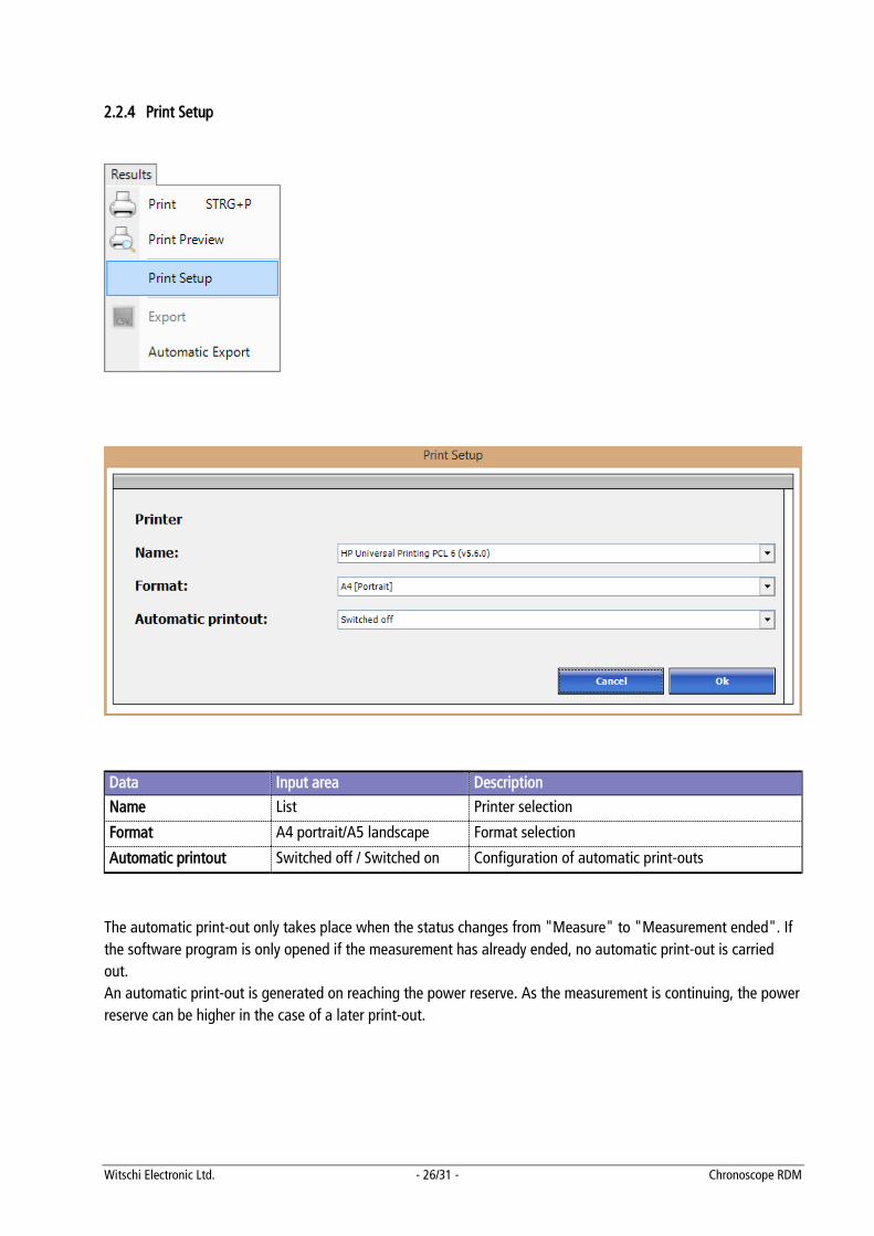
2.2.4 Print Setup
Data Input area Description
Name List Printer selection
Format A4 portrait/A5 landscape Format selection
Automatic printout Switched off / Switched on Configuration of automatic print-outs
The automatic print-out only takes place when the status changes from "Measure" to "Measurement ended". If the software program is only opened if the measurement has already ended, no automatic print-out is carried out. An automatic print-out is generated on reaching the power reserve. As the measurement is continuing, the power reserve can be higher in the case of a later print-out.
Witschi Electronic Ltd. - 27/31 - Chronoscope RDM
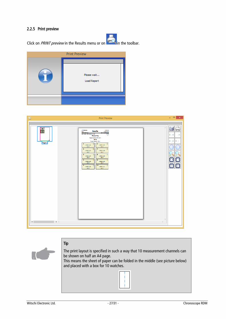
2.2.5 Print preview
Click on PRINT preview in the Results menu or on in the toolbar.
Tip
The print layout is specified in such a way that 10 measurement channels can be shown on half an A4 page. This means the sheet of paper can be folded in the middle (see picture below) and placed with a box for 10 watches.
Witschi Electronic Ltd. - 28/31 - Chronoscope RDM
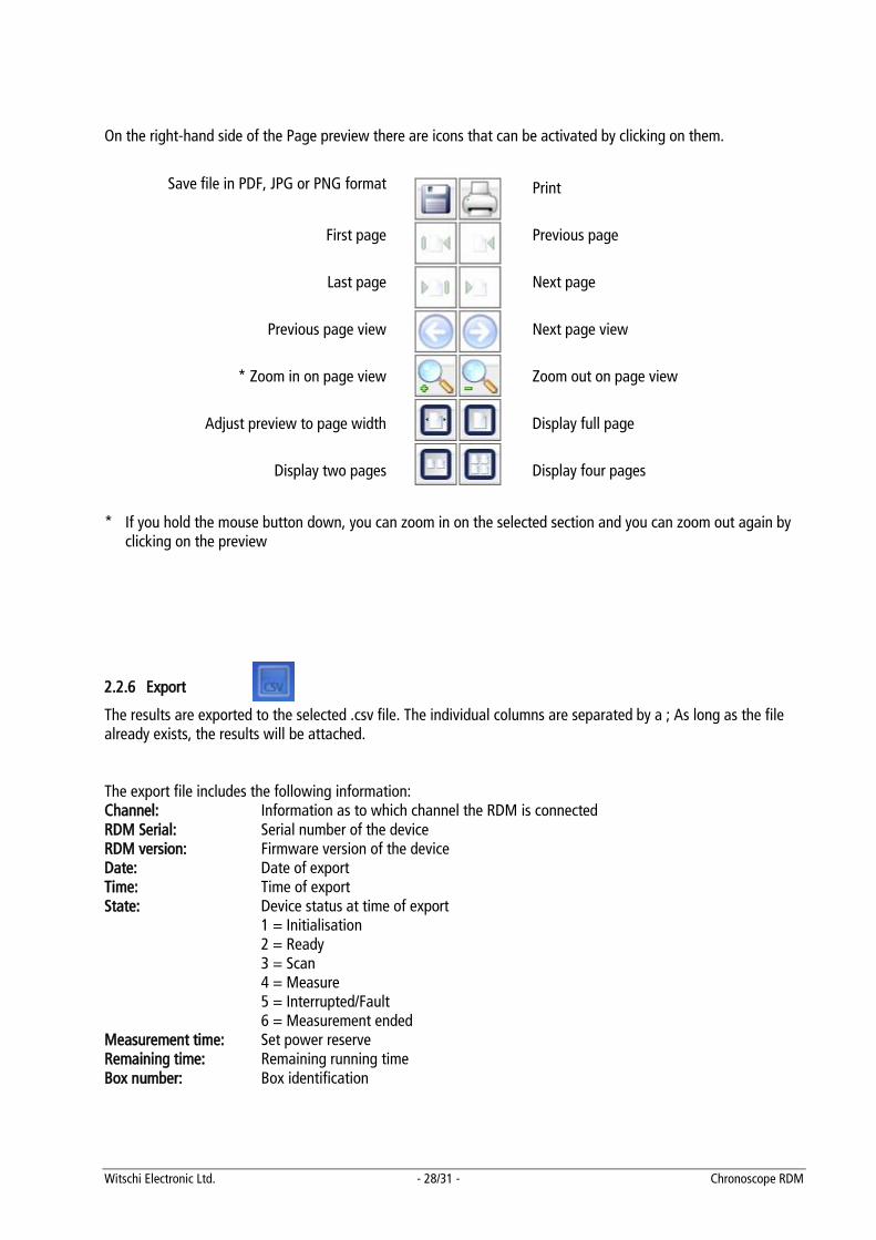
On the right-hand side of the Page preview there are icons that can be activated by clicking on them.
Save file in PDF, JPG or PNG format Print
First page Previous page
Last page Next page
Previous page view Next page view
* Zoom in on page view Zoom out on page view
Adjust preview to page width Display full page
Display two pages Display four pages
* If you hold the mouse button down, you can zoom in on the selected section and you can zoom out again by
clicking on the preview
2.2.6 Export
The results are exported to the selected .csv file. The individual columns are separated by a ; As long as the file already exists, the results will be attached. The export file includes the following information: Channel: Information as to which channel the RDM is connected RDM Serial: Serial number of the device RDM version: Firmware version of the device Date: Date of export Time: Time of export State: Device status at time of export
1 = Initialisation 2 = Ready 3 = Scan 4 = Measure 5 = Interrupted/Fault 6 = Measurement ended
Measurement time: Set power reserve Remaining time: Remaining running time Box number: Box identification
Witschi Electronic Ltd. - 29/31 - Chronoscope RDM
The following information is output for each watch: Watch number: Number of watch movement or watch in the box Watch State: Status of watch at time of export
0 = No result 1 = Deactivated 2 = Measure (flashing yellow) 3 = OK_1 (flashing green) watch has passed test and is running 4 = OK_2 (illuminated green) watch has passed test and is at a standstill 6 = KO_2 (illuminated red) watch has not passed test
Watch information: Additional information (serial number, etc.) Watch time: Running time watch has reached or at time of export
2.2.7 Export automatically
Automatic export only takes place when the status changes from "Measure" to "Measurement ended". The data is exported to the file 'export.csv'. As long as the file already exists, the results will be attached. The file is located in the folder 'Public documents' in the directory 'Chronoscope_RDM'. The path and name of the file can be changed in the configuration file.
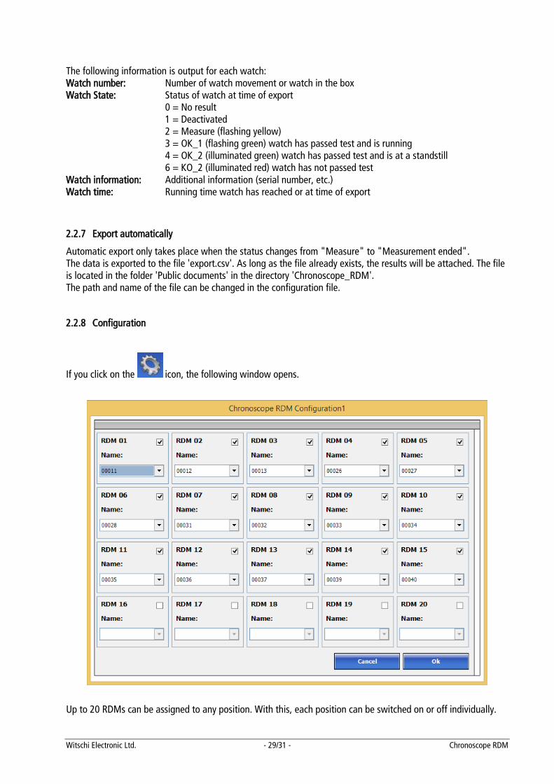
2.2.8 Configuration
If you click on the icon, the following window opens.
Up to 20 RDMs can be assigned to any position. With this, each position can be switched on or off individually.
Witschi Electronic Ltd. - 30/31 - Chronoscope RDM
The configuration file 'Chronoscope_RDM.ini' can be found in the folder 'Public documents' in the 'Chronoscope_RDM' directory. This is automatically applied the first time you exit the software. CAUTION: This is normally intended for the SAV and not for customers! Exception: path and file name for automatic export. Application AutoExport 0 = Switched off
1 = Switched on AutoPrint 0 = Switched off
1 = Switched on ExportFile Path and file name for automatic export. The
path must exist! Language Current language (de, fr, en) Printer Name of selected printer PrintFormat 0 = A4 portrait
1 = A5 landscape RDM 01-20 False = Switched off
True = Switched on RDM 01-20 BoxNumber Box number RDM 01-20 SerialNumber Serial number of RDM RDM 01-20 Information Watch information RDM Numbers 10 Layout for 10 watches RDM Numbers 20 Layout for 20 watches
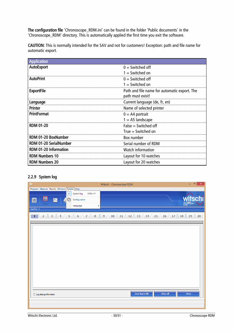
2.2.9 System log
Witschi Electronic Ltd. - 31/31 - Chronoscope RDM
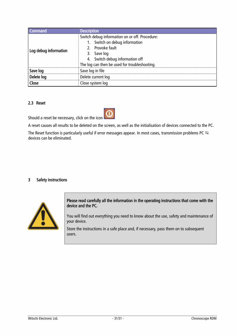
Command Description
Log debug information
Switch debug information on or off. Procedure: 1. Switch on debug information 2. Provoke fault 3. Save log 4. Switch debug information off
The log can then be used for troubleshooting. Save log Save log in file Delete log Delete current log Close Close system log
2.3 Reset
Should a reset be necessary, click on the icon
A reset causes all results to be deleted on the screen, as well as the initialisation of devices connected to the PC.
The Reset function is particularly useful if error messages appear. In most cases, transmission problems PC devices can be eliminated.
3 Safety instructions
Please read carefully all the information in the operating instructions that come with the device and the PC. You will find out everything you need to know about the use, safety and maintenance of your device.
Store the instructions in a safe place and, if necessary, pass them on to subsequent users.


![RDM [module] RDM-[module]-1… · medium rdm-[module]-15 aheeehapkfgloppjljhoekmmlaanogfkbpaheeeha bnfffnbpepadepelacadbhecbkjpbhfgnpbnfffnb jaibeeflfohfjhjkaphgbjahblpaggncggelagnep](https://img.pdfslide.net/doc/110x75/5fa322a37cebb95cfe55ebc7/rdm-module-rdm-module-1-medium-rdm-module-15-aheeehapkfgloppjljhoekmmlaanogfkbpaheeeha.jpg)
![IMP - MML IMP - MML IMP - MML IMP - IPDU[SA-5] CVCZ [EA-3] [EA-5] ZRP E1 RDM ZRP RDM CZ OU I1 VT E1 RDM PTP PTP E1 ZRP RDM E1 RDM PTP PTP E1 CZ RDM CV RDM RDM E1 E1 CV CZ RDM CV …](https://img.pdfslide.net/doc/110x75/613f5e17a7a58608c268e102/imp-mml-imp-mml-imp-mml-imp-sa-5-cvcz-ea-3-ea-5-zrp-e1-rdm-zrp-rdm.jpg)