Embed Size (px)
Citation preview
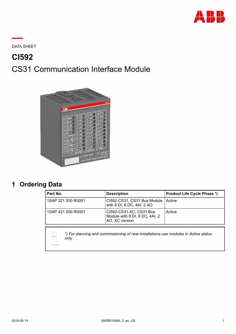
DATA SHEET
CI592CS31 Communication Interface Module
1 Ordering DataPart No. Description Product Life Cycle Phase *)
1SAP 221 200 R0001 CI592-CS31, CS31 Bus Modulewith 8 DI, 8 DC, 4AI, 2 AO
Active
1SAP 421 200 R0001 CI592-CS31-XC, CS31 BusModule with 8 DI, 8 DC, 4AI, 2AO, XC version
Active
*) For planning and commissioning of new installations use modules in Active statusonly.
Ordering Data
2018-05-14 3ADR010005, 2, en_US 1
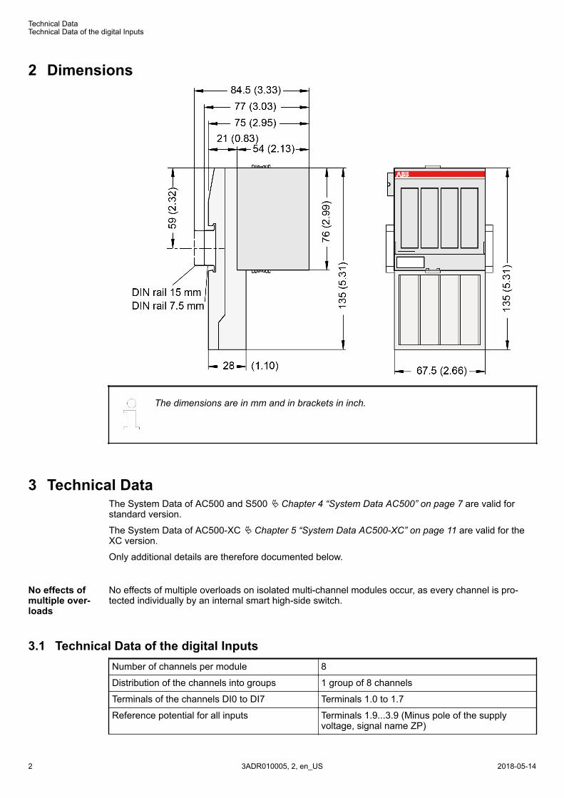
2 Dimensions
The dimensions are in mm and in brackets in inch.
3 Technical DataThe System Data of AC500 and S500 Ä Chapter 4 “System Data AC500” on page 7 are valid forstandard version.
The System Data of AC500-XC Ä Chapter 5 “System Data AC500-XC” on page 11 are valid for theXC version.
Only additional details are therefore documented below.
No effects of multiple overloads on isolated multi-channel modules occur, as every channel is pro-tected individually by an internal smart high-side switch.
3.1 Technical Data of the digital InputsNumber of channels per module 8
Distribution of the channels into groups 1 group of 8 channels
Terminals of the channels DI0 to DI7 Terminals 1.0 to 1.7
Reference potential for all inputs Terminals 1.9...3.9 (Minus pole of the supplyvoltage, signal name ZP)
No effects ofmultiple over-loads
Technical DataTechnical Data of the digital Inputs
2018-05-143ADR010005, 2, en_US2
Indication of the input signals 1 yellow LED per channel, the LED is ON whenthe input signal is high (signal 1)
Input type (according EN 61131-2) Type 1
Input delay (0->1 or 1->0) Typ. 0.1 ms, configurable from 0.1...32 ms
Input signal voltage 24 V DC
Signal 0 -3 V...+5 V
Undefined Signal > +5 V...< +15 V
Signal 1 +15 V...+30 V
Ripple with signal 0 Within -3 V...+5 V
Ripple with signal 1 Within +15 V...+30 V
Input current per channel
Input voltage +24 V Typ. 5 mA
Input voltage +5 V > 1 mA
Input voltage +15 V > 2 mA
Input voltage +30 V < 8 mA
Max. cable length
Shielded 1000 m
Unshielded 600 m
3.2 Technical Data of the configurable digital Inputs/OutputsEach of the configurable digital I/O channels can be defined as input or output by the user program.This is done by interrogating or allocating the corresponding channel.
Number of channels per module 8 inputs/outputs (with transistors)
Distribution of the channels into groups 1 group for 8 channels
If the channels are used as inputs
Channels DC8...DC15 Terminals 4.0...4.7
If the channels are used as outputs
Channels DC8...DC15 Terminals 4.0...4.7
Indication of the input/output signals 1 yellow LED per channel, the LED is ON whenthe input/output signal is high (signal 1)
Electrical isolation Yes, per module
3.2.1 Technical data of the digital Inputs/Outputs if used as InputsNumber of channels per module 8
Distribution of the channels into groups 1 group of 8 channels
Terminals of the channels DC8 to DC15 Terminals 4.0 to 4.7
Reference potential for all inputs Terminals 1.9...4.9 (Minus pole of the supplyvoltage, signal name ZP)
Indication of the input signals 1 yellow LED per channel, the LED is ON whenthe input signal is high (signal 1)
Technical Data of the configurable digital Inputs/Outputs > Technical data of the digital Inputs/Outputs if used as Inputs
2018-05-14 3ADR010005, 2, en_US 3
Input type (according EN 61131-2) Type 1
Input delay (0->1 or 1->0) Typ. 0.1 ms, configurable from 0.1...32 ms
Input signal voltage 24 V DC
0-Signal -3 V...+5 V
undefined Signal > +5 V...< +15 V
1-Signal +15 V...+30 V
Ripple with signal 0 Within -3 V...+5 V
Ripple with signal 1 Within +15 V...+30 V
Input current per channel
- Input voltage +24 V Typ. 5 mA
- Input voltage +5 V > 1 mA
- Input voltage +15 V > 2 mA
- Input voltage +30 V < 8 mA
Max. cable length
- shielded 1000 m
- unshielded 600 m
* Due to the direct connection to the output, the demagnetizing varistor is also effective at the input(see figure) above. This is why the difference between UPx and the input signal may not exceed theclamp voltage of the varistor. The varistor limits the voltage to approx. 36 V. Following this, the inputvoltage must range from - 12 V to + 30 V when UPx = 24 V and from - 6 V to + 30 V when UPx = 30V.
3.2.2 Technical Data of the digital Inputs/Outputs if used as OutputsNumber of channels per module 8
Distribution of the channels into groups 1 group of 8 channels
Terminals of the channels DC8 to DC15 Terminals 4.0 to 4.7
Reference potential for all outputs Terminals 1.9...4.9 (minus pole of the supplyvoltage, signal name ZP)
Common power supply voltage For all outputs terminals 1.8, 2.8, 3.8 and 4.8(plus pole of the supply voltage, signal nameUP)
Output voltage for signal 1 UP (-0.8 V)
Output delay (0->1 or 1->0) On request
Output current
rated value per channel 500 mA at UP = 24 V
max. value (all channels together) 4 A
Leakage current with signal 0 < 0.5 mA
Fuse for UP 10 A fast
Demagnetization with inductive DC load Via internal varistors (see figure below thistable)
Output switching frequency
With resistive load On request
With inductive loads Max. 0.5 Hz
Technical Data of the configurable digital Inputs/Outputs > Technical Data of the digital Inputs/Outputs if used as Outputs
2018-05-143ADR010005, 2, en_US4
With lamp loads 11 Hz max. at 5 W max.
Short-circuit proof / overload proof Yes
Overload message (I > 0.7 A) Yes, after ca. 100 ms
Output current limitation Yes, automatic reactivation after short-circuit/overload
Resistance to feedback against 24V signals Yes (software-controlled supervision)
Max. cable length
Shielded 1000 m
Unshielded 600 m
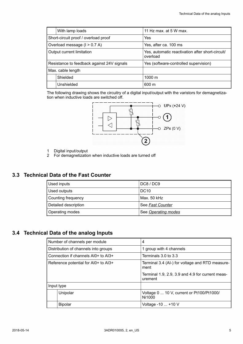
The following drawing shows the circuitry of a digital input/output with the varistors for demagnetiza-tion when inductive loads are switched off.
1 Digital input/output2 For demagnetization when inductive loads are turned off
3.3 Technical Data of the Fast CounterUsed inputs DC8 / DC9
Used outputs DC10
Counting frequency Max. 50 kHz
Detailed description See Fast Counter
Operating modes See Operating modes
3.4 Technical Data of the analog InputsNumber of channels per module 4
Distribution of channels into groups 1 group with 4 channels
Connection if channels AI0+ to AI3+ Terminals 3.0 to 3.3
Reference potential for AI0+ to AI3+ Terminal 3.4 (AI-) for voltage and RTD measure-ment
Terminal 1.9, 2.9, 3.9 and 4.9 for current meas-urement
Input type
Unipolar Voltage 0 ... 10 V, current or Pt100/Pt1000/Ni1000
Bipolar Voltage -10 ... +10 V
Technical Data of the analog Inputs
2018-05-14 3ADR010005, 2, en_US 5
Configurability 0...10 V, -10...+10 V, 0/4...20 mA, Pt100/1000,Ni1000 (each input can be configured individu-ally)
Channel input resistance Voltage: > 100 kW, current: ca. 330 W
Time constant of the input filter Voltage: 100 µs, current: 100 µs
Indication of the input signals 1 LED per channel (brightness depends on thevalue of the analog signal)
Conversion cycle 1 ms (for 4 inputs + 2 outputs); with RTDs Pt/Ni... 1 s
Resolution Range 0...10 V: 12 Bits
Range -10...+10 V: 12 Bits + sign
Range 0...20 mA: 12 Bits
Range 4...20 mA: 12 Bits
Range RTD (Pt100, PT1000, Ni1000): 0.1 °C
Conversion error of the analog values caused bynon-linearity, adjustment error at factory and reso-lution within the normal range
Typ. 0.5 %, max. 1 %
Relationship between input signal and hex code Tables Input Ranges Voltage, Current and Dig-ital Input and Input Range Resistor
Unused inputs Are configured as "unused" (default value)
Overvoltage protection Yes
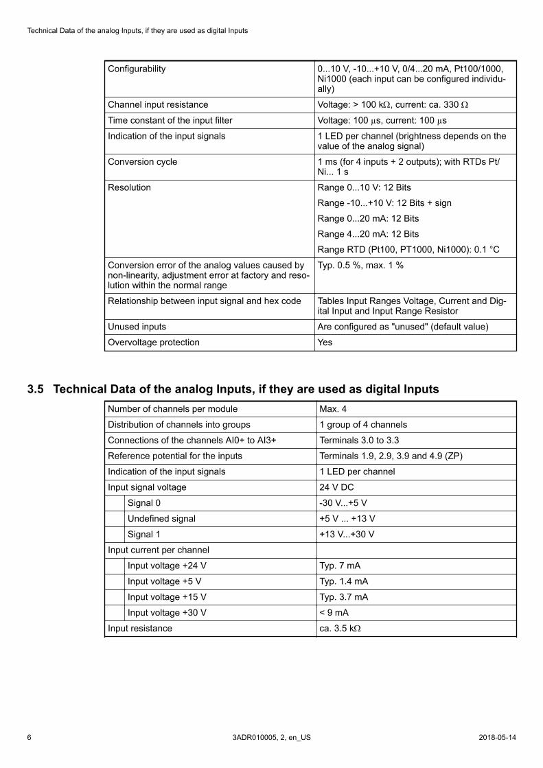
3.5 Technical Data of the analog Inputs, if they are used as digital InputsNumber of channels per module Max. 4
Distribution of channels into groups 1 group of 4 channels
Connections of the channels AI0+ to AI3+ Terminals 3.0 to 3.3
Reference potential for the inputs Terminals 1.9, 2.9, 3.9 and 4.9 (ZP)
Indication of the input signals 1 LED per channel
Input signal voltage 24 V DC
Signal 0 -30 V...+5 V
Undefined signal +5 V ... +13 V
Signal 1 +13 V...+30 V
Input current per channel
Input voltage +24 V Typ. 7 mA
Input voltage +5 V Typ. 1.4 mA
Input voltage +15 V Typ. 3.7 mA
Input voltage +30 V < 9 mA
Input resistance ca. 3.5 kW
Technical Data of the analog Inputs, if they are used as digital Inputs
2018-05-143ADR010005, 2, en_US6
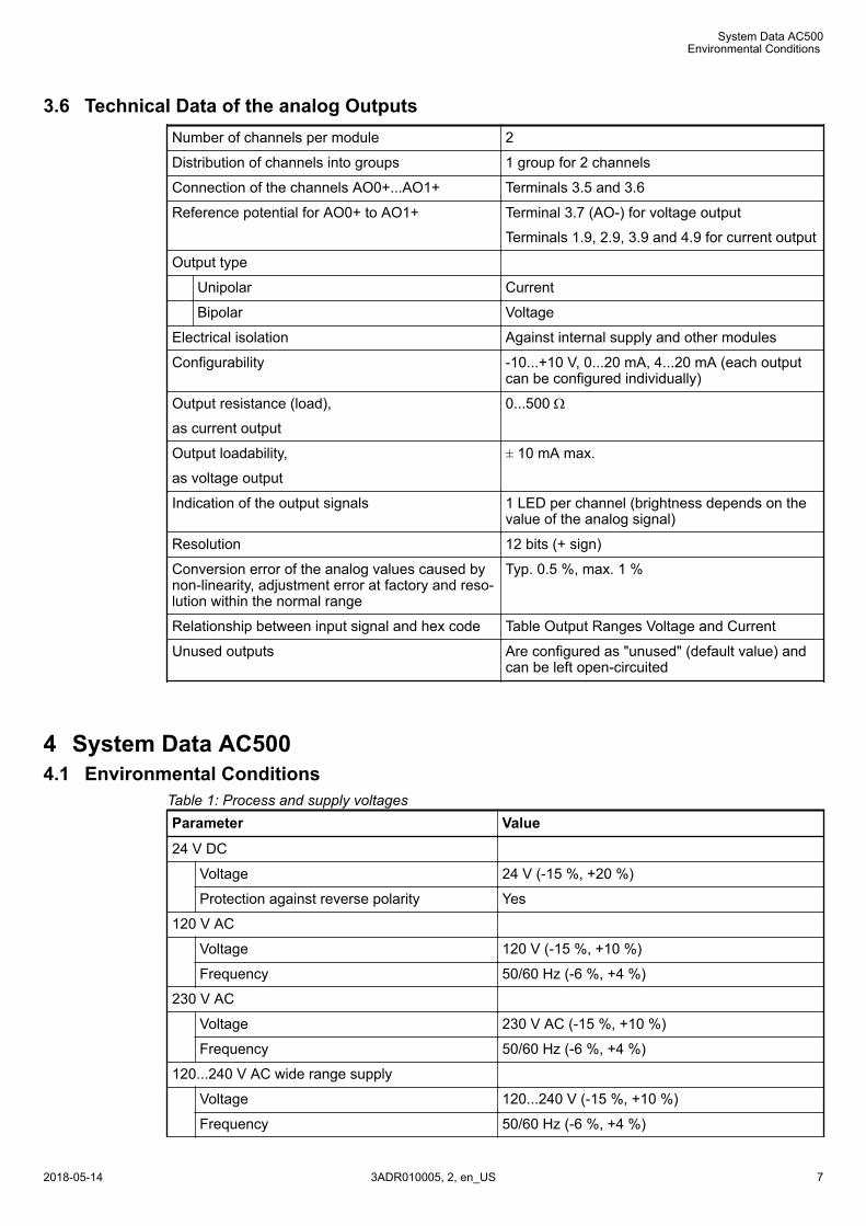
3.6 Technical Data of the analog OutputsNumber of channels per module 2
Distribution of channels into groups 1 group for 2 channels
Connection of the channels AO0+...AO1+ Terminals 3.5 and 3.6
Reference potential for AO0+ to AO1+ Terminal 3.7 (AO-) for voltage output
Terminals 1.9, 2.9, 3.9 and 4.9 for current output
Output type
Unipolar Current
Bipolar Voltage
Electrical isolation Against internal supply and other modules
Configurability -10...+10 V, 0...20 mA, 4...20 mA (each outputcan be configured individually)
Output resistance (load),
as current output
0...500 W
Output loadability,
as voltage output
± 10 mA max.
Indication of the output signals 1 LED per channel (brightness depends on thevalue of the analog signal)
Resolution 12 bits (+ sign)
Conversion error of the analog values caused bynon-linearity, adjustment error at factory and reso-lution within the normal range
Typ. 0.5 %, max. 1 %
Relationship between input signal and hex code Table Output Ranges Voltage and Current
Unused outputs Are configured as "unused" (default value) andcan be left open-circuited
4 System Data AC5004.1 Environmental Conditions
Table 1: Process and supply voltagesParameter Value
24 V DC
Voltage 24 V (-15 %, +20 %)
Protection against reverse polarity Yes
120 V AC
Voltage 120 V (-15 %, +10 %)
Frequency 50/60 Hz (-6 %, +4 %)
230 V AC
Voltage 230 V AC (-15 %, +10 %)
Frequency 50/60 Hz (-6 %, +4 %)
120...240 V AC wide range supply
Voltage 120...240 V (-15 %, +10 %)
Frequency 50/60 Hz (-6 %, +4 %)
System Data AC500
Environmental Conditions
2018-05-14 3ADR010005, 2, en_US 7
Parameter Value
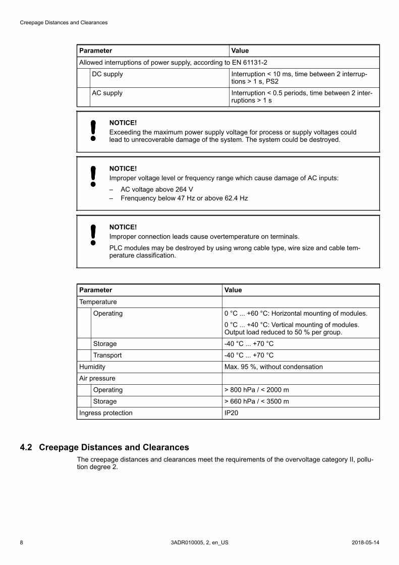
Allowed interruptions of power supply, according to EN 61131-2
DC supply Interruption < 10 ms, time between 2 interrup-tions > 1 s, PS2
AC supply Interruption < 0.5 periods, time between 2 inter-ruptions > 1 s
NOTICE!Exceeding the maximum power supply voltage for process or supply voltages couldlead to unrecoverable damage of the system. The system could be destroyed.
NOTICE!Improper voltage level or frequency range which cause damage of AC inputs:
– AC voltage above 264 V– Frenquency below 47 Hz or above 62.4 Hz
NOTICE!Improper connection leads cause overtemperature on terminals.
PLC modules may be destroyed by using wrong cable type, wire size and cable tem-perature classification.
Parameter Value
Temperature
Operating 0 °C ... +60 °C: Horizontal mounting of modules.
0 °C ... +40 °C: Vertical mounting of modules.Output load reduced to 50 % per group.
Storage -40 °C ... +70 °C
Transport -40 °C ... +70 °C
Humidity Max. 95 %, without condensation
Air pressure
Operating > 800 hPa / < 2000 m
Storage > 660 hPa / < 3500 m
Ingress protection IP20
4.2 Creepage Distances and ClearancesThe creepage distances and clearances meet the requirements of the overvoltage category II, pollu-tion degree 2.
Creepage Distances and Clearances
2018-05-143ADR010005, 2, en_US8
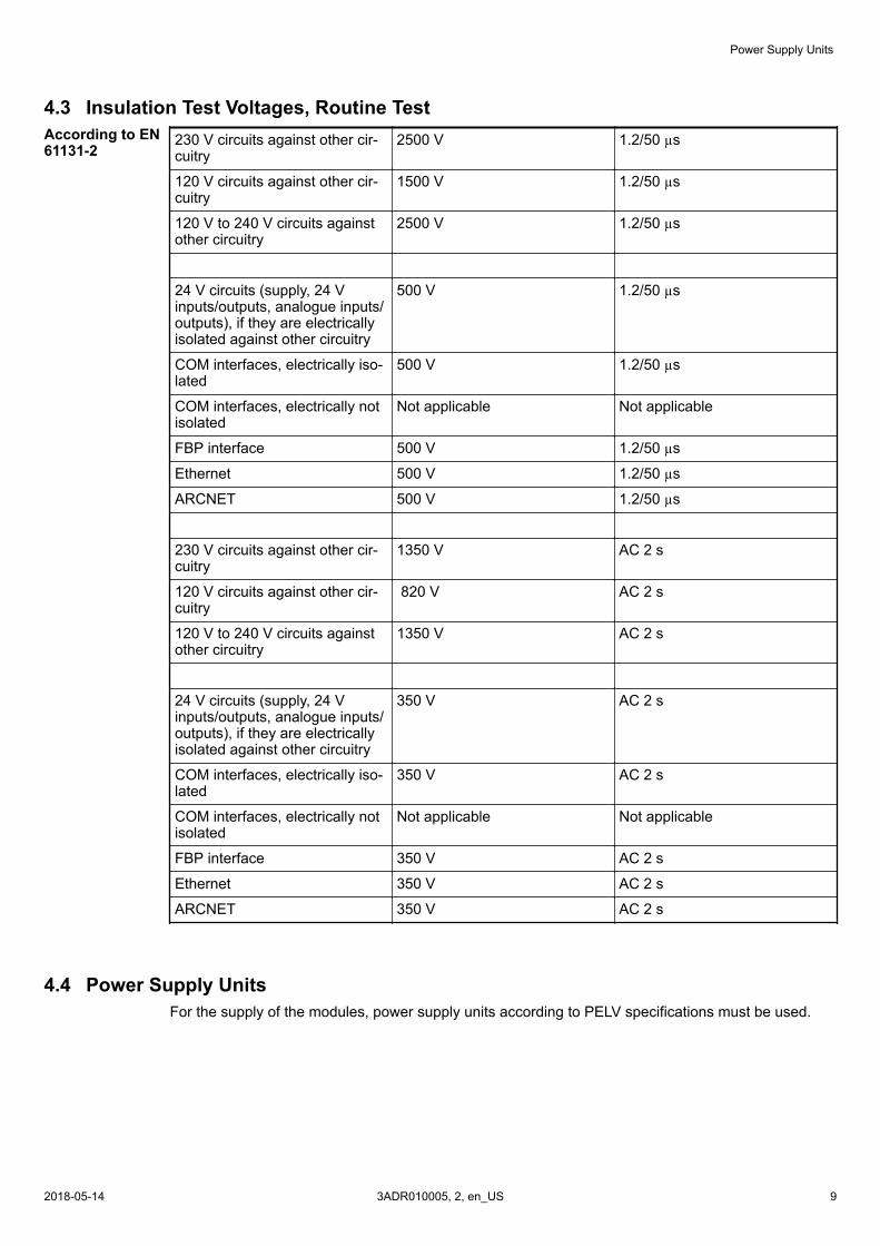
4.3 Insulation Test Voltages, Routine Test230 V circuits against other cir-cuitry
2500 V 1.2/50 µs
120 V circuits against other cir-cuitry
1500 V 1.2/50 µs
120 V to 240 V circuits againstother circuitry
2500 V 1.2/50 µs
24 V circuits (supply, 24 Vinputs/outputs, analogue inputs/outputs), if they are electricallyisolated against other circuitry
500 V 1.2/50 µs
COM interfaces, electrically iso-lated
500 V 1.2/50 µs
COM interfaces, electrically notisolated
Not applicable Not applicable
FBP interface 500 V 1.2/50 µs
Ethernet 500 V 1.2/50 µs
ARCNET 500 V 1.2/50 µs
230 V circuits against other cir-cuitry
1350 V AC 2 s
120 V circuits against other cir-cuitry
820 V AC 2 s
120 V to 240 V circuits againstother circuitry
1350 V AC 2 s
24 V circuits (supply, 24 Vinputs/outputs, analogue inputs/outputs), if they are electricallyisolated against other circuitry
350 V AC 2 s
COM interfaces, electrically iso-lated
350 V AC 2 s
COM interfaces, electrically notisolated
Not applicable Not applicable
FBP interface 350 V AC 2 s
Ethernet 350 V AC 2 s
ARCNET 350 V AC 2 s
4.4 Power Supply UnitsFor the supply of the modules, power supply units according to PELV specifications must be used.
According to EN61131-2
Power Supply Units
2018-05-14 3ADR010005, 2, en_US 9
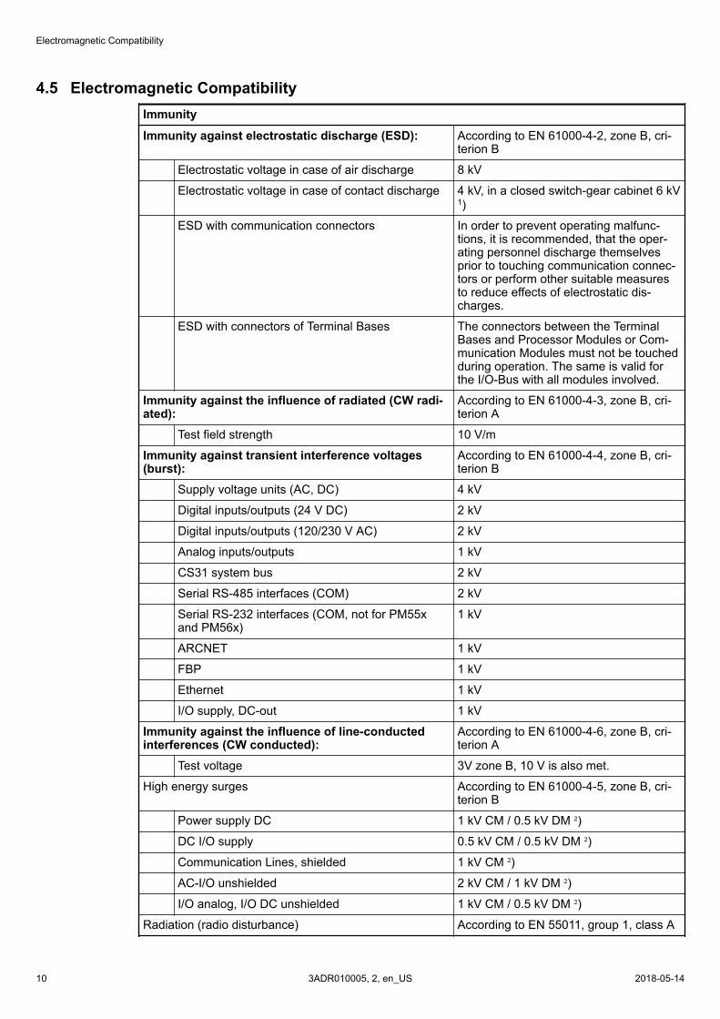
4.5 Electromagnetic CompatibilityImmunity
Immunity against electrostatic discharge (ESD): According to EN 61000-4-2, zone B, cri-terion B
Electrostatic voltage in case of air discharge 8 kV
Electrostatic voltage in case of contact discharge 4 kV, in a closed switch-gear cabinet 6 kV1)
ESD with communication connectors In order to prevent operating malfunc-tions, it is recommended, that the oper-ating personnel discharge themselvesprior to touching communication connec-tors or perform other suitable measuresto reduce effects of electrostatic dis-charges.
ESD with connectors of Terminal Bases The connectors between the TerminalBases and Processor Modules or Com-munication Modules must not be touchedduring operation. The same is valid forthe I/O-Bus with all modules involved.
Immunity against the influence of radiated (CW radi-ated):
According to EN 61000-4-3, zone B, cri-terion A
Test field strength 10 V/m
Immunity against transient interference voltages(burst):
According to EN 61000-4-4, zone B, cri-terion B
Supply voltage units (AC, DC) 4 kV
Digital inputs/outputs (24 V DC) 2 kV
Digital inputs/outputs (120/230 V AC) 2 kV
Analog inputs/outputs 1 kV
CS31 system bus 2 kV
Serial RS-485 interfaces (COM) 2 kV
Serial RS-232 interfaces (COM, not for PM55xand PM56x)
1 kV
ARCNET 1 kV
FBP 1 kV
Ethernet 1 kV
I/O supply, DC-out 1 kV
Immunity against the influence of line-conductedinterferences (CW conducted):
According to EN 61000-4-6, zone B, cri-terion A
Test voltage 3V zone B, 10 V is also met.
High energy surges According to EN 61000-4-5, zone B, cri-terion B
Power supply DC 1 kV CM / 0.5 kV DM ²)
DC I/O supply 0.5 kV CM / 0.5 kV DM ²)
Communication Lines, shielded 1 kV CM ²)
AC-I/O unshielded 2 kV CM / 1 kV DM ²)
I/O analog, I/O DC unshielded 1 kV CM / 0.5 kV DM ²)
Radiation (radio disturbance) According to EN 55011, group 1, class A
Electromagnetic Compatibility
2018-05-143ADR010005, 2, en_US10
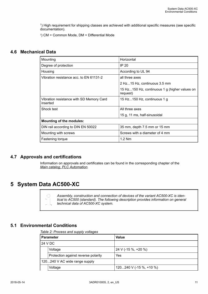
1) High requirement for shipping classes are achieved with additional specific measures (see specificdocumentation).
²) CM = Common Mode, DM = Differential Mode
4.6 Mechanical DataMounting Horizontal
Degree of protection IP 20
Housing According to UL 94
Vibration resistance acc. to EN 61131-2 all three axes
2 Hz...15 Hz, continuous 3.5 mm
15 Hz...150 Hz, continuous 1 g (higher values onrequest)
Vibration resistance with SD Memory Cardinserted
15 Hz...150 Hz, continuous 1 g
Shock test All three axes
15 g, 11 ms, half-sinusoidal
Mounting of the modules:DIN rail according to DIN EN 50022 35 mm, depth 7.5 mm or 15 mm
Mounting with screws Screws with a diameter of 4 mm
Fastening torque 1.2 Nm
4.7 Approvals and certificationsInformation on approvals and certificates can be found in the corresponding chapter of theMain catalog, PLC Automation.
5 System Data AC500-XC
Assembly, construction and connection of devices of the variant AC500-XC is iden-tical to AC500 (standard). The following description provides information on generaltechnical data of AC500-XC system.
5.1 Environmental ConditionsTable 2: Process and supply voltagesParameter Value
24 V DC
Voltage 24 V (-15 %, +20 %)
Protection against reverse polarity Yes
120...240 V AC wide range supply
Voltage 120...240 V (-15 %, +10 %)
System Data AC500-XC
Environmental Conditions
2018-05-14 3ADR010005, 2, en_US 11
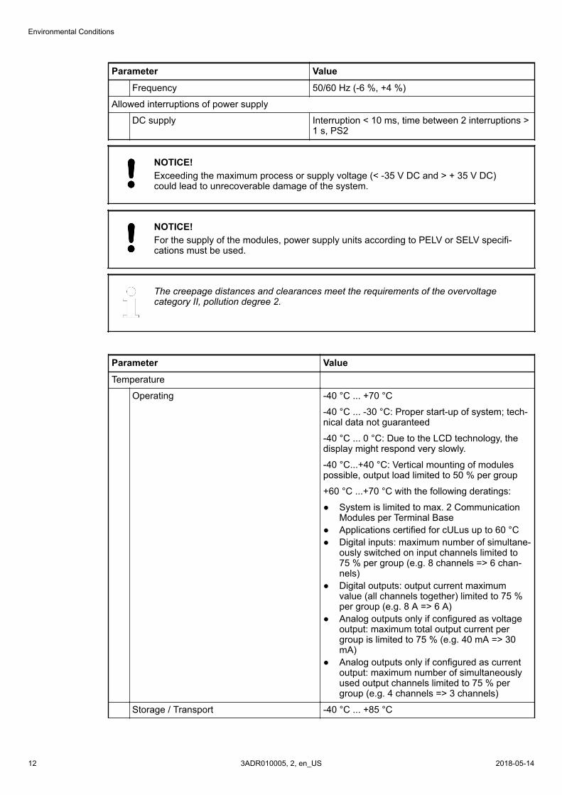
Parameter Value
Frequency 50/60 Hz (-6 %, +4 %)
Allowed interruptions of power supply
DC supply Interruption < 10 ms, time between 2 interruptions >1 s, PS2
NOTICE!Exceeding the maximum process or supply voltage (< -35 V DC and > + 35 V DC)could lead to unrecoverable damage of the system.
NOTICE!For the supply of the modules, power supply units according to PELV or SELV specifi-cations must be used.
The creepage distances and clearances meet the requirements of the overvoltagecategory II, pollution degree 2.
Parameter Value
Temperature
Operating -40 °C ... +70 °C
-40 °C ... -30 °C: Proper start-up of system; tech-nical data not guaranteed
-40 °C ... 0 °C: Due to the LCD technology, thedisplay might respond very slowly.
-40 °C...+40 °C: Vertical mounting of modulespossible, output load limited to 50 % per group
+60 °C ...+70 °C with the following deratings:
● System is limited to max. 2 CommunicationModules per Terminal Base
● Applications certified for cULus up to 60 °C● Digital inputs: maximum number of simultane-
ously switched on input channels limited to75 % per group (e.g. 8 channels => 6 chan-nels)
● Digital outputs: output current maximumvalue (all channels together) limited to 75 %per group (e.g. 8 A => 6 A)
● Analog outputs only if configured as voltageoutput: maximum total output current pergroup is limited to 75 % (e.g. 40 mA => 30mA)
● Analog outputs only if configured as currentoutput: maximum number of simultaneouslyused output channels limited to 75 % pergroup (e.g. 4 channels => 3 channels)
Storage / Transport -40 °C ... +85 °C
Environmental Conditions
2018-05-143ADR010005, 2, en_US12
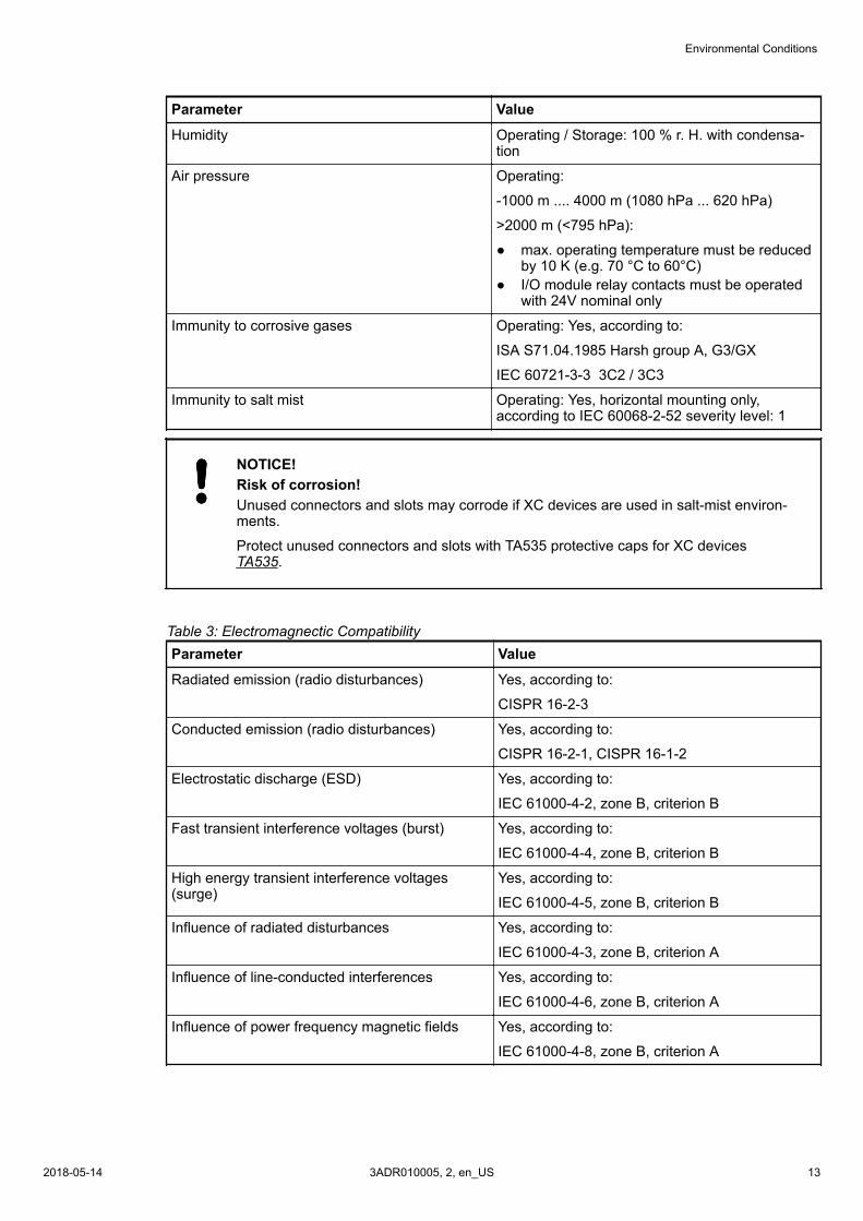
Parameter Value
Humidity Operating / Storage: 100 % r. H. with condensa-tion
Air pressure Operating:
-1000 m .... 4000 m (1080 hPa ... 620 hPa)
>2000 m (<795 hPa):
● max. operating temperature must be reducedby 10 K (e.g. 70 °C to 60°C)
● I/O module relay contacts must be operatedwith 24V nominal only
Immunity to corrosive gases Operating: Yes, according to:
ISA S71.04.1985 Harsh group A, G3/GX
IEC 60721-3-3 3C2 / 3C3
Immunity to salt mist Operating: Yes, horizontal mounting only,according to IEC 60068-2-52 severity level: 1
NOTICE!Risk of corrosion!Unused connectors and slots may corrode if XC devices are used in salt-mist environ-ments.
Protect unused connectors and slots with TA535 protective caps for XC devicesTA535.
Table 3: Electromagnectic CompatibilityParameter Value
Radiated emission (radio disturbances) Yes, according to:
CISPR 16-2-3
Conducted emission (radio disturbances) Yes, according to:
CISPR 16-2-1, CISPR 16-1-2
Electrostatic discharge (ESD) Yes, according to:
IEC 61000-4-2, zone B, criterion B
Fast transient interference voltages (burst) Yes, according to:
IEC 61000-4-4, zone B, criterion B
High energy transient interference voltages(surge)
Yes, according to:
IEC 61000-4-5, zone B, criterion B
Influence of radiated disturbances Yes, according to:
IEC 61000-4-3, zone B, criterion A
Influence of line-conducted interferences Yes, according to:
IEC 61000-4-6, zone B, criterion A
Influence of power frequency magnetic fields Yes, according to:
IEC 61000-4-8, zone B, criterion A
Environmental Conditions
2018-05-14 3ADR010005, 2, en_US 13
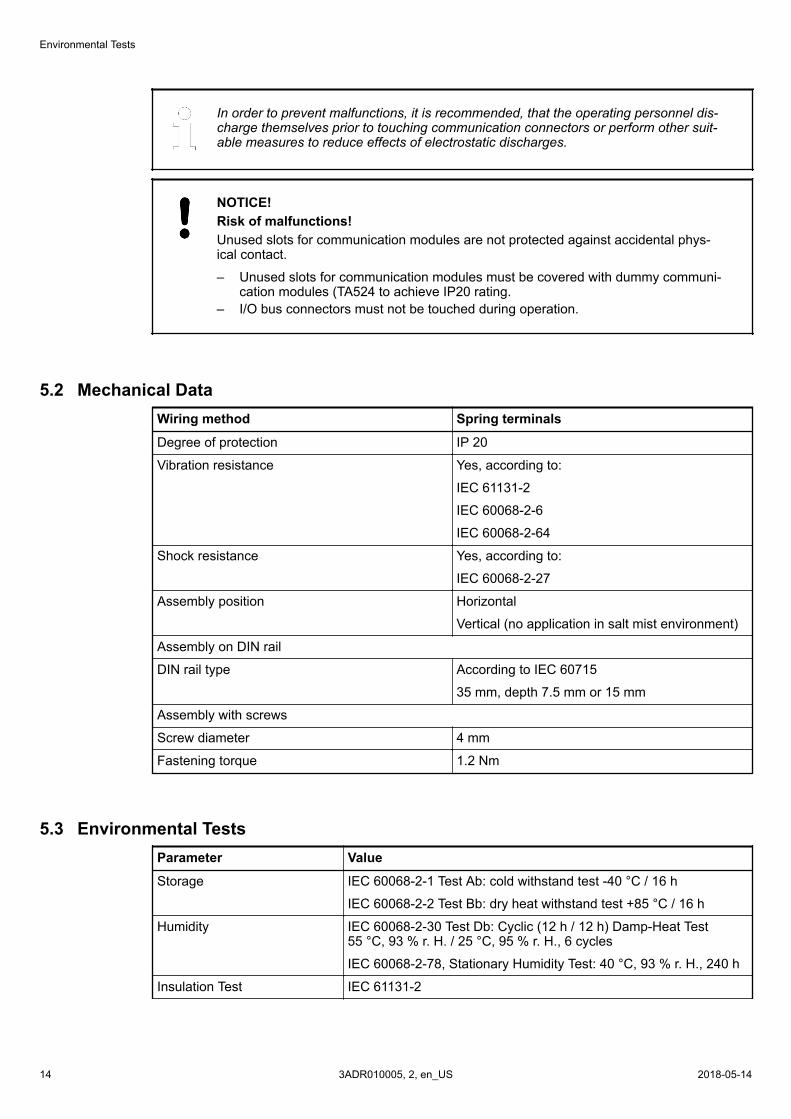
In order to prevent malfunctions, it is recommended, that the operating personnel dis-charge themselves prior to touching communication connectors or perform other suit-able measures to reduce effects of electrostatic discharges.
NOTICE!Risk of malfunctions!Unused slots for communication modules are not protected against accidental phys-ical contact.
– Unused slots for communication modules must be covered with dummy communi-cation modules (TA524 to achieve IP20 rating.
– I/O bus connectors must not be touched during operation.
5.2 Mechanical DataWiring method Spring terminals
Degree of protection IP 20
Vibration resistance Yes, according to:
IEC 61131-2
IEC 60068-2-6
IEC 60068-2-64
Shock resistance Yes, according to:
IEC 60068-2-27
Assembly position Horizontal
Vertical (no application in salt mist environment)
Assembly on DIN rail
DIN rail type According to IEC 60715
35 mm, depth 7.5 mm or 15 mm
Assembly with screws
Screw diameter 4 mm
Fastening torque 1.2 Nm
5.3 Environmental TestsParameter Value
Storage IEC 60068-2-1 Test Ab: cold withstand test -40 °C / 16 h
IEC 60068-2-2 Test Bb: dry heat withstand test +85 °C / 16 h
Humidity IEC 60068-2-30 Test Db: Cyclic (12 h / 12 h) Damp-Heat Test55 °C, 93 % r. H. / 25 °C, 95 % r. H., 6 cycles
IEC 60068-2-78, Stationary Humidity Test: 40 °C, 93 % r. H., 240 h
Insulation Test IEC 61131-2
Environmental Tests
2018-05-143ADR010005, 2, en_US14
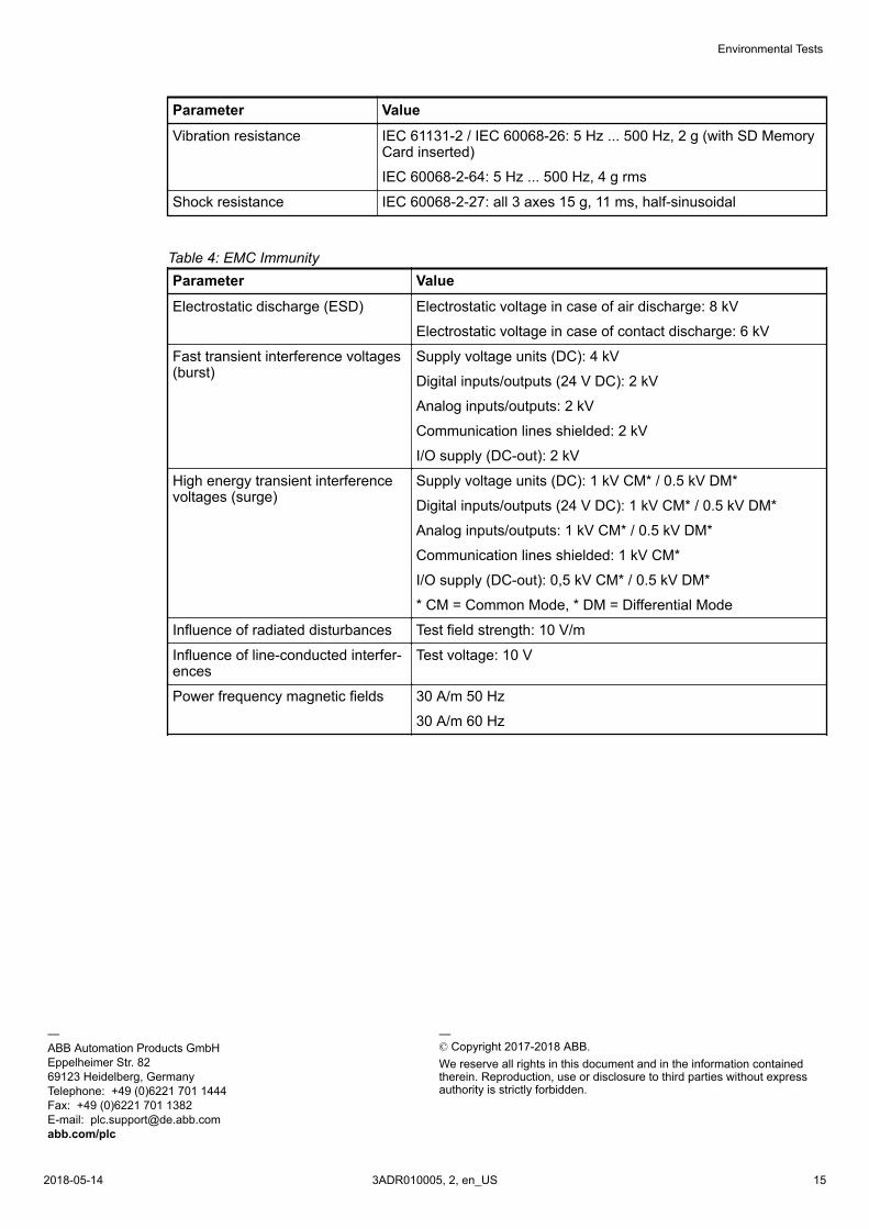
Parameter Value
Vibration resistance IEC 61131-2 / IEC 60068-26: 5 Hz ... 500 Hz, 2 g (with SD MemoryCard inserted)
IEC 60068-2-64: 5 Hz ... 500 Hz, 4 g rms
Shock resistance IEC 60068-2-27: all 3 axes 15 g, 11 ms, half-sinusoidal
Table 4: EMC ImmunityParameter Value
Electrostatic discharge (ESD) Electrostatic voltage in case of air discharge: 8 kV
Electrostatic voltage in case of contact discharge: 6 kV
Fast transient interference voltages(burst)
Supply voltage units (DC): 4 kV
Digital inputs/outputs (24 V DC): 2 kV
Analog inputs/outputs: 2 kV
Communication lines shielded: 2 kV
I/O supply (DC-out): 2 kV
High energy transient interferencevoltages (surge)
Supply voltage units (DC): 1 kV CM* / 0.5 kV DM*
Digital inputs/outputs (24 V DC): 1 kV CM* / 0.5 kV DM*
Analog inputs/outputs: 1 kV CM* / 0.5 kV DM*
Communication lines shielded: 1 kV CM*
I/O supply (DC-out): 0,5 kV CM* / 0.5 kV DM*
* CM = Common Mode, * DM = Differential Mode
Influence of radiated disturbances Test field strength: 10 V/m
Influence of line-conducted interfer-ences
Test voltage: 10 V
Power frequency magnetic fields 30 A/m 50 Hz
30 A/m 60 Hz
—ABB Automation Products GmbHEppelheimer Str. 8269123 Heidelberg, GermanyTelephone: +49 (0)6221 701 1444Fax: +49 (0)6221 701 1382E-mail: [email protected]/plc
—© Copyright 2017-2018 ABB.We reserve all rights in this document and in the information containedtherein. Reproduction, use or disclosure to third parties without expressauthority is strictly forbidden.
Environmental Tests
2018-05-14 3ADR010005, 2, en_US 15