Embed Size (px)
Citation preview

COMISIÓN DEINVESTIGACIÓNDE ACCIDENTESE INCIDENTES DEAVIACIÓN CIVIL
CIAIACCIAIAC
ReportIN-045/2004In-flight engine failureinvolving a McDonnellDouglas MD-83,registration EC-FTS,operated by Spanair,on 21 July 2004at Alicante Airport

Report
IN-045/2004
In-flight engine failure involving a McDonnell Douglas MD-83, registration EC-FTS, operated
by Spanair, on 21 July 2004 at Alicante Airport
COMISIÓN DE INVESTIGACIÓNDE ACCIDENTES E INCIDENTESDE AVIACIÓN CIVIL
SECRETARÍA GENERAL DETRANSPORTES

Edita: Centro de PublicacionesSecretaría General TécnicaMinisterio de Fomento ©
NIPO: 161-08-065-4Depósito legal: M. 23.129-2003Imprime: Diseño Gráfico AM2000
COMISIÓN DE INVESTIGACIÓN DE ACCIDENTES E INCIDENTES DE AVIACIÓN CIVIL
Tel.: +34 91 597 89 63 E-mail: [email protected] C/ Fruela, 6Fax: +34 91 463 55 35 http://www.ciaiac.es 28011 Madrid (España)

F o r e w o r d
This report is a technical document that reflects the point of view of the CivilAviation Accident and Incident Investigation Commission (CIAIAC) regardingthe circumstances of the event and its causes and consequences.
In accordance with the provisions of Law 21/2003 and pursuant to Annex 13of the International Civil Aviation Convention, the investigation is ofexclusively a technical nature, and its objective is not the assignment ofblame or liability. The investigation was carried out without havingnecessarily used legal evidence procedures and with no other basic aim thanpreventing future accidents.
Consequently, any use of this report for purposes other than that ofpreventing future accidents may lead to erroneous conclusions orinterpretations.
This report was originally issued in Spanish. This English translation isprovided for information purposes only.


v
Report IN-045/2004
T a b l e o f c o n t e n t s
Abbreviations ................................................................................................................................ vi
Synopsis ......................................................................................................................................... vii
1. Factual information ............................................................................................................... 1
1.1. History of the flight ........................................................................................................ 11.2. Injuries to persons .......................................................................................................... 21.3. Damage to aircraft ......................................................................................................... 21.4. Personnel information .................................................................................................... 2
1.4.1. Pilot information ............................................................................................... 31.4.2. Copilot information ........................................................................................... 3
1.5. Aircraft information ........................................................................................................ 41.5.1. Power plant ...................................................................................................... 51.5.2. Tailcone emergency exit .................................................................................... 71.5.3. Operator’s emergency procedure. Engine failure .............................................. 9
1.6. Meteorological information ............................................................................................ 101.7. Communications ............................................................................................................ 101.8. Aerodrome information .................................................................................................. 111.9. Flight recorders .............................................................................................................. 11
1.9.1. Flight data recorder ........................................................................................... 111.9.2. Cockpit voice recorder ...................................................................................... 14
1.10. Fire ................................................................................................................................. 151.11. Survival aspects .............................................................................................................. 151.12. Tests and research ......................................................................................................... 17
1.12.1. Engine disassembly report ............................................................................... 171.12.2. Tailcone slide inspection report ....................................................................... 19
1.13. Additional information ................................................................................................... 201.13.1. Information on previous engine failures and actions taken by Pratt & Whitney .. 201.13.2. Actions taken by the company to remedy the deficiencies noted in the in-fflight
engine failure procedure ................................................................................. 211.13.3. Company policy concerning emergency situations .......................................... 22
2. Analysis .................................................................................................................................. 23
2.1. Engine failure ................................................................................................................. 232.2. Failure of the inflatable evacuation slide at the aft exit to deploy ................................. 242.3. Emergency management aboard the aircraft ................................................................. 242.4. Engine failure procedure ................................................................................................ 252.5. Actions of firefighting and evacuation personnel ........................................................... 26
3. Conclusions ............................................................................................................................ 29
3.1. Findings .......................................................................................................................... 293.2. Causes ........................................................................................................................... 29
4. Safety recommendations ...................................................................................................... 31

Report IN-045/2004
vi
A b b r e v i a t i o n s
00° Degree(s)00 °C Degrees centigradeATC Air Traffic ControlCIAIAC Civil Aviation Accident and Incident Investigation Commission (Spain)CSN Cycles since newCRM Crew resource managementCVR Cockpit voice recorderDC Douglas CorporationDFDR Digital flight data recorderEGT Exhaust gas temperatureEPR Engine pressure ratioFCU Fuel control unitFF Fuel flowFL Flight levelft FeetFOD Foreign object damageh Hour(s)HPC High pressure compressorHPT High pressure turbineILS Instrument landing systemIR(A) Instrumental Rating (A)kg Kilogram(s)kt Knot(s)lb Pound(s)LH Left handLPC Low pressure compressorLPT Low pressure turbinem Meter(s)MD McDonnell DouglasMTOW Maximum takeoff weightN1 Engine fan speedN2 Engine compressor speedQNH Altimeter setting to obtain altitude above sea levelrpm Revolutions per minuteS/N Serial numberSB Service bulletinTACC Terminal Area Control CenterTSN Time since newUTC Coordinated universal timeVOR VHF omnidirectional range
vii
Report IN-045/2004
S y n o p s i s
Owner and operator: Finansskandic AB and Spanair
Aircraft: McDonnell Douglas, MD-83
Date and time of incident: 21 July 2004; 12:41 h1
Place of incident: Alicante Airport
Persons aboard and injuries: 152, 19 passengers and 1 person on the ground, minorinjuries
Type of flight: Commercial Air Transport. Schedule. Domestic.Passengers
Date of approval: 28th May 2008
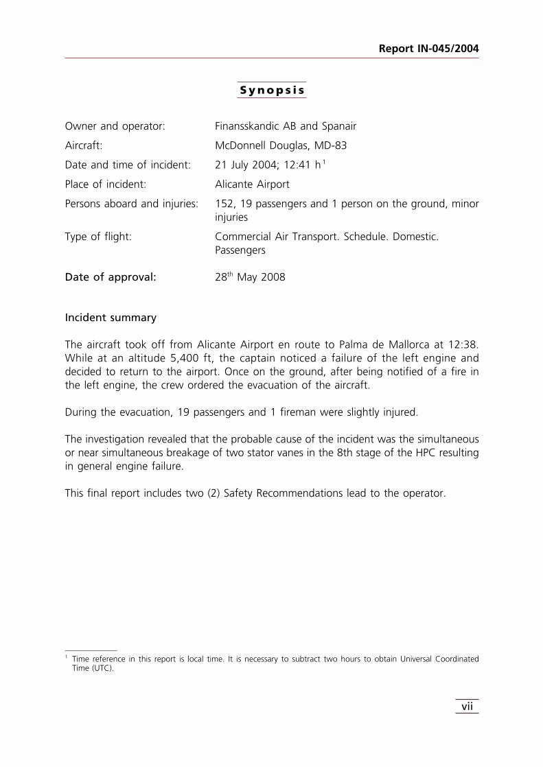
Incident summary
The aircraft took off from Alicante Airport en route to Palma de Mallorca at 12:38.While at an altitude 5,400 ft, the captain noticed a failure of the left engine anddecided to return to the airport. Once on the ground, after being notified of a fire inthe left engine, the crew ordered the evacuation of the aircraft.
During the evacuation, 19 passengers and 1 fireman were slightly injured.
The investigation revealed that the probable cause of the incident was the simultaneousor near simultaneous breakage of two stator vanes in the 8th stage of the HPC resultingin general engine failure.
This final report includes two (2) Safety Recommendations lead to the operator.
1 Time reference in this report is local time. It is necessary to subtract two hours to obtain Universal CoordinatedTime (UTC).

1. FACTUAL INFORMATION
1.1. History of the flight
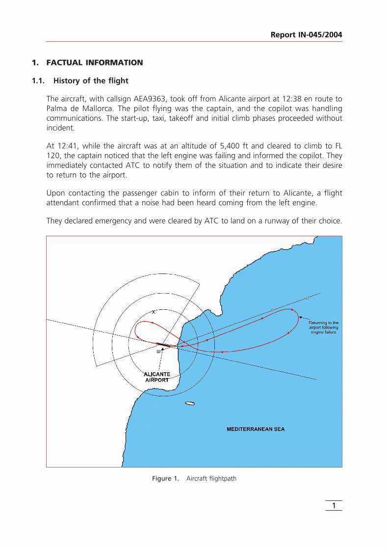
The aircraft, with callsign AEA9363, took off from Alicante airport at 12:38 en route toPalma de Mallorca. The pilot flying was the captain, and the copilot was handlingcommunications. The start-up, taxi, takeoff and initial climb phases proceeded withoutincident.
At 12:41, while the aircraft was at an altitude of 5,400 ft and cleared to climb to FL120, the captain noticed that the left engine was failing and informed the copilot. Theyimmediately contacted ATC to notify them of the situation and to indicate their desireto return to the airport.
Upon contacting the passenger cabin to inform of their return to Alicante, a flightattendant confirmed that a noise had been heard coming from the left engine.
They declared emergency and were cleared by ATC to land on a runway of their choice.
Figure 1. Aircraft flightpath
1
Report IN-045/2004

They initiated the engine failure emergency checklist three times, but failed to completeit due to interruptions from ATC personnel and, the last time, because they deemed itnecessary to focus on the landing itself.
They were cleared to land on runway 10. The crew decided to make a visual approach.
They finished the before landing checklist and the landing proceeded normally. Once onthe ground, the aircraft left the runway via taxiway C4 and stopped, notifying ATC thatthey were clear of the runway.
After being informed by ATC of a fire in the left engine, the crew decided to evacuatethe aircraft. No fire warnings were received for the left engine.
During the evacuation, 19 passengers and one firefighter were slightly injured.
Airport emergency response teams applied fire extinguishing agents to the left turbinewhere they had seen the fire.
Although the tailcone was jettisoned, the slide did not deploy.
1.2. Injuries to persons
Injuries Crew Passengers Total in the aircraft Others
Fatal
Serious
Minor 19 19 Not applicable
None 6 127 133 Not applicable
TOTAL 6 146 152 1
1.3. Damage to aircraft
Damage to the aircraft was limited to the left engine.
1.4. Personnel information
The aircraft crew consisted of the pilot, copilot, the purser and 3 flight attendants.
Report IN-045/2004
2

1.4.1. Pilot information
The most relevant information concerning the captain of the aircraft is as follows:
Pilot information
Age 35 years old
Nationality Spanish
License Airline transport pilot (since 12 Feb 1997)
Ratings (expiration) DC9 80/MD88/MD90 (until 22 Mar 2005)
IR(A) (until 22 Mar 2005)
Exp. Total 7,361 h
On the type 6,860 h
Last 90 days 154 h
Last 60 days 124:17 h
Last 30 days 29:35 h
Activity Time flight activity began 07:25 h
Previous rest 72 h
Medical certificate Type Class 1
Date Valid until 02 Feb 2005
The pilot had completed two courses on CRM in the 6 months prior to the incident.The CRM courses consisted of 3 parts: the first provided theoretical information usingaudiovisual techniques, the second presented practical cases also using audiovisualtechniques, and in the third they held training exercises together with the cabin crew.
He had also taken 1 periodic theoretical refresher course and 2 periodic simulatorrefresher courses.
1.4.2. Copilot information
The most relevant information concerning the copilot of the aircraft is as follows:
Copilot information
Age 37 años
Nationality Española
License Piloto comercial de aeronave (desde 17-02-1998)
Ratings (expiration) DC9 80/MD88/MD90 (hasta 18-05-2005)
IR(A) (hasta 18-05-2005)
3
Report IN-045/2004
Copilot information (continuation)
Exp. Total No available
On the type No available
Last 90 days 171:35 h
Last 60 days 120:40 h
Last 30 days 70:10 h
Activity Time flight activity began 07:25 h
Previous rest Over 48 h
Medical certificate Type Class 1
Date Valid until 10 Jan 2005
The copilot had not taken any CRM courses in the 6 months prior to the incident.
He had taken 1 periodic theoretical refresher course and 5 periodic simulator refreshercourses.
1.5. Aircraft information
The MD-83 is a narrow-body passenger turbojet aircraft with a medium range and a155-172-passenger capacity, depending on the version. Its design evolved from that ofthe Douglas Corporation DC-9, following that company’s merger with McDonnell Co.The McDonnell Douglas Corporation was then bought by Boeing, which is responsiblefor the type certificate.
The aircraft’s most relevant data are listed below:
General information
Registration EC-FTS
Manufacturer McDonnell Douglas Corporation
Model Douglas MD-83
Serial number 49621
Year of manufacture 1988
Engine 1 Manufacturer Pratt & Whitney
Model JT8D-219
Serial number 728179
Report IN-045/2004
4

General information (continuation)
Engine 2 Manufacturer Pratt & Whitney
Model JT8D-219
Serial number 718143
Technical characteristics
Dimensions Wingspan 107.8 ft
Height 29.6 ft
Lenght 147.9 ft
Restrictions MTOW 160,000 lb
Minimum crew 2 pilots
1.5.1. Power plant
The MD-83 power plant consists of two Pratt & Whitney JT8D-219 engines. This enginemodel is a medium bypass dual spool turbofan with a single stage fan, a six-stage LPCand a seven-stage HPC. It has nine combustion chambers in a can-annular arrangement.The HPT has one stage, while the LPT features three stages. The exhaust consists of afluid mixing stage and an exhaust nozzle.
The engine has a rated takeoff thrust of 21,700 lb at an ambient temperature of up to28.8º C. At ambient temperatures above 28.8º C, the allowable thrust is reduced so asnot to exceed the gas temperature limit at the turbine intake.
The EGT limit at takeoff power is 625º C, and the revolution limits are 8,350 rpm(101.6%) N1 and 12,550 rpm (102%) N2. The EPR2 limit at takeoff power at sea levelwith temperatures below 28º C is 2.034.
The following data are from the number one engine installed on the Spanair aircraft:
Manufacturer: Pratt & Whitney
Model: JT8D-219
Engine: #1 (LH)
Serial number (S/N): 728179
5
Report IN-045/2004
2 The EPR (engine pressure ratio) is the ratio between the total pressure of the gases at the exhaust and thecompressor intake. In this type of engine, EPR is the primary indicator of thrust.

Time since new (TSN): 10,642
Cycles since new (CSN): 7,675
Hours since last inspection: 1,673 h
Cycles since last inspection: 895
Date of last inspection: 9 Jun 2003
Time since installation: 334 h
Cycles since installation: 218 h
Date of installation: 9 Jun 2004
Spanair was operating the engine S/N 728179, owned by Willis Lease Finance Company,under a rental agreement. Before being installed on the Spanair aircraft, the engine hadbeen inspected after accumulating 1339 hours and 677 cycles on other aircraft since itslast workshop inspection. Said inspection, made in February of 2004, consisted of start-up and vibration checks, and a visual and boroscopic inspection of the turbine area.
During the previous inspection, made in June of 2003, the engine was disassembled torepair both the HPC eighth stage stator and sulfidation of the LPT second stage blades.
The engine maintenance schedule calls for an inspection of the “8th Support andShroud (pre SB 6117)” every four months.
A summary of the history of the number 1 engine is shown below:
Engine maintenance information
Engine repaired Engine hours 8,969 h
Engine cycles 6,780
Repair start date 1 Oct 2002
Repair finish date 9 Jun 2003
Description During the previous heavy maintenanceactivity in June of 2003, the engine wasdisassembled to pepair both the HPC eighthstage stator and sulfidation of the LPT secondstage blades.
Last engine inspection Engine hours 10,308 h(prior to installation on
Engine cycles 7,457aircraft EC-FTS)Date 19 Feb 2004
Description Engine checked and tested. Boroscopicinspection performed.
Report IN-045/2004
6

Engine maintenance information (continuation)
Engine installed on Aircraft hours 50,670 haircraft EC-FTS
Aircraft cycles 29,698
Engine hours 10,308 h
Engine cycles 7,457
Date 9 Jun 2004
Status on date of Aircraft hours 51,004 hincident
Aircraft cycles 29,916
Engine hours 10,642 h
Engine cycles 7,675
Date 21 Jul 2004
According to information from the DFDR, the number one engine exceeded 638 °C ofEGT, which is the hightest temperature logged, and the EPR fell below one, that is, itlost all thrust. Two compressor stalls3 were felt, with both high and low rotor rpm’sdropping sharply, though they kept turning. The crew placed that engine’s throttle leverat idle and did not execute the engine shutdown procedure until after landing. The fuelflow decreased noticeably, though a reading of 0 was never recorded on the DFDR. Nofire warnings were received for the engine.
1.5.2. Tailcone emergency exit
The aircraft has an emergency exit in the tailcone at the aft end of the passenger cabin.If the emergency exits are armed and the handle located in the door of the aftpassenger entrance is actuated, the tailcone detaches and the slide deploysautomatically.
The tailcone exit may be actuated from three different places: the passenger afterentrance door, using a handle on the inside of the tailcone (non-pressurized area), andusing another handle on the outside of the aircraft.
When the tailcone emergency exit is actuated, the tailcone is release and falls. It thenturns 90° and moves to the left side of the aircraft to keep the tailcone from interferingwith the deployment of the slide.
7
Report IN-045/2004
3 A compressor stall occurs when the amount of airflow through the last stages of the compressor is less than theairflow at the compressor intake, as a result of which the airflow in the initial stages slows and their blades stallaerodynamically. This phenomenon leads to a reversal of air flow that is felt as a detonation or a bang.

Figure 2. Tailcone jettison system
As it falls, it pulls on the slide container via the slide lanyard, moving it next to thetailcone, leaving the slide exposed so it can deploy and inflate.
Report IN-045/2004
8

Figure 3. Low drag tailcone translation system
The command to release the tailcone and deploy the slide employs a set of clasps andcables which are attached to a bar on the door and to the clamping bolts on thetailcone and on the slide release system using various rings, velcro strips and automaticbuttons. These components must be set correctly if the release command is to beproperly transmitted.
1.5.3. Operator’s emergency procedure. Engine failure
The emergency procedure described in the operator’s Operations Manual for an in-flightengine failure and which the crew used is as follows:
Note: Plan to land at the nearest Emergency airport
1. Autothrottle ............................................................................... OFF.2. Throttle, affected engine ........................................................... IDLE.
ENGINE FAILURE
9
Report IN-045/2004

3. Eng sync .................................................................................... OFF.4. Engine Instruments .................................................................... OBSERVE.
N1 or N2 or OIL PRESS indicate zero or any other indication of severe damage.
CAUTION.Prior to performing item 5. L/P and R/P must verifythat correct fire handle is selected.
5. Fire handle, affected engine ...................................................... PULL.6. Fuel crossfeed ............................................................................ ON.7. Perform ENGINE SHUTDOWN Checklist, this section8. [End of procedure]
N1, N2 and OIL PRESS indicate a rotating and undamaged engine.
9. At PiC discretion: Perform IN FLIGHT ENGINE START Check list, thissection Check fuel balance and use crossfeed as required
10. [End of procedure]
The crew was unable to complete the engine failure procedure.
1.6. Meteorological information
Weather data for the surroundings at the time of the incident are as follows:
At 10:00:
07009KT 040V120 9999 FEW015 SCT025 BKN200 27/20 Q1015 NOSIG=
At 10:30:
08010KT 050V120 9999 FEW015 SCT025 28/20 Q1015 NOSIG=
At 11:00
08010KT 050V110 9999 FEW015 SCT025 28/20 Q1016 NOSIG=
1.7. Communications
During the flight, the aircraft was in contact with Alicante tower and with TACCValencia. After landing and coming to a stop on taxiway C-4, the control towerinformed the crew of a fire in the left engine.
All communications were carried out without incident.
Report IN-045/2004
10
1.8. Aerodrome information
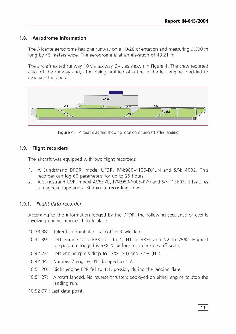
The Alicante aerodrome has one runway on a 10/28 orientation and measuring 3,000 mlong by 45 meters wide. The aerodrome is at an elevation of 43.21 m.
The aircraft exited runway 10 via taxiway C-4, as shown in Figure 4. The crew reportedclear of the runway and, after being notified of a fire in the left engine, decided toevacuate the aircraft.
Figure 4. Airport diagram showing location of aircraft after landing
1.9. Flight recorders
The aircraft was equipped with two flight recorders:
1. A Sundstrand DFDR, model UFDR, P/N:980-4100-DXUN and S/N: 4002. Thisrecorder can log 60 parameters for up to 25 hours.
2. A Sundstrand CVR, model AV557C, P/N:980-6005-079 and S/N: 13603. It featuresa magnetic tape and a 30-minute recording time.
1.9.1. Flight data recorder
According to the information logged by the DFDR, the following sequence of eventsinvolving engine number 1 took place:
10:38:38: Takeoff run initiated, takeoff EPR selected.
10:41:39: Left engine fails. EPR falls to 1, N1 to 38% and N2 to 75%. Highesttemperature logged is 638 °C before recorder goes off scale.
10:42:22: Left engine rpm’s drop to 17% (N1) and 37% (N2).
10:42:44: Number 2 engine EPR dropped to 1.7.
10:51:20: Right engine EPR fell to 1.1, possibly during the landing flare.
10:51:27: Aircraft landed. No reverse thrusters deployed on either engine to stop thelanding run.
10:52:07 : Last data point.
11
Report IN-045/2004

Figure 5. Progression of the exhaust temperature and EPR for both engines during the flight
Report IN-045/2004
12

Figure 6. Progression of rpm’s and fuel flow for both engines during the flight
13
Report IN-045/2004

In the seconds prior to the failure of the left engine, the average engine parameterswere as follows:
Engine N1 (%) N2 (%) EPR EGT (°C) FF (kg/h)
#1 90.64 95.03 1.844 540 4,137
#2 89.78 95.49 1.808 550 4,038
At no time was the fire warning for the number 1 engine received.
1.9.2. Cockpit voice recorder
The first mention by the captain of the left engine failure appears on the CVR at10:41:44. During the emergency, the captain was the pilot flying, while the copilot wasin charge of communications and emergency management.
An emergency was declared and ATC notified at 10:41:55. They were then asked if theywanted to return to the airport, and they were informed that they could turn around,going rightward.
At 10:42:44, they were informed by ATC that runway 28 was available but had a strongtailwind gusting up to 14 kt. The crew expressed a preference for runway 10, and ATCinstructed them to proceed to the VOR and that they could make a VOR approach, ILSor visual.
At 10:43:27, the crew informed the cabin attendants of the engine failure and that theywere returning to Alicante.
At 10:43:50, the captain called for the approach checklist. The copilot noted they hadnot performed any emergency checklists.
At 10:44:06, the copilot initiated the descent checklist, in keeping with the company’sOperations Manual. She was interrupted by a QNH report from ATC.
At 10:44:23, the copilot resumed the checklist.
At 10:44:28, she completed the descent checklist. The captain expressed his desire notto start the engine and asked the copilot to shut it down.
At 10:44:56, just as the copilot was starting the engine failure checklist, ATC contactedthe aircraft, informing them they were the only traffic and asking if they were going tomake a visual approach.
Report IN-045/2004
14

At 10:45:23, they confirmed their intention to make a visual approach.
At 10:45:38, the copilot did the approach checklist and the captain reiterated hisintention to shut down the engine.
At 10:46:02, ATC requested information on the number of passengers aboard.
At 10:46:31, the copilot started the engine failure checklist once again.
At 10:46:42, the captain insisted the engine was damaged.
At 10:46:44, ATC instructed the crew to contact the control tower.
At 10:47:15, they informed the control tower they were entering left downwind.
At 10:47:51, the copilot resumed the engine failure checklist, with the pilot insistingonce again that he shut it down. The copilot started the engine failure checklist but wasinterrupted by the landing gear warning.
At 10:49:13, they performed the before landing checklist.
At 10:50:02, they acknowledged they were clear to land.
At 10:51:32, they landed.
At 10:51:58, they reported clear of the runway.
At 10:52:07, they were informed about the fire in the left engine, after which theydecided to evacuate the aircraft.
1.10. Fire
Once disassembled, the engine showed no signs of external fire.
At no time were flames seen issuing from the left turbine.
1.11. Survival aspects
Once the emergency was declared, the airport firefighting service was alerted. Threevehicles were dispatched to combat the emergency. The vehicles were situated at theintersection of exits A-2, C-2 and C-4 with A-1, C-1 and C-3, respectively, as shown inthe figure.
15
Report IN-045/2004
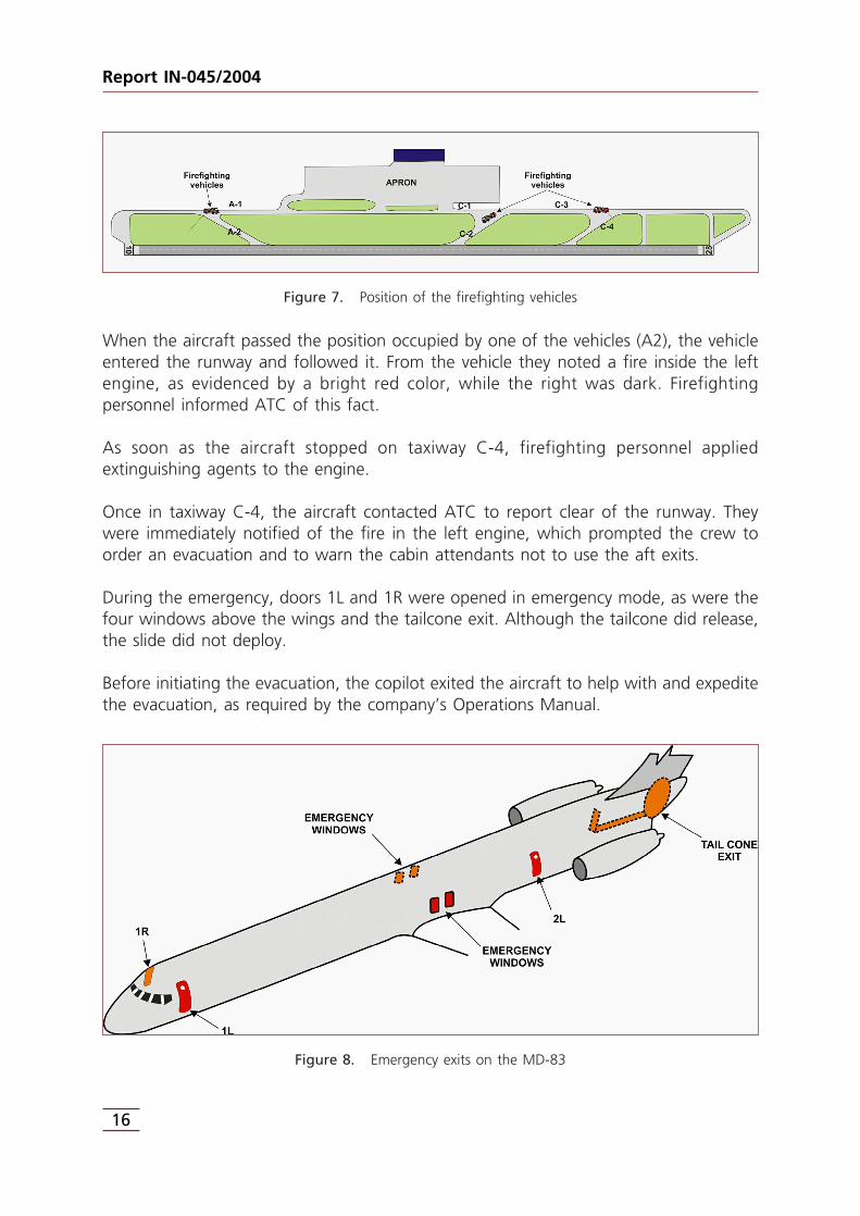
Figure 7. Position of the firefighting vehicles
When the aircraft passed the position occupied by one of the vehicles (A2), the vehicleentered the runway and followed it. From the vehicle they noted a fire inside the leftengine, as evidenced by a bright red color, while the right was dark. Firefightingpersonnel informed ATC of this fact.
As soon as the aircraft stopped on taxiway C-4, firefighting personnel appliedextinguishing agents to the engine.
Once in taxiway C-4, the aircraft contacted ATC to report clear of the runway. Theywere immediately notified of the fire in the left engine, which prompted the crew toorder an evacuation and to warn the cabin attendants not to use the aft exits.
During the emergency, doors 1L and 1R were opened in emergency mode, as were thefour windows above the wings and the tailcone exit. Although the tailcone did release,the slide did not deploy.
Before initiating the evacuation, the copilot exited the aircraft to help with and expeditethe evacuation, as required by the company’s Operations Manual.
Figure 8. Emergency exits on the MD-83
Report IN-045/2004
16

The evacuation was carried out quickly, mainly via doors 1L and 1R, since the passengersdid not want to jump from the windows onto the wings. Neither the tailcone nor exit2L were used.
Once the passengers were safely off, the cabin crew gathered some of the survival gearand exited the aircraft.
Nineteen passengers and one firefighter were slightly injured during the evacuation andtreated in the airport’s facilities. The injuries were the result of friction burns, bruises,excoriations, panic attacks and a gash.
Once outside the aircraft, the cabin crew rounded up the passengers so they could betransported to the airport terminal aboard the airside buses. Two of the passengers weretaken by ambulance to the airport clinic.
1.12. Tests and research
1.12.1. Engine disassembly report
The left engine, S/N 728179, was removed from the aircraft after the incident and takento a workshop, where it was thoroughly disassembled and inspected.
The disassembly report details the damage. Data from said report was used to draft asummary of the engine’s condition after the in-flight failure, provided below.
Before the disassembly, the report noted the absence of both fire on the outside of theengine and of any fuel or oil leaks. The engine’s fire detection systems were functioningproperly. The LPC rotated freely but the HPC had seized.
Turbine and exhaust areas
All the blades in the 1st stage of the HPT, and those in the 2nd and 3rd stages of theLPT burned off uniformly. All the blade roots remained in the disk slots and only someblade tips from the fourth stage were found among the debris. The forward faces ofthe front knife-edge seals exhibit heavy metal spray, but the knife-edge seals exhibit nounusual tip rub.
There were no impacts or excessive friction of rotating components, indicating theabsence of any significant imbalance in the turbine during the failure sequence. It isbelieved that the tips of the blades from the 4th stage detached while the turbine wasrotating slowly.
17
Report IN-045/2004

The LPT and HPT cases showed no distortion or bulging and no impact marks to theouter shrouds; their casing inside were covered in molten or half-molten metal.
Turbine exhaust case was visually intact and no gas leak had occurred from the primaryflowpath to the fan, though the heat had caused the aluminum fairings to warp andpartially melt.
Diffuser
Fuel lines to fuel nozzles were intact, there were no leaks.
Metal splatter was found on the combustor can domes. This is characteristic ofcompressor airfoil failures.
HPC area, compressor stages 7 to 13
In stages 9 to 13 of the HPC, all the rotor blades were fractured, bent, rubbed downor liberate from their blade slots, though many of their roots were still in place.
The stator vanes of stages 9 to 13 were damaged, but practically all remained in place.
During the disassembly minor damage to the 7th stage were observed.
Six adjacent vanes detached from the 8th stage stator. All the remaining blades in stator8 were damaged, especially along their trailing edges.
When the first two vanes in the8th stage stator detached, theyleft a stub in the outer shroudwhich was consistent with aknown failure mode. The failurestart in High Cycle Fatigue at thetrailing edge braze joint with theouter shroud and propagatestowards the leading edge,leaving an about 5 mm stub atthe leading edge.
The other four detached statorvanes showed signs of havingbeen torn off as the result of animpact.
Report IN-045/2004
18
Figure 9. Fatigue failure of the vane

Another vane from the 8th stage stator showed a trailing edge crack originating at theouter end braze.
All the 8th stage rotor blades were heavily rubbed and torn along their trailing edges.
The knife-edge seals of the disk spacers showed evidence of asymmetric rub consistentwith imbalance having caused the rub of the 8th stage disk bore to the LPT shaft.
The outer shroud of the HPC 8th stage rotor was heavily battered and bulged outwards.
LPC stages 1 to 6 and fan area
There was no evidence of FOD. Minor damage typical of stall phenomena was notedon the tips of fan blades and on the leading edge of other blades.
Conclusion of the disassembly report
In light of the damage, it is believed that the engine failure resulted from thesimultaneous or near simultaneous released of two vanes on the 8th stage stator as aresult of High Cycle Fatigue cracking, which led to the breakage of 4 other vanes onthe 8th stage stator. Downstream damage then occurred in stages 9 to 13. The generalfailure of the compressor caused successive increase in turbine entry temperature andeventually turbine overheat to the point of melting turbine airfoils.
Based on its condition, it appears that an auto-shutdown probably occurred, prior topilot action, caused by the fuel flow being cut off as a result of the N2 dropping belowthe speed required to sustain the engine running. Thus, there was probably an emissionof smoke from the hot debris rather than an active fire on landing. The failure was fullycontained (debris exited onlythrough the tailpipe) and noengine fire occurred.
The fire warning loops installed onthe engine were serviceable.
1.12.2. Tailcone slide inspectionreport
An inspection of the tailcone slidedid not reveal any defects. It wasconcluded that an improperinstallation had kept it fromdeploying.
19
Report IN-045/2004
Figure 10. HPC 8th stage stator
Faced with this possibility, the company took the initiative of inspecting all the tailconeslides in its MD80 fleet without finding any discrepancies.
1.13. Additional information
1.13.1. Information on previous engine failures and actions taken by Pratt & Whitney
In January of 2004, the manufacturer, Pratt & Whitney, published a document entitled“JT8D-200 All Operator Wire: JT8D/72-36/CTS:WRM:04-01-19-1”, which it reported ontwo incidents involving similar circumstances and one operator. 3 day later, on 22nd ofJanuary 2004, an update of this document entitled “JT8D-200 All Operator Wire:JT8D/72-36/CTS:CRC:04-22-1” was issued. This document also stated that the risk of adouble engine failure was remote and that corrective actions were, therefore,unnecessary.
After the disassembly of the engine in a previous incident in May of the same year, P& W published an update to the document (JT8D-200 All Operator Wire: JT8D/72-36/CTS:CRC:04-05-28-1), explaining the failure mechanism due to crack initiation andpropagation in high cycle fatigue, initiating at the trailing edge o the vanes an the innerlocation of the outer shroud. Pratt & Whitney was aware of thirty-six liberations of 8th
stage stator vanes related to brazed stators since 1990. None of these events hadresulted in case penetration; fourteen of these events had resulted in an In Flight ShutDown.
There were no reports of 8th stage stator vane cracking at the trailing edges in newproduction strap welded stator assemblies.
It additionally states that while the failure mechanism could depend on the type ofoperations involved, the braze of the vanes should be adequate for most types ofoperations and complies with all safe operating requirements, insisting that the risk ofa double engine failure in flight is extremely remote.
A different document (Special Instruction No. 1F-04, Boroscope procedure for 8th stagestator vanes, Feb 2004) provides instructions for the on wing preventive inspection ofengines, though said inspection is generally not required or even recommended.
Later, on 6 May 2005, a Service Bulletin was issued (SBJT8D 6472, Engine-statorassembly, 8th stage compressor-conversion from a braze-repaired to a strap-weldedconfiguration) which provide a modification which converts braze-repaired 8th and 9th
stage compressor stator assemblies to the original strap welded configuration. Thenecessity and convenience of its implementation was left to the operators’ discretiondepending on their situation.
Report IN-045/2004
20

1.13.2. Actions taken by the company to remedy the deficiencies noted in the in-flight engine failure procedure
During the investigation, it was noted that the company’s procedure for an in-flightengine failure was ambiguous and led to incorrect determinations by the crewconcerning whether or not the engine was damaged, so it could be shut down, or not,so it could be restarted.
After being informed of this fact, the company took the following actions:
1. The company’s procedures committee analyzed the engine failure checklist. Themanufacturer and another operator were also consulted on its suitability. Eventually,it was decided not to modify said procedure.
2. Several engine failures were included in the simulator training program during thefirst half of 2007, with special emphasis being placed on explaining and clarifyingthe engine failure procedure.
3. An explanation was included of the engine failure procedure in bulletin number 13of the company’s MD fleet, published on 10 April 2007, which clarifies the meaningof the phrase “any other indication of severe damage,” as shown below:
Figure 11. Explanation of the engine failure procedure
21
Report IN-045/2004

1.13.3. Company policy concerning emergency situations
According to information provided by company personnel, whenever an in-flightemergency takes place, the tasks sharing is such that one member of the flight crew ischarged with controlling the aircraft and handling communications while the othermanages the emergency.
Report IN-045/2004
22

2. ANALYSIS
2.1. Engine failure
It became apparent during the left engine disassembly that the initial fault was the high-cycle fatigue failure of two stator vanes on the 8th stage. The engine had accumulated10,642 flying hours and 7,675 cycles since new, and only 1,673 flying hours and 895cycles since the last workshop inspection of these stator vanes.
Just before the left engine failure, FDR readings were normal compared to those of theright engine and well below the limits for EGT, N1 and N2. Of the allowed time forapplying takeoff power, 5 minutes, only 3 had elapsed since the start of the takeoffrun.
The absence of impact damage to previous compressor stages excludes the possibilityof FOD to the engine. Likewise, the good condition of the oil and fuel systems precludeother possible failure mechanisms.
The released vanes led to the breakage of four other vanes in the same stator (8th), aswell as minor damage to the 7th stage. The released components triggered a cascadeof failures in later stages of the compressor which were compounded by the imbalanceof rotating elements. The imbalance was obviously a result of the stage 8 stator failure,and not vice versa.
The general failure of the HPC inhibited the air from the air intake from reaching thecompressor exit, resulting in a compressor stall and a drop in rpm’s.
In the combustion and turbine area, the decreased quantity of air caused a successiveincrease in turbine entry temperature and eventually turbine overheat to the point ofmelting turbine airfoils.
Since the main fuel pump is driven through the main accessory gearbox by the HPT/HPC,the drop in N2 caused a loss of fuel pressure. This loss of fuel pressure could have alsocut off the fuel supply from the FCU and the pressurization and dump valve, such thatthe engine shut itself down (flame out) and stopped the flow of fuel into the combustorthat could have fed an internal engine fire. The engine fire reported by the firefightingservice, then, was rather the smoke and molten metal being ejected from the engineexhaust.
The failure was completely contained by the engine case, and all material ejected frominside the engine did so via the exhaust nozzle.
The fire detection system did not activate the fire alarm precisely because no fire existed,which kept the fire warning from reaching a high enough temperature to be actuated.
23
Report IN-045/2004

Subsequently, in May of 2005, Pratt & Whitney issued a Service Bulletin (SBJT8D 6472,Engine-stator assembly, 8th stage compressor-conversion from a braze-repaired to astrap-welded configuration), in response to both the case in question and to previousoccurrences. Application of the Service Bulletin was left to each operator’s discretion.Pratt and Whitney informed that in addition to no engine fire had resulted in any of theevents, the determination of Service Bulletin classification is based on a number offactors, including flight safety considerations.
2.2. Failure of the inflatable evacuation slide at the aft exit to deploy
According to the inspection, the tailcone slide failed to deploy because of animproperly installed actuating device. Fortunately on this occasion, the type of failure,namely a reported fire in the left engine, prompted the captain to specifically prohibitthe aft section from being used during the evacuation, though the tailcone was stillreleased.
Had it been necessary to evacuate via the aft section, the first passengers may havebeen pushed out the tailcone door by other passengers, resulting in much more seriousinjuries than those actually produced.
Given the serious consequences than a malfunctioning tailcone slide may have had, theactions taken by the company in checking its remaining fleet to verify proper tailconeinstallation and assembly are considered adequate from a safety standpoint.
The release of the tailcone itself, however, is considered inappropriate given the flightcrew’s specific warning not to use the aft exits.
2.3. Emergency management aboard the aircraft
The copilot was handling communications, the emergency procedure and the checklistswhile the captain was in control of the aircraft. This task sharing during an emergencysituation is inconsistent with company policy.
The engine failure took place at an altitude of 5,400 ft. From then on until the landing,the copilot performed the normal descent, approach and before landing checklists, andstarted the emergency checklist for an “In-flight engine failure” on several occasions,without completing it, in addition to handling ATC communications.
The captain identified the engine failure at 10:41:44, after which they immediatelydecided to return to Alicante.
Report IN-045/2004
24

From the time they informed approach control of the emergency until they weretransferred to the control of Alicante tower at 10:47:15, approach control contactedthe aircraft five times.
Each time the copilot was forced to interrupt one of the checklists (descent, approachor engine failure) in order to respond.
The pilot told the copilot that they were going to stop the engine at 10:44:28, since hewas convinced the engine was damaged, but the copilot did not understand himcorrectly until 10:47:51, her intention being to restart the engine each time she initiatedthe engine failure checklist. Whenever they talked about the condition of the engine,they were interrupted by a communication from ATC that kept them from clarifying thispoint.
What led the copilot to act in this manner was the in-flight engine failure procedureand an observation of the parameters indicated therein (N1, N2 and oil pressure), whichled her to conclude that the engine was undamaged.
After the captain’s insistence that the engine was damaged, they started the enginefailure list with the intention of shutting it down, but were forced to interrupt it to focuson the landing once the Landing Gear warning was come out.
This type of engine cuts off the fuel flow once fuel pressure ( as detemined by N2) dropsbelow a minimum value, which prevented the addition of fuel to the combustor whichcould have fueled a core fire and the consequences such an event could have hadduring the flight. The crew’s most proper course of action would have been to shutdown the engine immediately once they were convinced it was damaged.
The combination of having the copilot handle both communications and the enginefailure procedure, along with the interruptions from ATC and the ambiguity of theprocedure itself, prevented the crew from acting more effectively. Allocating tasks inaccordance with company policy and having a better-defined engine failure procedurewould have facilitated the full execution of the engine failure procedure.
Of special note is the lack of knowledge on the part of ATC personnel of the tasks thatmust be completed by a crew during an emergency. The resulting interruptions by ATCpersonnel in trying to aid in the emergency efforts actually have the opposite effect ona crew that is trying to complete these tasks.
2.4. Engine failure procedure
Completing the engine failure procedure requires making a determination of whetheror not the engine is damaged.
25
Report IN-045/2004

This procedure takes into account N1, N2 and oil pressure as indicators to be used bythe crew in objectively evaluating whether or not the engine is damaged.
The procedure also refers to “any other indication of severe damage.” This phrase isambiguous and does not give the pilot a chance to make a quick assessment by notingany one specific engine parameter, making him instead focus his attention solely on N1,N2 and oil pressure.
The text as it currently reads does not explicitly consider any other engine parameters,such as a violation of EGT (which happened during the incident), oil quantity, etc., todetermine if the engine is severely damaged.
Since in this incident, N1, N2 and oil pressure did not indicate zero, the copilotconcluded that the engine was not damaged.
For his part, the captain was convinced that the engine was in fact damaged, andinsisted that the engine not be restarted.
At any rate, the procedure was not completed essentially because it was not easy toascertain whether or not the engine was damaged. In fact, using the informationavailable to the crew, the conclusion could have been reached, following the procedure,that the engine was undamaged.
This lack of specifics led the crew to not shut down the engine.
The operator, once informed of this deficiency in the procedure, took various actions,such as evaluating the procedure, including several engine failures in its trainingprogram for the first half of 2007, and, lastly, adding an explanation of the enginefailure procedure in bulletin 13 of the MD fleet.
Following the evaluation of the procedure, it was decided not to change it, and thoughthe other measures taken by the company are satisfactory, they are insufficient toprevent the same confusion that took place during this incident from happening again.It is thus advisable to redefine when the engine is “damaged” or “undamaged” in theengine failure procedure.
2.5. Actions of firefighting and evacuation personnel
Following the aircraft’s notification that it was returning to the airport and itsdeclaration of an emergency, ATC informed firefighting services of the event. Threevehicles were swiftly deployed along the runway to minimize the response time.
Once the aircraft landed, they proceeded to extinguish what at first seemed like a firein the left engine. Though it was later discovered, once the engine was disassembled,
Report IN-045/2004
26

that there had in fact been no fire, the response to a possible fire situation was correctnevertheless.
Informing ATC and ATC quickly informing the crew which, in turn, ordered theevacuation, were all considered adequate responses to what could been an emergencysuch as having a fire in the left engine.
Also rapid was the evacuation of the passengers and the response of airport medicalservices at the scene. The transport of the passengers to the airport terminal wasaccomplished in a brief period of time.
27
Report IN-045/2004


3. CONCLUSIONS
3.1. Findings
• The flight crew was licensed and qualified for the flight.• The aircraft was maintained in accordance with regulations.• The engine that failed was being operated within EPR, EGT and rpm (N1 and N2)
limits.• The fault occurred suddenly, three minutes after takeoff power was selected on both
engines.• No outside causes, such as FOD, were involved.• The initial fault was tracked to the 8th stage stator of the HPC.• The crew decided to return to the airport once the emergency took place.• Task sharing during the emergency was not in accordance with company procedures.• The captain may have believed the engine to be damaged, and requested the copilot
to shut it down.• As the copilot worked through the engine failure procedure, she concluded that the
engine was undamaged and insisted on restarting it.• The engine fire warning was not come out during the flight.• The in-flight engine failure emergency procedure was not completed.• The landing and taxiing were completed with the left engine not shut down and its
fuel throttle in the IDLE position.• ATC reported the existence of a fire in the left engine following the report from the
firefighting service to that effect.• The crew ordered the evacuation of the aircraft.• The tailcone slide was actuated.• The tailcone slide did not deploy when the door was opened in emergency mode.• A disassembly of the engine showed no signs that there had been a fire in the
engine.
3.2. Causes
It is believed that the incident was caused by the simultaneous or near simultaneousfatigue failure of two vanes in the 8th stage stator, which led to the subsequent failuresdownstream and to the general failure of the engine.
29
Report IN-045/2004


4. SAFETY RECOMMENDATIONS
An analysis of the in-flight engine failure procedure and of its performance during thisincident resulted in some deficiencies being noted in the definition of said procedure. Itis considered that the ambiguity of some of the steps to be taken slows down andconfuses the crew when it comes time to assess the situation and make decisions. Thefollowing recommendation is therefore made:
REC 09/2008. It is recommended that Spanair perform a review of the in-flight enginefailure procedure such that the crew can use a quick evaluation ofobjective parameters to determine whether or not the engine isdamaged.
Another aspect to consider is that during the emergency, task sharing was not inkeeping with company policy, resulting in an excessive workload for the copilot andwhich may have, in turn, contributed to the partial completion of the engine failureemergency procedure. This aspect should be addressed during the company’s CRM andrefresher (simulator) courses. The following recommendation is issued as a result:
REC 10/2008. It is recommended that Spanair stress the training aspects related toproper task sharing at the cockpit during emergency situations in all ofits Type Qualification, Refresher and CRM courses.
The operator informed about its intention of undertaking actions designed to spreadand stress the emergency situation concept through the department in charge of thetraining related to Crew Resource Management (CRM).
31
Report IN-045/2004