Embed Size (px)
Citation preview
CIFECENTER FOR INTEGRATED FACILITY ENGINEERING
Building Energy Performance Simulation Tools -
a Life-Cycle and Interoperable Perspective
By
Tobias Maile, Martin Fischer & Vladimir Bazjanac
CIFE Working Paper #WP107 DECEMBER 2007
STANFORD UNIVERSITY

COPYRIGHT © 2007 BY Center for Integrated Facility Engineering
If you would like to contact the authors, please write to:
c/o CIFE, Civil and Environmental Engineering Dept., Stanford University
Terman Engineering Center Mail Code: 4020
Stanford, CA 94305-4020
Building energy performance simulation tools – a life-cycle and interoperable perspective
Working Paper
Tobias Maile1&2, Martin Fischer1, Vladimir Bazjanac2
1 CIFE (Center for Integrated Facility Engineering) at Stanford University
2 EETD (Environmental Energy Technology Division) at LBNL (Lawrence Berkeley National Laboratory)
Abstract
Energy simulation tools are increasingly used for analysis of energy performance of buildings and the thermal comfort of their occupants. This paper describes a selection of energy simulation engines and user interfaces that are capable of these analyses today. Specifically, it discusses the usage of these tools over different life-cycle stages. Besides a brief overview about energy simulation concepts, the paper illustrates each tool’s strengths and weaknesses as well as its data exchange capabilities. Given the significant variety of such energy simulation tools, it is crucial to understand limitations of the tools and the complexity of such simulations. The reliability of data exchange and straightforward, user-friendly interfaces are major aspects of the practical usage of these tools. Due to the huge amount of input data and the availability of rich 3D geometry models effective data exchange and software interfaces are crucial to enable faster and more reliable energy performance simulation analysis.
i
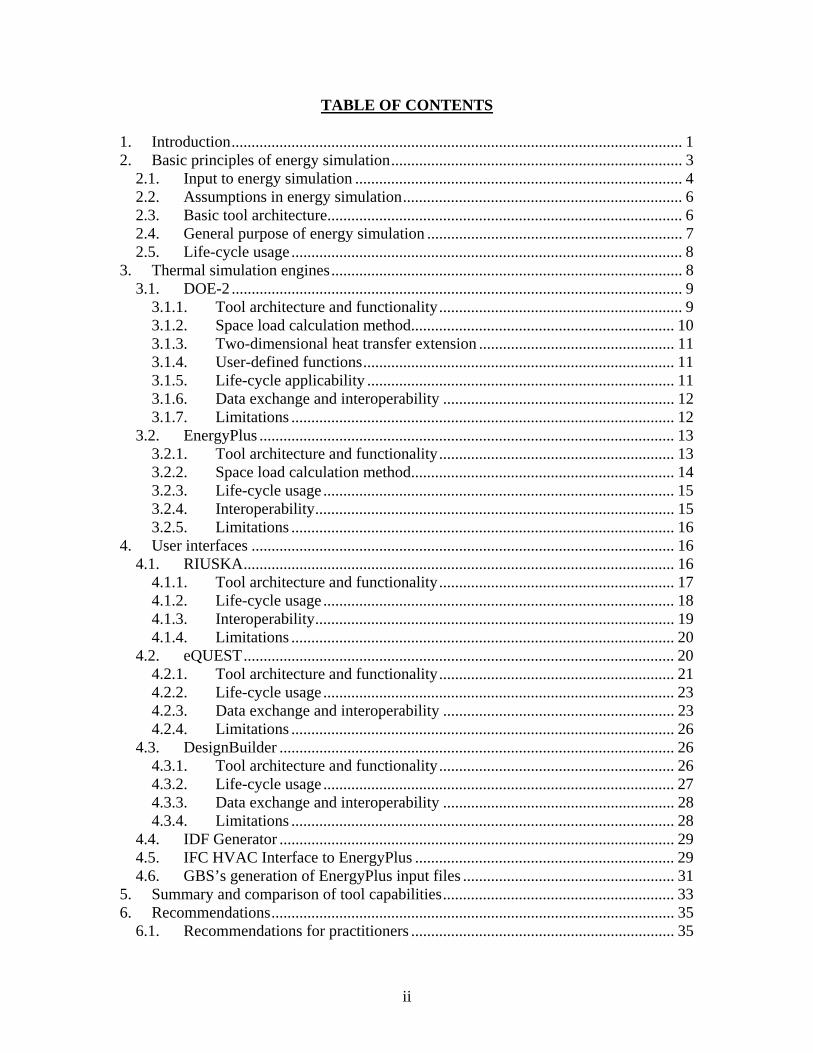
TABLE OF CONTENTS 1. Introduction................................................................................................................. 1 2. Basic principles of energy simulation......................................................................... 3
2.1. Input to energy simulation .................................................................................. 4 2.2. Assumptions in energy simulation...................................................................... 6 2.3. Basic tool architecture......................................................................................... 6 2.4. General purpose of energy simulation ................................................................ 7 2.5. Life-cycle usage .................................................................................................. 8
3. Thermal simulation engines........................................................................................ 8 3.1. DOE-2 ................................................................................................................. 9
3.1.1. Tool architecture and functionality............................................................. 9 3.1.2. Space load calculation method.................................................................. 10 3.1.3. Two-dimensional heat transfer extension ................................................. 11 3.1.4. User-defined functions.............................................................................. 11 3.1.5. Life-cycle applicability ............................................................................. 11 3.1.6. Data exchange and interoperability .......................................................... 12 3.1.7. Limitations ................................................................................................ 12
3.2. EnergyPlus ........................................................................................................ 13 3.2.1. Tool architecture and functionality........................................................... 13 3.2.2. Space load calculation method.................................................................. 14 3.2.3. Life-cycle usage ........................................................................................ 15 3.2.4. Interoperability.......................................................................................... 15 3.2.5. Limitations ................................................................................................ 16
4. User interfaces .......................................................................................................... 16 4.1. RIUSKA............................................................................................................ 16
4.1.1. Tool architecture and functionality........................................................... 17 4.1.2. Life-cycle usage ........................................................................................ 18 4.1.3. Interoperability.......................................................................................... 19 4.1.4. Limitations ................................................................................................ 20
4.2. eQUEST............................................................................................................ 20 4.2.1. Tool architecture and functionality........................................................... 21 4.2.2. Life-cycle usage ........................................................................................ 23 4.2.3. Data exchange and interoperability .......................................................... 23 4.2.4. Limitations ................................................................................................ 26
4.3. DesignBuilder ................................................................................................... 26 4.3.1. Tool architecture and functionality........................................................... 26 4.3.2. Life-cycle usage ........................................................................................ 27 4.3.3. Data exchange and interoperability .......................................................... 28 4.3.4. Limitations ................................................................................................ 28
4.4. IDF Generator ................................................................................................... 29 4.5. IFC HVAC Interface to EnergyPlus ................................................................. 29 4.6. GBS’s generation of EnergyPlus input files ..................................................... 31
5. Summary and comparison of tool capabilities.......................................................... 33 6. Recommendations..................................................................................................... 35
6.1. Recommendations for practitioners .................................................................. 35
ii
6.2. Recommendations for researchers .................................................................... 37 7. Conclusion ................................................................................................................ 40 8. Acknowledgements................................................................................................... 40
TABLE OF FIGURES Figure 1: 3D Model of Senate Properties Headquarters rendered in ArchiCAD ............... 2 Figure 2: General data flow of simulation engines............................................................. 3 Figure 3: Difference between walls and space boundaries................................................. 4 Figure 4: General architecture of energy simulation tools.................................................. 7 Figure 5: Dataflow of the DOE-2.1 engine (Birdsall et al. 1990)....................................... 9 Figure 6: EnergyPlus data flow (EnergyPlus 2005) ......................................................... 14 Figure 7: Basic workflow of a RIUSKA simulation......................................................... 17 Figure 8: Basis HVAC system configuration in RIUSKA ............................................... 18 Figure 9: 3D-view of the example building in RIUSKA when building was imported via
IFC ............................................................................................................... 20 Figure 10: Wizards in eQUEST........................................................................................ 21 Figure 11: General workflow in the schematic design wizard of eQUEST ..................... 22 Figure 12: Example air loop in eQUEST.......................................................................... 23 Figure 13: Data exchange capabilities of eQUEST .......................................................... 24 Figure 14: DWG import in eQUEST................................................................................ 24 Figure 15: 3D-view of the example building in eQUEST when building geometry was
imported via Green Building Studio ............................................................ 25 Figure 16: DesignBuilder workflow ................................................................................. 27 Figure 17: DXF import in DesignBuilder......................................................................... 28 Figure 18: Dataflow of the IFC interfaces ........................................................................ 30 Figure 19: 3D-view of the example building when building geometry was imported into
EnergyPlus via Green Building Studio ........................................................ 32 Figure 20: Overview of geometry data exchange ............................................................. 33 Figure 21: Ideal workflow for energy performance simulation tools ............................... 36
TABLE OF TABLES
Table 1: Comparison of functionalities between DOE-2 and EnergyPlus ....................... 33 Table 2: Comparison of functionality of RIUSKA, eQUEST, DesignBuilder, IDF
Generator and IFC HVAC Interface ............................................................ 34
iii
1. Introduction
Energy performance simulation programs are powerful tools to study energy performance and thermal comfort during the building’s life-cycle. Today, numerous such tools are available and they differ in many ways; in their thermodynamic models, their graphical user interfaces, their purpose of use, their life-cycle applicability, and their ability to exchange data with other software applications.
Most of the thermal simulation programs consist of a so-called engine, which enables detailed thermal simulations based on simple text-based input and output files. These engines contain mathematical and thermodynamic algorithms that are used to calculate the energy performance according to the underlying model of the engine. Most important for the practical use of these tools is a graphical user interface that eases the generation of input and the analysis of output, and exposes the functionality of the engine to the user. However, easy-to-use interfaces do not make energy analysis available to everyone; the knowledge of limitations of the programs and an understanding of thermal processes are crucial to the generation and understanding of realistic and reliable simulation results. In addition, the graphical user interfaces differ in their purpose and mostly do not use the complete functionality of the related engine. Usually, these tools are developed to be used during the design phase of the building life-cycle. Recent developments lead to a broader use over all phases of a building’s life. Data exchange, primarily from CAD applications, but also in conjunction with other design tools such as HVAC (Heating, Ventilation and Air Conditioning) modeling tools, can provide a user-friendly and practical way of integrating these tools in the design process of a building.
Two types of software tools are being used today: design tools, which are focusing in sizing HVAC equipment and simulation tools, which predict the energy performance of the building annually. Design tools base their calculations on the worst case scenario to enable the selection of the HVAC equipment size. Typically, the HVAC equipment is sized based on summer and winter design days that define the extreme conditions for the building in question. They are usually based on static calculations. Annual simulation tools predict the annual energy performance of a building and its HVAC system. They usually include a sizing functionality, but can predict differences in energy consumption for different design alternatives. They typically include dynamic calculations based on various thermodynamic equations.
The tools described in this paper are a small subset of all building energy performance simulation tools that exist today. An almost complete list of current tools is published in the “Building Energy Software Tools Directory” (U.S. DOE 2007). A recently published paper compares the capabilities of the twenty major building energy simulation programs (Crawley at al. 2005). This paper focuses on tools that can be used at multiple stages of the life-cycle and that provide functionalities to exchange data with other tools. The tools described in this paper are based on one of two simulation engines from Lawrence Berkeley National Laboratory’s (LBNL): DOE-2 and EnergyPlus; the functionality of both is described in this paper. The importance of these two engines is underlined by their widespread usage. DOE-2 is “widely recognized as the industry standard” (U.S. DOE 2007) and EnergyPlus, the DOE-2 successor, won several awards since its first release in 2001. The broad usage of EnergyPlus is underlined by 46,000
1
downloaded copies and the availability of 1,250 weather locations worldwide (U.S. DOE 2007).
In particular, this paper discusses the graphical user interfaces RIUSKA and eQUEST for the DOE-2 engine, the DesignBuilder and two IFC (Industry Foundation Classes) interfaces to EnergyPlus. Hereby, their functionality, models, limitations, usage within the life-cycle and the usage of data exchange possibilities are being addressed. Since more and more 3D building geometry models are becoming available, building geometry can be reused in performance simulation tools; however, only thorough automated conversion of building geometry will support the use in practice. This paper was collaboratively prepared by CIFE (Center for Integrated Facility Engineering) and LBNL (Lawrence Berkeley National Laboratory). Therefore, the paper provides both viewpoints: integration (CIFE) and deep expert knowledge (LBNL) for building performance simulation into the overall life-cycle of buildings. An example building was used to illustrate the differences and current limitations of these tools. This building model1 represents Senate Properties Headquarters in Helsinki and is shown in Figure 1.
Figure 1: 3D Model of Senate Properties Headquarters rendered in ArchiCAD
1 Solibri Model Checker was used to verify the IFC-File of the used test model to ensure the validity of the model.
2
2. Basic principles of energy simulation
Energy simulation tools predict the energy performance of a given building and thermal comfort for its occupants. In general, they support the understanding of how a given building operates according to certain criteria and enable comparisons of different design alternatives. Limitations apply to almost every available tool of this kind today, thus it is necessary to understand certain basic principles of energy simulation.
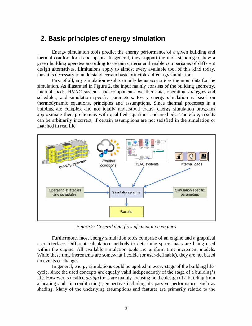
First of all, any simulation result can only be as accurate as the input data for the simulation. As illustrated in Figure 2, the input mainly consists of the building geometry, internal loads, HVAC systems and components, weather data, operating strategies and schedules, and simulation specific parameters. Every energy simulation is based on thermodynamic equations, principles and assumptions. Since thermal processes in a building are complex and not totally understood today, energy simulation programs approximate their predictions with qualified equations and methods. Therefore, results can be arbitrarily incorrect, if certain assumptions are not satisfied in the simulation or matched in real life.
Figure 2: General data flow of simulation engines
Furthermore, most energy simulation tools comprise of an engine and a graphical
user interface. Different calculation methods to determine space loads are being used within the engine. All available simulation tools are uniform time increment models. While these time increments are somewhat flexible (or user-definable), they are not based on events or changes.
In general, energy simulations could be applied in every stage of the building life-cycle, since the used concepts are equally valid independently of the stage of a building’s life. However, so-called design tools are mainly focusing on the design of a building from a heating and air conditioning perspective including its passive performance, such as shading. Many of the underlying assumptions and features are primarily related to the
3
design stage and limit capabilities for other stages of the life-cycle. In particular design tools are used to size HVAC equipment for worst case conditions and do not consider the overall annual performance. In contrast, simulation tools use more generic concepts, thus they can be used during any life-cycle phase. The latter produce more data (typically over a period of one year) that can be compared to actual building performance and, thus, they are also useful for commissioning and operations purposes.
Today, energy performance simulation tools are mainly based on one-dimensional heat transfer between thermal zones. This assumption simplifies the geometric input dramatically and allows shorter simulation run times. While 2 or 3 dimensional heat transfer would increase the accuracy of simulation results, geometry input and simulation run time is likely to be more complex. An extension to the DOE-2 model to accommodate two-dimensional heat transfer has been developed and is discussed in more detail in Section 3.1.3.
2.1. Input to energy simulation
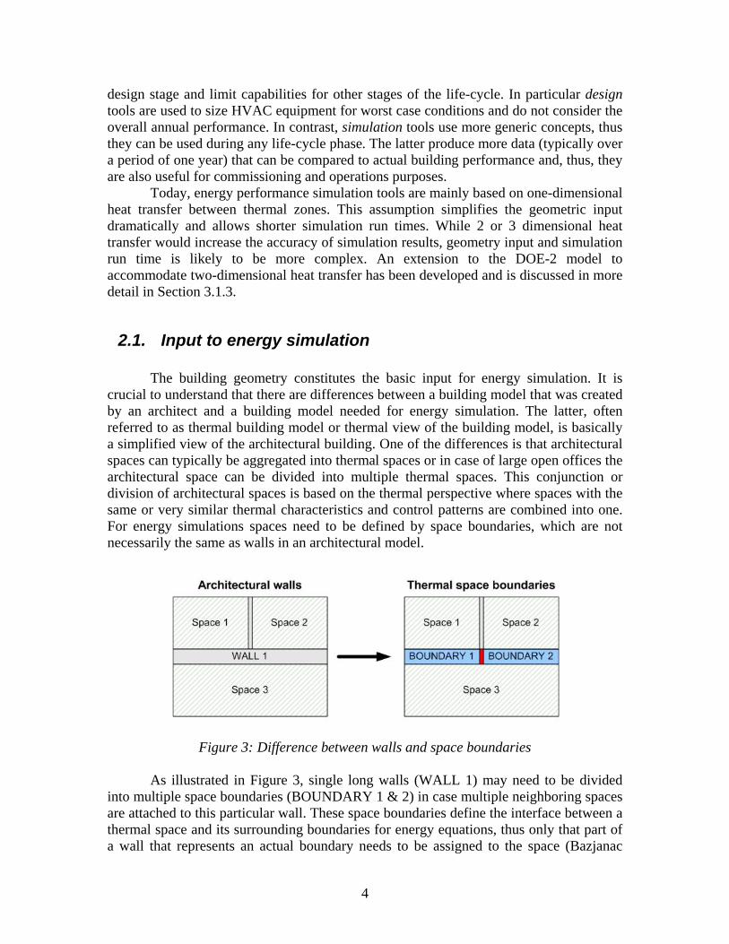
The building geometry constitutes the basic input for energy simulation. It is crucial to understand that there are differences between a building model that was created by an architect and a building model needed for energy simulation. The latter, often referred to as thermal building model or thermal view of the building model, is basically a simplified view of the architectural building. One of the differences is that architectural spaces can typically be aggregated into thermal spaces or in case of large open offices the architectural space can be divided into multiple thermal spaces. This conjunction or division of architectural spaces is based on the thermal perspective where spaces with the same or very similar thermal characteristics and control patterns are combined into one. For energy simulations spaces need to be defined by space boundaries, which are not necessarily the same as walls in an architectural model.
Figure 3: Difference between walls and space boundaries
As illustrated in Figure 3, single long walls (WALL 1) may need to be divided
into multiple space boundaries (BOUNDARY 1 & 2) in case multiple neighboring spaces are attached to this particular wall. These space boundaries define the interface between a thermal space and its surrounding boundaries for energy equations, thus only that part of a wall that represents an actual boundary needs to be assigned to the space (Bazjanac
4
2002). Based on this space boundary concept the intersecting portion of the two walls (illustrated in red) is ignored in the thermal simulation model, because of the mentioned one-dimensional heat transfer assumption. This intersection can only be described if two-dimensional heat transfer is available.
Freestanding walls or columns can be mostly ignored in thermal models. Since there is no difference in temperature between the exterior surfaces that all belong to the same thermal space there will be no heat transfer. However, in simulation cases where the thermal mass of these walls and columns may have an effect on simulation results, one can represent these with appropriate thermal mass objects that do not have a specific geometric representation, but contain the exposed surface area. None of the described engines takes freestanding walls or columns as part of the daylighting calculation into account. Thus modeling the columns or freestanding walls as internal walls does not improve the simulation results when compared to simple thermal mass objects.
Slabs and walls that do not relate to a particular building space and are external can be ignored from a heat transfer perspective, but need to be converted into shading objects if they shade the building. Shading devices are an important part of any energy model, since they can dramatically reduce solar loads in a space.
Today, curved surfaces can not be represented as such in any thermal simulation engine that is based on one-dimensional heat transfer. Usually objects with curved surfaces are approximated through a number of plane surfaces.
While in the early design phases both the architectural and the thermal model can sometimes be almost identical, the differences increase while design progresses. The automated simplification process to derive the input geometry for thermal simulation from an architectural model is still a challenge today, as discussed later in this paper. In practice, CAD models must be validated to ensure a sufficient geometric representation. This validation is either done visually or by model checker software, such as Solibri Model Checker (Solibri 2007), and by iteratively exporting and importing building geometry from CAD to thermal simulation tools, and correcting detected problems or inconsistencies.
Internal and external loads are necessary to provide enough information for an energy balance in a space. The external loads are strongly influenced by weather and climate, thus collected and statistically assembled weather data are used in energy performance simulation. Weather data files are being created for design purposes for an increasing number of cities and regions around the world. These weather files do not reflect a specific year, but provide statistical reference for the typical weather parameters of a specific location. During commissioning and operation weather information can sometimes be measured directly at the building in question or at weather stations that are locally close. Internal loads such as loads from people, lights and equipment in a space depend greatly on the actual usage of a space and the behavior of the occupants. It is obvious that assumptions have to be made about the quantity of internal loads in a given space for energy simulation in design.
HVAC systems and their components are a major part of the input information for thermal simulation models. These systems can be modeled to reflect the actual system if the energy simulation tool (graphical user interface and the engine) provides enough flexibility. To define a realistic representation of the real HVAC system within a predefined structure can sometimes be challenging. Therefore, newer engines such as
5
EnergyPlus support component-based HVAC modeling without the restriction of hard-coded predefined HVAC systems employed by older tools, such as DOE-2. Another important aspect is the possibility to model new HVAC technologies and concepts such as under-floor heating and cooling within the energy simulation tool. Besides the HVAC system configuration and HVAC component parameters, control strategies are necessary as input for energy simulations. These strategies define the simulated behavior of the HVAC components to act as a system and serve the building as intended. These control strategies in current simulation tools are simplistic when compared to actual control implementations.
Last but not least, every energy simulation tool needs specific simulation parameters, for example numeric convergence tolerances, that are needed for the underlying simulation model of the engine. These parameters influence the numerical behavior of the simulation engine. Also, the definition of parameters such as the simulated time frame and the time step (if applicable) has to be provided.
2.2. Assumptions in energy simulation
As mentioned earlier, the input, especially weather data and internal loads, for energy simulation is already based on assumptions, as are the thermodynamic concepts. For that matter, any simulation is based on assumptions, so that complex interrelations can be simplified and managed. Users need to be aware of these assumptions and be able to decide whether they are reasonable for their specific simulation or not. For example, the majority of energy simulation tools are based on the assumption that every space in a building is well-mixed. In other words, the temperature within a space is spatially uniform. This assumption applies for a majority of one story high spaces; but becomes less acceptable as the space height increases. Atria, for instance, extend over several floors; therefore, the temperature distribution in atria varies according to the height of the space.
Many energy simulation programs use simplified approaches for infiltration and natural ventilation that are pressure independent. While the traditional approach to slightly pressurize a building is sufficient for conventional HVAC systems, it is not adequate for buildings which are primarily naturally ventilated.
2.3. Basic tool architecture Most building simulation tools consist of two different components, the engine
and the graphical user interface. While the simulation engine is usually developed by one or more academic and/or research institutions, the user interfaces are mostly implemented by private software vendors.
6

Figure 4: General architecture of energy simulation tools
The general data flow principle between simulation engines and graphical user
interfaces is illustrated in Figure 4. The simulation engine uses an input file (or files) of a defined format that contains a representation of the previously described input. Based on this input the engine performs a simulation and writes its output into one or more output files. While the output files contain results from the simulation, they also contain information about the simulation run itself, such as warning messages or additional information to evaluate the input. Graphical user interfaces usually wrap around this process and enable the user an easier generation of input files, initiate the simulation with the engine and process the output files to illustrate results in a more graphical manner.
2.4. General purpose of energy simulation
A major benefit of energy simulation in design today is the comparison of architectural design alternatives: Alternatives to the original building design are validated for both thermal comfort and energy usage. For this type of application, the validity of the discussed assumptions is less crucial. Different design alternatives are based on almost exactly the same assumptions and the common belief is that relative differences in the simulation results are reliable. However, if building usage patterns are depended on the type of design alternative, the comparison of design alternatives may provide less accurate comparison results.
The prediction of absolute energy values of an energy simulation, given the assumptions, is rarely accurate. Usually, various validation tests, such as the BESTEST (Building Energy Simulation Test) that was developed and conducted by the International Energy Agency (IEA), are performed to validate building energy simulation tools relative to each other (IEA 2007). Validation tests comparing actual measurements from test buildings can also be conducted. The differences in absolute values are mainly due to
7
assumptions made regarding input information and the dynamic occupant usage of buildings. To obtain absolute predicted values that more closely match the actual values of the building, energy performance simulation models need to be calibrated with actual measurements. One of the biggest challenges for this comparison is the dynamic human behavior. Typically, internal loads resulting from humans are represented with schedules in energy simulation models; the actual usage of the building, however, changes on a daily basis. It is uncommon today to keep track of occupancy for every thermal zone, and to match the simulation input of occupancy with the actual occupancy. The input of static occupancy schedules in energy simulation can not properly represent the actual building usage. Statistically derived stochastic distributions may provide a methodology to simulate the actual behavior of people in buildings more accurately, but none of the energy simulation tools provide such a functionality.
2.5. Life-cycle usage Historically, energy simulation tools were developed to support building design to
enable comparisons of different design alternatives. Since all energy simulation tools are based on thermodynamic models that are valid in any phase of the building’s life, their usage is not limited to design only. Over the last several years tools have been developed or expanded to account for the specific needs of commissioning and operation of buildings. The major difference between these two kinds of tools is the level of detail. More detail is needed to validate the performance of HVAC components in a building during commissioning. Another difference is the modeling of the HVAC controls and strategies. Energy simulation tools such as DOE-2 implement idealized controls, which use predicted values of the simulation as input (eQUEST 2006). In reality, control mechanisms depend on sensors and control functions, which are reacting to sensor values. Therefore, typical control characteristics, such as the needed time to process signals are not simulated by the engine. Moreover, the set of control mechanisms available for simulation engines does not reflect the flexibility of control strategies in practice.
3. Thermal simulation engines
Due to the complexity of the energy predictions of a building, energy simulation tools usually consist of two parts. The engine contains all thermodynamic concepts in the form of equations and routines; user interfaces ease the input and display of results and account for different needs of users. In building design simulation engines are mainly used to support the design process of a building by comparing energy consumption of different design alternatives. This chapter describes both LBNL engines (DOE-2 and EnergyPlus), their brief history, functionality, life-cycle usage, interoperability concepts and major limitations.
Besides the two LBNL engines, several others are available today. While they are not a major focus in this paper, some are briefly described in the following sections. For a more detailed overview of available building simulation tools, refer to the Building
8
Energy Software Tools Directory (U.S. DOE 2007) and the paper on “contrasting the capabilities of building energy performance simulation” (Crawley et al. 2005).
3.1. DOE-2
The DOE-2.1E engine was developed by the Lawrence Berkeley National Laboratory and is one of the most widely used thermal simulation engines today. The engine was designed to study energy performance of the whole building during the design phase (Birdsall et al. 1990). The last official LBNL release of DOE-2.1E in 1994 included knowledge and expertise gained over a development process of 30 years. Due to its long presence on the market several user interfaces have been developed for DOE-2. Two user interfaces, RIUSKA and eQUEST, are described in Section 4 in this paper. Both user interfaces were selected for a review here due to their capability of data exchange with CAD applications. The following subchapters describe DOE-2’s major functionalities, its architecture, applicability during the life-cycle, interoperability, and limitations.
3.1.1. Tool architecture and functionality
The DOE-2 engine is able to simulate the thermal behavior of spaces in a building, where heat loads, such as solar gain, equipment loads, people loads, lighting loads, and air conditioning systems can be modeled and simulated with the engine. The geometry for the simulation needs to be fairly simplified from the real geometry of the building.
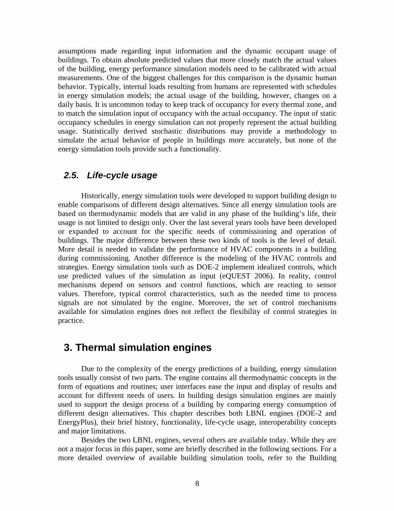
Figure 5: Dataflow of the DOE-2.1 engine (Birdsall et al. 1990)
9
Figure 5 illustrates the dataflow of the DOE-2.1 engine. The user input is combined with the materials, layers and construction library into the BDL input processor. The Building Description Language (BDL) processor transforms the input into a computer readable format that is later used by the four subprograms (simulation modules), LOADS, SYSTEMS, PLANT and ECONOMICS, which are executed sequentially. The LOADS subprogram uses this BDL description and weather data to perform heat loss and gain calculations based on assumed heating and cooling loads of related systems at a fixed space temperature at every time step. The second subprogram, SYSTEMS, uses gains and losses to determine additional heating or cooling needs for the space in question according to defined temperature set points. Next the PLANT subprogram calculates the fuel requirements of the HVAC components to accomplish the calculated performance of the systems. Finally, the ECONOMICS subprogram calculates the cost based on these fuel requirements and utility pricing structures (Birdsall et al. 1990).
DOE-2 first calculates loads in a space considering only external and internal loads. Based on the temperature difference between two adjacent spaces heat transfer is determined according to the so-called weight factor method which accounts for thermal mass. In the next step the resulting loads are used as input for the HVAC system calculations, and the simulation engine tries to satisfy space loads with the defined HVAC system, if possible. There is no feedback from the HVAC system calculation to the load calculation. As mentioned in the general simulation chapter, this process does not include feedback (data flow is only forward). This approach assumes that the loads in each space can be satisfied at every time step of the simulation. If loads can not be satisfied with the systems the temperature in the space changes and has an effect on further steps of the calculation. The air and water systems (as part of the SYSTEMS subprogram) can be modeled based on different predefined system definitions, which include some optional components or variations the user is able to select.
3.1.2. Space load calculation method
DOE-2 uses the so-called space weighting factor method to calculate heat transfer between spaces. Materials and constructions of walls are used to determine factors that describe heat transfer between spaces. After an initial load calculation of a space these factors are used to determine the actual heat transfer between the two spaces based on the temperature difference. They slow down the static heat balance between spaces to approximate the actual effect of building materials’ thermal mass on heat transfer. The weight factors are calculated prior to a simulation run to allow a faster simulation process. This weighting factor method is not based on thermodynamic equations and is one of the biggest assumptions within the DOE-2 engine.
10
3.1.3. Two-dimensional heat transfer extension
Bazjanac et al. developed a two-dimensional heat transfer extension to DOE-2. This extension specifically models the heat transfer of underground surfaces. It is based on a two-dimensional finite-difference model that was incorporated into a special version of DOE-2.1E. Two different approaches were evaluated throughout the study, one simplified and a more detailed truly two-dimensional approach. While the detailed two-dimensional model produced more accurate results the simulation run time increased by a factor of 30 to 40. As a consequence the simplified approach was integrated into DOE-2 to limit the increase in simulation time, but still provide an improvement in accuracy compared to the previous underground heat transfer model (Bazjanac et al. 2000).
This study shows that multi-dimensional heat transfer models are possible; however, there is a tradeoff between more accuracy and simulation runtime. Ideally the user would be able to decide if he wants to run a simplified and faster simulation model or use the more accurate and slower model depending on the focus of the analysis.
3.1.4. User-defined functions
User-defined functions were first introduced in DOE-2.1D and allow the modification of DOE-2 simulation parameters without the need to recompile the program (Winkelmann et al. 1993). Thus these functions provide more flexibility to the user to change variables, schedules and control strategies in a flexible manner. Simulation results need to be carefully reviewed to ensure that they provide the indented effect to the simulation model when user-defined functions are used. Only experience users should consider using these functions, since problems and errors can be introduced into the simulation. User-defined functions can be added only at predefined code entry points. Thus their use is limited to the availability of such entry points where the user wants to enhance the code with externally defined functions.
3.1.5. Life-cycle applicability
The DOE-2 engine was originally developed to be used during the design phase of a building. Its use during other life-cycle phases is possible, but has some shortcomings. Besides the limitations to model newer HVAC systems, DOE-2 has a significant shortcoming in its representation of controls. The detailed behavior of components can not be modeled, since controls are idealized. Thus they do not reflect practical issues, such as time delays or temperature set points that can not be met. In other words, the actual control mechanism consisting of the travel time of signals, the behavior of controls, and the movement and response of actuators is not included in the simulation. While this lack of detailed control representation does not effect comparisons of design alternatives, it becomes an important issue when comparing actual with simulated performance. Since DOE-2 has only a limited number of control strategies readily available to the user, uncommon control strategies can only be included into DOE-2 by
11
defining user-functions, which increase the simulation effort significantly and thus are seldom used in practice. For a detailed and thorough performance comparisons during commissioning or operation these shortcomings make it difficult to match predicted and observed performance metrics.
3.1.6. Data exchange and interoperability
The DOE-2 engine itself does not provide any data import or exchange with other applications, such as importing building geometry from CAD software. However, two DOE-2 user interfaces (RIUSKA and eQUEST) described in Section 4 provide data exchange functionalities, which are described in detail in that section. Geometry input for DOE-2 can be created by using the respective add-ons and the Green Building Studio webservice or by using RIUSKA’s IFC import functionality. The eQUEST tool can utilize this conversion process and import the resulting INP file. While this paper only demonstrates data exchange based on one example building, a more detailed study evaluated the Green Building Studio capabilities with various CAD tools and based on several test cases (Kolderup et al. 2006).
3.1.7. Limitations
There are several limitations of the DOE-2 engine. First of all, the missing feedback between the different modules is restricting the simulation results. Especially space conditions are less accurate than for simulations with feedback and, therefore, the resulting thermal comfort simulation and energy usage cannot be very accurate. Another limitation is the already mentioned assumption of well-mixed space temperatures. Furthermore, the 30 year old software product is expensive to support and hides possible errors in its code that are hard to determine and resolve. Adding more functionality, such as new components, is cumbersome when compared to component-based engines like EnergyPlus. The DOE-2 engine lacks the ability to truly model several newer HVAC concepts, such as under-floor air distribution (Cho and Haberl 2006). Since the DOE-2 space model is based on the uniform temperature assumption, HVAC systems that make use of stratification cannot be adequately represented. It is not possible to create a system based on an arbitrary combination of components, which is limiting the possibilities of air and water systems that can be evaluated and compared. In practice the limited number of system types results in the modeling of non-predefined HVAC systems by “shoeing” the actual HVAC system into a predefined system definitions as closely as possible. This modeling approach always results in approximation and may yield inadequate simulation results, depending on the HVAC system types and the experience of the user. DOE-2 offers possibilities for users to add case specific functions. Since this process involves a significant effort and requires understanding of DOE-2, only experienced users are able to use these functions to increase the accuracy of the simulation model. The limited amount of code entry points in the DOE-2 model restrict users significantly in their ability to model a reasonable representation of the actual HVAC system.
12
3.2. EnergyPlus
EnergyPlus (Version 2.1) uses the best features of the two energy simulation engines DOE-2 and BLAST, resulting in a so-called “new generation” simulation engine. The Building Loads Analysis and System Thermodynamics (BLAST) system is an aggregation of programs to predict energy consumption and energy system performance and cost in buildings (BLAST 2003). BLAST’s heat balance method is based on actual thermodynamic equations and produces better results than its counterpart in DOE-2 (weighted heat balance method). EnergyPlus development is lead by LBNL and also includes the U.S. Army Construction Engineering Research Laboratory (CERL), the University of Illinois (UI), Oklahoma State University (OSU), GARD Analytics, Florida Solar Energy Center, and the U.S. Department of Energy (DOE) (Crawley et al. 2002). Its latest version V2.0 includes links to the multi-zone air flow engine COMIS (COMIS 2003) and SPARK. COMIS is a nodal air flow and containment distribution engine that enables the integration of air flow in EnergyPlus simulation as occurring in naturally ventilated buildings. The Simulation Problem Analysis and Research Kernel, SPARK, is a software tool to solve simulation problems in general, not only specifically for energy simulations (LBNL 2003). SPARK “allows the user to build simulation models of complex physical processes by connecting equation-based calculation modules from an object library” (U.S. DOE 2007). Its link to EnergyPlus enables the creation of user defined HVAC components based on SPARK’s object library.
3.2.1. Tool architecture and functionality
EnergyPlus is based on an integrated (loads and systems simulation) approach (Crawley et al. 2002), which leads to more accurate predictions of temperatures in spaces and therefore a better estimate of various resulting parameters, such as thermal comfort. The load calculations are based on AHSRAE’s preferred heat-balanced-based approach (Strand et al. 2001). EnergyPlus also contains inter-zonal airflow, moisture absorption and desorption, definitions of more realistic HVAC system controls and radiant heating and cooling systems. In addition, EnergyPlus enables automated sizing of many component-specific parameters. In summary, results are more accurate and reliable than with DOE-2 for most of the simulated buildings and systems.
Today, an EnergyPlus simulation is mainly based on input from text files, which increases the effort to define all necessary input data compared to engines with graphical user interfaces. Several user interfaces are under development and some can be tested as beta versions. For a complete list of user interfaces for EnergyPlus refer to the EnergyPlus webpage (LBNL 2007). The most advanced user interface, DesignBuilder, is described in Section 4.3. Two IFC interfaces which enable data exchange between EnergyPlus and other applications are illustrated in Sections 4.4 and 4.5.
Figure 6 shows the data flow within and around the EnergyPlus engine. The heat and thermal mass balance simulation is integrated with the building systems simulation, such that the result is always accurate and independent of space loads being met or not. In addition, modules such as COMIS, SPARK, TRANSYS and others can easily be incorporated into the simulation to combine different concepts and aspects of building
13
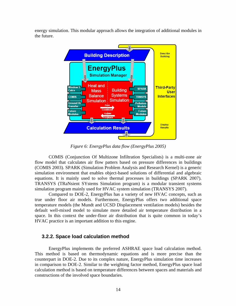
energy simulation. This modular approach allows the integration of additional modules in the future.
Figure 6: EnergyPlus data flow (EnergyPlus 2005)
COMIS (Conjunction Of Multizone Infiltration Specialists) is a multi-zone air
flow model that calculates air flow patters based on pressure differences in buildings (COMIS 2003). SPARK (Simulation Problem Analysis and Research Kernel) is a generic simulation environment that enables object-based solutions of differential and algebraic equations. It is mainly used to solve thermal processes in buildings (SPARK 2007). TRANSYS (TRaNsient SYstems Simulation program) is a modular transient systems simulation program mainly used for HVAC system simulation (TRANSYS 2007).
Compared to DOE-2, EnergyPlus has a variety of new HVAC concepts, such as true under floor air models. Furthermore, EnergyPlus offers two additional space temperature models (the Mundt and UCSD Displacement ventilation models) besides the default well-mixed model to simulate more detailed air temperature distribution in a space. In this context the under-floor air distribution that is quite common in today’s HVAC practice is an important addition to this engine.
3.2.2. Space load calculation method
EnergyPlus implements the preferred ASHRAE space load calculation method. This method is based on thermodynamic equations and is more precise than the counterpart in DOE-2. Due to its complex nature, EnergyPlus simulation time increases in comparison to DOE-2. Similar to the weighting factor method, EnergyPlus space load calculation method is based on temperature differences between spaces and materials and constructions of the involved space boundaries.
14
3.2.3. Life-cycle usage
EnergyPlus’ more accurate simulation concepts, the latest integration of SPARK and new efforts towards more detailed control strategies clearly enable the usage of EnergyPlus during all phases of the life-cycle of a building. The flexible component-based architecture allows a more precise representation of real HVAC systems than older simulation engines, especially in the modeling of newer HVAC. While EnergyPlus provides more flexible control mechanisms than DOE-2 and more control mechanisms are continuously added, the control representation can still not account for all strategies that are used in practice. Control functions in practice can basically use any kind of input that comes from sensors and process it based on predefined equations. As a result actuators’ positions are changed to accommodate the changed conditions in the building. EnergyPlus has a variety of control objects, which implement the most common control strategies, but it does not explicitly model the actual control process that consists of sensors gathering data, controllers processing sensed information and manipulating actuators. The main challenges to provide more flexible control strategies or even allow the use of the actual control code in EnergyPlus is the lack of any industry standard for it. Every control manufacturer has it own control code language that makes it difficult to provide a simple interface that could communicate with all the different control languages. However, a recent project at LBNL successfully linked the EnergyPlus simulation with control hardware to realize a real-time simulation. While EnergyPlus simulates the behavior of the building, the controller uses EnergyPlus results as simulated input for the control strategy and feeds the control answer back to EnergyPlus. EnergyPlus uses the updated control signal and performs a simulation of the next time step (Xu et al. 2004). This illustrates a unique opportunity to debug and improve the control strategy, but due to the actual need of controller hardware it is not a practical procedure for everyday simulation.
The idealized simulation of HVAC components poses another issue when trying to model the real building situation. EnergyPlus assumes that HVAC components function at idealized conditions, thus it does not account for faulty or slowly decreasing performance of HVAC components. While it is obvious that over time the functioning of HVAC components changes due to soiling, corrosion, and other influences that decrease the performance of HVAC equipment, EnergyPlus does not take such performance changes into account. Thus the comparison between observed and predicted energy performance becomes more difficult to make as the building ages.
In summary, EnergyPlus provides the flexibility and functionality to be used over all stages of a building life-cycle with some limitations during building operation because of simplified control strategies and idealized HVAC components.
3.2.4. Interoperability
Two IFC interfaces, the GST (Geometry Simplification Tool) tool in combination with the IDF Generator and the IFC HVAC Interface to EnergyPlus, which are described in detail in Sections 4.4 and 4.5, enable limited interoperability for EnergyPlus. IFC is an international data exchange standard for building information developed by the
15
International Alliance for Interoperability (IAI). The IAI adopted the IFC file format from ISO (STEP Part 21) to represent an object-oriented building description across all disciplines and life-cycle phases of a building (IAI 2007). So far the IAI has focused its IFC development efforts mostly on the architectural representation of a building (so called “coordination view”), but other domains, such as the HVAC domain, have been defined or are under development.
The IFC standard can also be described as a Building Information Model (BIM) representation and exchange format. The main purpose of a BIM is to store and allow access to data about a building project over all phases of the building’s life across all disciplines. Software applications can read and/or write data from/to a BIM that can be reused by other applications and, thus, exchange building information without redundancy and loss of fidelity.
3.2.5. Limitations
Today the most restricting limitation of EnergyPlus is the missing graphical user interface that provides all EnergyPlus capabilities. Besides the DesignBuilder, which is described in Section 4.3, there are several other GUIs under development (U.S. DOE 2007). A complete, simple but flexible user interface is needed to allow faster and more convenient user input.
Although EnergyPlus includes a variety of links to other simulation engines (COMIS, SPARK) several limitations apply to the usage of these links. For example, the coupling of detailed airflow analysis (COMIS) with energy simulation is only reliable for non-pressurized HVAC systems. The earlier mentioned simplified control representation and idealized HVAC components are further limitations of EnergyPlus today.
4. User interfaces
All user interfaces that are described in this section have one goal in common: to enable easier and, therefore, faster input and output of data for the described energy simulation engines. Nevertheless, these interfaces vary in their design and purpose of use.
4.1. RIUSKA
The RIUSKA development by Olof Granlund Oy started in 1996. From the beginning one of its main goals was to develop a tool that can be used during all phases of the life-cycle and to realize reuse of data (Jokela et al. 1997). RIUSKA (Version 4.4.7) is based on the DOE-2.1E engine and has an IFC interface through the BSPro server middleware. The BSPro server (Granlund 2007a), also developed by Granlund, automatically simplifies complex geometric information contained in the IFC model for the needs of thermal simulation.
16
4.1.1. Tool architecture and functionality
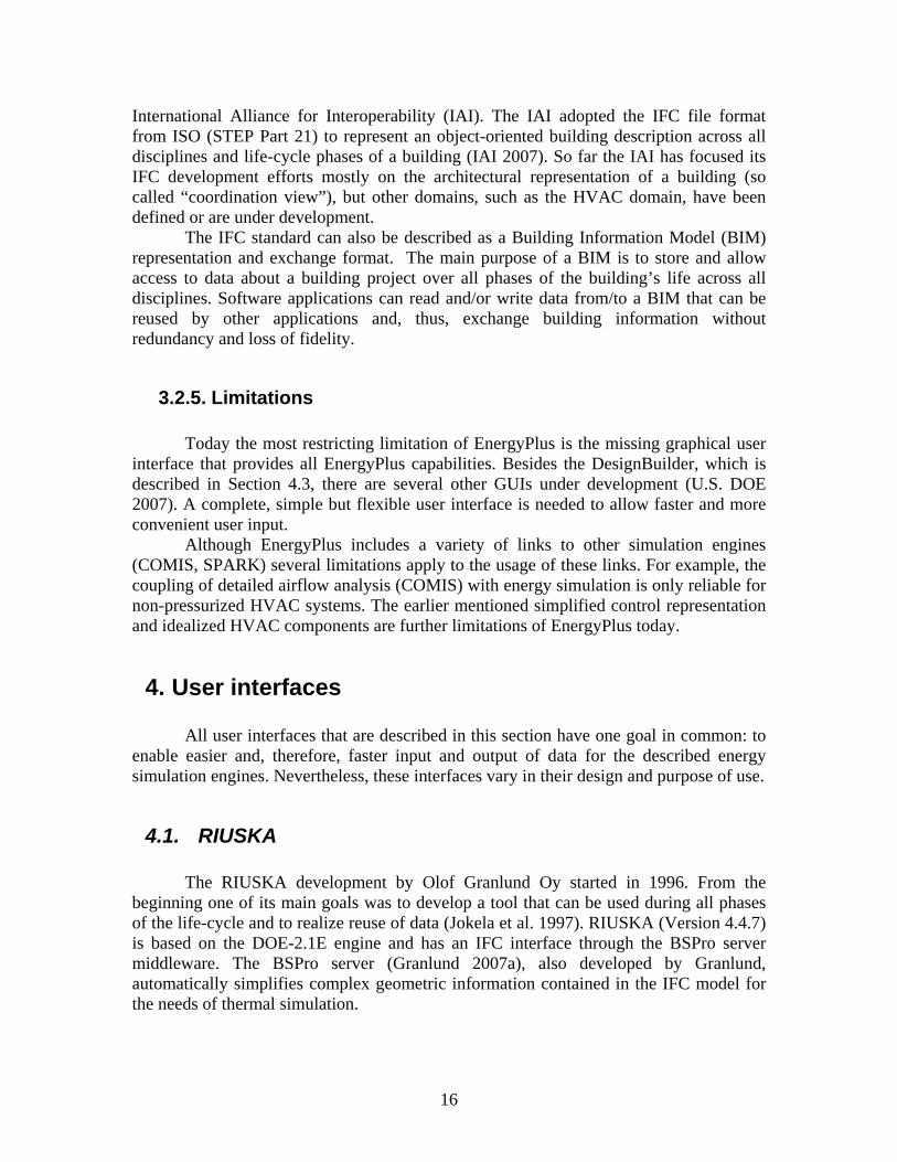
RIUSKA is based on the import of building geometry through IFC. In addition to the imported geometry the user needs to specify the location, space types, allocating spaces into thermal zones and defining air conditioning system parameters in order to run a simulation. The basic workflow is illustrated in Figure 7.
Figure 7: Basic workflow of a RIUSKA simulation
The first step of the RIUSKA workflow is the selection of locations, where a
weather file (BIN file) is available as needed as input for the DOE-2 engine. The next step is the simplification of IFC geometry by the BSPro server middleware and its import into RIUSKA. In addition to the basic workflow, existing geometric components can be modified, if needed, and construction type (layers, material type and thickness) assignments to geometric component types can be changed. The construction types are predefined types in the RIUSKA database. Currently this construction type information is not part of the transfer from CAD to energy simulation tools via IFC. However, it is important to identify construction types in CAD (e.g. different types of walls), so that proper construction definitions can be assigned more easily in RISUKA. After the geometry has been sufficiently defined, space types are assigned to spaces. These space types include predefined parameters for a space, such as temperature set points or internal loads. Thermal space parameters are predefined in the RIUSKA database and are based on energy codes and user experience. If needed, these values can be modified to reflect the current building project needs. The next step is the assignment of spaces into thermal
17
zones. Each thermal zone is served by one air system, whose type definition follows next. At this point all basic parameters have been defined and more detailed parameters can be changed from their default values to project-specific values. The workflow facilitates multiple iterations to compare different configurations of the input. RIUSKA supports different design alternatives through so-called “cases”. The user can create alternatives based on the base case and evaluate the effect of different model configurations. After the creation of an alternative, this alternative is decoupled from the base case, so that changes to the base case are not automatically reflected in the alternatives.
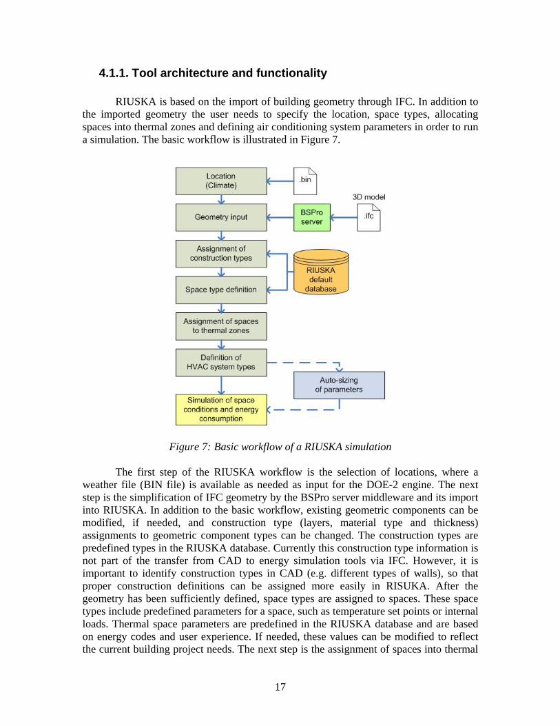
RIUSKA provides four different AC systems: constant volume, variable volume, cooled beam and induction unit. All four are based on an air loop system, as illustrated in Figure 8, and definition of HVAC equipment at the space level. Each air loop consists of a supply and return fan, a cooling and heating coil, a heat recovery unit and a supply temperature set point. This basic concept can only be changed by subtracting components and modifying basic parameters. The definition of specific space HVAC equipment depends on the system type and can include a radiator, an induction unit, and a cooled beam.
Figure 8: Basis HVAC system configuration in RIUSKA
For three of the HVAC systems one parameter can be automatically sized by
RIUSKA. The maximum air flow rate of variable air systems is sizable for the variable air system. For the cooled beam and induction unit system the sizeable parameter is the space cooling power. The auto sizing functionality is accomplished by multiple DOE-2 engine runs.
4.1.2. Life-cycle usage
According to Jokela et al. (1997) RIUSKA can be used during the complete life-cycle of a building. From early design phases to final design the definition of the simulation model gains detail. Currently, Granlund’s facility management software “Taloinfo” is based on RIUSKA simulations to compare predicted with measured building parameters (Kuoppala 2003). As discussed earlier, the limitation of a DOE-2 based simulation during facility operation apply here, such that the comparisons between predicted and observed performance can only be done meaningfully at the building and HVAC system levels. More detailed comparisons on an HVAC component level are rather difficult, due to the built-in limitations of predefined HVAC systems. Comparisons
18
on the building or system level could help to identify major differences between measurements and simulation results. RIUSKA itself does not provide any functionality that enables input of measured data or comparison of measurements and predictions, however; Taloinfo provides a web-based interface to visually compare measurements with results from RIUSKA simulations.
4.1.3. Interoperability
RIUSKA is certified as IFC compliant (for IFC versions 1.5.1, 2.0, and 2x) through Granlund’s BSPro server (Granlund 2007a). Starting with the IFC2x2 certification process, software programs are certified as IFC compliant if they pass a two stage certification process. In the first stage, a set of IFC files exported by the program in question; in the second stage a pilot project that involves end-users is tested. If both are successful the software program is IFC certified (IAI 2007).
The current RIUSKA version can import building geometry in the format of all major IFC versions. Furthermore, six characteristic thermal parameters for each space (design heating and cooling set point temperatures, heat gain and heat loss, supply and return airflow rates) can be written to the IFC file and be used by downstream applications. MagiCAD Room, for example, provides the functionality to import these values in support of HVAC ducting design (Progman 2007).
Limitations of the IFC import originate in the building story-based structure of RIUSKA. As illustrated in Figure 9, the geometry is mostly imported correctly. RIUSKA ignores slabs in the IFC file and the 3D view (see area marked I in Fig. 9), and simply generates them internally according to the size of the space defined by the bounding walls. This strategy avoids many problems that can occur when slabs are part of complex building geometry, as illustrated with eQUEST (see section 4.2.3). The floor-based concept, however, restricts the application to simple building geometry. For example, sloped roofs need additional manipulation within RIUSKA. The best import results are achieved when RIUSKA is used in conjunction with Granlund’s own CAD software SMOG (Granlund 2007b), which is also building story-based. Problems can occur if CAD models are imported from other CAD applications. For example, RIUSKA does not currently support two spaces within one building story that are on top of each other. For buildings with plenums this is quite a typical condition. Spaces that span over two floors can be problematic, too. Single story walls between single story spaces and spaces that span over multiple floors are assigned the incorrect wall type (internal instead of external – see area marked II in Fig. 9). Although the wall type can be easily corrected in RIUSKA, errors must first be detected by the user, not always an easy or obvious task.
19
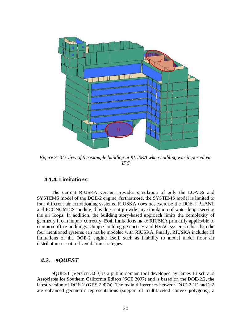
Figure 9: 3D-view of the example building in RIUSKA when building was imported via
IFC
4.1.4. Limitations
The current RIUSKA version provides simulation of only the LOADS and SYSTEMS model of the DOE-2 engine; furthermore, the SYSTEMS model is limited to four different air conditioning systems. RIUSKA does not exercise the DOE-2 PLANT and ECONOMICS module, thus does not provide any simulation of water loops serving the air loops. In addition, the building story-based approach limits the complexity of geometry it can import correctly. Both limitations make RIUSKA primarily applicable to common office buildings. Unique building geometries and HVAC systems other than the four mentioned systems can not be modeled with RIUSKA. Finally, RIUSKA includes all limitations of the DOE-2 engine itself, such as inability to model under floor air distribution or natural ventilation strategies.
4.2. eQUEST
eQUEST (Version 3.60) is a public domain tool developed by James Hirsch and Associates for Southern California Edison (SCE 2007) and is based on the DOE-2.2, the latest version of DOE-2 (GBS 2007a). The main differences between DOE-2.1E and 2.2 are enhanced geometric representations (support of multifaceted convex polygons), a
20
newly developed HVAC system concept, and additional HVAC components and features (SRG et al. 1998). This free energy simulation tool enables all functionalities of the DOE-2.2 simulation engine and supports conformance analyses with Title 24 California energy code (California Energy Commission 2006). The following sections describe eQUEST in more detail according to the relevant issues in this paper.
4.2.1. Tool architecture and functionality
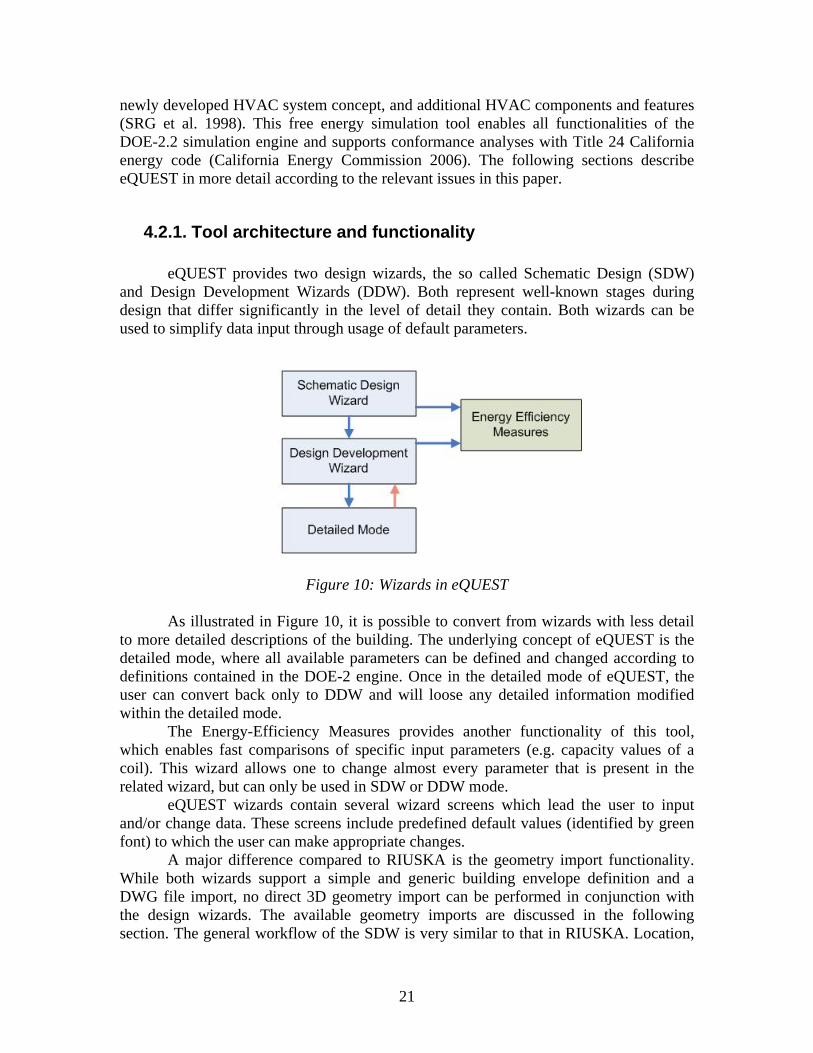
eQUEST provides two design wizards, the so called Schematic Design (SDW) and Design Development Wizards (DDW). Both represent well-known stages during design that differ significantly in the level of detail they contain. Both wizards can be used to simplify data input through usage of default parameters.
Figure 10: Wizards in eQUEST
As illustrated in Figure 10, it is possible to convert from wizards with less detail
to more detailed descriptions of the building. The underlying concept of eQUEST is the detailed mode, where all available parameters can be defined and changed according to definitions contained in the DOE-2 engine. Once in the detailed mode of eQUEST, the user can convert back only to DDW and will loose any detailed information modified within the detailed mode.
The Energy-Efficiency Measures provides another functionality of this tool, which enables fast comparisons of specific input parameters (e.g. capacity values of a coil). This wizard allows one to change almost every parameter that is present in the related wizard, but can only be used in SDW or DDW mode.
eQUEST wizards contain several wizard screens which lead the user to input and/or change data. These screens include predefined default values (identified by green font) to which the user can make appropriate changes.
A major difference compared to RIUSKA is the geometry import functionality. While both wizards support a simple and generic building envelope definition and a DWG file import, no direct 3D geometry import can be performed in conjunction with the design wizards. The available geometry imports are discussed in the following section. The general workflow of the SDW is very similar to that in RIUSKA. Location,
21
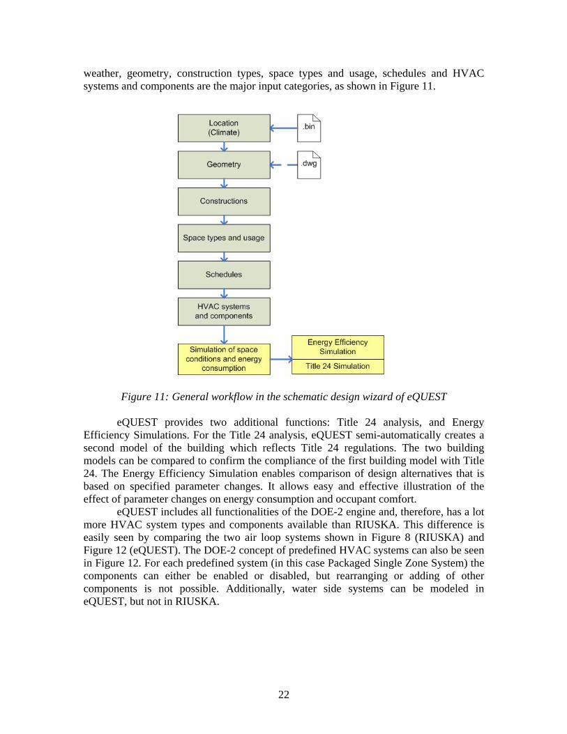
weather, geometry, construction types, space types and usage, schedules and HVAC systems and components are the major input categories, as shown in Figure 11.
Figure 11: General workflow in the schematic design wizard of eQUEST
eQUEST provides two additional functions: Title 24 analysis, and Energy
Efficiency Simulations. For the Title 24 analysis, eQUEST semi-automatically creates a second model of the building which reflects Title 24 regulations. The two building models can be compared to confirm the compliance of the first building model with Title 24. The Energy Efficiency Simulation enables comparison of design alternatives that is based on specified parameter changes. It allows easy and effective illustration of the effect of parameter changes on energy consumption and occupant comfort.
eQUEST includes all functionalities of the DOE-2 engine and, therefore, has a lot more HVAC system types and components available than RIUSKA. This difference is easily seen by comparing the two air loop systems shown in Figure 8 (RIUSKA) and Figure 12 (eQUEST). The DOE-2 concept of predefined HVAC systems can also be seen in Figure 12. For each predefined system (in this case Packaged Single Zone System) the components can either be enabled or disabled, but rearranging or adding of other components is not possible. Additionally, water side systems can be modeled in eQUEST, but not in RIUSKA.
22
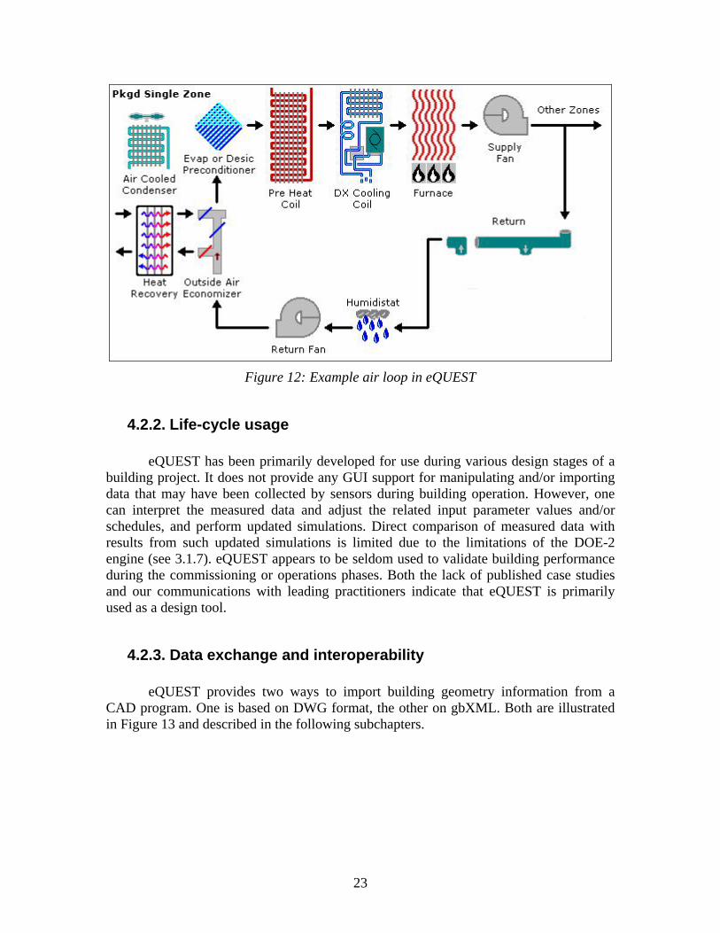
Figure 12: Example air loop in eQUEST
4.2.2. Life-cycle usage
eQUEST has been primarily developed for use during various design stages of a building project. It does not provide any GUI support for manipulating and/or importing data that may have been collected by sensors during building operation. However, one can interpret the measured data and adjust the related input parameter values and/or schedules, and perform updated simulations. Direct comparison of measured data with results from such updated simulations is limited due to the limitations of the DOE-2 engine (see 3.1.7). eQUEST appears to be seldom used to validate building performance during the commissioning or operations phases. Both the lack of published case studies and our communications with leading practitioners indicate that eQUEST is primarily used as a design tool.
4.2.3. Data exchange and interoperability
eQUEST provides two ways to import building geometry information from a CAD program. One is based on DWG format, the other on gbXML. Both are illustrated in Figure 13 and described in the following subchapters.
23
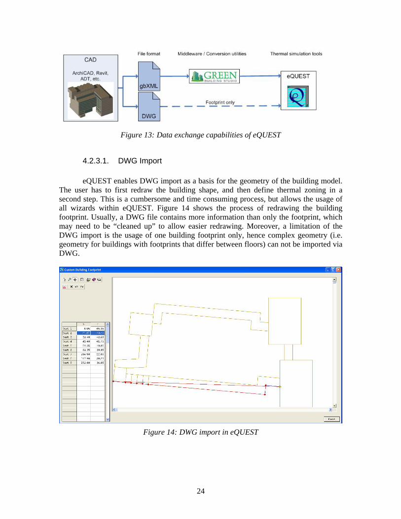
Figure 13: Data exchange capabilities of eQUEST
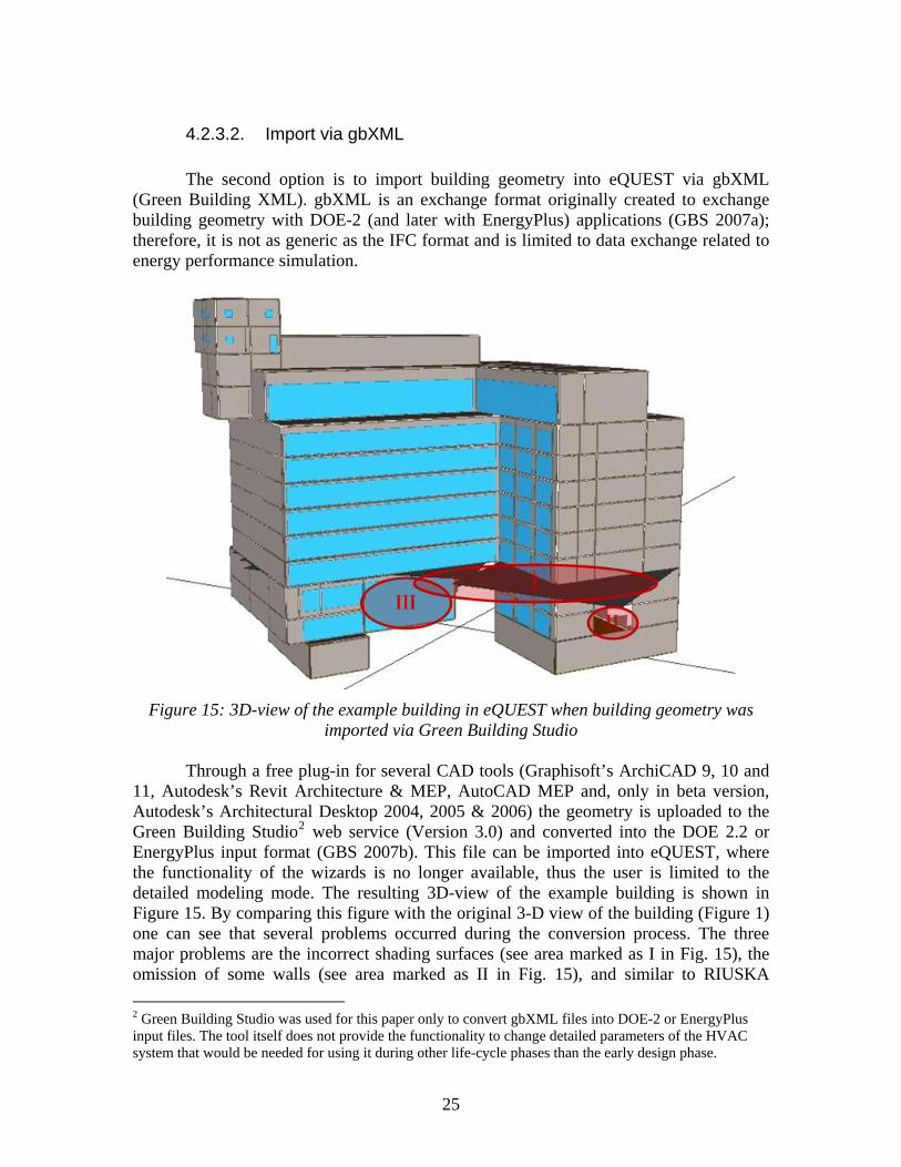
4.2.3.1. DWG Import
eQUEST enables DWG import as a basis for the geometry of the building model. The user has to first redraw the building shape, and then define thermal zoning in a second step. This is a cumbersome and time consuming process, but allows the usage of all wizards within eQUEST. Figure 14 shows the process of redrawing the building footprint. Usually, a DWG file contains more information than only the footprint, which may need to be “cleaned up” to allow easier redrawing. Moreover, a limitation of the DWG import is the usage of one building footprint only, hence complex geometry (i.e. geometry for buildings with footprints that differ between floors) can not be imported via DWG.
Figure 14: DWG import in eQUEST
24
4.2.3.2. Import via gbXML
The second option is to import building geometry into eQUEST via gbXML (Green Building XML). gbXML is an exchange format originally created to exchange building geometry with DOE-2 (and later with EnergyPlus) applications (GBS 2007a); therefore, it is not as generic as the IFC format and is limited to data exchange related to energy performance simulation.
Figure 15: 3D-view of the example building in eQUEST when building geometry was
imported via Green Building Studio
Through a free plug-in for several CAD tools (Graphisoft’s ArchiCAD 9, 10 and 11, Autodesk’s Revit Architecture & MEP, AutoCAD MEP and, only in beta version, Autodesk’s Architectural Desktop 2004, 2005 & 2006) the geometry is uploaded to the Green Building Studio2 web service (Version 3.0) and converted into the DOE 2.2 or EnergyPlus input format (GBS 2007b). This file can be imported into eQUEST, where the functionality of the wizards is no longer available, thus the user is limited to the detailed modeling mode. The resulting 3D-view of the example building is shown in Figure 15. By comparing this figure with the original 3-D view of the building (Figure 1) one can see that several problems occurred during the conversion process. The three major problems are the incorrect shading surfaces (see area marked as I in Fig. 15), the omission of some walls (see area marked as II in Fig. 15), and similar to RIUSKA 2 Green Building Studio was used for this paper only to convert gbXML files into DOE-2 or EnergyPlus input files. The tool itself does not provide the functionality to change detailed parameters of the HVAC system that would be needed for using it during other life-cycle phases than the early design phase.
25
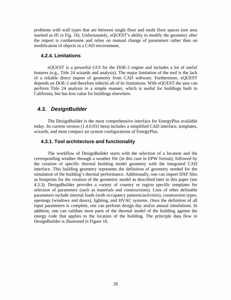
problems with wall types that are between single floor and multi floor spaces (see area marked as III in Fig. 16). Unfortunately, eQUEST’s ability to modify the geometry after the import is cumbersome and relies on manual change of parameters rather than on modification of objects in a CAD environment.
4.2.4. Limitations
eQUEST is a powerful GUI for the DOE-2 engine and includes a lot of useful features (e.g., Title 24 wizards and analysis). The major limitation of the tool is the lack of a reliable direct import of geometry from CAD software. Furthermore, eQUEST depends on DOE-2 and therefore inherits all of its limitations. With eQUEST the user can perform Title 24 analysis in a simple manner, which is useful for buildings built in California, but has less value for buildings elsewhere.
4.3. DesignBuilder The DesignBuilder is the most comprehensive interface for EnergyPlus available
today. Its current version (1.4.0.031 beta) includes a simplified CAD interface, templates, wizards, and most compact air system configurations of EnergyPlus.
4.3.1. Tool architecture and functionality
The workflow of DesignBuilder starts with the selection of a location and the corresponding weather through a weather file (in this case in EPW format), followed by the creation of specific thermal building model geometry with the integrated CAD interface. This building geometry represents the definition of geometry needed for the simulation of the building’s thermal performance. Additionally, one can import DXF files as footprints for the creation of the geometric model as described later in this paper (see 4.3.3). DesignBuilder provides a variety of country or region specific templates for selection of parameters (such as materials and constructions). Lists of other definable parameters include internal loads (with occupancy patterns/activities), construction types, openings (windows and doors), lighting, and HVAC systems. Once the definition of all input parameters is complete, one can perform design day and/or annual simulations. In addition, one can validate most parts of the thermal model of the building against the energy code that applies to the location of the building. The principle data flow in DesignBuilder is illustrated in Figure 16.
26
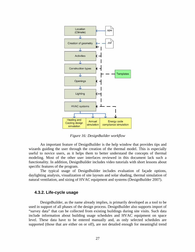
Figure 16: DesignBuilder workflow
An important feature of DesignBuilder is the help window that provides tips and
wizards guiding the user through the creation of the thermal model. This is especially useful to novice users, as it helps them to better understand the concepts of thermal modeling. Most of the other user interfaces reviewed in this document lack such a functionality. In addition, DesignBuilder includes video tutorials with short lessons about specific features of the program.
The typical usage of DesignBuilder includes evaluation of façade options, daylighting analysis, visualization of site layouts and solar shading, thermal simulation of natural ventilation, and sizing of HVAC equipment and systems (DesignBuilder 2007).
4.3.2. Life-cycle usage
DesignBuilder, as the name already implies, is primarily developed as a tool to be used in support of all phases of the design process. DesignBuilder also supports import of “survey data” that can be collected from existing buildings during site visits. Such data include information about building usage schedules and HVAC equipment on space level. These data have to be entered manually and, as only selected schedules are supported (those that are either on or off), are not detailed enough for meaningful trend
27
analysis. Thus trends for data that change values dynamically can not be defined through “survey data” collection. DesignBuilder only supports compact HVAC system definitions and is not yet able to make use of detailed component-based definitions. Its ability to describe an actual building HVAC system is thus limited, as is its use in the commissioning and operations phases of the building life-cycle.
4.3.3. Data exchange and interoperability
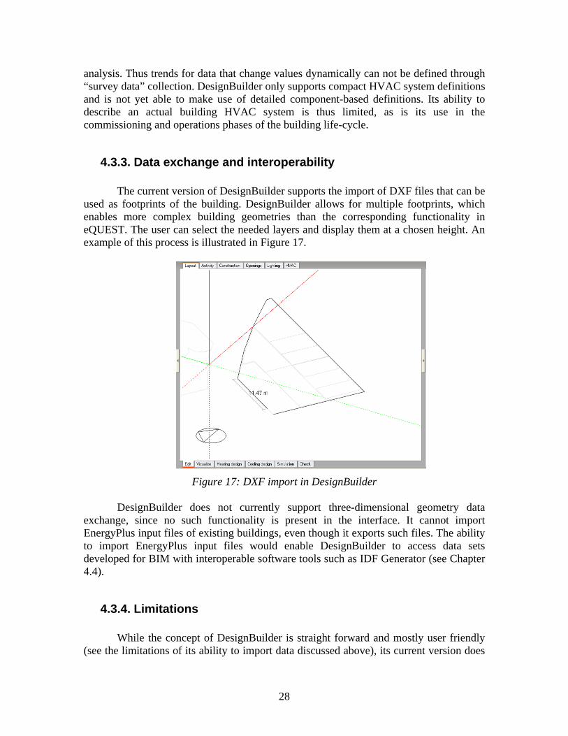
The current version of DesignBuilder supports the import of DXF files that can be used as footprints of the building. DesignBuilder allows for multiple footprints, which enables more complex building geometries than the corresponding functionality in eQUEST. The user can select the needed layers and display them at a chosen height. An example of this process is illustrated in Figure 17.
Figure 17: DXF import in DesignBuilder
DesignBuilder does not currently support three-dimensional geometry data
exchange, since no such functionality is present in the interface. It cannot import EnergyPlus input files of existing buildings, even though it exports such files. The ability to import EnergyPlus input files would enable DesignBuilder to access data sets developed for BIM with interoperable software tools such as IDF Generator (see Chapter 4.4).
4.3.4. Limitations
While the concept of DesignBuilder is straight forward and mostly user friendly (see the limitations of its ability to import data discussed above), its current version does
28
not fully support all functionalities of EnergyPlus. It mainly implements “compact” HVAC definitions that provide simple and compact definitions of HVAC systems, but do not include detailed information about the components and their topology. The component-based definitions are one of the major strengths of EnergyPlus, because they provide the user with flexibility in modeling. The inability to import EnergyPlus input files (discussed above) limits the utility of the program and forces the user to recreate a 3D geometry model for energy analysis.
4.4. IDF Generator
The IDF Generator, a new tool in development by LBNL, works in conjunction with the Geometry Simplification Tool (GST). The latter tool is jointly developed by Graphisoft and LBNL. Its current version (a pre alpha release) is still being tested.
GST simplifies the original building geometry defined in IFC format and converts it into gbXML format. The original building geometry is defined by the architect; GST performs the simplification automatically (i.e. without user intervention) according to the built-in rules of data transformation. Thus GST provides a crucial service in converting the geometry of the architects’ view of the building into the geometry of the thermal view of the same building. The built-in data transformation rules assure that, given the same original building geometry (defined in the IFC file), the simplified building geometry imported into EnergyPlus (and into any other simulation tool capable of importing data from GST) will be correct and the same in every repeated instance (Bazjanac and Kiviniemi 2007). Additional rules, planned for future versions, will enable automatic extension of building construction definitions (that originate in model based CAD tools) with associated thermodynamic properties, automatic definition of exterior shading components’ geometry, and the definition of embedded and free-standing columns. Embedded columns will be treated as wall objects; the user will be able to specify when to ignore the free-standing columns, when to add their volume to the thermal mass of the building, or when to convert them into wall objects with the corresponding geometry.
The IDF generator (currently an early prototype) provides a simple user interface to run GST, and converts the data in the gbXML file into EnergyPlus Input Data Format (IDF). The resulting IDF file contains all information related to building geometry and constructions needed to run an EnergyPlus simulation. The IDF file does not include any HVAC definitions - these are the focus of a separate interface, the IFC HVAC Interface to EnergyPlus.
4.5. IFC HVAC Interface to EnergyPlus
EnergyPlus can also exchange HVAC data through its IFC HVAC Interface. This interface is the first IFC HVAC interface capable of reading and writing complete HVAC systems from and to an IFC file (Bazjanac and Maile 2003). The data flow of both IFC Interfaces to EnergyPlus is shown in Figure 18. The IFC HVAC Interface enables conversion of HVAC information from IFC to EnergyPlus format and vise versa. All information EnergyPlus uses to define HVAC systems is covered by the interface. Its
29
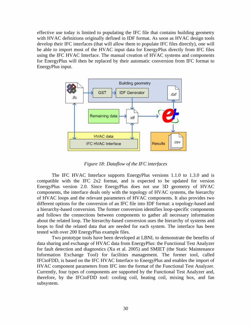
effective use today is limited to populating the IFC file that contains building geometry with HVAC definitions originally defined in IDF format. As soon as HVAC design tools develop their IFC interfaces (that will allow them to populate IFC files directly), one will be able to import most of the HVAC input data for EnergyPlus directly from IFC files using the IFC HVAC Interface. The manual creation of HVAC systems and components for EnergyPlus will then be replaced by their automatic conversion from IFC format to EnergyPlus input.
Figure 18: Dataflow of the IFC interfaces
The IFC HVAC Interface supports EnergyPlus versions 1.1.0 to 1.3.0 and is
compatible with the IFC 2x2 format, and is expected to be updated for version EnergyPlus version 2.0. Since EnergyPlus does not use 3D geometry of HVAC components, the interface deals only with the topology of HVAC systems, the hierarchy of HVAC loops and the relevant parameters of HVAC components. It also provides two different options for the conversion of an IFC file into IDF format: a topology-based and a hierarchy-based conversion. The former conversion identifies loop-specific components and follows the connections between components to gather all necessary information about the related loop. The hierarchy-based conversion uses the hierarchy of systems and loops to find the related data that are needed for each system. The interface has been tested with over 200 EnergyPlus example files.
Two prototype tools have been developed at LBNL to demonstrate the benefits of data sharing and exchange of HVAC data from EnergyPlus: the Functional Test Analyzer for fault detection and diagnostics (Xu et al. 2005) and SMIET (the Static Maintenance Information Exchange Tool) for facilities management. The former tool, called IFCtoFDD, is based on the IFC HVAC Interface to EnergyPlus and enables the import of HVAC component parameters from IFC into the format of the Functional Test Analyzer. Currently, four types of components are supported by the Functional Test Analyzer and, therefore, by the IFCtoFDD tool: cooling coil, heating coil, mixing box, and fan subsystem.
30
SMIET stands for Static Maintenance Information Exchange Tool. This tool imports HVAC data in IFC format into an object oriented database and provides a web user interface to view, edit, and add parameters to HVAC components; thus it is a partial IFC BIM authoring tool. SMIET was developed for the Region 9 office of the GSA (U.S. General Service Administration) to define and store equipment data related to facility management. Its major benefit is the structured nature of IFC data that enables the coordinated display of information and allows the user to view HVAC components on any available system level. Based on an IFC file created with the IFC HVAC Interface to EnergyPlus, SMIET establishes the initial hierarchy of HVAC components and provides the mechanism to fill the database with available component parameters. Additional component parameters can be added to the database through the SMIET web interface. SMIET can update changed or added parameters in the IFC file for use by other applications. Adding new HVAC components is possible, but due to the complex topology of HVAC systems and requirements of object oriented databases that the definition of add-on objects cannot always meet, these components are only saved in the database and cannot be exported into an IFC file. The tool also includes parameter definitions that are useful for facility management, such as the exact location of components. It generates and displays equipment lists and parameters of equipment needed in management of a facility, and makes it possible to regularly update them so that valid and up-to-date information about the building equipment is readily available. SMIET was developed as an R&D project at the Lawrence Berkeley National Laboratory and is currently in beta status; its further development will depend on future funding.
4.6. GBS’s generation of EnergyPlus input files As shown in Figure 13 Green Building Studio can also create an EnergyPlus input
file. The resulting DXF screenshot of the test model after running EnergyPlus is shown in Figure 19.
The problems from visually comparing this figure with the original figure of the CAD model (Figure 1) are very similar to the import into eQUEST through gbXML. These are: incorrect shading surfaces (see I in Fig. 19), missing walls (see II in Fig. 19) and incorrect wall types between single floor spaces and multiple floor space (see III in Fig. 19). In addition this model reports various errors and warnings within EnergyPlus, such as wrong combination of materials for windows and less than six surfaces for spaces.
31
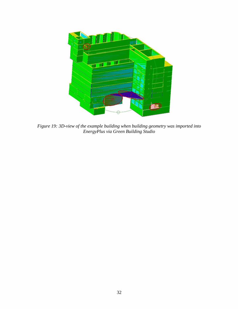
Figure 19: 3D-view of the example building when building geometry was imported into
EnergyPlus via Green Building Studio
32
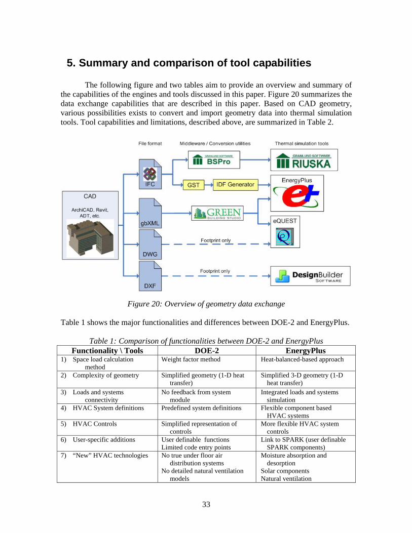
5. Summary and comparison of tool capabilities
The following figure and two tables aim to provide an overview and summary of the capabilities of the engines and tools discussed in this paper. Figure 20 summarizes the data exchange capabilities that are described in this paper. Based on CAD geometry, various possibilities exists to convert and import geometry data into thermal simulation tools. Tool capabilities and limitations, described above, are summarized in Table 2.
Figure 20: Overview of geometry data exchange
Table 1 shows the major functionalities and differences between DOE-2 and EnergyPlus.
Table 1: Comparison of functionalities between DOE-2 and EnergyPlus Functionality \ Tools DOE-2 EnergyPlus
1) Space load calculation method
Weight factor method Heat-balanced-based approach
2) Complexity of geometry Simplified geometry (1-D heat transfer)
Simplified 3-D geometry (1-D heat transfer)
3) Loads and systems connectivity
No feedback from system module
Integrated loads and systems simulation
4) HVAC System definitions Predefined system definitions
Flexible component based HVAC systems
5) HVAC Controls Simplified representation of controls
More flexible HVAC system controls
6) User-specific additions User definable functions Limited code entry points
Link to SPARK (user definable SPARK components)
7) “New” HVAC technologies No true under floor air distribution systems
No detailed natural ventilation models
Moisture absorption and desorption
Solar components Natural ventilation
33
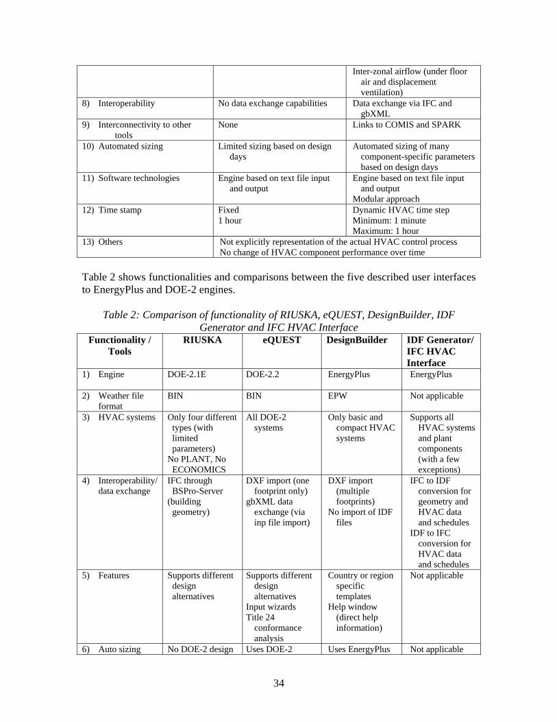
Inter-zonal airflow (under floor air and displacement ventilation)
8) Interoperability No data exchange capabilities Data exchange via IFC and gbXML
9) Interconnectivity to other tools
None Links to COMIS and SPARK
10) Automated sizing Limited sizing based on design days
Automated sizing of many component-specific parameters based on design days
11) Software technologies Engine based on text file input and output
Engine based on text file input and output
Modular approach 12) Time stamp Fixed
1 hour Dynamic HVAC time step Minimum: 1 minute Maximum: 1 hour
13) Others Not explicitly representation of the actual HVAC control process No change of HVAC component performance over time
Table 2 shows functionalities and comparisons between the five described user interfaces to EnergyPlus and DOE-2 engines.
Table 2: Comparison of functionality of RIUSKA, eQUEST, DesignBuilder, IDF Generator and IFC HVAC Interface
Functionality / Tools
RIUSKA eQUEST DesignBuilder IDF Generator/ IFC HVAC Interface
1) Engine DOE-2.1E
DOE-2.2 EnergyPlus EnergyPlus
2) Weather file format
BIN BIN EPW Not applicable
3) HVAC systems Only four different types (with limited parameters)
No PLANT, No ECONOMICS
All DOE-2 systems
Only basic and compact HVAC systems
Supports all HVAC systems and plant components (with a few exceptions)
4) Interoperability/ data exchange
IFC through BSPro-Server
(building geometry)
DXF import (one footprint only)
gbXML data exchange (via inp file import)
DXF import (multiple footprints)
No import of IDF files
IFC to IDF conversion for geometry and HVAC data and schedules
IDF to IFC conversion for HVAC data and schedules
5) Features Supports different design alternatives
Supports different design alternatives
Input wizards Title 24
conformance analysis
Country or region specific templates
Help window (direct help information)
Not applicable
6) Auto sizing No DOE-2 design Uses DOE-2 Uses EnergyPlus Not applicable
34
day sizing Basic sizing
capabilities
design day sizing capabilities
design day sizing calculations
7) Data exchange problems
Floor based IFC import (multiple story spaces)
Internal/external walls/slabs
No plenums available
For gbXML: Incorrect shading
surfaces Missing walls Internal/external
walls
Not applicable To be determined
6. Recommendations
We recommend the following research, development and implementation follow up work related to energy simulation tools which resulted from our experience with
• Using the described tools on a variety of projects o Several projects with RIUSKA at Olof Granlund Oy o The Santa Rosa Federal Building (EnergyPlus) o The new San Diego Federal Courthouse (EnergyPlus) o The new San Francisco Federal Office Building (EnergyPlus) o The Global Ecology Center at Stanford University (DOE-2,
EnergyPlus) • Teaching in the Building Systems class at Stanford University • Developing and implementing
o The GST middleware o The IDF Generator o The IFC HVAC Interface to EnergyPlus o The IFCtoFDD interface o The SMIET tool
In general, data exchange needs to become more reliable and less error prone so that practitioners can integrate these tools more smoothly into practice. Software tools need become more user-friendly, more capable, more robust and better documented. Simulation engines need to become more capable, more robust, and more up-to-date with current computer science technology and new HVAC system types.
6.1. Recommendations for practitioners
The used example building shows that data exchange to and from energy simulation tools is still not reliable enough to be consistently used in real-world projects. Thus we recommend that practitioners demand working data exchange solutions and engage in the research and development process. • Demand for working data exchange solutions
As demonstrated through the example building, inconsistencies that occur in data exchange between the different applications and in data exchanged are time
35
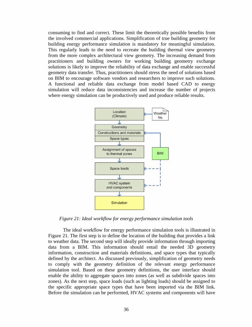
consuming to find and correct. These limit the theoretically possible benefits from the involved commercial applications. Simplification of true building geometry for building energy performance simulation is mandatory for meaningful simulation. This regularly leads to the need to recreate the building thermal view geometry from the more complex architectural view geometry. The increasing demand from practitioners and building owners for working building geometry exchange solutions is likely to improve the reliability of data exchange and enable successful geometry data transfer. Thus, practitioners should stress the need of solutions based on BIM to encourage software vendors and researchers to improve such solutions. A functional and reliable data exchange from model based CAD to energy simulation will reduce data inconsistencies and increase the number of projects where energy simulation can be productively used and produce reliable results.
Figure 21: Ideal workflow for energy performance simulation tools
The ideal workflow for energy performance simulation tools is illustrated in
Figure 21. The first step is to define the location of the building that provides a link to weather data. The second step will ideally provide information through importing data from a BIM. This information should entail the needed 3D geometry information, construction and materials definitions, and space types that typically defined by the architect. As discussed previously, simplification of geometry needs to comply with the geometry definition of the relevant energy performance simulation tool. Based on these geometry definitions, the user interface should enable the ability to aggregate spaces into zones (as well as subdivide spaces into zones). As the next step, space loads (such as lighting loads) should be assigned to the specific appropriate space types that have been imported via the BIM link. Before the simulation can be performed, HVAC systems and components will have
36
to be defined. This should either be done by manual user input or via semi-automated import of HVAC information from the BIM. While the latter is obviously preferred, significant development, implementation and testing still need to be performed in order to enable HVAC related data import for energy simulation tools. Once all these data are defined one should be able to quickly (much quicker than currently) perform a simulation, given input of additional simulation specific parameters (such as numerical tolerances, start and end date of the simulation, etc.).
• Communication with researchers and developers
Practitioners should start or continue communication with researchers and software developers to get a better understanding of current limitations of software tools and their data exchange capabilities, and to gain access to and use of their expert knowledge and experience to successfully use such technologies. Furthermore, practitioners should commit to BIM and the development and spread of standards, test emerging technologies and provide their valuable insights to the R&D community to enable a continuous development and improvement of tools that support practical needs.
6.2. Recommendations for researchers This paper illustrated the strengths and limitations of building energy performance
simulation tools. We recommend that researchers focus on adding important and more advanced functionality to simulation engines, such as two- and three-dimensional heat transfer, event driven simulation architecture, and statistical methods for defining input parameters. They should enhance data exchange solutions with additional data and data set content, and with more reliable data conversion based on BIM. Especially, data sharing over networks, based on model servers, is a major area that needs exploration. Researches also need to work on integrating new advanced data exchange scenarios into today’s common practice to enable more technology benefits for the industry. Lastly, research to integrate energy simulation into commissioning and operations could dramatically improve the value of energy simulation.
• Two- and three-dimensional heat transfer
Researchers should enable two- and three-dimensional heat transfer in building energy performance simulation tools. The one-dimensional heat transfer assumption is inadequate, given possibilities today’s computer power and computer simulation technologies provide (for example, optimization of numerical algorithms or faster and better simulation environments). Furthermore, building geometry has become more complex, and two- and three-dimensional heat transfer is becoming more important to contemporary buildings.
• Event driven simulation
The architecture of all described energy simulation tools is based on fixed or variable time step simulation concept. While there has been improvement to more variable and smaller time steps, event driven simulation would eliminate
37
approximations that result from time steps that are longer than the characteristic time intervals of thermodynamic processes. Event driven simulations would need to perform change-of-status calculations only when changes in the building actually occur and would thus provide a more flexible methodology that can account for changes only when they occur. Thus it would be more flexible to adjust to different time characteristics of processes that usually cannot be reflected in time-step-based simulation.
• Integration of statistical methods
Researchers need to improve the current way of defining simulation input parameters such as internal loads. In practice these input values are based on building or energy codes or reflect the expected worst conditions; they typically do not reflect the actual usage of buildings. Statistical distributions of occupancy and other internal loads could enable more realistic models of building usage and provide a better basis for simulating annual energy consumption in buildings during their design.
• More advanced data exchange based on BIM solutions
Today, several data formats exist to exchange building related information between applications. While some limited solutions exist to exchange data among a small number of applications (such as CAD to energy simulation via DXF), researcher should focus on more sophisticated and thorough solutions such as BIM based approaches that account for data needs over all disciplines and life-cycle phases. The gbXML format provides functionality to exchange simplified building geometry and some limited HVAC information, but needs to be extended to allow data exchange of complete HVAC definitions and schedules. The IFC model intentionally contains more thorough definitions across all disciplines and life-cycle phases. However, for a reliable data exchange these definitions need to be implemented in software applications and thoroughly tested. In addition, model view definitions need to be developed that define at a parameter level how software vendors need to implement the IFC model. These view definitions are necessary to ensure successful data exchange based on the same implementation in all participating software. In particular, the HVAC domain for the IFC model needs such a view definition to provide the foundation for data exchange related to HVAC data. While current data import from model based CAD applications into energy simulation tools is limited to 3D geometry and objects types, additional information (such as construction materials thermodynamic properties) need to be included in the exchange process. Researches should participate in the definition of model views and implementer agreements to expedite the achieving of reliability and transparency in data exchange.
• Implementation of model servers
Researchers should also focus on the realization of model servers based on BIM, possibly as defined in the SABLE project (SABLE 2007). The current file-based data-exchange process provides some benefits to the users, but can be cumbersome if design changes happen often. Model servers would be able to
38
support these changes, so that they can be easily transmitted to and updated in any relevant application. Model servers would also allow collaborative work on the same building project without major time delays between the party making the change and the party affected by it. Server-based BIMs also allow users the flexibility to access the data from anywhere, given an internet connection.
• Changes to industry processes
In conjunction with model server development, research needs to change and redefine current industry business processes. This change is necessary to leverage benefits from advanced data sharing over the internet. Especially, change management could benefit dramatically from BIM-based model servers, where changes can be implemented in real-time or close to real-time. Changes would become more transparent in any given BIM and could improve change-related communication between different industry disciplines. Model servers and their software need to support new emerging business processes in order to be adopted by the industry. When data exchange becomes more reliable and expedient, more timely feedback to different design alternatives or changes should provide valuable insights earlier in the process than is currently possible.
• Use of building performance energy simulation during commissioning and operations While energy simulation tools are typically used during the design phase,
they are capable of usage during commissioning or operations. As described in this paper, software tools and especially their user interfaces do not support the use of these tools during commissioning or operations. In principle, the simulation engines can be used at any point during the life-cycle phase of the building. Thus they could be used as basis to evaluate actual building performance based on the comparison of observations and predictions. A current research project at CIFE is exploring the possibilities for such a comparison (Fischer et al. 2006).
39
7. Conclusion
This paper describes building thermal simulation engines DOE-2 and EnergyPlus, and some of the available user interfaces to these engines. The benefits and limitations of each tool were discussed by describing their functionality, life-cycle usage and data exchange over software boundaries. The user interfaces for DOE-2 are currently more developed in comparison to the interfaces for EnergyPlus. The lack of user-friendly, mature and comprehensive user interfaces limits the usage of building energy performance simulation in practice. Current progress on interfaces to EnergyPlus is promising and is likely to provide adequate user friendliness and functionality in the foreseeable future.
Even though the development of thermal simulation tools has “eased the life” of users, the usage of such tools is not a trivial task and needs an understanding of the described limitations, as well as the knowledge of thermal processes in a building. Thus, any result is only as good as the understanding of its limitations. As outlined in the recommendations, various issues related to thermal simulation tools itself need more development and research to improve the value and accuracy of energy simulation.
The strength of energy simulation today is the comparison of different design alternatives rather than predicting absolute energy consumption values. With additional research and development, these tools could also provide more accurate absolute values and provide many additional benefits to their users.
Current seamless data import of building geometry data into energy simulation tools has limitations and usually includes either a process of iteratively changing the architectural model or manual checking and fixing of the partially converted geometry. The example building shown repeatedly in this document demonstrates the typical and frequently encountered problems with data exchange related to building energy performance simulation.
Energy performance simulation tools are mostly used during design, but the use of such tools during the commissioning and operations phase has additional value. To leverage this value, data exchange must become more applicable and usable in other phases of a building’s life-cycle, not only in the design phase. Thus a closer integration of energy performance simulation with the actual performance of buildings during operation will not only improve existing simulation tools, but will also enable a more efficient operation of buildings.
8. Acknowledgements
The authors would like to thank Olof Granlund Oy for providing the initial IFC model of the example building used to demonstrate data exchange capabilities of the tools.
40
References:
Bazjanac, V. (2002)."Early Lessons From Deployment of IFC Compatible Software." Fourth Euro. Conf. Product Process Modelling, Portoroz, Slovacia, 9-16 pp. ISBN 90 5809 507 X
Bazjanac, V., and Maile, T. (2004)."IFC HVAC interface to EnergyPlus - A case of
expanded interoperability for energy simulation." SimBuild 2004 Conference, Boulder, CO, IBPSA-USA, 7 pp.
Bazjanac, V., and A. Kiviniemi. (2007) “Reduction, simplification, translation and
interpretation in the exchange of model data”. In D. Rebolj (ed), CIB W78, Proc. 24th conf. bringing ITC knowledge to work, Maribor, SI: 163-168. Faculty of Civil Engineering, University of Maribor. ISBN 978-961-248-033-2.
Birdsall, B., Buhl, W. F., Ellington, K. L., Erdem, A. E., and Winkelmann, F. C. (1990).
"Overview of the DOE-2 building energy analysis program, Version 2.1D." Lawrence Berkeley Laboratory LBL-19735-Rev.1, Berkeley, CA. 53 pp.
BLAST. (2003). "BLAST Homepage." http://www.bso.uiuc.edu/BLAST/index.html. Cho, S. and J. S. Haberl (2006). “A Survey of High Performance Office Buildings in the
United States”. H&H - Symposium om Improving Building Systems in Hot and Humid Climates, Orlando, Florida.
COMIS. (2003). "COMIS, Multizone Air Flow Model Homepage."
http://www-epb.lbl.gov/comis/. Crawley, D. B., Lawrie, L. K., Winkelmann, F. C., Buhl, W. F., Pedersen, C. O., Strand,
R. K., Liesen, R. J., Fisher, D. E., Witte, M. J., Henninger, R. H., Glazer, J., and Shirey, D. B. (2002)."EnergyPlus: New, Capable, and Linked." eSim 2002 Conference, Montreal, Quebec, Canada, IBPSA-Canada, 10 pp.
Crawley, D. B., Hand, J. W., Kummert, M., and Griffith, B. T. (2005)."Contrasting the
Capabilities of Building Energy Performance Simulation Programs." Proceedings of Building Simulation 2005, Montreal, Quebec, Canada, IBPSA, 231-238 pp.
California Energy Commission. (2007). "Title 24, Part 6, of the California Code of
Regulations: California's Energy Efficiency Standards for Residential and Nonresidential Buildings." http://www.energy.ca.gov/title24/.
DesignBuilder. (2007). "DesignBuilder Software Homepage."
http://www.designbuilder.co.uk. EnergyPlus. (2007). "EnergyPlus, Getting started with EnergyPlus."
http://www.eere.energy.gov/buildings/energyplus/documentation.html.
41
eQUEST. (2006). "eQUEST…the Quick Energy Simulation Tool, An overview."
http://www.doe2.com/download/equest/eQUESTv3-Overview.pdf. Fischer, M, Bazjanac, V, Maile, T. (2006) “Improving and Verifying Building
Performance”, CIFE Seed project, http://www.stanford.edu/~tmaile/SP Green Building Studio, Inc. (2007 a). “The Green Building Studio for ArchiCAD“
Tutorial for Version 3.0, 32 pp. http://www.greenbuildingstudio.com/Tutorial.aspx Green Building Studio, Inc. (2007 b). "Green Building Studio – website”,
http://www.greenbuildingstudio.com Granlund. (2007a). "BSPro Server homepage." http://www.granlund.fi/bspro/. Granlund. (2007b). "Olof Granlund Oy, Company homepage." http://www.granlund.fi/. International Alliance for Interoperability (IAI). (2007). "International Alliance for
Interoperability (IAI) - North America - Homepage." http://www.iai-na.org/. International Energy Agency (IEA). (2007). "International Energy Agency - Homepage."
http://www.iea.org/. Jokela, M., Keinänen, A., Lahtela, H., and Lassila, K. (1997). "Integrated Building
Simulation Tool - Riuska." Insinööritoimisto Olof Granlund Oy. Juha-Matti, K. (2003). "Use of Building Information System to Analyze Energy
Performance," Master Thesis (in Finnish), Tampere University of Technology. E. Kolderup, T. Hong, L. Miller, A. Rendek, A. Daly, G. Paliaga, D. Goldman, J. Arent,
A. Tahir, J. Kennedy, S. Blanc. (2006) “Evaluation of Green Building Studio”, Application Assessment Report # 0501 prepared for Pacific Gas and Electric Company, p. 134, 23 October 2006
LBNL. (2003). "VisualSPARK2.0 User Guide."
http://simulationresearch.lbl.gov/VS201/doc/VisualSPARKusersGuide.pdf. LBNL. (2007). "EnergyPlus homepage." http://www.energyplus.gov. Progman Oy. (2007). "MagiCAD homepage." http://www.progman.fi/. Southern California Edison (SCE). (2007). "Southern California Edison - Homepage."
http://www.sce.com. SPARK. (2007). "VisualSPARK - Homepage." http://gundog.lbl.gov/VS/spark.html.
42
Simulation Research Group (SRG), Lawrence Berkeley National Laboratory and James J. Hirsch and Associates. (1998). "Overview DOE-2.2." http://www.doe2.com/Download/Docs/22_oview.pdf.
Strand, R. K., and Pedersen, C. O. (2001)."Modularization and Simulation Techniques
for Heat Balance Based Energy and Load Calculation Programs: The Experience of the ASHRAE Loads Toolkit And EnergyPlus." Proceedings of Building Simulation 2001, Rio de Janiero, Brazil, IBPSA, 43-50 pp.
TRANSYS. (2007). "TRANSYS - Homepage." http://sel.me.wisc.edu/trnsys/. U.S. Department of Energy (U.S. DOE). (2007). "Building Energy Software Tools
Directory." http://www.energytoolsdirectory.gov Winkelmann, F. C., Bridsall, B. E., Buhl, W. F., Ellington, K. L. and Erdem, A. E.
(1993). "DOE-2 Supplement Version 2.1E", LBL-34947, November 1993, 810 pp. Xu, P., Haves, P., and Deringer, J. (2004)."A Simulation-based testing and training
environment for building controls." SimBuild 2004, Building Sustainability and Performance Through Simulation, Boulder, CO, USA, 8 pp.
Xu, P., Haves, P., and Moosung, K. (2005)."A Semi-Automated Functional Test Data
Analysis Tool." 13th National Conference on Building Commissioning, New York City, NY, May 4-6, 2005, 13 pp.
43