Embed Size (px)
Citation preview
Circuit Board Diagnostics
NOTE: Discharge your body’s static
electricity before touching unit. An
electrostatic discharge can adversely
affect electrical components.

Troubleshoot Integrated Control Module
• Set thermostat to call for heat, and test for 24 volts at “W1” and “C.”
• If NO 24 volts read, check transformer, thermostat, and wiring.
• If transformer power is producing 24 volts, but terminal board only receiving 13 volts between “C” and “R,” check 3A fuse. (on board)
If 120 Volts is Present on the Board
24 volts to board
Neutral wire

Troubleshoot Integrated Control Module- GMVC96
• Set thermostat to call for heat, and test for 24 volts at “W1” and “C.”
• If no 24 volts read, check transformer, thermostat, and wiring.
• If transformer power is producing 24 volts, but terminal board only receiving 13 volts between “C” and “R,” check 3A fuse. (on board)
If 120 volts is Present on the Board
3A fuse

Troubleshooting Furnace Circuit Boards
1. Is there a blink code or the code from Digital
Display?
2. Does the furnace have a good earth ground?
3. Is there 120 volts (+ or – 10%) to the board?
4. Do you have 24 volts to the board?
5. On Communicating Furnaces is the
communications light flashing?
Troubleshooting Furnace Circuit Boards (continued)
6. Turn the T-stat on and give it a call for Fan on . Is
there 24 between G Terminal and common?
7. Check the Molex plug. Does it show signs of
corrosion?
8. Are all the stake on tight, and no signs off corrosion?
9. Take the T-stat wire off of the board. Now use a
jumper wire to make your call. Example: R to G
terminals calling for fan.

GMSS Diagnostic Codes

Troubleshoot Integrated Control Module
• The ground wire must run from the furnace all the way back to the electrical panel.
• Proper grounding can be confirmed by disconnecting the electrical power and measuring resistance between the neutral (white) and the burner closest to the flame sensor.
• Resistance should be less than two (2 ) ohms.
Check for Proper Furnace Ground (GMEC96 and GMVC96 ICM’s)
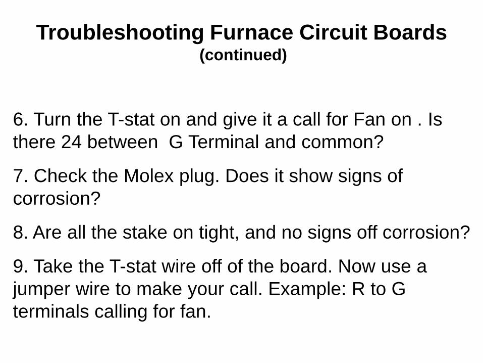
Ignition Control Grounding
Field Measurements
Measure the AC voltage
between Line Neutral
(spade terminal) and “C”
(Thermostat Terminal
Block) on the control
This voltage should be
less than 2 VAC

Ignition Control Grounding
Cycle the control so that the
inducer and circulator blowers
are operated
The voltage should not vary
An indication of a poor or partial
ground is a varying voltage
between Line Neutral and “C”

Ignition Control Grounding
Field Measurements
Measure the AC voltage between Line Neutral (spade terminal) and “C” (Thermostat Terminal Block) on the control
This voltage should be less than 2 VAC

Ignition Control Grounding
Cycle the control so that the
inducer and circulator blowers are
operated
The voltage should not vary
An indication of a poor or partial
ground is a varying voltage
between Line Neutral and “C”
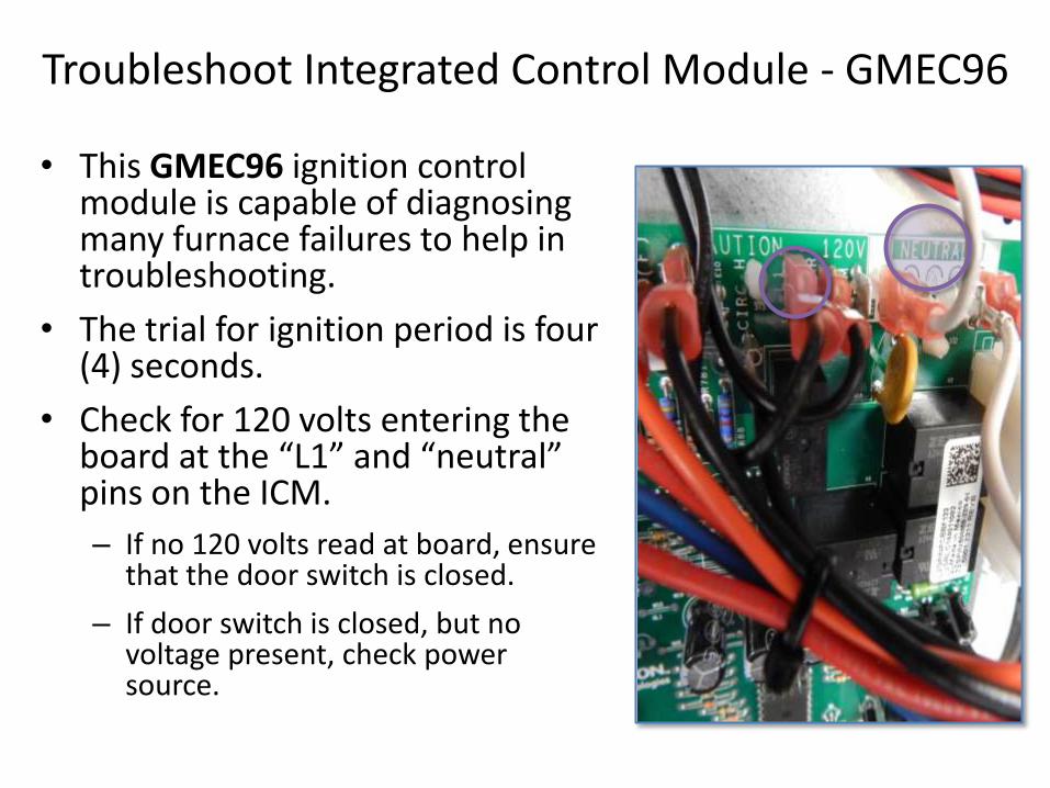
Troubleshoot Integrated Control Module - GMEC96
• This GMEC96 ignition control module is capable of diagnosing many furnace failures to help in troubleshooting.
• The trial for ignition period is four (4) seconds.
• Check for 120 volts entering the board at the “L1” and “neutral” pins on the ICM.
– If no 120 volts read at board, ensure that the door switch is closed.
– If door switch is closed, but no voltage present, check power source.

Test for 120 volts AC

IFC Main Harness Connector
• 15 Pin Connector – Pin 1, Limit Switch Input – Pin 2, 1st. Stage PS Input – Pin 3, No Connect – Pin 4, Hot Side Transformer – Pin 5, Earth Ground – Pin 6, No Connect – Pin 7, Pressure Switch Output – Pin 8, Main Valve Common – Pin 9, No Connect – Pin 10, Hot out to LS – Pin 11, 24 Common – Pin 12, 2nd. Stage PS Input – Pin 13, Low Gas Valve Main – Pin 14, High Gas Valve Main – Pin 15, No Connect

Troubleshoot Integrated Control Module
• Check for 24 volts to the gas valve.
• Voltage will be present for four (4) seconds, only if proof of flame has been established.
• If no 24 volts to gas valve via board, remove 12-pin plug from ICM, and test power directly on board plug, pin #1.
• If board is not supplying 24 volts, replace board.
After Ignitor Warm-Up Time

Troubleshoot Integrated Control Module- GMVC96
• This GMVC96 ignition control module is capable of diagnosing many furnace failures to help in troubleshooting.
• When the control is powered up normally, the light will be on continuously.
– The display will indicate “On” when powered in stand-by mode.
– This can be used to test for 120 volts and 24 volts, as it won’t light up unless both are present.
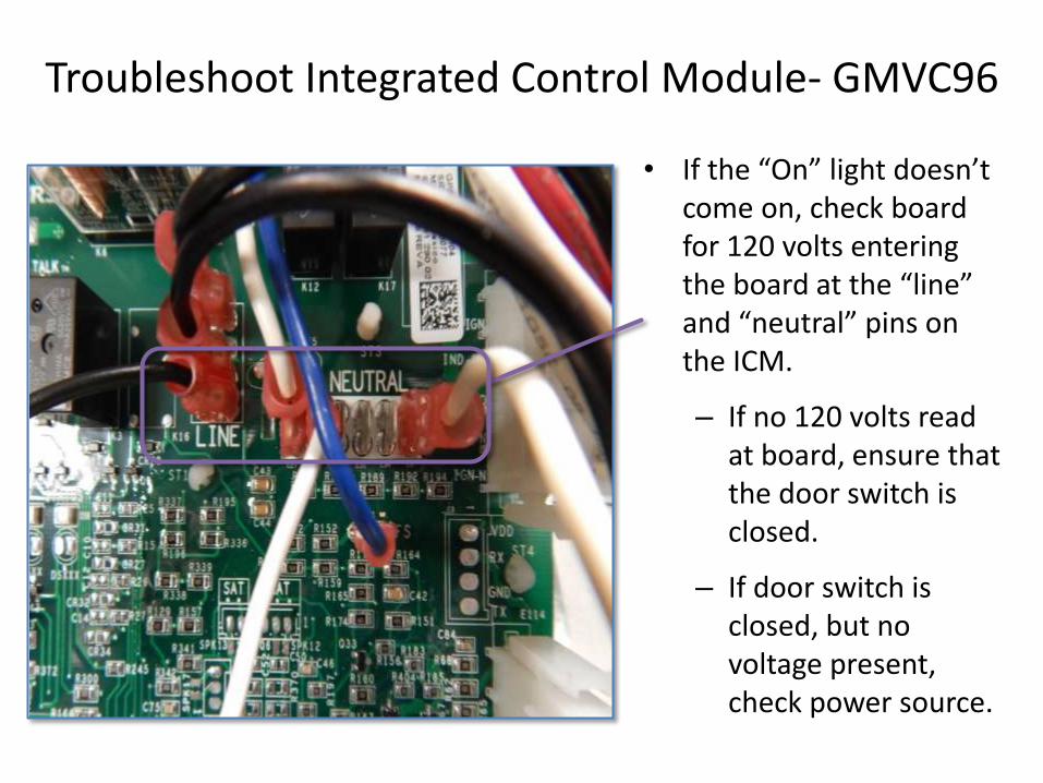
Troubleshoot Integrated Control Module- GMVC96
• If the “On” light doesn’t come on, check board for 120 volts entering the board at the “line” and “neutral” pins on the ICM.
– If no 120 volts read at board, ensure that the door switch is closed.
– If door switch is closed, but no voltage present, check power source.
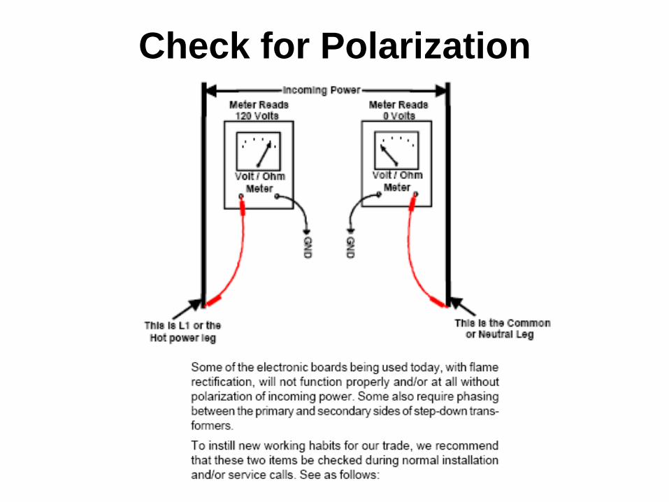
Check for Polarization

Checking for Phasing