Embed Size (px)
Citation preview

1576Circular
C. W. MCMILLIN AND J. L. LVBDNCentral Research Laboratory,
American Machine and Foundry Co.,Stamford, Conn.
Net power required to
saw certain wood species was
determined under various
conditions. For flat-sawn
hard maple, one formula
accurately covered effects
of depth of cut, direction
of cut, and feed rate. Fig. 4.-Tooth Configuration of 16.in. combinotion sowblode used in the experiments.
<!=workpiece d~th (depth of cut)-in.R=radius of sawblade--in.h=distance from axis of sawblade to
workpiece surface-in.f =sawblade protrusion beyond the work-
piece-in.b=arc of sawblade rim engagement in
workpiece-in.W -=angle at start of sawblade rim en-
gagemenr-radiansWt=angIe at exit of sawblade rim en-
gagement'~radiansA, B } constants associated with woodC" c. fIber orientation and structure,c.. Co in various cutting power for-G, E mulas
c =cutting velocity-fpmp =tooth pitch of sawblade--in.&=orientation of sawblade plane with
respect to the grain. The refer-ence e = 0° is taken as perpen-dicular to the grain, which is thecrosscut direction in straight-grained lumber (Fig. 2). 'theacDgle e is interchangeably re-feited to as "the cutting direc-tion:' e = 0° and 90° nor-mally correspond to crosscuttingand ripsawiog, respectively.
Interchangeable temlS that refer tothe sense of sawblade rotation relativeto the feed are tabulated below:
1 2
miter cutting angle in the generalsense, which includes all directionsfrom the cross to the rip {'Osition.Comparative data are also given on"up" and "down" ripsawing.- No ex-perimental evaluation of sawed surfacequality is included.
Many circular sawing Studies pre-sented in the past have failed to reportsuch significant quantities as static a.nddynamic runout, tooth height varia-tion, and other readily measurablequantities. Such quantities should besystematically measured and reported,so that research results can be evaluatedproperly by other investigators. Thepurpose of this research, however, isto obtain data sum as might be ex-~ed under the comparatively uncon-trolled conditions that exist in practice.No effort was made to condition thesawblade to any particular degree ofroundness, flatness or sharpness.
Nomenclature
The terminology adopted for use inthis study is defined &elow, in con-venient engineering units. Geometricalrelations are shown in Fig. 1:
P=net cutting power--bpf =f~ rate-fpmk=actua! kerf width-in.
S EVERAL YEARS AGO, the American
Madtine and Foundry Co. decidedto conduct a comprehensive investiga-tion in the field of cutting processes.The initial emphasis has been on cir-cular sawing Eecause of the productline of the company's Dewart Divi-sion. As a necessary antecedent to theo-retical and experimental investigations,an extensive review of the literature oncircular sawing was undertaken byLubkin (l)a. Although considerablequantities of information are availableon ripsawing, virtually no informationwas discovered on crosscut or mitersawing of wood. The latter operationsare important and are the principalcuts for which radial-arm saws areused.
Accordingly, a broad program ofsawing research was established, aimedat objectively defining the basic rela-tionships and principal variables. Aprogram such as this naturally includesconsideration of such factors as netcutting power, cutting geometry, sur-face finish, tool life, and others factorsthat enter into machinability andequipment design.
The research summarized in thispaper is part of this continuing Pro- (a) up cutting d~wn eutting
. '" (b) nOml&i aWing cI1mb ..~gram, which IS Intended to obtain sys- (e) eounter awinc eUmb 8&wi!1lt tj. .nf tj. th ~ (d) sawlnc acainat the feed awing with the feedema C I orma on on e Orln-
ance of circular sawblades an circular Experimental Procedure-sawing machines. The effect on net .. .cutting power of such variables as DeSIgn of .the Exper1lDents.: Fivewood species, feed ute, depth of cut, separ~te experllD.ents wer~ reqwred toand cutting direction has been meas- establish. the desired relations betw~ured for a combination-type sawblade. n~t CI;ltting ~wer, feed rate, cuttingCutting direction is defined here as the direction, and depth. of cut. Except- TN A.",,: Charles McMillin holds a BS in where noted, all saWIng was done as
1 Presented at Session In, Wood Machining, forestry and wood technology from Purdue. andFPRS l~th Natiooal Meetin" June 28-July ~, a MS in wood technology from the U. of . These definitions are for "climb sawin."1959. in San Francisco. Michigan. He is s res~arch ~ngineer for AMF. and a clockwis~ rotation in Fig. 1. For "nor-
I Numben in parentheses reler tn the Litera- James Lubkjn bolds BS and MS d~grees in mal" sawing. the direction 01 rotation i. op-ture Cited at the end of this report. mechanical engineering and a PhD in applied polite (counterclockwise) and the subscriPts of
a S;ee "Nomenclature" s~(:tlon. for other mechanics fr!lm Columbia Univ. He is a senior W, and W. must be interchang~d in the
terminology commonly used 1n pramce. research engIneer at AMF. diar.ram.
Reprinted from the October, 19~9, Forest Products Journal (Vol. IX, No. 10), pages 361-367Forest Products Research Society, 417 North Walnut Street, Madison ~, Wisconsin

-=-::.:...: ~~~~~~~. -
~~~~~:?./ClOSS CUT.I \ MITEI CUT
Fig. 2.-Oeftnition of cutting direction(6). The ongle 6 gives the orientotion ofthe sowblode plone with respect to thegroin. As indicoted. e = o. is token to b.perpendicular to the grain (cross-cut direc-tion for straight-grained lumber). Rip-sow-ing corresponds to e = 90..
Fig. 1.-Geometrical relatianl in circularlowing with a radial arm saw. Sawblade ilfed from left to right. Clockwile rotationreprelents climb sawing and counter clack-wile rotation correspond I to normal lowing.
shown in Fig. 3. The machine is basic-ally a standard, industrial, radial-amtsaw with a 28-inch crossfeed stroke.The sawblade and yoke assembly aredriven across the radial arm by an aircylinder equipped with a hydraulicdleck valve. Preliminary e~enta-tion revealed that noload feed speedsdeviated less than r¥2 percent from apreset feed rate. The sawblade wasdriven by a 7.5 hp, 3 phase, 60 cycle,220/440 volt induction motor. A fix-ture attadled to the saw table facili-tated ~sitive clamping of the work.piece. The sawblade was mounteddirectly on the I-inch diameter motorarbor by means of the standard 4-inchcollar set normally furnished with themachine.
The average ~wer input to the sawmotor was measured With a SanbornAC Wattmeter preamplifier (Model150-2300). This is one of severalstandard plug-in units for the Sanbornoscillographic recorder employed inthis study.
Sawblade Used: Fig. 4 is a close-upview of the sawblade Used in theseexperiments. The blade is consideredto be of excellent commercial quality,and was used in the as-received condi-tion. No effort was made to conditionit to any particular degree of round-ness, flatness, or sharpness. Typicaldata for sawblades made by the samemanufacturer indicate that the arborhole will normally be 0.0015 inchabove nominal bore size. This type ofblade is hand-filed and shows a toothheight range of 0.005 inch on the scor-ing (high) teeth. It has a 0.010-inchrange on the raker (low) teeth, whichare about 0.030 inch below the nom-inal scoring tooth diameter.
During the course of the ~ri-ments, the blade was inspected forgwnmy deposits on the teeth and gul-lets, which were then removed withcarbon tetrachloride. A preliminary ex-periment with an identical blade re-vealed that significant dulling effectsare not measurable with the compara-tively small amount of material sawedin these studies.
Actually, two different sawblades ofthe same type were used in these tests.Experiment 1 was conducted with oneblade, and the rest of the studies witha second blade of nominally identicalspecifications. These are as follows:
diameter-16 in.; type--<ombinatioo;grind-Bat; thickness-O.097 in.; nom.inal set-O.025 in. per side; actual kerf-0.16 in.; 00. of teetb-72; no. ofgroups-24; DO. of scorer&-48; collardiameter-4 iJL; front & top bevel angle(scorers)-100; clearance angle (scor.ers)- 30°; clearance angle (rakers)-20 ; hook angle (scorers)-100; bookangle (rakers)-27°; rakers have noadaitional bevel angles.
Preparation of Test Material: Allexperimental material was conditionedfor several months in a constant tem-perature and humidity chamber. Thisresulted in the eqUilibrium moisturecontents listed in tile experimental de-sign. Sufficient test material was thenselected from the conditioned stock.Only Bat-sawn, defect-free, straight-grained material was used. Two-foot-long test ~ens were p~ andsuitably randomized, so that each re-plication of the experiments was madeon a different specimen. The experi-mental material was then surfaced tothe required thickness and returned tothe conditioning chamber for oneweek.
Method of Cutting: Before anymaterial was cut, the saw motor wasallowed to operate for at least 20 min-utes. Ex~rimental material was thenremoved from the conditioning cham-ber in small quantities so as to min-imize moisture-content manges duringcutting. A special fixture was used toassure ~itive clamping of the work-piece to the saw tab1e. Individual cutswere made 1 inch from the end of thetest s~n to avoid the false powerreadings that may result from cuttingtoo close to a free edge. Moisture con-tent and ~pecif1c gravitr samples weretaken dunng the expenments to detectany substantial variation in these prop-erties.
All ripsawing .opera.tion~ were per-formed by tht air-hydraulic crossfeed
normally performed on radial armsaws. That is, all types of miter cuts,including crosscutting, were "climb"cuts, while ripsawing was performed as"counter" sawing. The following ex-perimental designs were adopted:
Exp".iment No.1Species-Hard maple (At"" S4t"t"b.#11I
Marsh.), Douglas-fir (Pse*a'ots*gaMenu,si; (Mii-b.) Franco) and sugar
pine (Pi.1IS Llmb".,i." Dougl.)Feed. rate--l0, 20, 40 and 60 feet per
D11nuteCutting dilection (9)-0, 4' and 90 de-
greesExperiment No.2Species-Hard maple (At"'" saft"hIIr*m
Marsh. )Feed rate--l0, 20 and 40 feet pet minuteDepth of cut-lIs, If., 1/2, 1, lYz, 10/4,
21f8, 31/4 and 'Y8 inchesCutting direction (6)-0 degreesExp";ment No. .3Species-Hard maple (Af". saft"har*m
Marsh. )Feed rate--20 feet per minuteDepth of cut-If., 1/~, 1, l¥z, 1% inchesCutting direction (6.,-0, 4' and 90 de-
greesExperimnt No.4Species-Hard maple (At"" s4t"t"har*mMarsh. )Feed rateo-l0, 20 and 40 feet per minuteCutting direction (9)-90 des., countet
and climb sawingExperimnt No. ,Species-Hard maple (At"'" s4t"t"hllrllm
Marsh.)Feed rate--l0, 20 and 40 feet pet minuteCutting direction (9)-0, 22.', 4', 67.5
and 90 (climb sawing) degreesThe following were held constant in
all the foregoing experiments:1. Equilibrium moisture content-
sugar pine, 9 ~rcent; Douglas-fir, 9 ~rcent; hard maple, 11
~rcent2. All experimental material was
carefully selected from flat-sawn,defect-free, straight-grained lum-ber.
3. Sawblade protruSion below theworkpiece was 1/16-in.
4. Rotational speed was 3600 rpm(3450 rpm at 7.5 hp motor
load)5. Sawblade was a 16-inch, flat-
ground, combination-type blade.
Three repliCations, one each on threeboards, were performed for each cut-ting condition listed in the ~rimen-tal design. This was found to be ade-quate in a preliminary ex~riment toyield a standard deviation of 1.73 ~rcent of the mean for the worst case.Thus, by ordinary statistical reckon-ing a band of ~ 3.5 percent of themean should represent a 95 percentconfidence coefficient This is not toimply that less carefully selected andconditioned stock will not give a larger
spread.Experimental Apparatus: A gen-
eral view of the experimental area is
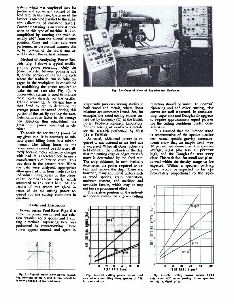
Fig. 3.-General View of Experimentol Equipment.
direction should be noted. In normalripsawing and 4~ 0 miter cutting, thecurves are well separated. In crosscut-ting, sugar pine and Douglas-fir appearto require approximately equal powerfor the cutting conditions under con-sideration.
It is assumed that the lwnber usedis representative of the s~ies undertest. Actual specific gravIty measure-ments show that the maple used was10 percent less dense than the speciesaverage, sugar pine was 10 percenthigh, and the Douglas-fir was veryclose. This variAtion, for small samples,is wdl within the density range to beexpected. Within a s~es, cuttingpower would be expected to be ap-proximately proportional to the spe-
system, which was employed here forprecise and convenient control of thefeed rate. In this case, the grain of thelumber js orientedr arallel to the radialarm (direction 0 crossfeed travel).Counter ripsawing is an unusual oper-ation on this type of machine. It is ac-complished by rotating the yoke as-sem&ly 1800 from the normal crosscutposition. Cross and miter cuts wereperformed in the normal manner; thatis, by rotation of the radial arm as-sembly about the vertical column.
Method of Analyz;ing Power Rec-ords: Fig. 5 shows a typical oscillo-graphic power recording. Only thepower recorded between points A andB, or the portion of the cutting cyclewhere the sawblade rim is fully en-gaged in the workpiece, is consideredin establishing the power required tomake the cut (see also Fig. 1). Amicroswitch system is used to indicatethese points directly on the oscillo-graphic recording. A straight line isthen fitted by eye to determine theaverage power consumed during thisportion of the cut. By appling the watt-meter calibration factor to the averagepen deflection thus established, thegross input power consumed is ob-tained.
To obtain the net cutting power forany given run, it is necessary to sub-tract system idling losses in a suitablemanner. The idling losses on thepower records cannot be subtracted di-rectly because motor efficiency changeswith load. It is therefore best to use amanufacturer's calibration curve. Thiswas done in the present case. Whenthe data were analyzed, appropriateallowance had thus been made for theindividual idling losses of the blade-collar combination used, whichamounted to 157 watts here. All theresults of this report are given interms of the net cutting power re-quired for the cutting conditions inquestion.
shape with previous sawing studies inboth wood and metals, where linearrelations are commonly found. See, forexample, the wood-sawing studies car-ried out by Endersby (2) at the BritishForest Products Research Laboratory.For the sawing of nonferrous metals,see the research performed by Nuss(4) at DeWalt.
As usual, additional power is re-quired to saw material as the feed rateis increased. When all other factors areheld constant, the thickness of the chipthat the cutting edge or edges must re-move is determined by the feed rate.The chip thickness, in turn, basicallyd~termines the power required to de-tach and remove the chif' There are,however, many additiona factors suchas wood sp:cies, grain orientation,moisture content, and machine andsawblade factors, which mayor maynot have a pronounced effect.
The relative position of the individ-ual species curves for a given cutting
Results and DiscussionPower versus Feed Rate: Figs. 6-8
show the power versus feed rate rela-tion obtained for 3 species and 3 cut-ting directions. Ripsawing here wasperformed by countersawing. Thesecurves appear normal, and agree in
18-0...
~51~t-t-="":t-~ ~
. 10 20 30 40 50 60
FEED RATE (fpm)
fig. 7.-Net cutting power venus feedrote when 45° miter sowing three speciesot 1" In. depth of cut.
. II 21 38 4G 50 .
FlED lATE (f,m)
fig. 6.-Net tuNing power versus feedrate when crosscuNing three species 01 1"in. depth of cut.
Fig. 5.-Typical motor input power record-ing. Between paints A and B, the sawblodeis fully engaged in the workpiece.

Y.fig. 10.-Ielatlon af dimensionless arc
ratio b/l (ongl. of sow ri. .ngag.",ent)to di",ensionl.1I wwkpiece depth ratio d/l.Sawblod. operoted at 1/16.in. ftxed pro-trusion (fIR = 1/128).. 11 a 18 40 . .
FEED RATE (Jpm)
Fig. '.-Net cutting power yersul feedrate when (counter) riplowlng three specielat 1" In. depth of cut.
-' 1 2 3 4 5 &
DEPTH OF CUT (in.)
fig. 9.-Net cuffing power venus depthof cuI for thr.. feed speeds. Nu..ben ne.tto curves give feed speed in fpM.
proportional to a in the sccond term,provided b is also proportional to a inthe first term. This Woold constituteanalYt;ial support for the form of theexpenmental curve.
It can be shown, however, that b isnot di1'ectly proportional to a for smalldepths of cut. Radial-arm sawingmadtines are normally used to sawwood with a small. fixed blade protru-sion f. This is generally found tobe the most efficient cuttmg positionfor wood (1,5), although elsewhere itis found to be the least efficient forsawing metals (4). The arc of saw-blade rim engagement can be alculatedon the basis of cutting geometry frcnthe following (see Fig. 1):
b=R(W.-W1) (3)Fig. 10 shows the relation of thedimensionless ratios blR and aiR forthe sawblade in question, operated ata fixed protrusion of 1/16 inch.
Actually, b is not proportional to a.Because of the nature of wood, how-ever, two other facton enter the pic-ture. First of al1. the contriOOtion ofthe first tem1 in Eq. (2) is normallymuch smaller than that of the secondterm, at most feed rates of a practicalorder of magnitude (assuming a rea-sonably sharp sawblade). On this basisalone it wOOld be reasonable to ap-proximate b by a suitable meanstraight line through the ori~in, forpurposes of the present analysiS.
Secondly, again because of the na-ture of wood, parameters such as C1and C. actually Clepend upon the grainorientation relative to the cuttingedges of the sawblade. In fact, this~ to be the only way to account forprevious experimental work, whim al-most always shows that it is slightlymore efficient to ripsaw wood with asmall blade rrotrosion than with alarge protrusion. With an argument
cific gravity of the ~culat woodsample involved. I~ adjustments aremade to some arbitrary standard ofspecific gravity (such as a reponal ornational average), the relative posi-tions of the curves of Figs. 6-8 willmange slightly. For this reason. anycutting-power value presented here orelsewhere cannot be taken as absolutewithout a close statement of specificgravity, and the many other [actorsthat significantly affect the cuttingresistance of wood.
No evaluation of the ~ty of thesawed surface was made in this study.However, visual examination of speci-mens indicated that, in general, thegreater the feed rate, the poorer thequality of the sawed surface. Since in-creasing die feed rate increases thefeed per tooth, it is reasonable that thesawed surface would refiect increasedsurface roughness.
Power versus Depth of Cut: Fig.9 shows the relation of net cuttingpower to depth of cut for three feedspeeds, when hard maple is crosscut.A concave-upward tendency is appar-ent for small depths of cut, partiaifarlyat the slower feed speeds. After a cer-tain small depth o[ cut is reached, adirect proportionality to workpiecethickness may be considered to exist.These results are in agreement with theexperiments of Lotte and Keller (5),who also appear to have worked with asma1I, fixed protrusion of the saw-blade through the workpiece.
The present results are not to becom~ dirf!dJy with the many otherstudIes of effectS of workpiece thick-ness. This is because most other testshave been conducted on types of
equipment, sum as bendt or mill saws,where it is normal to keep fixed thedistance h between the saw arbor axisand the table or carriage. Thus the ex-periment is conducted with varyingsawblade protrusion as the workpiecethickness is varied, whereas in the pre-sent tests and those of Lotte and Keller(5), the sawblade protrusion is heldfixed at a small amount. Endersby (2)has given a clear picture of the situa.tion where the table height is heldfixed.
It should be pointed out that thisentire study has been conducted withcarefully selected, fiat.sawn lumber. Ifit is suitably oriented, quarter.sawnlumber may be expected to give slightlydifferent results.
The following formula is given byHarris (6) to determine the rower Pf.e:({Uired for a given set of cutting con-dibons with a spring-set ciroI1ar saw ofuniform tood1 pitdt:
P = k (Abc/2p + Bfd] (1)Here A and B are constants that de-pend upon wood properties and orien.tation relative to the sawblade, f is thefeed rate, Ii is the depth of cut (work-piece thickness) , and b is dte arclength of sawblade rim engagement.Since the cutting velocity c, the tood1pitdt' P and the kerf widdt i. ateconstant in this experiment, Eq. (1)may be rewritten with modi6ea con-stants as:
P = ~b + qd (2)The results shown in Fig. 9 are in
agreement with Eq. (2), where P isI Althou,h Eq. (1) is Itrictlt Ippliable to
lawblldes with uniform tooth plkh. it is clearin priDdPcle that it can readn, be esteoded toaccomaaoaate combinatioa-type alwblade.
4

-Do.&
ill25foD-_&--=""'2-...-
0 ! 23456
DEPTH DF CUT (in.)
Fig. !!.-Net cutting power versus depthof cut for three feed speeds (test dotaft"ed by straight lines). Numbers next tocurves give feed speed in fpm.
DEPTH OF CUT (in.)
Fig. 12.-Net cutting power versus depthof cut for three cutting directions.
climb sawing (also as usual). Thesecurves have been drawn with a slightconcave-upward curvature for smalldepths of cut, which is the trend shownin Fig. 9. If the reasoning employed inre-drawing Fig. 9 to Fig. 11 is con-sidered, however, it can be seen that aformula such as Eq. (4) will alsO besufficiently precise (or all cutting direc-tions. Suitable constants Ca and C4must, of course, be determined for thecutting direction in question. In otherwords, the data of Fig. 12 can likewisebe fitted ~te accurately by straightlines through the origin.
Effect of Oimb versus CounterRipsawing: Examination of Figs.6-8 reveals that, under certain cuttingconditions, 450 miter sawing appearsto require as much (or more) power asripsawing. The following is an ex-planation of this apparent inconsis-tency .
Radial-arm saws normally operAte ina climb-type cut for cross and mitersawing for all miter angles short ofthe rip position. Ripping, however, isusually performed &y counter sawing.Climb and counter sawing, as may nowbe seen, ~uired different amounts ofpower and hence must be carefully dis-tinguished in all discussions of sawingdirection.
Fig. 13 is a comparison of the netcutting power required for rippinghard maple by cfurib and counter saw-ing. Climb sawing requires Substan-tially more power than does countersawing. The amount is about 25 percent for this case. These results areconsistent with studies conducted inSweden and Norway on bench andtable saws (3).
The Swedish-Norwegian studiessuggest that climb ripsawing is readilypracticable if negative hook angles areemployed. Cutting powers are then 50to 70 percent greater than for countersawing, however, because of the unfav-orable (negative) hook. Climb cuttingwith blades ground with normal posi-tive hook angles is found to be un-stable in long cuts because of a ten-dency to overheat. This is attributed tosuch factors as 1) a greater mean saW'-dust movement in the gullet, and 2)less favorable motion of the sawdust:while in the gullet of the saw. Bothof these factors tend to give more op-portunities for the sawdust to escapefrom the gullet area and increase fnc-tional rubbing. The rubbing action, inturn, generates sufficient heat to pro-duce thermal instability in the blade.
Actual sawdust motion was studiedphotographically with a special 0.3-microsecond stroboscopic ftash camera.The photographs were taken throughtwo transparent plastic plates, whichwere fixed to the sawblade and rotatedwith it. Narrow wood specimens werethen fed between the plastic plates.Such factors as clearance angle,"shock" loading on tooth entry intothe cut, and gullet clogging are alsoconsidered as ~ssible causes of over-heating, but are discounted on the basisof various theoretical and experimentalconsiderations.
On the basis of the Swedish-Norwe-gian studies, climb ripsawing with theblade used in the present tests wouldbe expected to show up even less fav-orably than is indicated by Fig. 1 30 .This is because the present experimentswere conducted with very short speci-
along the latter lines, it is possible togive a reasonable explanation for theshapes of the experimental curves inFig. 9. The minor variations involved,however, are more of academic thanof practical significance.
It therefore seems sufficient for thepresent purposes to do the following.In Eq. (2), consider C1 and Cz to beso altered that it can be written ap-proximately:
P = d [C. + C.f} (4)This indicates that net cutting poweris a linear function of feed rate, whichis adequate to describe the results ofmost experiments. Also, net power isdirectly proportional to workpiecedepth. This is well supported by theresults of Fig. 9, except at very smalldepths of cut. To show how well thedata of Fig. 9 can be represented bystraight lines through the origin, thesame points are fitted by straight linesin Fig. 11. The fit is seen to be verygood.
While Eq. (4) is sufficiently accu-rate for engineering analysis of theeffects of feed rate and depth of cut,it must be remembered that the "con-stants" C~ and.C. a<:tUallY depend uponwood.fiber orIentation relative to thecutting edges. Their values must beobtained by matchit;1g the formula inquestion to suitable experimental re-sults. This is further clarified by thedata to be discussed now.
Fig. 12 is a comparison of relationof net cutting power to depth of cutfor the rip, 450 miter, and crosscutdirections In hard maple. Ripsawing isperformed here as up-cutting, whilethe other operations are performed as

.
IZ;
II 0.Ti
-.
~,. I 20 . . . 100
I-CUTTING DIIECTION (4.,.)fig. 16.-Oiagram far evaluation af
clltVe.ftt, net cutting power versus cuttingdirection for three feed speeds In fpm.Curves are drawn from Eq. (7). Originoltest data are olio shown.
. D 2D 4D 60 80 I.
I-CUTTIN6 DIRECTION (deg.)
Fig. 14.-Net cutting power versus cuI-ting direction (8) for three feed speeds.Numbers next to curves give feed speed infpm.
behavior of the saw. To show 'Whatcan be done in this res~ the con-stants C., C6 and E have been evalu-ated by using all the test results ofFigs. 14 and 11 (or its equivalent,Fig. 9), simultaneously. The result is
P = d [0.284 + 0.0548 f]x [1 + 1.343 sin. 8] (7)
On the basis of this formula, Figs.15 and 16 were drawn, which corres-pond to Figs. 11 and 14, respect:ively.The merit of the curve-fit formula canbe judged by comparing the positionsof the calculated (solid) curves withrespect to the original experimentalpoints, which are also shown. Whenthe wide range of feed rates, cuttingdirections, and depths of cut involvedare considered, it can be seen that theformula works rather well.
The curve-fit of Eq. (7) has beenobtained by the well-fcnown "methodof least squares," a systematic proce-dure for data analysis in this o/pe ofproblem. This procedure is indiscrim-lna;te in the sense ~t it gives equalweight to all experunental data. Thesaw engineer may, in some cases, bewilling to sacrifice accuracy at thelower feed rate and depth of cut endof the scale (see Fig. 11), where netcutting power is well below machinecapacio/ and a somewhat larger errorcan be tolerated. Under these circum-stances, it should be possible to im-prove the fit of the data to the for-mula elsewhere (see, for example, theleft region of Fig. 16). For practicalpurposes, the present formula is suffi-ciently precise to be useful. In fittingmany variables to a single formula,
mens, and heating effects had nochance to become significant.
As the foregoing discussion implies,it is not correct to interpolate betWeenmiter and ripsawing in Figs. 7 and 8,since the former is obtained by climbsawing and the latter by counter saw-ing. Figs. 6 to 8 are perfectly correct,however, for radial-arm saws as nor-mally operated. The question of inter-polation between the 45 ° miter cut andthe crosscut positions is treated inmuch greater detail in the next section.
Cutting Direction: Fig. 14 showsthe relation of net cutting power tocutting direction for the blade in ques-tion when hard maple is sawn at vari.ous feed speeds. In the present case,all cuts (including rip cuts) were per-formed by climb cutting so that a validcomparison may be made. It followsfrom Fig. 14 that cutting power inclimb sawing can be related to cuttingdirection by an expression of the form:
P = G [1 + E sin' OJ (5)where G and E are constants and 6 isthe cutting direction (see Fig. 2 andthe Nomenclature Section). For exam-ple, 6 = 0° is cross-cutting, 6 between0° and 90° is miter cutting, and 6 =90° is (climb) ripsawing. Further usewill be made of this relation in thenext setcion.
Notice that the curves drawn in Fig.14, as well as the formula of Eq. (5),imply that cutting power is a symme-trical function of 6 at 6 = 0° and 6= 90°. For straight-grained lumber,this must dearly be the case. That is,a miter cut at 6 = 20° must requirethe same power as a miter cut at 6 =
-20°. This implies that the power CIltVeis symmetrical about the 8 = 0° posi-tion. The same must also be true ofmiter cuts near the climb rip position,9 = 90°. That is, a cut at 8 = 100°should require the same power as at9 = 80°.
Derivation of General Power For-mula: As previously stated, thepower required for a given set of cut-ting conditions for a s,pcing-set cir-cular saw, can be approxtmated by Eq.(1). This can be rewritten to Eq. (2)with modified constants when .h, "andp are fixed. Although d is not strictlyproportional to b for small depths ofcut, it has been shown that it is suffi-ciently accurate to rewrite Eq. (2) asEq. (4). It has also been shown thatpower is related to cutting direction inthe manner expressed by Eq. (5). It isthe purpose of the present section toshow that all of these relations can becombined into a single formula withgood accuracy.
For a given depth of cut d, feedrate f, and cutting direction 8, it isassumed that net power P is given bythe formula
P = d (Ca + C.fJ (1 + E sin' 8] (6)
in which Ca, C. and E are constants tobe determined empirically. The con-stant G of Eq. (5) has been absorbedinto Ca and C. to avoid introducingadditional parameters.
By standard methods of curve fit-ting, it is straightforward to fit actualtest data to Eq. (6). The experimen-tal points must be chosen in attempt-ing to match the formula to the actual
6

one commonly expects some sacrificein the quality of fit.
To obtain ripsawing powers in coun-ter sawing, values of P calculated fromEq. (7) should be reduced by about20 percent.
Equation (7) should not be appliedto the sawing of quarter-sawn (radial-sawn) lumber, to species other thanhard maple, to sawblades other thanthe 16-inch combination blade tested,and so on. Additional tests will haveto be run to determine the constantsCa, C, and E for these situations. Thiscan be done for a variety of s~esand sawblades, with a minimum of ex-perimentation, by proper use of statis-tical techniques.
AcknowledgementAppreciation is extend to Dr. Joseph
Bryan, Central Research Laboratory,for aid in the statistical design and theanalysis for fitting the experimentaldata to the general power formulA,and to Mr. O. H. Nuss, AmericanMachine and Foundry Company, forhelpful suggestions and criticisms.
Literature Cited
1. Lubkin, J. L. 1957. A statuts report onresearch in the circular sawing of wood,Vol. 1. Tech. Report No. CRL-T-12,Central ReseaICh Laboratory, AmericanMachine & Foundry Co., Stamford,Coon.
2. Endersby, H. J. 1953. The performanceof circular plate ripsaws. Forest Products
Research Bull. 27, Dept. of Scientilicand Industrial Research, Great Britain.
3. Englesson, T., G. Hvarnb, and B. Thu-nell. 1954. Nigra Resulat Fran Under-ookoingar Over Med- Och Motsi8iDg(Counter and climb ripsawing investiga-tions) . Svenska Triforskningsinstitutet.Triteknik, Meddelande 53B, Stock-holm, Sweden.
4. Nuss, O. H. 1958. High speed circularsawing of aluminum all0f6. AsrEPaper No. 71, Vol. 58.
5. Lotte, M., and R. Keller. 1949. La sciecirculaire (The circular saw). BrochureTechnique No.8, Institut National duBois, Paris.
6. Harris, P. 1954. Mechanics of sawing:Band and circular saws. Forest ProductsResearch Bull. No. 30, Dept. of Scien-tific and Industrial Research, GreatBritain.