Embed Size (px)
Citation preview
Turk J Elec Eng & Comp Sci
(2013) 21: 55 – 70
c© TUBITAK
doi:10.3906/elk-1105-36
Turkish Journal of Electrical Engineering & Computer Sciences
http :// journa l s . tub i tak .gov . t r/e lektr ik/
Research Article
Circulating current analysis between strands in armature winding of a
turbo-generator using analytical model
Karim ABBASZADEH∗, Farhad Rezaee ALAMDepartment of Electrical and Computer Engineering, K.N. Toosi University of Technology,
Tehran-IRAN
Received: 20.05.2011 • Accepted: 17.10.2011 • Published Online: 27.12.2012 • Printed: 28.01.2013
Abstract: In this paper, the circulating current analysis between strands is studied while considering the different
transpositions in the active part and without considering the transposition in the end winding region. First, this analysis
is done while only considering the slot region, and then the end winding region is added to the model. The model
used for this analysis is a circuit model, including the resistance and inductance of the strands and their induced back-
electromotive force (EMF). The back-EMF sources and inductances are calculated through a 2D finite element analysis
(FEA) of the active part and a 3D FEA for the end winding region. For the slot region analysis, the results show that
the 360 and 540 transpositions are the best. Moreover, when considering the end winding region in analysis, the
results obtained show that the 540 transposition minimizes the circulating current more than any other transposition.
Finally, for different transpositions, the obtained results are compared among themselves and with the results of the
untransposed model.
Key words: Analytical model, circulating current, end winding region, stator winding transposition
1. Introduction
In order to minimize the circulating current and eddy current losses, the stator winding of turbo-generators
consists of multiple strands, and these strands are insulated from each other and transposed along the core
length [1–3]. The theoretical foundation for finding the optimal number and dimensioning of these strands in
electrical medium frequency machines was presented in [4]. Moreover, the skin effect increase in high-speed
machines is due to the elevated frequencies. Therefore, the phase winding in these electrical machines is divided
into a high number of small strands connected in parallel. In [5], an analytical model was presented for the
bundle proximity losses in a high-speed permanent-magnet machine. Since turbo-generators have a high power
density, the circulating currents between the strands in these generators can be large. Thus, optimum structures
should be used to reduce losses that arise from these high circulating currents. The existential cause of the
circulating current between the strands is a nonuniform flux distribution from the bottom to top of the core
slot and radially from the conductor in the core end area.
These optimum structures include different transpositions such as 90 , 180 , 360 , 450 , and 540 .
The original transposition with an angle of 360 was invented by L. Roebel in 1912. In this transposition type,
strands rotate one cycle between both core ends. Consequently, there is no difference in the voltage between
the strands as a result of the active part using 360 transposition. In 180 transposition, strands rotate half
∗Correspondence: [email protected]
55
ABBASZADEH and ALAM/Turk J Elec Eng & Comp Sci
a cycle along the core length. Therefore, 180 transposition means that the voltage difference between the
strands due to the coil end parts is neutralized. Nevertheless, the induced voltages resulting from the slot
region cannot be annihilated using this transposition type. The best-known structure of transposition is 540
transposition. In this transposition type, the strands rotate one and a half cycles between both core ends.
Therefore, using the 540 transposition, the induced voltage resulting from the slot region and end winding
regions can be neutralized, of course, assuming that the end winding regions are similar in both core ends [3,6,7].
In [8], methods were proposed to minimize the circulating current using transposition.
In many references, the strand current distribution analysis in turbo-generators on stator coils was dis-
cussed [2,9–15]. In these papers, a circuit model including a resistance, an inductance, and a back-electromotive
force (EMF) source were considered for each strand. In [16], the circulating currents raised from the ventilation
ducts were discussed and plans were presented to reduce the circulating current losses. This is because in air-
cooled turbo-generators, to minimize the cooling air, the distances between the ventilation ducts are different,
and consequently, the balance between the induced voltages in the strands is destroyed and the circulating
currents are increased. In [17], the strand current distribution was calculated using a circuit model and a
2D and 3D analysis of the magnetic field. In large turbo-generators, the stator winding is chilled directly by
water, and the stator half coils consist of 2 simple Roebel bars that are called double-Roebel bars. In [18], a
mathematical model was presented for the circulating current analysis in these coil types when considering the
different transpositions.
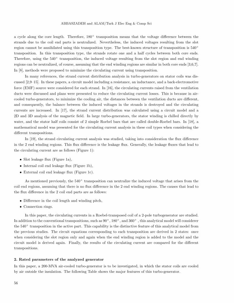
In [19], the strand circulating current analysis was studied, taking into consideration the flux difference
in the 2 end winding regions. This flux difference is the leakage flux. Generally, the leakage fluxes that lead to
the circulating current are as follows (Figure 1):
• Slot leakage flux (Figure 1a),
• Internal coil end leakage flux (Figure 1b),
• External coil end leakage flux (Figure 1c).
As mentioned previously, the 540 transposition can neutralize the induced voltage that arises from the
coil end regions, assuming that there is no flux difference in the 2 end winding regions. The causes that lead to
the flux difference in the 2 coil end parts are as follows:
• Difference in the coil length and winding pitch,
• Connection rings.
In this paper, the circulating currents in a Roebel-transposed coil of a 2-pole turbogenerator are studied.
In addition to the conventional transpositions, such as 90 , 180 , and 360 , this analytical model will considerer
the 540 transposition in the active part. This capability is the distinctive feature of this analytical model from
the previous studies. The circuit equations corresponding to each transposition are derived in 2 states: once
when considering the slot region only and again when the end winding region is added to the model and the
circuit model is derived again. Finally, the results of the circulating current are compared for the different
transpositions.
2. Rated parameters of the analyzed generator
In this paper, a 200-MVA air-cooled turbo-generator is to be investigated, in which the stator coils are cooled
by air outside the insulation. The following Table shows the major features of this turbo-generator.
56
ABBASZADEH and ALAM/Turk J Elec Eng & Comp Sci
strandleakage flux
Bv
Bt
a b c
Figure 1. The leakage fluxes that lead to the circulating current.
Table. Major features of the 200-MVA turbine generator.
Capacity 200 MVANumber of poles 2
Stator cooling system Indirect air coolingRotor cooling system Direct air cooling
Insulation Class F
Speed 3000 min−1
Number of stator slots 60Stator winding Y*3
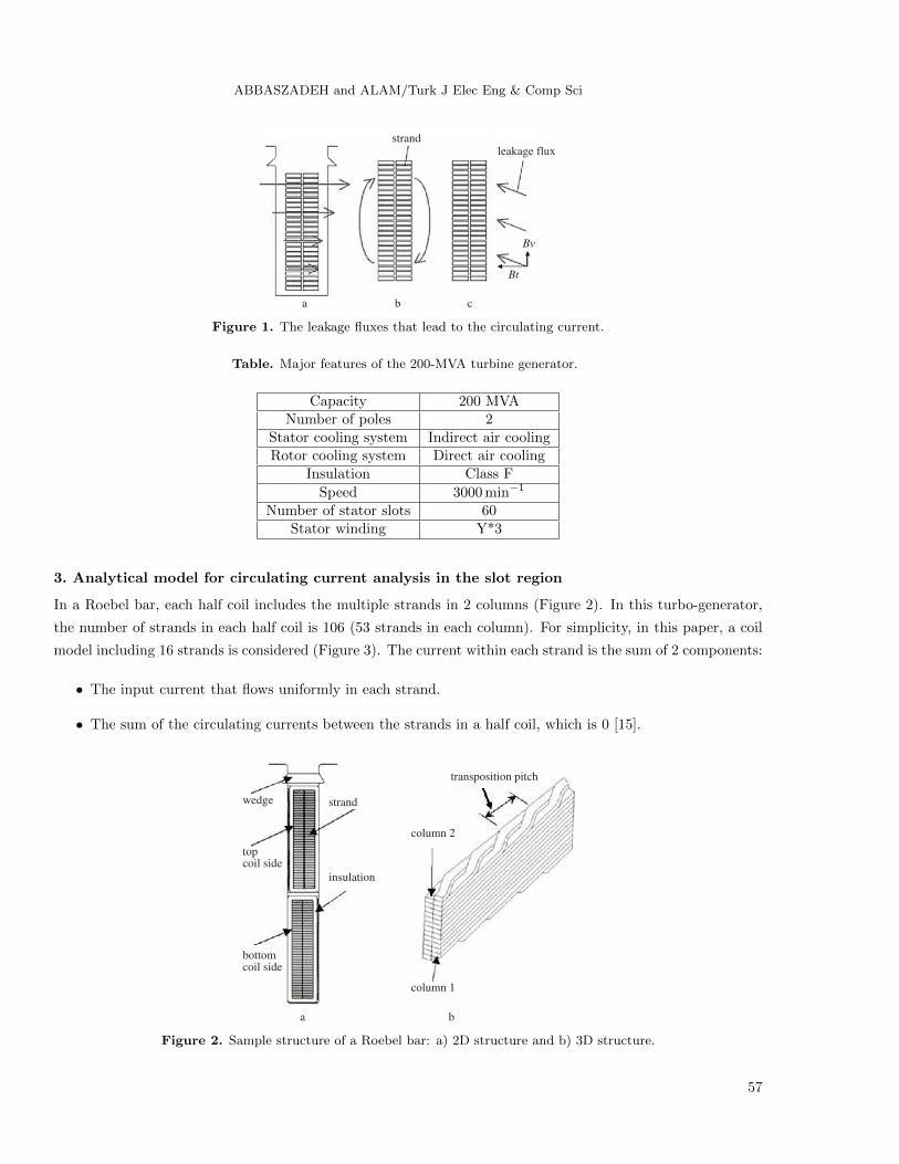
3. Analytical model for circulating current analysis in the slot region
In a Roebel bar, each half coil includes the multiple strands in 2 columns (Figure 2). In this turbo-generator,
the number of strands in each half coil is 106 (53 strands in each column). For simplicity, in this paper, a coil
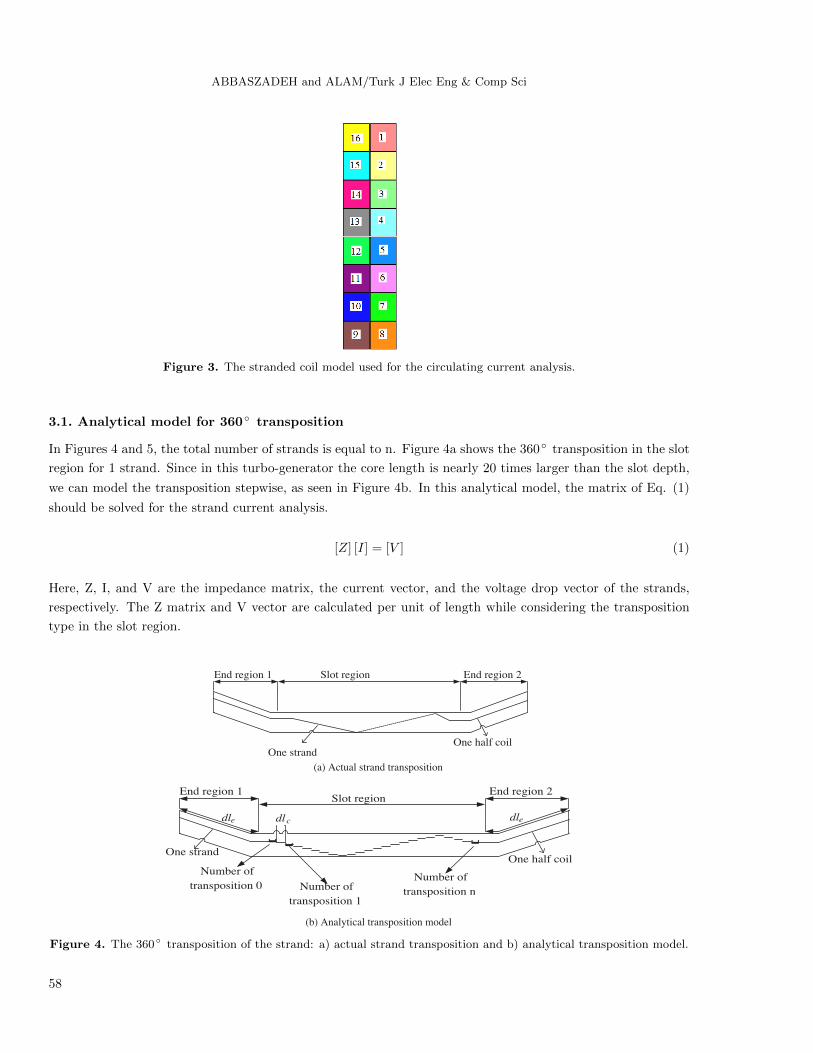
model including 16 strands is considered (Figure 3). The current within each strand is the sum of 2 components:
• The input current that flows uniformly in each strand.
• The sum of the circulating currents between the strands in a half coil, which is 0 [15].
topcoil side
wedge
bottomcoil side
insulation
strand
column 2
transposition pitch
column 1
a b
Figure 2. Sample structure of a Roebel bar: a) 2D structure and b) 3D structure.
57
ABBASZADEH and ALAM/Turk J Elec Eng & Comp Sci
Figure 3. The stranded coil model used for the circulating current analysis.
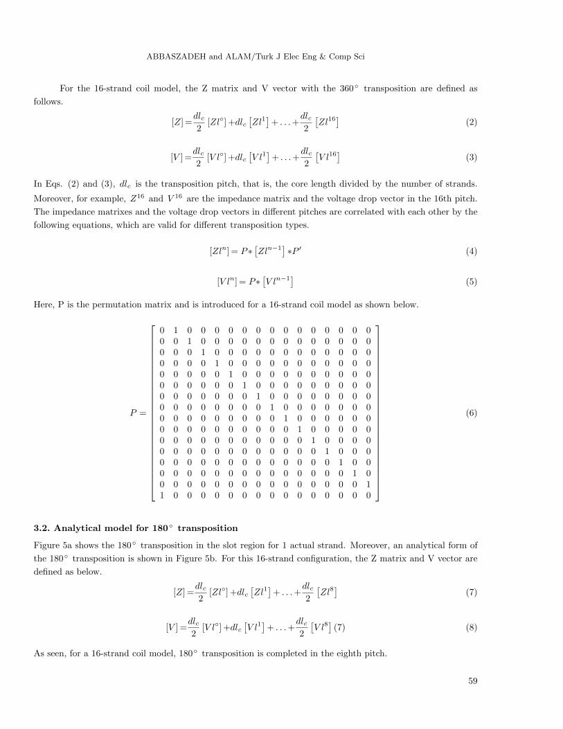
3.1. Analytical model for 360 transposition
In Figures 4 and 5, the total number of strands is equal to n. Figure 4a shows the 360 transposition in the slot
region for 1 strand. Since in this turbo-generator the core length is nearly 20 times larger than the slot depth,
we can model the transposition stepwise, as seen in Figure 4b. In this analytical model, the matrix of Eq. (1)
should be solved for the strand current analysis.
[Z] [I] = [V ] (1)
Here, Z, I, and V are the impedance matrix, the current vector, and the voltage drop vector of the strands,
respectively. The Z matrix and V vector are calculated per unit of length while considering the transposition
type in the slot region.
One strandOne half coil
End region 1 End region 2Slot region
(a) Actual strand transposition
One strandOne half coil
End region 1 End region 2Slot region
dle dlc
Number of
transposition 0
Number of
transposition 1
Number of
transposition n
dle
(b) Analytical transposition model
Figure 4. The 360 transposition of the strand: a) actual strand transposition and b) analytical transposition model.
58
ABBASZADEH and ALAM/Turk J Elec Eng & Comp Sci
For the 16-strand coil model, the Z matrix and V vector with the 360 transposition are defined as
follows.
[Z] =dlc2
[Zl] +dlc[Zl1]
+ . . .+dlc2
[Zl16
](2)
[V ] =dlc2
[V l] +dlc[V l1]
+ . . .+dlc2
[V l16
](3)
In Eqs. (2) and (3), dlc is the transposition pitch, that is, the core length divided by the number of strands.
Moreover, for example, Z16 and V 16 are the impedance matrix and the voltage drop vector in the 16th pitch.
The impedance matrixes and the voltage drop vectors in different pitches are correlated with each other by the
following equations, which are valid for different transposition types.
[Zln] = P∗[Zln−1
]∗P ′ (4)
[V ln] = P∗[V ln−1
](5)
Here, P is the permutation matrix and is introduced for a 16-strand coil model as shown below.
P =
0 1 0 0 0 0 0 0 0 0 0 0 0 0 0 00 0 1 0 0 0 0 0 0 0 0 0 0 0 0 00 0 0 1 0 0 0 0 0 0 0 0 0 0 0 00 0 0 0 1 0 0 0 0 0 0 0 0 0 0 00 0 0 0 0 1 0 0 0 0 0 0 0 0 0 00 0 0 0 0 0 1 0 0 0 0 0 0 0 0 00 0 0 0 0 0 0 1 0 0 0 0 0 0 0 00 0 0 0 0 0 0 0 1 0 0 0 0 0 0 00 0 0 0 0 0 0 0 0 1 0 0 0 0 0 00 0 0 0 0 0 0 0 0 0 1 0 0 0 0 00 0 0 0 0 0 0 0 0 0 0 1 0 0 0 00 0 0 0 0 0 0 0 0 0 0 0 1 0 0 00 0 0 0 0 0 0 0 0 0 0 0 0 1 0 00 0 0 0 0 0 0 0 0 0 0 0 0 0 1 00 0 0 0 0 0 0 0 0 0 0 0 0 0 0 11 0 0 0 0 0 0 0 0 0 0 0 0 0 0 0
(6)
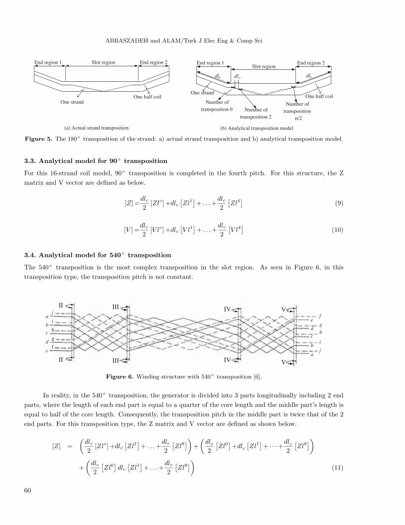
3.2. Analytical model for 180 transposition
Figure 5a shows the 180 transposition in the slot region for 1 actual strand. Moreover, an analytical form of
the 180 transposition is shown in Figure 5b. For this 16-strand configuration, the Z matrix and V vector are
defined as below.
[Z] =dlc2
[Zl] +dlc[Zl1]
+ . . .+dlc2
[Zl8]
(7)
[V ] =dlc2
[V l] +dlc[V l1]
+ . . .+dlc2
[V l8]
(7) (8)
As seen, for a 16-strand coil model, 180 transposition is completed in the eighth pitch.
59
ABBASZADEH and ALAM/Turk J Elec Eng & Comp Sci
One strandOne half coil
End region 1 End region 2Slot region
(a) Actual strand transposition
One strandOne half coil
End region 1 End region 2Slot region
dle dlc
Number of
transposition 0
Number of
transposition 2
Number of
transposition
n/2
dle
(b) Analytical transposition model
Figure 5. The 180 transposition of the strand: a) actual strand transposition and b) analytical transposition model.
3.3. Analytical model for 90 transposition
For this 16-strand coil model, 90 transposition is completed in the fourth pitch. For this structure, the Z
matrix and V vector are defined as below.
[Z] =dlc2
[Zl] +dlc[Zl1]
+ . . .+dlc2
[Zl4]
(9)
[V ] =dlc2
[V l] +dlc[V l1]
+ . . .+dlc2
[V l4]
(10)
3.4. Analytical model for 540 transposition
The 540 transposition is the most complex transposition in the slot region. As seen in Figure 6, in this
transposition type, the transposition pitch is not constant.
a
b
c
d
e
j
i
h
g
f
II
II
III
III
IV
IV
V
V
f
g
h
i
j
e
d
c
b
a
Figure 6. Winding structure with 540 transposition [6].
In reality, in the 540 transposition, the generator is divided into 3 parts longitudinally including 2 end
parts, where the length of each end part is equal to a quarter of the core length and the middle part’s length is
equal to half of the core length. Consequently, the transposition pitch in the middle part is twice that of the 2
end parts. For this transposition type, the Z matrix and V vector are defined as shown below.
[Z] =
(dlc2
[Zl] +dlc[Zl1]
+ . . .+dlc2
[Zl8])
+
(dlc2
[Zl0]
+dlc[Zl1]
+ · · ·+dlc2
[Zl8])
+
(dlc2
[Zl0]dlc[Zl1]
+ . . .+dlc2
[Zl8])
(11)
60
ABBASZADEH and ALAM/Turk J Elec Eng & Comp Sci
[V ] =
(dlc2
[V l0]
+dlc[V l1]
+ . . .+dlc2
[V l8])
+
(dlc2
[V l0]
+dlc[V l1]
+ · · ·+dlc2
[V l8])
+
(dlc2
[V l0]
+dlc[V l1]
+ . . .+dlc2
[V l8])
(12)
In Eqs. (10) and (11), dlc= 2×dlc .
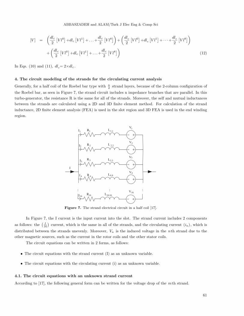
4. The circuit modeling of the strands for the circulating current analysis
Generally, for a half coil of the Roebel bar type with n2 strand layers, because of the 2-column configuration of
the Roebel bar, as seen in Figure 7, the strand circuit includes n impedance branches that are parallel. In this
turbo-generator, the resistance R is the same for all of the strands. Moreover, the self and mutual inductances
between the strands are calculated using a 2D and 3D finite element method. For calculation of the strand
inductance, 2D finite element analysis (FEA) is used in the slot region and 3D FEA is used in the end winding
region.
3R 3,3L3V
4R 4,4L4V
1R 1,1L1V
2R 2,2L2V
...
16R 16,16L16V
......
1I
2I
3I
4I
16I
I
Figure 7. The strand electrical circuit in a half coil [17].
In Figure 7, the I current is the input current into the slot. The strand current includes 2 components
as follows: the(
I16
)current, which is the same in all of the strands, and the circulating current (in), which is
distributed between the strands unevenly. Moreover, Vn is the induced voltage in the nth strand due to the
other magnetic sources, such as the current in the rotor coils and the other stator coils.
The circuit equations can be written in 2 forms, as follows:
• The circuit equations with the strand current (I) as an unknown variable.
• The circuit equations with the circulating current (i) as an unknown variable.
4.1. The circuit equations with an unknown strand current
According to [17], the following general form can be written for the voltage drop of the mth strand.
61
ABBASZADEH and ALAM/Turk J Elec Eng & Comp Sci
Vm= R(im+I/16
)+jω
16∑k=1
Lm,k
(ik+I/16
)(13)
Since in this turbo-generator, all of the strands are short-circuited in the 2 ends of the half coil, the following
general equation can be concluded for the mth strand.
Vm−V = −jω∅ex,m (14)
In Eq. (13), V is the unknown voltage along the half coil in the slot region. In this unknown voltage (V), the
influence of the external flux is not considered. Moreover, ∅ex,m is the magnetic flux in the mth strand due to
the other magnetic sources. When substituting Eq. (12) in Eq. (13), the following equation is obtained.
R(im+I/16
)+jω
16∑k=1
Lm,k
(ik+I/16
)−V = −jω∅ex,m (15)
As is known, the strand current (Im) and circulating current (im) are correlated with each other as follows.
Im = im + I/16 (16)
According to the current conservation law, the sum of all of the strand currents is equal to the input current
into a layer of the slot, as follows.
16∑m=1
Im = I (17)
When replacing Eq. (15) in Eq. (14), the following general equation is achieved in terms of the k th strand
current.
RIk+jω
16∑m=1
Lk,mIm−V = −jω∅ex,k (18)
Therefore, when considering the strand current as an unknown variable, the equation system that should be
solved is in the following form.
RI1+jω16∑
m=1L1,mIm−V = −jω∅ex,1
RI2+jω16∑
m=1L2,mIm−V = −jω∅ex,2
...
RI15+jω16∑
m=1L15,mIm−V = −jω∅ex,15
RI16+jω16∑
m=1L16,mIm−V = −jω∅ex,16∑16
m=1 Im= I
(19)
62
ABBASZADEH and ALAM/Turk J Elec Eng & Comp Sci
4.2. Circuit equations with an unknown circulating current between the strands
For achieving the equation system with the circulating current between the strands (ik) as an unknown variable,
it is sufficient that in Eq. (14), the ohmic and inductive voltages drop due to the current I16 [known parts in
Eq. (14)] transferring into the right-hand side of the equation, as follows.
Rik+jω∑16
m=1Lk,mim−V = −jω∅exk−R
I
16−jω
∑16
m=1Lk,m
I
16(20)
As seen in the obtained equation, the circulating current (ik) is an unknown variable. The inductive voltage
drop due to I16 is called the internal flux and is defined as follows.
∅in,k=∑16
m=1Lk,m
I
16(21)
When substituting Eq. (20) into Eq. (19), the following general equation is achieved in terms of the circulating
current in the k th strand (ik).
Rik+jω∑16
m=1Lk,mim−V = −jω (∅ex,k+∅in,k)−R I
16(22)
As is known, according to the current conservation law, the sum of the circulating currents between the strands
is 0, as below. ∑16
m=1im = 0 (23)
Therefore, when considering the circulating current between the strands as an unknown variable, the following
equation system is obtained.
Ri1+jω∑16
m=1L1,mim−V = −jω (∅ex,1+∅in.1)−R I
16
Ri2+jω∑16
m=1L2,mim−V = −jω (∅ex,2+∅in.2)−R I
16...
Ri15+jω∑16
m=1L15,mim−V = −jω (∅ex,15+∅in.15)−R I
16
Ri16+jω∑16
m=1L16,mim−V = −jω (∅ex,16+∅in.16)−R I
16∑16
m=1im= 0
(24)
4.3. Unknown selection in the circuit equations
In order to select the strand current or the circulating current as an unknown variable, in this part, the equation
systems presented in Eqs. (18) and (23) are compared with one another. As is seen, the left-hand sides of the
system for Eqs. (18) and (23) are similar. However, on the right-hand side of Eq. (18), there is an external
flux only, whereas on the right-hand side of Eq. (23), there is a total linkage flux. Since our access to the total
linkage flux is more comfortable through FEA, the equation system presented in Eq. (23) is selected for the
63
ABBASZADEH and ALAM/Turk J Elec Eng & Comp Sci
circulating current analysis; that is, the circulating current is selected as an unknown variable. The matrix form
of the equation system in Eq. (23) is presented in Eq. (26). λk and U in Eq. (26), are defined as follows.
λk=∅in,k+∅ex,k (25)
RI
n= U (26)
Therefore, the circulating current between the strands can be calculated using Eq. (27).
Z1,1
Z2,1
Z1,2
Z2,2· · · Z1,16
Z2,16
−1−1
.... . .
...Z16,1
1Z16,2
1· · · Z16,16
1−10
i1i2...i16
V
=
−jωλ1−U−jωλ2−U...−jωλ16−U0
(27)
i1i2...i16
V
=
Z1,1
Z2,1
Z1,2
Z2,2· · · Z1,16
Z2,16
−1−1
.... . .
...Z16,1
1Z16,2
1· · · Z16,16
1−10
−1
−jωλ1−U−jωλ2−U...−jωλ16−U0
(28)
In Eq. (27), the Z matrix and V vector are defined as follows.
Z =
Z1,1
Z2,1
Z1,2
Z2,2· · · Z1,16
Z2,16
.... . .
...Z16,1 Z16,2 · · · Z16,16
=
R+ jωL1,1
jωL2,1
jωL1,2
R+ jωL2,2· · · jωL1,16
jωL2,16
.... . .
...jωL16,1 jωL16,2 · · · R+ jωL16,16
(29)
V =
−jωλ1−U−jωλ2−U...−jωλ16−U
(30)
Here, R is the magnitude of the strand resistance in the slot region, and in this turbo-generator, it is equal to
165.42 nΩmm . ω is the angular frequency and is defined as follows.
ω = 2πf (30)
Here f is the electrical frequency and is equal to 50 Hz. For calculation of the Z matrix and V vector in different
transposition pitches, the permutation matrix [defined in Eq. (6)] is applied to the Z matrix and V vector in
the first transposition pitch, as follows.
Zlk=pk(Zl0) (p
′)k
(31)
V lk=pk(V l0)
(32)
64
ABBASZADEH and ALAM/Turk J Elec Eng & Comp Sci
5. Circuit modeling with the half coil
In this turbo-generator, the winding configuration is such that the strands are short-circuited in 2 core ends (in
and out of the slot region) and in the half coil end. Therefore, in addition to the slot region, the effect of the end
winding region should be considered in circuit equations. It should be noted that in this turbo-generator, there
is no transposition in the end winding region. Of course, the transposition styles in the end winding region and
slot region are different.
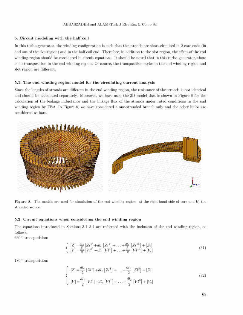
5.1. The end winding region model for the circulating current analysis
Since the lengths of strands are different in the end winding region, the resistance of the strands is not identical
and should be calculated separately. Moreover, we have used the 3D model that is shown in Figure 8 for the
calculation of the leakage inductance and the linkage flux of the strands under rated conditions in the end
winding region by FEA. In Figure 8, we have considered a one-stranded branch only and the other limbs are
considered as bars.
Figure 8. The models are used for simulation of the end winding region: a) the right-hand side of core and b) the
stranded section.
5.2. Circuit equations when considering the end winding region
The equations introduced in Sections 3.1–3.4 are reformed with the inclusion of the end winding region, as
follows.
360 transposition: [Z] =dlc
2 [Zl] +dlc[Zl1]
+ . . .+dlc2
[Zl16
]+ [Ze]
[V ] =dlc2 [V l] +dlc
[V l1]
+ . . .+dlc2
[V l16
]+ [Ve]
(31)
180 transposition: [Z] =
dlc2
[Zl] +dlc[Zl1]
+ . . .+dlc2
[Zl8]
+ [Ze]
[V ] =dlc2
[V l] +dlc[V l1]
+ . . .+dlc2
[V l8]
+ [Ve]
(32)
65
ABBASZADEH and ALAM/Turk J Elec Eng & Comp Sci
90 transposition: [Z] =
dlc2
[Zl] +dlc[Zl1]
+ . . .+dlc2
[Zl4]
+ [Ze]
[V ] =dlc2
[V l] +dlc[V l1]
+ . . .+dlc2
[V l4]
+ [Ve]
(33)
540 transposition:
[Z] =
(dlc2
[Zl] +dlc[Zl1]
+ . . .+dlc2
[Zl8])
+
(dlc2
[Zl] +dlc[Zl1]
+ · · ·+dlc2
[Zl8])
+
(dlc2
[Zl] +dlc[Zl1]
+ . . .+dlc2
[Zl8])
+ [Ze](34)
[V ] =
(dlc2
[V l] +dlc[V l1]
+ . . .+dlc2
[V l8])
+
(dlc2
[V l] +dlc[V l1]
+ · · ·+dlc2
[V l8])
+
(dlc2
[V l] +dlc[V l1]
+ . . .+dlc2
[V l8])
+ [Ve]
5.3. Circulating current analysis in the slot region using the analytical model
As previously stated, the linkage flux of the strands is calculated under rated conditions. In this condition, the
strand current can be calculated as follows.
I =
(10368/2
)16
= 324A
It should be noted that in this turbo-generator, the rated current of each phase is 10,368 A and the phase
winding is double-layer.
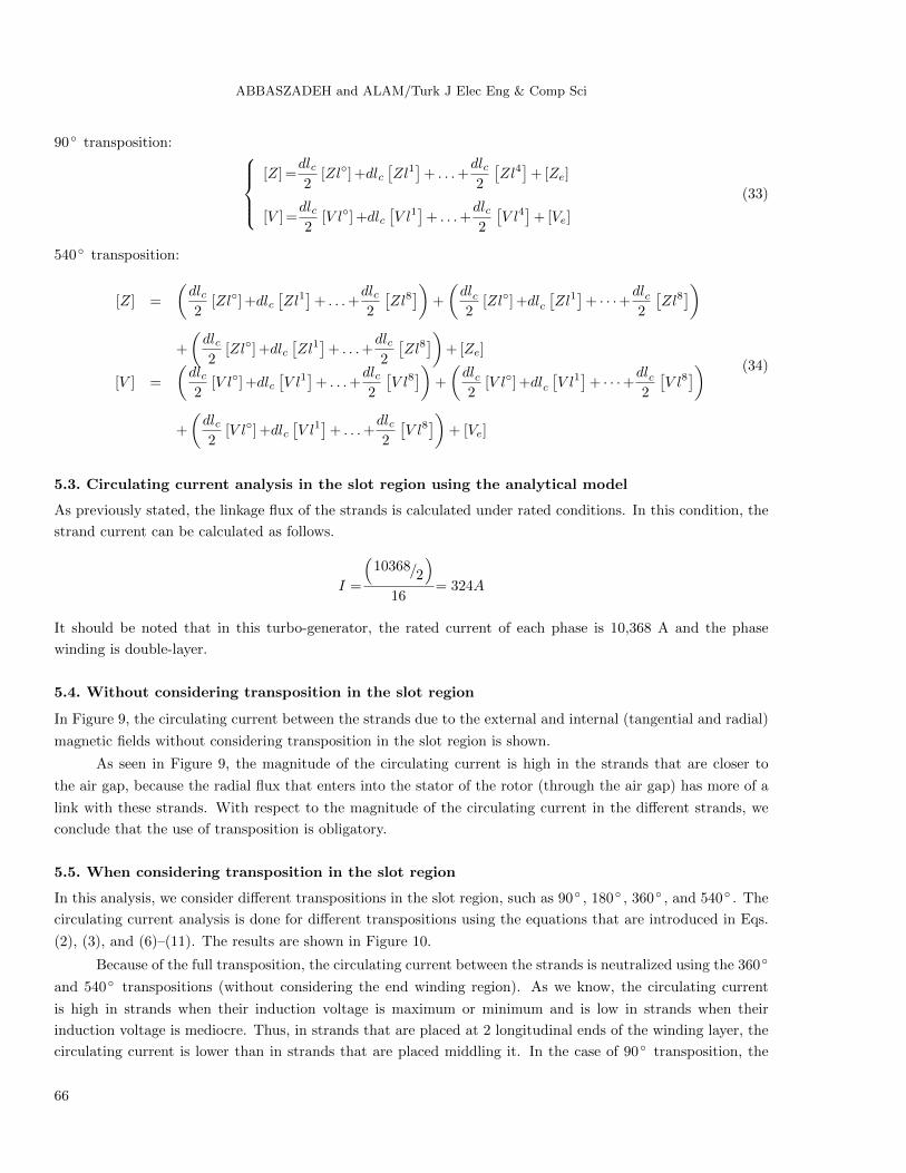
5.4. Without considering transposition in the slot region
In Figure 9, the circulating current between the strands due to the external and internal (tangential and radial)
magnetic fields without considering transposition in the slot region is shown.
As seen in Figure 9, the magnitude of the circulating current is high in the strands that are closer to
the air gap, because the radial flux that enters into the stator of the rotor (through the air gap) has more of a
link with these strands. With respect to the magnitude of the circulating current in the different strands, we
conclude that the use of transposition is obligatory.
5.5. When considering transposition in the slot region
In this analysis, we consider different transpositions in the slot region, such as 90 , 180 , 360 , and 540 . The
circulating current analysis is done for different transpositions using the equations that are introduced in Eqs.
(2), (3), and (6)–(11). The results are shown in Figure 10.
Because of the full transposition, the circulating current between the strands is neutralized using the 360
and 540 transpositions (without considering the end winding region). As we know, the circulating current
is high in strands when their induction voltage is maximum or minimum and is low in strands when their
induction voltage is mediocre. Thus, in strands that are placed at 2 longitudinal ends of the winding layer, the
circulating current is lower than in strands that are placed middling it. In the case of 90 transposition, the
66
ABBASZADEH and ALAM/Turk J Elec Eng & Comp Sci
circulating current is maximum in strand No. 6 because the transposition route of this strand is close to the air
gap. Moreover, the flux linkage with strands No. 6 and No. 14 is maximum and minimum, respectively, when
the 180 transposition is used; thus, the magnitude of the circulating current is high in these strands.
2 4 6 8 10 12 14 160
500
1000
1500
2000
2500
3000
3500
Strand number
Cir
cula
ting c
urr
ent
(A)
2 4 6 8 10 12 14 160
200
400
600
800
1000
1200
1400
1600
1800
2000
Strand number
Cir
cula
ting c
urr
ent
(A)
360°180°90°540°
Figure 9. Circulating current between the strands with-
out considering transposition in the slot region.
Figure 10. The magnitude of the circulating current
when considering different transpositions.
6. Circulating current analysis in the half coil using the analytical model
In this new analysis, the end winding region is added to the slot region. To perform this analysis, the presented
equations in Section 5.2 are used. The end winding region model is shown in Figure 8.
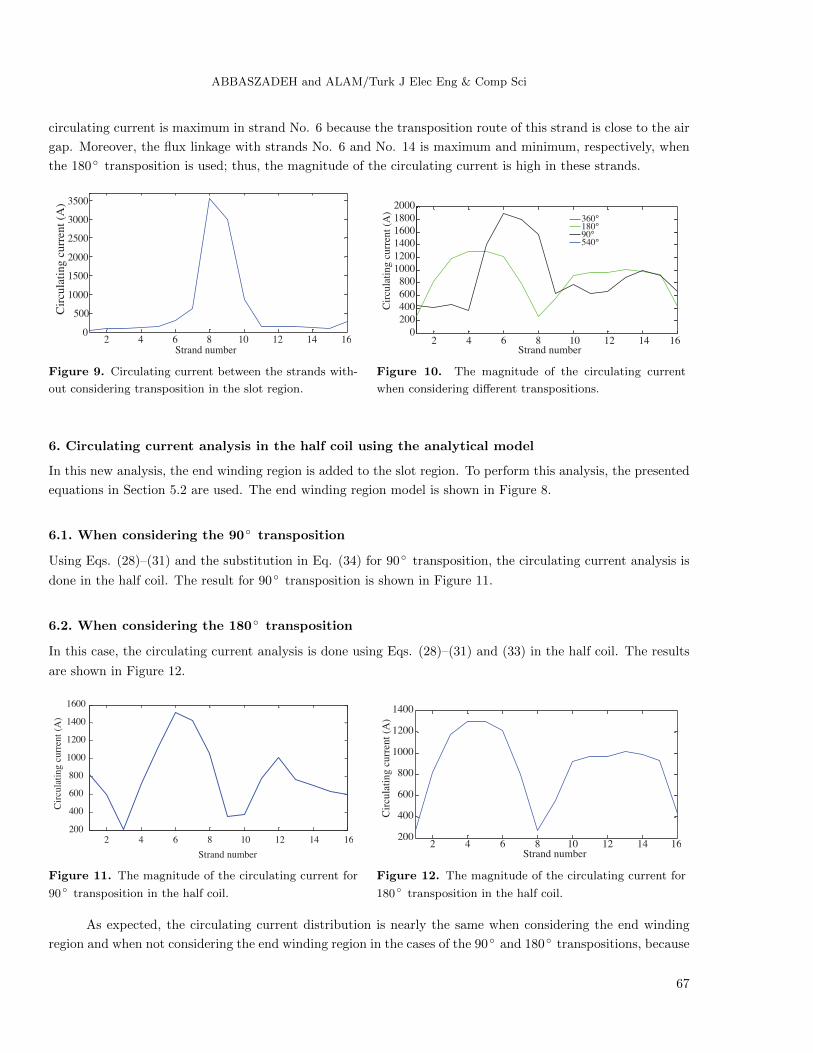
6.1. When considering the 90 transposition
Using Eqs. (28)–(31) and the substitution in Eq. (34) for 90 transposition, the circulating current analysis is
done in the half coil. The result for 90 transposition is shown in Figure 11.
6.2. When considering the 180 transposition
In this case, the circulating current analysis is done using Eqs. (28)–(31) and (33) in the half coil. The results
are shown in Figure 12.
2 4 6 8 10 12 14 16200
400
600
800
1000
1200
1400
1600
Strand number
Cir
cula
ting c
urr
ent
(A)
2 4 6 8 10 12 14 16200
400
600
800
1000
1200
1400
Strand number
Cir
cula
ting c
urr
ent
(A)
Figure 11. The magnitude of the circulating current for
90 transposition in the half coil.
Figure 12. The magnitude of the circulating current for
180 transposition in the half coil.
As expected, the circulating current distribution is nearly the same when considering the end winding
region and when not considering the end winding region in the cases of the 90 and 180 transpositions, because
67
ABBASZADEH and ALAM/Turk J Elec Eng & Comp Sci
the influence of the slot region is dominant in the creation of the circulating current between the strands using
these transposition types.
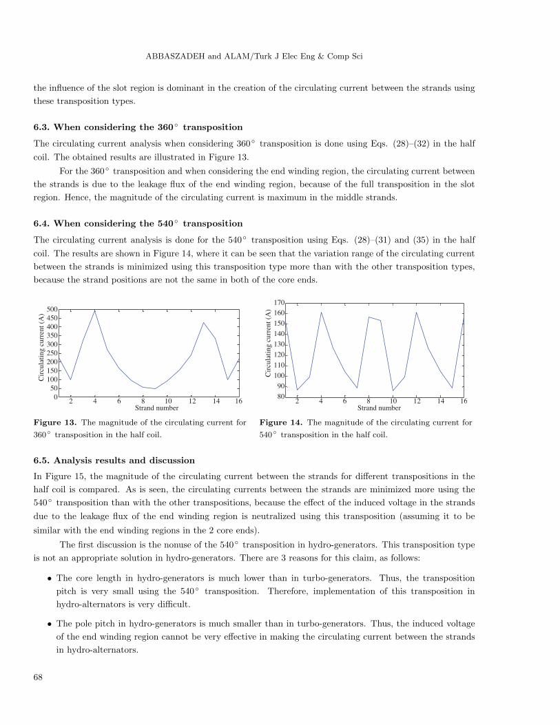
6.3. When considering the 360 transposition
The circulating current analysis when considering 360 transposition is done using Eqs. (28)–(32) in the half
coil. The obtained results are illustrated in Figure 13.
For the 360 transposition and when considering the end winding region, the circulating current between
the strands is due to the leakage flux of the end winding region, because of the full transposition in the slot
region. Hence, the magnitude of the circulating current is maximum in the middle strands.
6.4. When considering the 540 transposition
The circulating current analysis is done for the 540 transposition using Eqs. (28)–(31) and (35) in the half
coil. The results are shown in Figure 14, where it can be seen that the variation range of the circulating current
between the strands is minimized using this transposition type more than with the other transposition types,
because the strand positions are not the same in both of the core ends.
2 4 6 8 10 12 14 160
50
100
150
200
250
300
350
400
450
500
Strand number
Cir
cula
ting c
urr
ent
(A)
2 4 6 8 10 12 14 1680
90
100
110
120
130
140
150
160
170
Strand number
Cir
cula
tin
g c
urr
ent
(A)
Figure 13. The magnitude of the circulating current for
360 transposition in the half coil.
Figure 14. The magnitude of the circulating current for
540 transposition in the half coil.
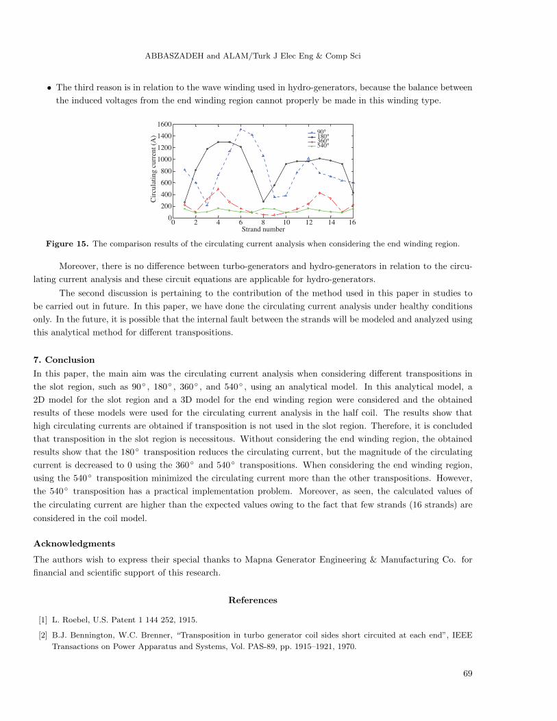
6.5. Analysis results and discussion
In Figure 15, the magnitude of the circulating current between the strands for different transpositions in the
half coil is compared. As is seen, the circulating currents between the strands are minimized more using the
540 transposition than with the other transpositions, because the effect of the induced voltage in the strands
due to the leakage flux of the end winding region is neutralized using this transposition (assuming it to be
similar with the end winding regions in the 2 core ends).
The first discussion is the nonuse of the 540 transposition in hydro-generators. This transposition type
is not an appropriate solution in hydro-generators. There are 3 reasons for this claim, as follows:
• The core length in hydro-generators is much lower than in turbo-generators. Thus, the transposition
pitch is very small using the 540 transposition. Therefore, implementation of this transposition in
hydro-alternators is very difficult.
• The pole pitch in hydro-generators is much smaller than in turbo-generators. Thus, the induced voltage
of the end winding region cannot be very effective in making the circulating current between the strands
in hydro-alternators.
68
ABBASZADEH and ALAM/Turk J Elec Eng & Comp Sci
• The third reason is in relation to the wave winding used in hydro-generators, because the balance between
the induced voltages from the end winding region cannot properly be made in this winding type.
0 2 4 6 8 10 12 14 160
200
400
600
800
1000
1200
1400
1600
Strand number
Cir
cula
ting c
urr
ent
(A)
90°180°360°540°
Figure 15. The comparison results of the circulating current analysis when considering the end winding region.
Moreover, there is no difference between turbo-generators and hydro-generators in relation to the circu-
lating current analysis and these circuit equations are applicable for hydro-generators.
The second discussion is pertaining to the contribution of the method used in this paper in studies to
be carried out in future. In this paper, we have done the circulating current analysis under healthy conditions
only. In the future, it is possible that the internal fault between the strands will be modeled and analyzed using
this analytical method for different transpositions.
7. Conclusion
In this paper, the main aim was the circulating current analysis when considering different transpositions in
the slot region, such as 90 , 180 , 360 , and 540 , using an analytical model. In this analytical model, a
2D model for the slot region and a 3D model for the end winding region were considered and the obtained
results of these models were used for the circulating current analysis in the half coil. The results show that
high circulating currents are obtained if transposition is not used in the slot region. Therefore, it is concluded
that transposition in the slot region is necessitous. Without considering the end winding region, the obtained
results show that the 180 transposition reduces the circulating current, but the magnitude of the circulating
current is decreased to 0 using the 360 and 540 transpositions. When considering the end winding region,
using the 540 transposition minimized the circulating current more than the other transpositions. However,
the 540 transposition has a practical implementation problem. Moreover, as seen, the calculated values of
the circulating current are higher than the expected values owing to the fact that few strands (16 strands) are
considered in the coil model.
Acknowledgments
The authors wish to express their special thanks to Mapna Generator Engineering & Manufacturing Co. for
financial and scientific support of this research.
References
[1] L. Roebel, U.S. Patent 1 144 252, 1915.
[2] B.J. Bennington, W.C. Brenner, “Transposition in turbo generator coil sides short circuited at each end”, IEEE
Transactions on Power Apparatus and Systems, Vol. PAS-89, pp. 1915–1921, 1970.
69

ABBASZADEH and ALAM/Turk J Elec Eng & Comp Sci
[3] G.W. Staats, Stator Coil Transposition, United States Patent Office, Serial No. 644,344, Application 6 March 1957.
[4] H. Kasten, W. Hofmann, “Optimal number of strands in electrical medium-frequency machines”, International
Conference on Electrical Machines, pp. 1–6, 2010.
[5] P.B. Reddy, T.M. Jahns, “Analysis of bundle losses in high speed machines”, International Conference on Power
Electronics, pp. 2181–2188, 2010.
[6] W.L. Ringland, Strand Transposition, United States Patent Office, patented 28 January 1958.
[7] W.L. Ringland, L.T. Rosenberg, “A new stator coil transposition for large machines”, Transactions of the American
Institute of Electrical Engineers, Part 3, Power Apparatus and Systems, Vol. 78, pp. 743–746, 1959.
[8] P.R. Heller, W.C. Brenner, H.M. Philossky, “Transposed conductor for dynamoelectric machines”, U.S. Patent 3
647 932, 1972.
[9] T. Saitoh, M. Satoh, N. Takahashi, “An analysis of strand current distribution in turbine-generator stator coils”,
Transactions IEE Japan, Vol. 105-B, pp. 249–256, 1985.
[10] M. Iseli, K. Reichert, G. Neidhofer, “End region field and circulating currents in Roebel bars”, International
Conference on Electrical Machines, Vol. 2, pp. 718–723, 1990.
[11] T. Renyuan, X. Guangren, T. Lijian, Z. Danqun, “Calculation of end region magnetic field and circulating losses
for turbo-generators using a coupled field and circuit equations method”, IEEE Transactions on Magnetics, Vol.
26, pp. 497–500, 1990.
[12] T. Tokumasu, Y. Kabata, H. Nakamura, M. Kaki-uchi, “Circulating current analysis of turbine generator stator
coil considering ventilation ducts”, IEE Japan, Vol. RM-04(125–150), pp. 83–88, 2004.
[13] K. Ide, K. Takahashi, K. Hattori, N. Motoi, K. Furukawa, T. Watanabe, “Practical calculation method of circulating
current loss for large turbine generator designs”, Transactions of the Institute of Electrical Engineers of Japan, Vol.
123, pp. 554–560, 2003.
[14] D.C. MacDonald, “Losses in Roebel bars: effect of slot portion on circulating currents”, Proceedings of the
Institution of Electrical Engineers, Vol. 117, pp. 111–118, 1970.
[15] D.C. MacDonald, “Circulating current loss within Roebel-bar stator windings in hydroelectric alternators”, Pro-
ceedings of the Institution of Electrical Engineers, Vol. 118, pp. 689–697, 1971.
[16] M. Fujita, Y. Kabata, T. Tokumasu, M. Kakiuchi, H. Shiomi, S. Nagano, “Air-cooled large turbine generator with
multiple pitched ventilation ducts”, IEEE International Conference on International Electric Machines and Drives,
pp. 910–917, 2005.
[17] K. Takahashi, M. Takahashi, M. Sato, “Calculation method for strand current distributions in armature windings
of a turbine generator”, Electrical Engineering in Japan, Vol. 143, pp. 50–58, 2003.
[18] J. Haldemann, “Transposition in stator bars of large turbogenerators”, IEEE Transactions on Energy Conversion,
Vol. 19, pp. 553–560, 2004.
[19] M. Fujita, Y. Kabata, T. Tokumasu, K. Nagakura, M. Kakiuchi, S. Nagano, “Circulating currents in stator coils
of large turbine generators and loss reduction”, IEEE Transactions on Industry Applications, Vol. 45, pp. 685–693,
2009.
70