Embed Size (px)
Citation preview

Series HRGC
Makes cooling water easily available, anytime, anywhere.Makes cooling water easily available, anytime, anywhere.
Cooling capacity (50 Hz):0.9 kW/1.9 kW/4.5 kW (Air-cooled refrigeration/Water-cooled refrigeration)
Temperature stability: ±1°C (Refrigerator ON/OFF control) / ±0.5°C (Proportional valve PID control)
Temperature range setting: 5 to 35°C
With ground fault circuit interrupter
With communications function (RS-485)
With communications function (RS-232C)
With water leakage sensor
With heater
With automatic water supply function
With external switch inlet
Stainless steel wetted part for circulating fluid
High-lift pump
With DI control kit
Dustproof filter set
By-pass piping set
DI (Deionised water) filter
Insulating material for DI (Deionised water) filter
Op
tio
ns
Op
tio
nal
acce
sso
ries
NEWNEWNewly added function
Circulating Fluid Temperature Controller
Refrigerated Thermo-cooler
Worldwide in voltage: Single phase 200 to 230 VAC, 50/60 HzCompliant with standards: ,
Energy saving: Stop-idling function (±1°C type)Automatic facility-water-saving function (water-cooled)
Environmentally friendly: RoHS compliant, Refrigerant R407CSelectable performance: Temperature stability ±1°C (Refrigerator ON/OFF control, ±0.5°C (Proportional valve PID control)
Easy installation: No need for facility water (air-cooled), Caster, by-pass valve and strainer (water-cooled), Stainless steel drain pan available as standard equipment, No need for power supply for remote operation
Easy maintenance: “Alarm code” display, Accessible from the front electric control panel
A variety of “Options” and “Optional Accessories” (Pages 9 to 14)
CAT.EUS40-51B-UK
Energy Saving and Environmentally Friendly
Selectable Performance
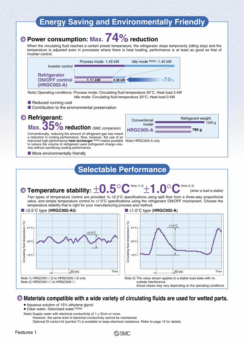
Power consumption: Max. 74% reductionWhen the circulating fluid reaches a certain preset temperature, the refrigerator stops temporarily (idling stop) and the temperature is adjusted even in processes where there is heat loading, performance is at least as good as that of inverter control.
±0.5°C type (HRGC002-A5)
Temperature stability: ±0.5°C Note 1) 3)±1.0°C Note 2) 3)
Two types of temperature control are provided: to ±0.5°C specifications using split flow from a three-way proportional valve, and simple temperature control to ±1.0°C specifications using the refrigerator ON/OFF mechanism. Choose the temperature stability that is right for your manufacturing process and method.
(when a load is stable)
±1.0°C type (HRGC002-A)
Note 3) The value shown applies to a stable load state with no outside interference.Actual values may vary depending on the operating conditions.
Note 1) HRGC001-5 to HRGC005-5 onlyNote 2) HRGC001- to HRGC005-
Inverter control
-74%
Circ
ulat
ing
fluid
tem
pera
ture
(°C
)
60 sec. Time
21°C
20°C
19°C
±0.5°C
Circ
ulat
ing
fluid
tem
pera
ture
(°C
)
60 sec. Time
21°C
20°C
19°C
±1.0°C
Materials compatible with a wide variety of circulating fluids are used for wetted parts. Aqueous solution of 15% ethylene glycol Clear water, Deionised water Note)
Note) Supply water with electrical conductivity of 1 µ S/cm or more. However, the same level of electrical conductivity cannot be maintained.Optional DI control kit (symbol Y) is available to keep electrical resistance. Refer to page 12 for details.
Process mode: 1.45 kW Idle mode Note): 1.45 kW
1.11 kW 0.38 kW0.38 kW1.11 kWRefrigeratorON/OFF control(HRGC002-A)
Reduced running cost Contribution to the environmental preservation
Note) Operating conditions: Process mode: Circulating fluid temperature 20°C, Heat load 2 kW Idle mode: Circulating fluid temperature 20°C, Heat load 0 kW
Refrigerant:
Max. 35% reduction (SMC comparison)
Conventionally, reducing the amount of refrigerant gas has meant a reduction in cooling performance. Now, however, the use of an improved high-performance heat exchanger Note) makes possible to reduce the volume of refrigerant used (refrigerant charge volu-me) without sacrificing cooling performance.
More environmentally friendly
Note) HRGC005-A only
780 g
1200 gConventional
model
Refrigerant weight
HRGC005-A
Features 1
Easy Installation and Maintenance
Air-Cooled Refrigeration Communications
Rotation
Adjuster Caster
Screw
Screw
Front panel
Front side
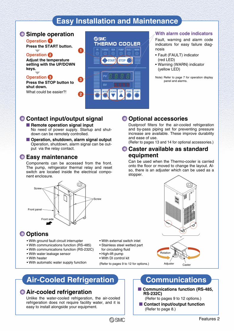
Simple operationOperationPress the START button.
OperationAdjust the temperature setting with the UP/DOWN keys.
OperationPress the STOP button to shut down.What could be easier?!
Optional accessoriesDustproof filters for the air-cooled refrigeration and by-pass piping set for preventing pressure increase are available. These improve durability and ease of use.(Refer to pages 13 and 14 for optional accessories.)
Easy maintenanceComponents can be accessed from the front. The pump, refrigerator thermal relay and reset switch are located inside the electrical compo-nent enclosure.
Communications function (RS-485, RS-232C)(Refer to pages 9 to 12 options.)
Contact input/output function(Refer to page 8.)
Air-cooled refrigerationUnlike the water-cooled refrigeration, the air-cooled refrigeration does not require facility water, and it is easy to install alongside your equipment.
With alarm code indicatorsFault, warning and alarm code indicators for easy failure diag-nosis
• Fault (FAULT) indicator(red LED)
• Warning (WARN) indicator(yellow LED)
Note) Refer to page 7 for operation display panel and alarms.
Contact input/output signal Remote operation signal input
No need of power supply. Startup and shut-down can be remotely controlled.
Operation, shutdown, alarm signal outputOperation, shutdown, alarm signal can be out-put via the relay contact. Caster available as standard
equipmentCan be used when the Thermo-cooler is carried onto the floor or moved to change the layout. Al-so, there is an adjuster which can be used as a stopper.
1
3
2
1
2
3
Options• With ground fault circuit interrupter• With communications function (RS-485)• With communications function (RS-232C)• With water leakage sensor• With heater• With automatic water supply function
• With external switch inlet• Stainless steel wetted part
for circulating fluid• High-lift pump• With DI control kit
(Refer to pages 9 to 12 for options.)
Features 2
Application Examples
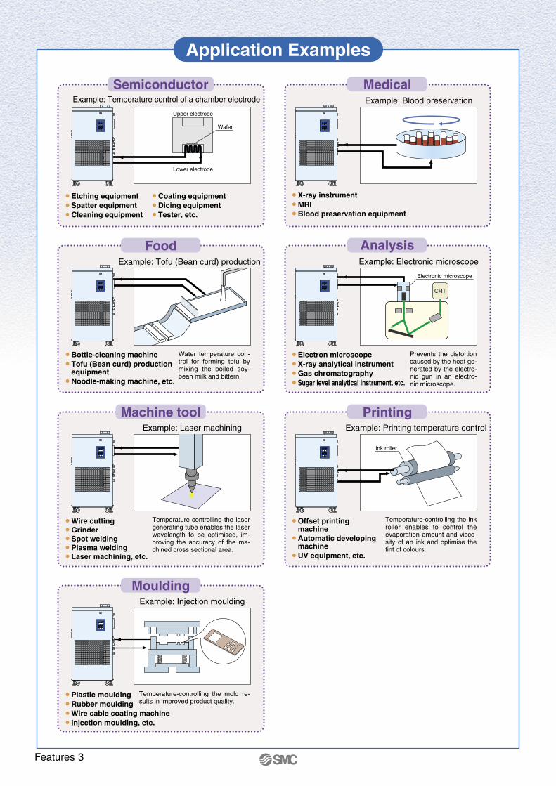
Example: Temperature control of a chamber electrode Example: Blood preservation
Example: Tofu (Bean curd) production Example: Electronic microscope
Example: Laser machining
Example: Injection moulding
Example: Printing temperature control
• Etching equipment• Spatter equipment• Cleaning equipment
• Coating equipment• Dicing equipment• Tester, etc.
• Bottle-cleaning machine• Tofu (Bean curd) production
equipment• Noodle-making machine, etc.
• Wire cutting• Grinder • Spot welding• Plasma welding• Laser machining, etc.
• X-ray instrument• MRI• Blood preservation equipment
• Electron microscope• X-ray analytical instrument• Gas chromatography• Sugar level analytical instrument, etc.
• Offset printing machine
• Automatic developing machine
• UV equipment, etc.
• Plastic moulding• Rubber moulding• Wire cable coating machine• Injection moulding, etc.
Temperature-controlling the ink roller enables to control the evaporation amount and visco-sity of an ink and optimise the tint of colours.
Prevents the distortion caused by the heat ge-nerated by the electro-nic gun in an electro-nic microscope.
Temperature-controlling the laser generating tube enables the laser wavelength to be optimised, im-proving the accuracy of the ma-chined cross sectional area.
Temperature-controlling the mold re-sults in improved product quality.
Water temperature con-trol for forming tofu by mixing the boiled soy-bean milk and bittern
Ink roller
Upper electrode
Lower electrode
Electronic microscope
CRT
Wafer
Semiconductor Medical
Food
Machine tool
Moulding
Analysis
Printing
Features 3
Construction and Principles
Ball tap
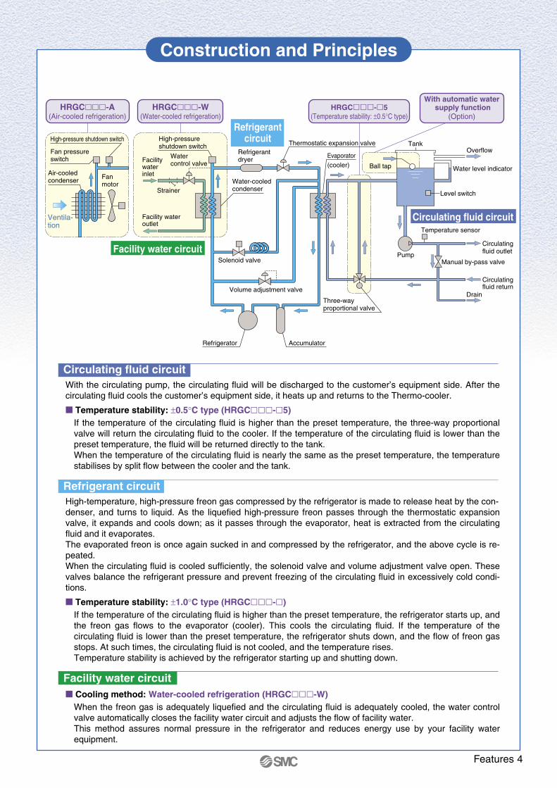
Circulating fluid circuitWith the circulating pump, the circulating fluid will be discharged to the customer’s equipment side. After the circulating fluid cools the customer’s equipment side, it heats up and returns to the Thermo-cooler.
Temperature stability: ±0.5°C type (HRGC-5)If the temperature of the circulating fluid is higher than the preset temperature, the three-way proportional valve will return the circulating fluid to the cooler. If the temperature of the circulating fluid is lower than the preset temperature, the fluid will be returned directly to the tank.When the temperature of the circulating fluid is nearly the same as the preset temperature, the temperature stabilises by split flow between the cooler and the tank.
Refrigerant circuitHigh-temperature, high-pressure freon gas compressed by the refrigerator is made to release heat by the con-denser, and turns to liquid. As the liquefied high-pressure freon passes through the thermostatic expansion valve, it expands and cools down; as it passes through the evaporator, heat is extracted from the circulating fluid and it evaporates.The evaporated freon is once again sucked in and compressed by the refrigerator, and the above cycle is re-peated.When the circulating fluid is cooled sufficiently, the solenoid valve and volume adjustment valve open. These valves balance the refrigerant pressure and prevent freezing of the circulating fluid in excessively cold condi-tions.
Temperature stability: ±1.0°C type (HRGC-)If the temperature of the circulating fluid is higher than the preset temperature, the refrigerator starts up, and the freon gas flows to the evaporator (cooler). This cools the circulating fluid. If the temperature of the circulating fluid is lower than the preset temperature, the refrigerator shuts down, and the flow of freon gas stops. At such times, the circulating fluid is not cooled, and the temperature rises.Temperature stability is achieved by the refrigerator starting up and shutting down.
Facility water circuit Cooling method: Water-cooled refrigeration (HRGC-W)
When the freon gas is adequately liquefied and the circulating fluid is adequately cooled, the water control valve automatically closes the facility water circuit and adjusts the flow of facility water. This method assures normal pressure in the refrigerator and reduces energy use by your facility water equipment.
Refrigerant dryer
Thermostatic expansion valve
Evaporator (cooler)
Fan motor
Fan pressure switch
Air-cooled condenser Water-cooled
condenser
AccumulatorRefrigerator
Manual by-pass valvePump
Temperature sensor
Drain
Overflow
Circulating fluid outlet
Tank
Circulating fluid return
Water level indicator
Level switch
Volume adjustment valve
Solenoid valve
Water control valve
Strainer
Facility wateroutlet
Facility waterinlet
High-pressure shutdown switch
Three-way proportional valve
HRGC-A(Air-cooled refrigeration)
HRGC-W(Water-cooled refrigeration)
HRGC-5(Temperature stability: ±0.5°C type)
Ventila-tion
Circulating fluid circuit
Refrigerantcircuit
Facility water circuit
High-pressure shutdown switch
With automatic water supply function
(Option)
Features 4

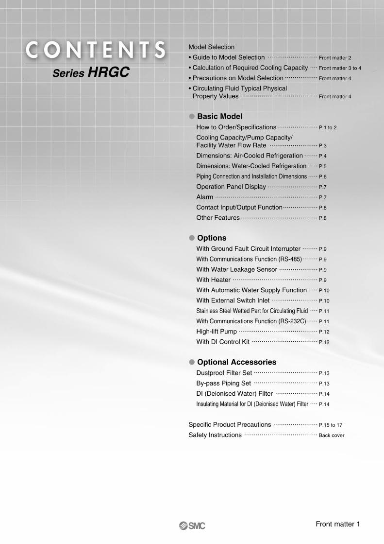
Model Selection
• Guide to Model Selection
• Calculation of Required Cooling Capacity
• Precautions on Model Selection
• Circulating Fluid Typical Physical Property Values
Basic ModelHow to Order/Specifications
Cooling Capacity/Pump Capacity/Facility Water Flow Rate
Dimensions: Air-Cooled Refrigeration
Dimensions: Water-Cooled Refrigeration
Piping Connection and Installation Dimensions
Operation Panel Display
Alarm
Contact Input/Output Function
Other Features
OptionsWith Ground Fault Circuit Interrupter
With Communications Function (RS-485)
With Water Leakage Sensor
With Heater
With Automatic Water Supply Function
With External Switch Inlet
Stainless Steel Wetted Part for Circulating Fluid
With Communications Function (RS-232C)
High-lift Pump
With DI Control Kit
Optional AccessoriesDustproof Filter Set
By-pass Piping Set
DI (Deionised Water) Filter
Insulating Material for DI (Deionised Water) Filter
Specific Product Precautions
Safety Instructions
Front matter 2
Front matter 3 to 4
Front matter 4
Front matter 4
P.1 to 2
P.3
P.4
P.5
P.6
P.7
P.7
P.8
P.8
P.9
P.9
P.9
P.9
P.10
P.10
P.11
P.11
P.12
P.12
P.13
P.13
P.14
P.14
P.15 to 17
Back cover
Series HRGC
Front matter 1
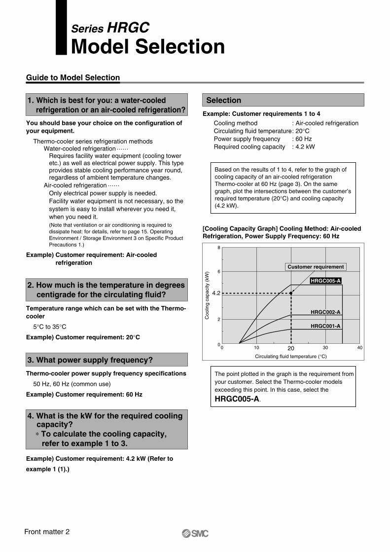
1. Which is best for you: a water-cooled refrigeration or an air-cooled refrigeration?
Guide to Model Selection
Series HRGCModel Selection
3. What power supply frequency?
Thermo-cooler power supply frequency specifications
50 Hz, 60 Hz (common use)
Example) Customer requirement: 60 Hz
You should base your choice on the configuration of your equipment.
Thermo-cooler series refrigeration methodsWater-cooled refrigeration
Requires facility water equipment (cooling tower etc.) as well as electrical power supply. This type provides stable cooling performance year round, regardless of ambient temperature changes.
Air-cooled refrigerationOnly electrical power supply is needed.Facility water equipment is not necessary, so the system is easy to install wherever you need it, when you need it.(Note that ventilation or air conditioning is required to dissipate heat: for details, refer to page 15. Operating Environment / Storage Environment 3 on Specific Product Precautions 1.)
Example) Customer requirement: Air-cooled refrigeration
Temperature range which can be set with the Thermo-cooler
5°C to 35°C
Example) Customer requirement: 20°C
Selection
Example: Customer requirements 1 to 4
Cooling method : Air-cooled refrigerationCirculating fluid temperature: 20°CPower supply frequency : 60 HzRequired cooling capacity : 4.2 kW
The point plotted in the graph is the requirement from your customer. Select the Thermo-cooler models exceeding this point. In this case, select the
HRGC005-A.
Based on the results of 1 to 4, refer to the graph of cooling capacity of an air-cooled refrigeration Thermo-cooler at 60 Hz (page 3). On the same graph, plot the intersections between the customer’s required temperature (20°C) and cooling capacity (4.2 kW).
[Cooling Capacity Graph] Cooling Method: Air-cooled Refrigeration, Power Supply Frequency: 60 Hz
0
2
6
8
4.2
0 10 30 4020Circulating fluid temperature (°C)
Coo
ling
capa
city
(kW
)
HRGC002-A
HRGC001-A
Customer requirement
HRGC005-A2. How much is the temperature in degrees
centigrade for the circulating fluid?
Example) Customer requirement: 4.2 kW (Refer to
example 1 (1).)
4. What is the kW for the required cooling capacity?
∗ To calculate the cooling capacity, refer to example 1 to 3.
Q: Heat generation amount
Customer’sequipment
I: Current
Power consumption
V: Power supply voltage
P
The heat generation amount can be determined based on the power consumption or output of the heat generating area — i.e. the area requiring cooling — within your facility.
Obtaining the temperature difference between inlet and outlet by circulating the circulating fluid inside the customer’s equipment.
(1) Derive the amount of heat generated from the power consumption.
Power consumption P: 3.5 [kW]
Q = P = 3.5 [kW]
Cooling capacity = Considering a safety factor of 20%,
3.5 [kW] x 1.2 = 4.2 [kW]
(2) Derive the amount of heat generated from the power supply output.
Power supply output VI: 4.1 [kVA]
Q = P = V x I x Power factor
In this example, using a power factor of 0.85:
= 4.1 [kVA] x 0.85 = 3.5 [kW]
Cooling capacity = Considering a safety factor of 20%,
3.5 [kW] x 1.2 = 4.2 [kW]
(3) Derive the amount of heat generated from the output.
Output (shaft power, etc.) W: 2.2 [kW]
Q = P =
In this example, use an efficiency of 0.7:
= = 3.14 [kW]
Cooling capacity = Considering a safety factor of 20%,
3.14 [kW] x 1.2 ≈ 3.8 [kW]
∗ The above examples calculate the heat generation amount based on the power consumption. The actual heat generation amount may differ due to the structure of customer facilities.Please be sure to check it carefully.
Calculation of Required Cooling Capacity
Thermo-cooler
Customer’sequipment
T1: Outlettemperature
T2: Returntemperature
qv: Circulating fluid flow rate
T=T2 – T1
Q: Heat generation amount
Example of the conventional measurement units (Reference)
Cooling capacity = Considering a safety factor of 20%,
3.5 [kW] x 1.2 = 4.2 [kW]
Example 1: When the heat generation amount in the customer's equipment is known.
Example 2: When the heat generation amount in the customer's equipment is not known.
WEfficiency
2.20.7
Amount of heat generated by equipment QCirculating fluidCirculating fluid flow rate (weight) qm
Circulating fluid density ρCirculating fluid flow rate (volume) qv
Circulating fluid specific heat capacity CCirculating fluid outlet temperature T1
Circulating fluid return temperature T2
Circulating fluid temperature difference TConversion factor: minutes to seconds (SI units)
: Unknown [kW] ([kJ/s]): Clear water∗: (= ρ x qv ÷ 60) [kg/s]: 1 [kg/dm3]: 25 [dm3/min]: 4.2 [kJ/(kg K)]: 293 [K] (20 [°C]): 295 [K] (22 [°C]): 2.0 [K] (= T2 – T1): 60 [s/min]
Q = qm x C x (T2 – T1)ρ x qv x C x T
60=
1 x 25 x 4.2 x 2.060
=
= 3.50 [kJ/s] ≈ 3.5 [kW]
Cooling capacity = Considering a safety factor of 20%,
3.5 [kW] x 1.2 = 4.2 [kW]
Amount of heat generated by equipment QCirculating fluidCirculating fluid flow rate (weight) qm
Circulating fluid weight: volume ratio γCirculating fluid flow rate (volume) qv
Circulating fluid specific heat capacity CCirculating fluid outlet temperature T1
Circulating fluid return temperature T2
Circulating fluid temperature difference TConversion factor: hours to minutesConversion factor: kcal/h to kW
: Unknown [kcal/h] → [kW]: Clear water∗: (= ρ x qv x 60) [kgf/h]: 1 [kgf/l]: 25 [l/min]: 1.0 [kcal/(kgf °C)]: 20 [°C]: 22 [°C]: 2.0 [°C] (= T2 – T1): 60 [min/h]: 860 [(kcal/h)/kW]
Q = qm x C x (T2 – T1)
860
3000 [kcal/h]860
≈ 3.5 [kW]
=
1 x 25 x 60 x 1.0 x 2.0860
=
γ x qv x 60 x C x T860
=
∗ Refer to front matter 4 for the typical physical property values of clear water or other circulating fluids.
Model Selection
Front matter 2

1. Which is best for you: a water-cooled refrigeration or an air-cooled refrigeration?
Guide to Model Selection
Series HRGCModel Selection
3. What power supply frequency?
Thermo-cooler power supply frequency specifications
50 Hz, 60 Hz (common use)
Example) Customer requirement: 60 Hz
You should base your choice on the configuration of your equipment.
Thermo-cooler series refrigeration methodsWater-cooled refrigeration
Requires facility water equipment (cooling tower etc.) as well as electrical power supply. This type provides stable cooling performance year round, regardless of ambient temperature changes.
Air-cooled refrigerationOnly electrical power supply is needed.Facility water equipment is not necessary, so the system is easy to install wherever you need it, when you need it.(Note that ventilation or air conditioning is required to dissipate heat: for details, refer to page 15. Operating Environment / Storage Environment 3 on Specific Product Precautions 1.)
Example) Customer requirement: Air-cooled refrigeration
Temperature range which can be set with the Thermo-cooler
5°C to 35°C
Example) Customer requirement: 20°C
Selection
Example: Customer requirements 1 to 4
Cooling method : Air-cooled refrigerationCirculating fluid temperature: 20°CPower supply frequency : 60 HzRequired cooling capacity : 4.2 kW
The point plotted in the graph is the requirement from your customer. Select the Thermo-cooler models exceeding this point. In this case, select the
HRGC005-A.
Based on the results of 1 to 4, refer to the graph of cooling capacity of an air-cooled refrigeration Thermo-cooler at 60 Hz (page 3). On the same graph, plot the intersections between the customer’s required temperature (20°C) and cooling capacity (4.2 kW).
[Cooling Capacity Graph] Cooling Method: Air-cooled Refrigeration, Power Supply Frequency: 60 Hz
0
2
6
8
4.2
0 10 30 4020Circulating fluid temperature (°C)
Coo
ling
capa
city
(kW
)
HRGC002-A
HRGC001-A
Customer requirement
HRGC005-A2. How much is the temperature in degrees
centigrade for the circulating fluid?
Example) Customer requirement: 4.2 kW (Refer to
example 1 (1).)
4. What is the kW for the required cooling capacity?
∗ To calculate the cooling capacity, refer to example 1 to 3.
Q: Heat generation amount
Customer’sequipment
I: Current
Power consumption
V: Power supply voltage
P
The heat generation amount can be determined based on the power consumption or output of the heat generating area — i.e. the area requiring cooling — within your facility.
Obtaining the temperature difference between inlet and outlet by circulating the circulating fluid inside the customer’s equipment.
(1) Derive the amount of heat generated from the power consumption.
Power consumption P: 3.5 [kW]
Q = P = 3.5 [kW]
Cooling capacity = Considering a safety factor of 20%,
3.5 [kW] x 1.2 = 4.2 [kW]
(2) Derive the amount of heat generated from the power supply output.
Power supply output VI: 4.1 [kVA]
Q = P = V x I x Power factor
In this example, using a power factor of 0.85:
= 4.1 [kVA] x 0.85 = 3.5 [kW]
Cooling capacity = Considering a safety factor of 20%,
3.5 [kW] x 1.2 = 4.2 [kW]
(3) Derive the amount of heat generated from the output.
Output (shaft power, etc.) W: 2.2 [kW]
Q = P =
In this example, use an efficiency of 0.7:
= = 3.14 [kW]
Cooling capacity = Considering a safety factor of 20%,
3.14 [kW] x 1.2 ≈ 3.8 [kW]
∗ The above examples calculate the heat generation amount based on the power consumption. The actual heat generation amount may differ due to the structure of customer facilities.Please be sure to check it carefully.
Calculation of Required Cooling Capacity
Thermo-cooler
Customer’sequipment
T1: Outlettemperature
T2: Returntemperature
qv: Circulating fluid flow rate
T=T2 – T1
Q: Heat generation amount
Example of the conventional measurement units (Reference)
Cooling capacity = Considering a safety factor of 20%,
3.5 [kW] x 1.2 = 4.2 [kW]
Example 1: When the heat generation amount in the customer's equipment is known.
Example 2: When the heat generation amount in the customer's equipment is not known.
WEfficiency
2.20.7
Amount of heat generated by equipment QCirculating fluidCirculating fluid flow rate (weight) qm
Circulating fluid density ρCirculating fluid flow rate (volume) qv
Circulating fluid specific heat capacity CCirculating fluid outlet temperature T1
Circulating fluid return temperature T2
Circulating fluid temperature difference TConversion factor: minutes to seconds (SI units)
: Unknown [kW] ([kJ/s]): Clear water∗: (= ρ x qv ÷ 60) [kg/s]: 1 [kg/dm3]: 25 [dm3/min]: 4.2 [kJ/(kg K)]: 293 [K] (20 [°C]): 295 [K] (22 [°C]): 2.0 [K] (= T2 – T1): 60 [s/min]
Q = qm x C x (T2 – T1)ρ x qv x C x T
60=
1 x 25 x 4.2 x 2.060
=
= 3.50 [kJ/s] ≈ 3.5 [kW]
Cooling capacity = Considering a safety factor of 20%,
3.5 [kW] x 1.2 = 4.2 [kW]
Amount of heat generated by equipment QCirculating fluidCirculating fluid flow rate (weight) qm
Circulating fluid weight: volume ratio γCirculating fluid flow rate (volume) qv
Circulating fluid specific heat capacity CCirculating fluid outlet temperature T1
Circulating fluid return temperature T2
Circulating fluid temperature difference TConversion factor: hours to minutesConversion factor: kcal/h to kW
: Unknown [kcal/h] → [kW]: Clear water∗: (= ρ x qv x 60) [kgf/h]: 1 [kgf/l]: 25 [l/min]: 1.0 [kcal/(kgf °C)]: 20 [°C]: 22 [°C]: 2.0 [°C] (= T2 – T1): 60 [min/h]: 860 [(kcal/h)/kW]
Q = qm x C x (T2 – T1)
860
3000 [kcal/h]860
≈ 3.5 [kW]
=
1 x 25 x 60 x 1.0 x 2.0860
=
γ x qv x 60 x C x T860
=
∗ Refer to front matter 4 for the typical physical property values of clear water or other circulating fluids.
Model Selection
Front matter 3
Thermo-cooler
Water bath
V
After 15 min, cool down from 32°C to 20°C.
20°C
Q x t: Heat volume [kJ]
Calculation of Required Cooling Capacity Precautions on Model Selection
Circulating Fluid Typical Physical Property Values
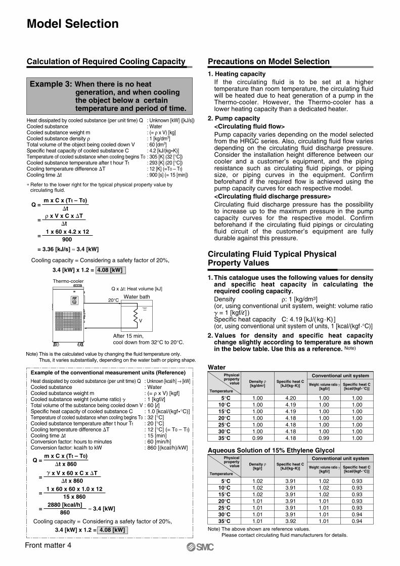
WaterPhysicalproperty
value
Conventional unit system
Temperature
5°C10°C15°C20°C25°C30°C35°C
Density ρ[kg/dm3]
Specific heat C[kJ/(kg K)]
4.204.194.194.184.184.184.18
1.001.001.001.001.001.001.00
1.001.001.001.001.001.000.99
1.001.001.001.001.001.000.99
Aqueous Solution of 15% Ethylene Glycol
Note) The above shown are reference values.Please contact circulating fluid manufacturers for details.
5°C10°C15°C20°C25°C30°C35°C
3.913.913.913.913.913.913.92
0.930.930.930.930.930.940.94
1.021.021.021.011.011.011.01
1.021.021.021.011.011.011.01
Example 3: When there is no heat generation, and when cooling the object below a certain temperature and period of time.
∗ Refer to the lower right for the typical physical property value by circulating fluid.
Cooling capacity = Considering a safety factor of 20%,
3.4 [kW] x 1.2 = 4.08 [kW]
Q = m x C x (Tt – T0)
t
= ρ x V x C x T
t
= 1 x 60 x 4.2 x 12
900
= 3.36 [kJ/s] ≈ 3.4 [kW]
Note) This is the calculated value by changing the fluid temperature only. Thus, it varies substantially, depending on the water bath or piping shape.
Heat dissipated by cooled substance (per unit time) QCooled substanceCooled substance weight mCooled substance density ρTotal volume of the object being cooled down VSpecific heat capacity of cooled substance CTemperature of cooled substance when cooling begins T0
Cooled substance temperature after t hour Tt
Cooling temperature difference TCooling time t
: Unknown [kW] ([kJ/s]): Water: (= ρ x V) [kg]: 1 [kg/dm3]: 60 [dm3]: 4.2 [kJ/(kgK)]: 305 [K] (32 [°C]): 293 [K] (20 [°C]): 12 [K] (=T0 – Tt): 900 [s] (= 15 [min])
Heat dissipated by cooled substance (per unit time) QCooled substanceCooled substance weight mCooled substance weight (volume ratio) Total volume of the substance being cooled down VSpecific heat capacity of cooled substance CTemperature of cooled substance when cooling begins T0
Cooled substance temperature after t hour Tt
Cooling temperature difference TCooling time tConversion factor: hours to minutesConversion factor: kcal/h to kW
: Unknown [kcal/h] → [kW]: Water: (= ρ x V) [kgf]: 1 [kgf/l]: 60 [l]: 1.0 [kcal/(kgf °C)]: 32 [°C]: 20 [°C]: 12 [°C] (= T0 – Tt): 15 [min]: 60 [min/h]: 860 [(kcal/h)/kW]
Example of the conventional measurement units (Reference)
Q =m x C x (Tt – T0)
t x 860
= x V x 60 x C x T
t x 860
=1 x 60 x 60 x 1.0 x 12
15 x 860
= ≈ 3.4 [kW]2880 [kcal/h]
860
Cooling capacity = Considering a safety factor of 20%,
3.4 [kW] x 1.2 = 4.08 [kW]
1. Heating capacity If the circulating fluid is to be set at a higher temperature than room temperature, the circulating fluid will be heated due to heat generation of a pump in the Thermo-cooler. However, the Thermo-cooler has a lower heating capacity than a dedicated heater.
2. Pump capacity <Circulating fluid flow> Pump capacity varies depending on the model selected from the HRGC series. Also, circulating fluid flow varies depending on the circulating fluid discharge pressure. Consider the installation height difference between our cooler and a customer’s equipment, and the piping resistance such as circulating fluid pipings, or piping size, or piping curves in the equipment. Confirm beforehand if the required flow is achieved using the pump capacity curves for each respective model. <Circulating fluid discharge pressure>Circulating fluid discharge pressure has the possibility to increase up to the maximum pressure in the pump capacity curves for the respective model. Confirm beforehand if the circulating fluid pipings or circulating fluid circuit of the customer’s equipment are fully durable against this pressure.
1. This catalogue uses the following values for density and specific heat capacity in calculating the required cooling capacity.Density ρ: 1 [kg/dm3](or, using conventional unit system, weight: volume ratio = 1 [kgf/l ] ) Specific heat capacity C: 4.19 [kJ/(kg·K) ](or, using conventional unit system of units, 1 [kcal/(kgf ·°C)]
2. Values for density and specific heat capacity change slightly according to temperature as shown in the below table. Use this as a reference. Note)
Specific heat C[kcal/(kgf °C)]
Weight: volume ratio [kgf/l]
Physicalproperty
value
Conventional unit system
Temperature
Density ρ[kg/l]
Specific heat C[kJ/(kg K)] Specific heat C
[kcal/(kgf °C)]Weight: volume ratio
[kgf/l]
Model Selection
Front matter 4
Thermo-cooler
Water bath
V
After 15 min, cool down from 32°C to 20°C.
20°C
Q x t: Heat volume [kJ]
Calculation of Required Cooling Capacity Precautions on Model Selection
Circulating Fluid Typical Physical Property Values
WaterPhysicalproperty
value
Conventional unit system
Temperature
5°C10°C15°C20°C25°C30°C35°C
Density ρ[kg/dm3]
Specific heat C[kJ/(kg K)]
4.204.194.194.184.184.184.18
1.001.001.001.001.001.001.00
1.001.001.001.001.001.000.99
1.001.001.001.001.001.000.99
Aqueous Solution of 15% Ethylene Glycol
Note) The above shown are reference values.Please contact circulating fluid manufacturers for details.
5°C10°C15°C20°C25°C30°C35°C
3.913.913.913.913.913.913.92
0.930.930.930.930.930.940.94
1.021.021.021.011.011.011.01
1.021.021.021.011.011.011.01
Example 3: When there is no heat generation, and when cooling the object below a certain temperature and period of time.
∗ Refer to the lower right for the typical physical property value by circulating fluid.
Cooling capacity = Considering a safety factor of 20%,
3.4 [kW] x 1.2 = 4.08 [kW]
Q = m x C x (Tt – T0)
t
= ρ x V x C x T
t
= 1 x 60 x 4.2 x 12
900
= 3.36 [kJ/s] ≈ 3.4 [kW]
Note) This is the calculated value by changing the fluid temperature only. Thus, it varies substantially, depending on the water bath or piping shape.
Heat dissipated by cooled substance (per unit time) QCooled substanceCooled substance weight mCooled substance density ρTotal volume of the object being cooled down VSpecific heat capacity of cooled substance CTemperature of cooled substance when cooling begins T0
Cooled substance temperature after t hour Tt
Cooling temperature difference TCooling time t
: Unknown [kW] ([kJ/s]): Water: (= ρ x V) [kg]: 1 [kg/dm3]: 60 [dm3]: 4.2 [kJ/(kgK)]: 305 [K] (32 [°C]): 293 [K] (20 [°C]): 12 [K] (=T0 – Tt): 900 [s] (= 15 [min])
Heat dissipated by cooled substance (per unit time) QCooled substanceCooled substance weight mCooled substance weight (volume ratio) Total volume of the substance being cooled down VSpecific heat capacity of cooled substance CTemperature of cooled substance when cooling begins T0
Cooled substance temperature after t hour Tt
Cooling temperature difference TCooling time tConversion factor: hours to minutesConversion factor: kcal/h to kW
: Unknown [kcal/h] → [kW]: Water: (= ρ x V) [kgf]: 1 [kgf/l]: 60 [l]: 1.0 [kcal/(kgf °C)]: 32 [°C]: 20 [°C]: 12 [°C] (= T0 – Tt): 15 [min]: 60 [min/h]: 860 [(kcal/h)/kW]
Example of the conventional measurement units (Reference)
Q =m x C x (Tt – T0)
t x 860
= x V x 60 x C x T
t x 860
=1 x 60 x 60 x 1.0 x 12
15 x 860
= ≈ 3.4 [kW]2880 [kcal/h]
860
Cooling capacity = Considering a safety factor of 20%,
3.4 [kW] x 1.2 = 4.08 [kW]
1. Heating capacity If the circulating fluid is to be set at a higher temperature than room temperature, the circulating fluid will be heated due to heat generation of a pump in the Thermo-cooler. However, the Thermo-cooler has a lower heating capacity than a dedicated heater.
2. Pump capacity <Circulating fluid flow> Pump capacity varies depending on the model selected from the HRGC series. Also, circulating fluid flow varies depending on the circulating fluid discharge pressure. Consider the installation height difference between our cooler and a customer’s equipment, and the piping resistance such as circulating fluid pipings, or piping size, or piping curves in the equipment. Confirm beforehand if the required flow is achieved using the pump capacity curves for each respective model. <Circulating fluid discharge pressure>Circulating fluid discharge pressure has the possibility to increase up to the maximum pressure in the pump capacity curves for the respective model. Confirm beforehand if the circulating fluid pipings or circulating fluid circuit of the customer’s equipment are fully durable against this pressure.
1. This catalogue uses the following values for density and specific heat capacity in calculating the required cooling capacity.Density ρ: 1 [kg/dm3](or, using conventional unit system, weight: volume ratio = 1 [kgf/l ] ) Specific heat capacity C: 4.19 [kJ/(kg·K) ](or, using conventional unit system of units, 1 [kcal/(kgf ·°C)]
2. Values for density and specific heat capacity change slightly according to temperature as shown in the below table. Use this as a reference. Note)
Specific heat C[kcal/(kgf °C)]
Weight: volume ratio [kgf/l]
Physicalproperty
value
Conventional unit system
Temperature
Density ρ[kg/l]
Specific heat C[kJ/(kg K)] Specific heat C
[kcal/(kgf °C)]Weight: volume ratio
[kgf/l]
Model Selection
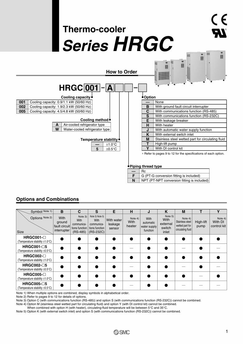
How to Order
Thermo-cooler
Series HRGC
001 AHRGCCooling capacity
001002005
Cooling capacity: 0.9/1.1 kW (50/60 Hz)Cooling capacity: 1.9/2.3 kW (50/60 Hz)Cooling capacity: 4.5/4.8 kW (50/60 Hz)
Cooling methodAW
Air-cooled refrigerator typeWater-cooled refrigerator type
Temperature stability—5
±1.0°C±0.5°C
Option
∗ Refer to pages 9 to 12 for the specifications of each option.
—BCSEHJKMTY
NoneWith ground fault circuit interrupter With communications function (RS-485)With communications function (RS-232C)With leakage breakerWith heaterWith automatic water supply functionWith external switch inletStainless steel wetted part for circulating fluidHigh-lift pumpWith DI control kit
Piping thread type—FN
Options and Combinations
Note 1) When multiple options are combined, display symbols in alphabetical order.Note 2) Refer to pages 9 to 12 for details of options.Note 3) Option C (with communications function (RS-485)) and option S (with communications function (RS-232C)) cannot be combined.Note 4) Option M (stainless steel wetted part for circulating fluid) and option Y (with DI control kit) cannot be combined.
When combined with option H (with heater), circulating-fluid temperature will be between 5°C and 35°C.Note 5) Option K (with external switch inlet) and option S (with communications function (RS-232C)) cannot be combined.
Symbol Note 1)
Size
HRGC001-(Temperature stability ±1.0°C)
HRGC001-5(Temperature stability ±0.5°C)
HRGC002-(Temperature stability ±1.0°C)
HRGC002-5(Temperature stability ±0.5°C)
HRGC005-(Temperature stability ±1.0°C)
HRGC005-5(Temperature stability ±0.5°C)
Options Note 2) Withground
fault circuitinterrupter
Withcommunica-tions function(RS-485)
Withcommunica-tions function(RS-232C)
With waterleakagesensor
Withheater
Withautomatic
water supplyfunction
Withexternalswitchinlet
Stainless steelwetted part forcirculating fluid
High-liftpump
With DIcontrol kit
B C S E H J K M T YNote 3) Note 5)Note 3) Note 5)
Note 4) Note 4) Note 4)
RcG (PT-G conversion fitting is included)NPT (PT-NPT conversion fitting is included)
1

HRGC001, 002, 005
Specifications (Refer to the product specifications for details.)
Note 1) It should have no condensation.During seasons or in locations where the ambient temperature is likely to fall below the freezing point, please consult SMC separately.
Note 2) If clear water is to be used, please use water that conforms to Clear Water Quality Standard of the Japan Refrigeration and Air Conditioning Industrial Association (JRA GL-02-1994 cooling water system - circulating type - make-up water).Deionised water can be used only for supply water. Supply water with electrical conductivity of 1 µS/cm or more. (Electrical resistivity: 1 MΩ·cm or less) An optional DI control kit (symbol Y) is available to maintain electrical resistance. Refer to page 12 for details. If ethylene glycol aqueous solution is used, concentration must be 15%.
Note 3) q Ambient temperature: 32°C, Facility water temperature: 25°C (water-cooled refrigeration), w Circulating fluid temperature: 20°C, e Circulating fluid flow rate: Values at circulating fluid rated flow rate.
Note 4) Thermo-cooler specifications do not have heating capability.(When heating capability is required, use a product with an optional heater (symbol H). Refer to page 9 for details.)
Note 5) Temperature at the Thermo-cooler outlet when the circulating fluid has a rated flow, and the facility water with the circulating fluid supply and return are directly connected. The installation environment, power supply and facility water should be stable within the specified range.
Note 6) Capacity of the Thermo-cooler outlet when the circulating fluid temperature is at 20°C.Note 7) Required flow for cooling capacity or maintaining the temperature stability.
When used below the rated flow, open the standard manual by-pass valve and maintain a circulating fluid flow rate equivalent to the rated flow.Also use the by-pass piping set sold separately.
Note 8) Required flow when a load is applied as shown in the cooling capacity when the facility water temperature is at 25°C. Note 9) Purchase a ground fault circuit interrupter with current sensitivity of 30 mA separately. (Optional circuit breaker (symbol B) is also available. Refer
to page 9.)Note 10) Weight in the dry state, without circulating fluids.Note 11) In case of refrigerator ON/OFF control. For other conditions, refer to Note 3).
Model HRGC001 HRGC002 HRGC005Cooling method
Refrigerant
Control method
Ambient temperature/humidity Note 1)
R407C (HFC)
Refrigerator ON/OFF control or Proportional valve PID control
Temperature: 5 to 40°C, Humidity: 30 to 70%RH
Clear water, Deionised water, Aqueous solution of 15% ethylene glycol
For externally sealed circuit
5 to 35
Air-cooled refrigeration
—
Water-cooled refrigeration
±1.0 (Refrigerator ON/OFF control), ±0.5 (Proportional valve PID control)
Rc1/2
15 15 30
0.13/0.18 (at 10 l/min)
10/10
Approx. 10
0.21/0.32 (at 23 l/28 l/min)
23/28
Approx. 20
Relay contact input (operates when the switch is closed, stops when the switch is opened)
Relay contact output (switch closed when operating, switch open when stopped, switch open when shut down)
Relay contact output (switch closed when alarm is turned off, switch open when alarm is turned on, switch closed when shut down)
Refer to page 7.
Stainless steel, PVC, Copper brazing (heat exchanger), Bronze, Brass
Single-phase 200 to 230 VAC 50/60 Hz Allowable voltage fluctuation ±10%
Stainless steel, PPE, PVC, Copper brazing (Heat exchanger), Bronze, Brass
— — — — —
—
—
—
—
5 to 32
0.3 to 0.5
10/12
Rc1/2
—
—
—
—
5 to 32
0.3 to 0.5
10/12
Rc1/2
—
—
—
—
5 to 32
0.3 to 0.5
27/28
Rc1/2
8.1
0.76/0.82
7.8
0.68/0.73
8.6
1.13/1.20
8.0
0.89/0.98
17.2
2.07/2.23
14.1
1.76/1.83
75 75 75 75 110 110
Air-cooled refrigeration Water-cooled refrigeration Air-cooled refrigeration Water-cooled refrigeration
Accessories (Enclosed)Content
Eye bolts M12 (4 pcs.)
Y-type strainer (1 pc.)
Applicable model
HRGC005
Water-cooled type
• Eye bolts are included in HRGC005. (Not assembled)• A Y-type strainer is included in the water cooled type. (Not assembled)
Weight Note 10)
Cir
cula
tin
g f
luid
sys
tem
Fac
ility
wat
er s
yste
mE
lect
rica
l sys
tem
Circulating fluid Note 2)
Circulating method
Temperature range setting Note 1)
Cooling capacity Note 3) (50/60 Hz)
Heating capacity Note 4)
Temperature stability Note 5)
Pump capacity Note 6)(50/60 Hz)
Rated flow Note 7) (50/60 Hz)
Tank capacity
Port size
Wetted parts material
Temperature range
Pressure range
Required flow rate Note 8) (50/60 Hz)
Port size
Wetted parts material
Power supply
Applicable ground fault circuit interrupter capacity Note 9)
Maximum operating current
Rated power consumption Note 11) (50/60 Hz)
Remote operation signal input
Operation signal output
Alarm stop signal output
Alarm
°C
kW
kW
°CMPa
l /min
l
°CMPa
l/min
A
A
kW
kg
0.9/1.1 (at 20°C)
0.9/1.1 (at 20°C)
1.9/2.3 (at 20°C)
1.9/2.3 (at 20°C)
4.5/4.8 (at 20°C)
4.5/4.8 (at 20°C)
Series HRGC
Coo
ling
capa
city
(kW
)
Circulating fluid temperature (°C)
4
3
2
1
0
5
6
0 10 20 30 40
60 [Hz]
50 [Hz]
Coo
ling
capa
city
(kW
)
Circulating fluid temperature (°C)
1
0 10 20 30 40
60 [Hz]
50 [Hz]
0.5
0
1.5
Circulating fluid flow (l/min)
0 10 20 30
0.3
0.2
0.1
0.0
30
20
10
0
Outlet [60 Hz] Outlet [50 Hz]
Return port
Coo
ling
capa
city
(kW
)
Circulating fluid temperature (°C)
2
1
3
00 10 20 30 40
60 [Hz]
50 [Hz]
Circulating fluid flow (l/min)
0 10 20 4030
50
40
30
20
10
0
Outlet [60 Hz]
Outlet [50 Hz]
0 10 20 30 40
30
20
10
0
Facility water inlet temperature (°C)
Fac
ility
wat
er fl
ow r
ate
(l/m
in) HRGC005-W
HRGC002-W
HRGC001-W
Pressure[MPa]
Lifting height[m]
0.5
0.4
0.3
0.2
0.1
0.0Pressure[MPa]
Lifting height[m]
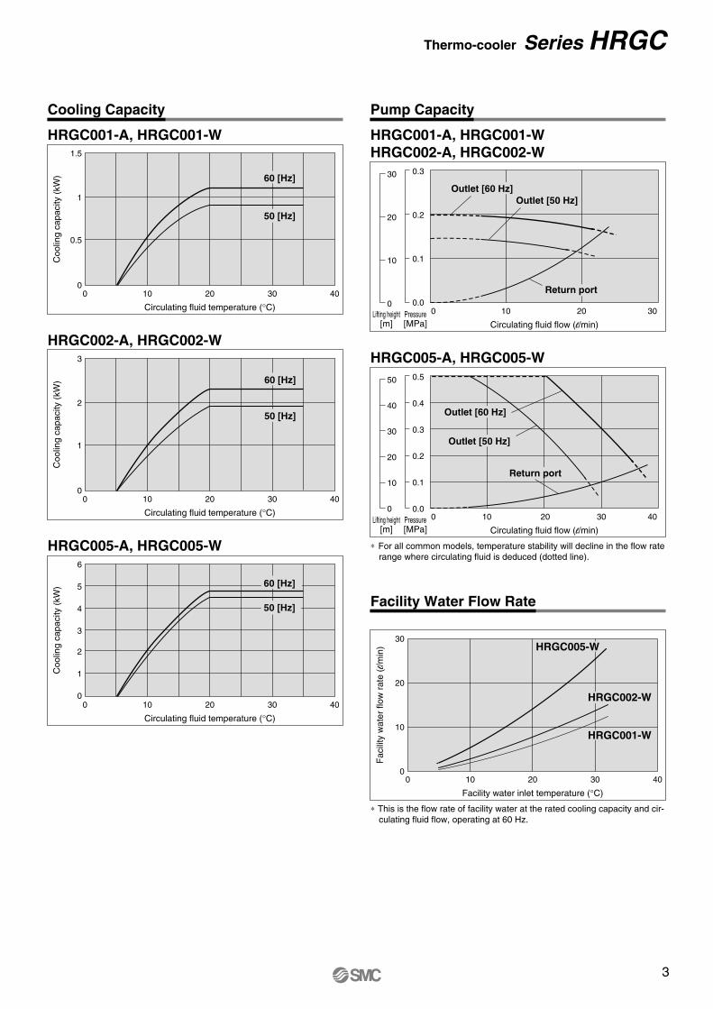
Cooling Capacity
HRGC001-A, HRGC001-W
Facility Water Flow Rate
∗ This is the flow rate of facility water at the rated cooling capacity and cir-culating fluid flow, operating at 60 Hz.
HRGC002-A, HRGC002-W
HRGC005-A, HRGC005-W
Pump Capacity
HRGC001-A, HRGC001-WHRGC002-A, HRGC002-W
HRGC005-A, HRGC005-W
∗ For all common models, temperature stability will decline in the flow rate range where circulating fluid is deduced (dotted line).
Return port
Thermo-cooler Series HRGC
2
HRGC001, 002, 005
Specifications (Refer to the product specifications for details.)
Note 1) It should have no condensation.During seasons or in locations where the ambient temperature is likely to fall below the freezing point, please consult SMC separately.
Note 2) If clear water is to be used, please use water that conforms to Clear Water Quality Standard of the Japan Refrigeration and Air Conditioning Industrial Association (JRA GL-02-1994 cooling water system - circulating type - make-up water).Deionised water can be used only for supply water. Supply water with electrical conductivity of 1 µS/cm or more. (Electrical resistivity: 1 MΩ·cm or less) An optional DI control kit (symbol Y) is available to maintain electrical resistance. Refer to page 12 for details. If ethylene glycol aqueous solution is used, concentration must be 15%.
Note 3) q Ambient temperature: 32°C, Facility water temperature: 25°C (water-cooled refrigeration), w Circulating fluid temperature: 20°C, e Circulating fluid flow rate: Values at circulating fluid rated flow rate.
Note 4) Thermo-cooler specifications do not have heating capability.(When heating capability is required, use a product with an optional heater (symbol H). Refer to page 9 for details.)
Note 5) Temperature at the Thermo-cooler outlet when the circulating fluid has a rated flow, and the facility water with the circulating fluid supply and return are directly connected. The installation environment, power supply and facility water should be stable within the specified range.
Note 6) Capacity of the Thermo-cooler outlet when the circulating fluid temperature is at 20°C.Note 7) Required flow for cooling capacity or maintaining the temperature stability.
When used below the rated flow, open the standard manual by-pass valve and maintain a circulating fluid flow rate equivalent to the rated flow.Also use the by-pass piping set sold separately.
Note 8) Required flow when a load is applied as shown in the cooling capacity when the facility water temperature is at 25°C. Note 9) Purchase a ground fault circuit interrupter with current sensitivity of 30 mA separately. (Optional circuit breaker (symbol B) is also available. Refer
to page 9.)Note 10) Weight in the dry state, without circulating fluids.Note 11) In case of refrigerator ON/OFF control. For other conditions, refer to Note 3).
Model HRGC001 HRGC002 HRGC005Cooling method
Refrigerant
Control method
Ambient temperature/humidity Note 1)
R407C (HFC)
Refrigerator ON/OFF control or Proportional valve PID control
Temperature: 5 to 40°C, Humidity: 30 to 70%RH
Clear water, Deionised water, Aqueous solution of 15% ethylene glycol
For externally sealed circuit
5 to 35
Air-cooled refrigeration
—
Water-cooled refrigeration
±1.0 (Refrigerator ON/OFF control), ±0.5 (Proportional valve PID control)
Rc1/2
15 15 30
0.13/0.18 (at 10 l/min)
10/10
Approx. 10
0.21/0.32 (at 23 l/28 l/min)
23/28
Approx. 20
Relay contact input (operates when the switch is closed, stops when the switch is opened)
Relay contact output (switch closed when operating, switch open when stopped, switch open when shut down)
Relay contact output (switch closed when alarm is turned off, switch open when alarm is turned on, switch closed when shut down)
Refer to page 7.
Stainless steel, PVC, Copper brazing (heat exchanger), Bronze, Brass
Single-phase 200 to 230 VAC 50/60 Hz Allowable voltage fluctuation ±10%
Stainless steel, PPE, PVC, Copper brazing (Heat exchanger), Bronze, Brass
— — — — —
—
—
—
—
5 to 32
0.3 to 0.5
10/12
Rc1/2
—
—
—
—
5 to 32
0.3 to 0.5
10/12
Rc1/2
—
—
—
—
5 to 32
0.3 to 0.5
27/28
Rc1/2
8.1
0.76/0.82
7.8
0.68/0.73
8.6
1.13/1.20
8.0
0.89/0.98
17.2
2.07/2.23
14.1
1.76/1.83
75 75 75 75 110 110
Air-cooled refrigeration Water-cooled refrigeration Air-cooled refrigeration Water-cooled refrigeration
Accessories (Enclosed)Content
Eye bolts M12 (4 pcs.)
Y-type strainer (1 pc.)
Applicable model
HRGC005
Water-cooled type
• Eye bolts are included in HRGC005. (Not assembled)• A Y-type strainer is included in the water cooled type. (Not assembled)
Weight Note 10)
Cir
cula
tin
g f
luid
sys
tem
Fac
ility
wat
er s
yste
mE
lect
rica
l sys
tem
Circulating fluid Note 2)
Circulating method
Temperature range setting Note 1)
Cooling capacity Note 3) (50/60 Hz)
Heating capacity Note 4)
Temperature stability Note 5)
Pump capacity Note 6)(50/60 Hz)
Rated flow Note 7) (50/60 Hz)
Tank capacity
Port size
Wetted parts material
Temperature range
Pressure range
Required flow rate Note 8) (50/60 Hz)
Port size
Wetted parts material
Power supply
Applicable ground fault circuit interrupter capacity Note 9)
Maximum operating current
Rated power consumption Note 11) (50/60 Hz)
Remote operation signal input
Operation signal output
Alarm stop signal output
Alarm
°C
kW
kW
°CMPa
l /min
l
°CMPa
l/min
A
A
kW
kg
0.9/1.1 (at 20°C)
0.9/1.1 (at 20°C)
1.9/2.3 (at 20°C)
1.9/2.3 (at 20°C)
4.5/4.8 (at 20°C)
4.5/4.8 (at 20°C)
Series HRGCC
oolin
g ca
paci
ty (
kW)
Circulating fluid temperature (°C)
4
3
2
1
0
5
6
0 10 20 30 40
60 [Hz]
50 [Hz]
Coo
ling
capa
city
(kW
)
Circulating fluid temperature (°C)
1
0 10 20 30 40
60 [Hz]
50 [Hz]
0.5
0
1.5
Circulating fluid flow (l/min)
0 10 20 30
0.3
0.2
0.1
0.0
30
20
10
0
Outlet [60 Hz] Outlet [50 Hz]
Return port
Coo
ling
capa
city
(kW
)
Circulating fluid temperature (°C)
2
1
3
00 10 20 30 40
60 [Hz]
50 [Hz]
Circulating fluid flow (l/min)
0 10 20 4030
50
40
30
20
10
0
Outlet [60 Hz]
Outlet [50 Hz]
0 10 20 30 40
30
20
10
0
Facility water inlet temperature (°C)
Fac
ility
wat
er fl
ow r
ate
(l/m
in) HRGC005-W
HRGC002-W
HRGC001-W
Pressure[MPa]
Lifting height[m]
0.5
0.4
0.3
0.2
0.1
0.0Pressure[MPa]
Lifting height[m]
Cooling Capacity
HRGC001-A, HRGC001-W
Facility Water Flow Rate
∗ This is the flow rate of facility water at the rated cooling capacity and cir-culating fluid flow, operating at 60 Hz.
HRGC002-A, HRGC002-W
HRGC005-A, HRGC005-W
Pump Capacity
HRGC001-A, HRGC001-WHRGC002-A, HRGC002-W
HRGC005-A, HRGC005-W
∗ For all common models, temperature stability will decline in the flow rate range where circulating fluid is deduced (dotted line).
Return port
Thermo-cooler Series HRGC
3
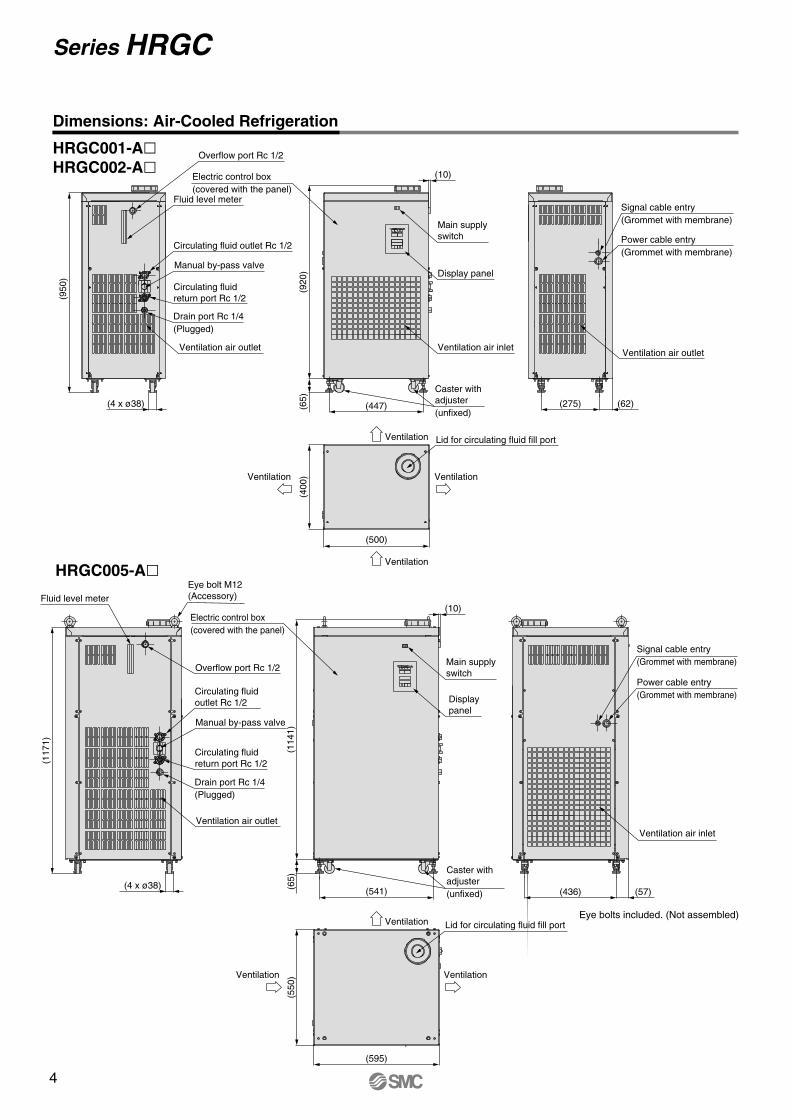
Dimensions: Air-Cooled Refrigeration
HRGC001-AHRGC002-A
HRGC005-A
Ventilation Lid for circulating fluid fill port
(595)
(550
) VentilationVentilation
(500)
(400
)
Ventilation
Ventilation
Ventilation
Lid for circulating fluid fill port
Ventilation
Overflow port Rc 1/2
Fluid level meter
Circulating fluid outlet Rc 1/2
Manual by-pass valve
Circulating fluid return port Rc 1/2
(4 x ø38)
(950
)
Ventilation air outlet
Drain port Rc 1/4(Plugged)
(10)
(447)
(920
)(6
5)
Ventilation air inlet
Display panel
Main supply switch
Caster with adjuster (unfixed)
Electric control box(covered with the panel)
(275) (62)
Power cable entry(Grommet with membrane)
Signal cable entry(Grommet with membrane)
Ventilation air outlet
(436) (57)
Power cable entry(Grommet with membrane)
Signal cable entry(Grommet with membrane)
Ventilation air inlet
Overflow port Rc 1/2
Fluid level meter
Circulating fluid outlet Rc 1/2
Manual by-pass valve
Circulating fluid return port Rc 1/2
Ventilation air outlet
Drain port Rc 1/4(Plugged)
(117
1)
(4 x ø38)
Eye bolt M12 (Accessory)
(10)
(114
1)(6
5)
(541)
Display panel
Main supply switch
Electric control box(covered with the panel)
Caster with adjuster (unfixed)
Eye bolts included. (Not assembled)
Series HRGC
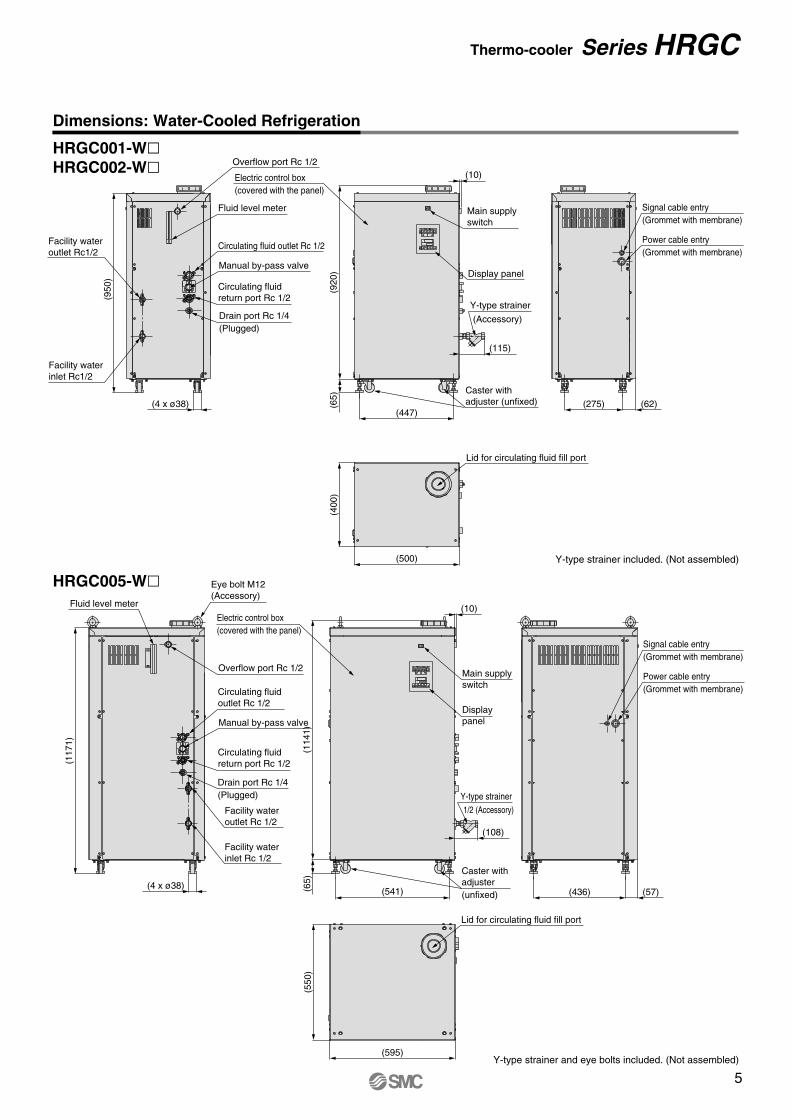
Dimensions: Water-Cooled Refrigeration
HRGC001-WHRGC002-W
HRGC005-W(500)
(400
)
Lid for circulating fluid fill port
(275) (62)
Power cable entry(Grommet with membrane)
Signal cable entry(Grommet with membrane)
(10)
(447)
(920
)(6
5)
Caster with adjuster (unfixed)
Y-type strainer included. (Not assembled)
Y-type strainer and eye bolts included. (Not assembled)
Electric control box(covered with the panel)
(595)
(550
)
Lid for circulating fluid fill port
(10)
(114
1)(6
5)
(541)
Display panel
Main supply switch
Circulating fluid outlet Rc 1/2
Manual by-pass valve
Circulating fluid return port Rc 1/2
Drain port Rc 1/4(Plugged)
(117
1)
(4 x ø38)
Facility water inlet Rc 1/2
Facility water outlet Rc 1/2
Eye bolt M12 (Accessory)
Fluid level meter
Overflow port Rc 1/2
(115)
(Accessory)
Y-type strainer
(108)
1/2 (Accessory)
Y-type strainer
Overflow port Rc 1/2
Fluid level meter
Circulating fluid outlet Rc 1/2
Manual by-pass valve
Circulating fluid return port Rc 1/2
(4 x ø38)
(950
)
Facility water inlet Rc1/2
Drain port Rc 1/4(Plugged)
Facility water outlet Rc1/2
(436) (57)
Power cable entry(Grommet with membrane)
Signal cable entry(Grommet with membrane)
Electric control box(covered with the panel)
Caster with adjuster (unfixed)
Display panel
Main supply switch
Thermo-cooler Series HRGC
4
Dimensions: Air-Cooled Refrigeration
HRGC001-AHRGC002-A
HRGC005-A
Ventilation Lid for circulating fluid fill port
(595)
(550
) VentilationVentilation
(500)
(400
)
Ventilation
Ventilation
Ventilation
Lid for circulating fluid fill port
Ventilation
Overflow port Rc 1/2
Fluid level meter
Circulating fluid outlet Rc 1/2
Manual by-pass valve
Circulating fluid return port Rc 1/2
(4 x ø38)
(950
)
Ventilation air outlet
Drain port Rc 1/4(Plugged)
(10)
(447)
(920
)(6
5)
Ventilation air inlet
Display panel
Main supply switch
Caster with adjuster (unfixed)
Electric control box(covered with the panel)
(275) (62)
Power cable entry(Grommet with membrane)
Signal cable entry(Grommet with membrane)
Ventilation air outlet
(436) (57)
Power cable entry(Grommet with membrane)
Signal cable entry(Grommet with membrane)
Ventilation air inlet
Overflow port Rc 1/2
Fluid level meter
Circulating fluid outlet Rc 1/2
Manual by-pass valve
Circulating fluid return port Rc 1/2
Ventilation air outlet
Drain port Rc 1/4(Plugged)
(117
1)
(4 x ø38)
Eye bolt M12 (Accessory)
(10)
(114
1)(6
5)
(541)
Display panel
Main supply switch
Electric control box(covered with the panel)
Caster with adjuster (unfixed)
Eye bolts included. (Not assembled)
Series HRGC
Dimensions: Water-Cooled Refrigeration
HRGC001-WHRGC002-W
HRGC005-W(500)
(400
)
Lid for circulating fluid fill port
(275) (62)
Power cable entry(Grommet with membrane)
Signal cable entry(Grommet with membrane)
(10)
(447)
(920
)(6
5)
Caster with adjuster (unfixed)
Y-type strainer included. (Not assembled)
Y-type strainer and eye bolts included. (Not assembled)
Electric control box(covered with the panel)
(595)
(550
)
Lid for circulating fluid fill port
(10)
(114
1)(6
5)
(541)
Display panel
Main supply switch
Circulating fluid outlet Rc 1/2
Manual by-pass valve
Circulating fluid return port Rc 1/2
Drain port Rc 1/4(Plugged)
(117
1)
(4 x ø38)
Facility water inlet Rc 1/2
Facility water outlet Rc 1/2
Eye bolt M12 (Accessory)
Fluid level meter
Overflow port Rc 1/2
(115)
(Accessory)
Y-type strainer
(108)
1/2 (Accessory)
Y-type strainer
Overflow port Rc 1/2
Fluid level meter
Circulating fluid outlet Rc 1/2
Manual by-pass valve
Circulating fluid return port Rc 1/2
(4 x ø38)
(950
)
Facility water inlet Rc1/2
Drain port Rc 1/4(Plugged)
Facility water outlet Rc1/2
(436) (57)
Power cable entry(Grommet with membrane)
Signal cable entry(Grommet with membrane)
Electric control box(covered with the panel)
Caster with adjuster (unfixed)
Display panel
Main supply switch
Thermo-cooler Series HRGC
5
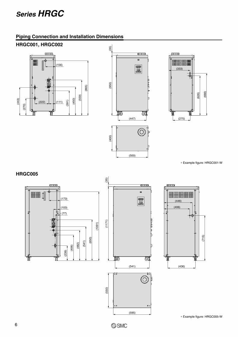
Piping Connection and Installation Dimensions
HRGC001, HRGC002
∗ Example figure: HRGC001-W
∗ Example figure: HRGC005-W
HRGC005
(156)
(111)(222)
(443
)
(270
)
(865
)
(559
)
(450
)
(391
)
(500)
(400
)(3
5)(9
50)
(447)
(333)
(666
)
(626
)
(275)
(173)
(103)
(77)
(109
1)
(650
)
(541
)
(482
)
(406
)
(239
)
(595)
(550
)(3
5)(1
171)
(541)
(446)
(406)
(715
)
(436)
Series HRGC
t w e r y u
i o
q
!0 !1 !2 !3 !4 !5
Operation Panel Display
Alarm/Alarm Indicators and Explanations of Alarms
Explanations of Alarms (HRGC001/002/005)
The 6 basic temperature controller alarms are displayed on the PV of the operation display panel with their alarm codes, as well as the fault (FAULT) indicator (red LED) and warning (WARN) indicator (yellow LED).When the source of the problem has been eliminated, the equipment must be restarted.
The basic operation of this product is performed on the front operation display panel.This operation display panel is common to all models.
Indicator
[FAULT]
[FAULT/WARN]
Alarm
Low level of fluid in tank
Rise in coolant pressure
Circulating fluid temperature abnormally high
Overload of pump
Overload of refrigerator
Abnormal circulating fluid temperature
Stop
Stop
Stop
Stop
Stop
Stop/Continue operation
Level switch activated because fluid level in tank fell below LOW.
Pressure switch activated because inadequate heat dissipation caused refrigerant pressure to rise.
Temperature sensor activated because circulating fluid temperature became too high. (fixed at 40°C)
Circulation pump overload relay activated.
Refrigerator overload relay activated.
Circulating fluid temperature is out of the customer’s preset range.
Operation status Main reason
q
w
e
r
t
y
u
i
o
!0
!1
!2
!3
!4
!5
Digital display PV/SV
[POWER] indicator
[RUN] indicator
[PUMP] indicator
[PV] indicator
[FAULT] indicator
[WARN] indicator
[START] key
[STOP] key
[RESET] key
[MODE] key
[DOWN] key
[UP] key
[FUNC] key
[PUMP] key
Lights up when the power is supplied.
Lights up when the [START] key is pressed.
Lights up when the pump is running.
Lights up when the circulating fluid temperature is displayed.
Lights up when the emergency error occurs, and stops the operation.
Lights up when the warning error occurs, and continues the operation.
Starts the operation.
Stops the operation.
Resets the alarm.
Changes settings such as the offset function, etc.
Decreases the set temperature.
Increases the set temperature.
Changes the display between the circulating fluid temperature and optional functions.
Operates the pump independently while pressed.
Displays the circulating fluid temperature.Displays the alarm code when an alarm is active.
Displays the set temperature of the circulating fluid.
No. Description Function
PV
SV
HRGC001, HRGC002, HRGC005
Thermo-cooler Series HRGC
6

Piping Connection and Installation Dimensions
HRGC001, HRGC002
∗ Example figure: HRGC001-W
∗ Example figure: HRGC005-W
HRGC005
(156)
(111)(222)
(443
)
(270
)
(865
)
(559
)
(450
)
(391
)
(500)
(400
)(3
5)(9
50)
(447)
(333)
(666
)
(626
)
(275)
(173)
(103)
(77)
(109
1)
(650
)
(541
)
(482
)
(406
)
(239
)
(595)
(550
)(3
5)(1
171)
(541)
(446)
(406)
(715
)
(436)
Series HRGC
t w e r y u
i o
q
!0 !1 !2 !3 !4 !5
Operation Panel Display
Alarm/Alarm Indicators and Explanations of Alarms
Explanations of Alarms (HRGC001/002/005)
The 6 basic temperature controller alarms are displayed on the PV of the operation display panel with their alarm codes, as well as the fault (FAULT) indicator (red LED) and warning (WARN) indicator (yellow LED).When the source of the problem has been eliminated, the equipment must be restarted.
The basic operation of this product is performed on the front operation display panel.This operation display panel is common to all models.
Indicator
[FAULT]
[FAULT/WARN]
Alarm
Low level of fluid in tank
Rise in coolant pressure
Circulating fluid temperature abnormally high
Overload of pump
Overload of refrigerator
Abnormal circulating fluid temperature
Stop
Stop
Stop
Stop
Stop
Stop/Continue operation
Level switch activated because fluid level in tank fell below LOW.
Pressure switch activated because inadequate heat dissipation caused refrigerant pressure to rise.
Temperature sensor activated because circulating fluid temperature became too high. (fixed at 40°C)
Circulation pump overload relay activated.
Refrigerator overload relay activated.
Circulating fluid temperature is out of the customer’s preset range.
Operation status Main reason
q
w
e
r
t
y
u
i
o
!0
!1
!2
!3
!4
!5
Digital display PV/SV
[POWER] indicator
[RUN] indicator
[PUMP] indicator
[PV] indicator
[FAULT] indicator
[WARN] indicator
[START] key
[STOP] key
[RESET] key
[MODE] key
[DOWN] key
[UP] key
[FUNC] key
[PUMP] key
Lights up when the power is supplied.
Lights up when the [START] key is pressed.
Lights up when the pump is running.
Lights up when the circulating fluid temperature is displayed.
Lights up when the emergency error occurs, and stops the operation.
Lights up when the warning error occurs, and continues the operation.
Starts the operation.
Stops the operation.
Resets the alarm.
Changes settings such as the offset function, etc.
Decreases the set temperature.
Increases the set temperature.
Changes the display between the circulating fluid temperature and optional functions.
Operates the pump independently while pressed.
Displays the circulating fluid temperature.Displays the alarm code when an alarm is active.
Displays the set temperature of the circulating fluid.
No. Description Function
PV
SV
HRGC001, HRGC002, HRGC005
Thermo-cooler Series HRGC
7

Power cable(M3.5 thread)
Signal cable(M3 thread)
Power cable entry
Signal cable outletFront side
Other Features
Anti-freezing functionThis function detects the circulating fluid temperature. If the temperature approaches the freezing point, e.g. in winter at night, the pump operates automatically and the heat generated by the pump warms the circulating fluid, preventing freezing.
Input/output signal connection locationRemove the front panel, and connect a signal cable to the terminal block inside the electrical component enclosure.
M3 terminal block
Relay contact input (Remote start when the contact signal is closed, Remote stop when the contact signal is open.)
24 VDC±10% (Power supply is provided on the Thermo-cooler side.)
Max. 35 mA
1 (24 VDC), 2 (24 VCOM)
Relay contact output (When fault error (FAULT) occurs: open)
250 VAC, 1 A (Resistance load)
3, 4
Relay contact output (When operating: closed)
250 VAC, 1 A (Resistance load)
5, 6
Relay contact output (When warning error (WARN) occurs: open)
250 VAC, 1 A (Resistance load)
7, 8
EIA standard RS-485 compliant
Half duplex
Asynchronous communication
9, 10
Contact Input/Output Function
The thermo-cooler is standard-equipped with terminals that allow remote start/stop, and enable output of an operation signal, ab-normal status stop signal or alarm signal. These should be used for synchronising startup and shutdown with your other equip-ment, or when adding new warning lights or buzzers. However, the contact output volume is limited, so please add warning lights and/or buzzers for special relays (for amplification) if they are necessary.
Item
Connector type
Circuit diagram
Specifications
HRGC001 HRGC002 HRGC005
Note) Serial communication is optional. Refer to “Options” on page 9.
Remote operation signal input (Contact signal closed: chiller operation)
Thermo-cooler side
Terminal block (14 poles)
Customer’s equipment side
12
3
4
5
6
7
8
9
10SD+
SD–
24 VDC
24 VCOM3.9 kΩ
Abnormal status stop signal output (When fault error (FAULT) occurs: open)
Operation signal output (When operating: closed)
Alarm signal output (When warning error (WARN) occurs: open)
Communications function (RS-485)
Internalcircuit
Internalcircuit
Remoteoperationsignal input
Abnormal status stop signal output
Operationsignaloutput
Warning signaloutput
Communica-tions function(RS-485) Note)
Signal type
Input voltage range
Input current
Terminal number
Signal type
Contact capacity
Terminal number
Signal type
Contact capacity
Terminal number
Signal type
Contact capacity
Terminal number
Communication standard
Information orientation
Synchronisation method
Terminal number
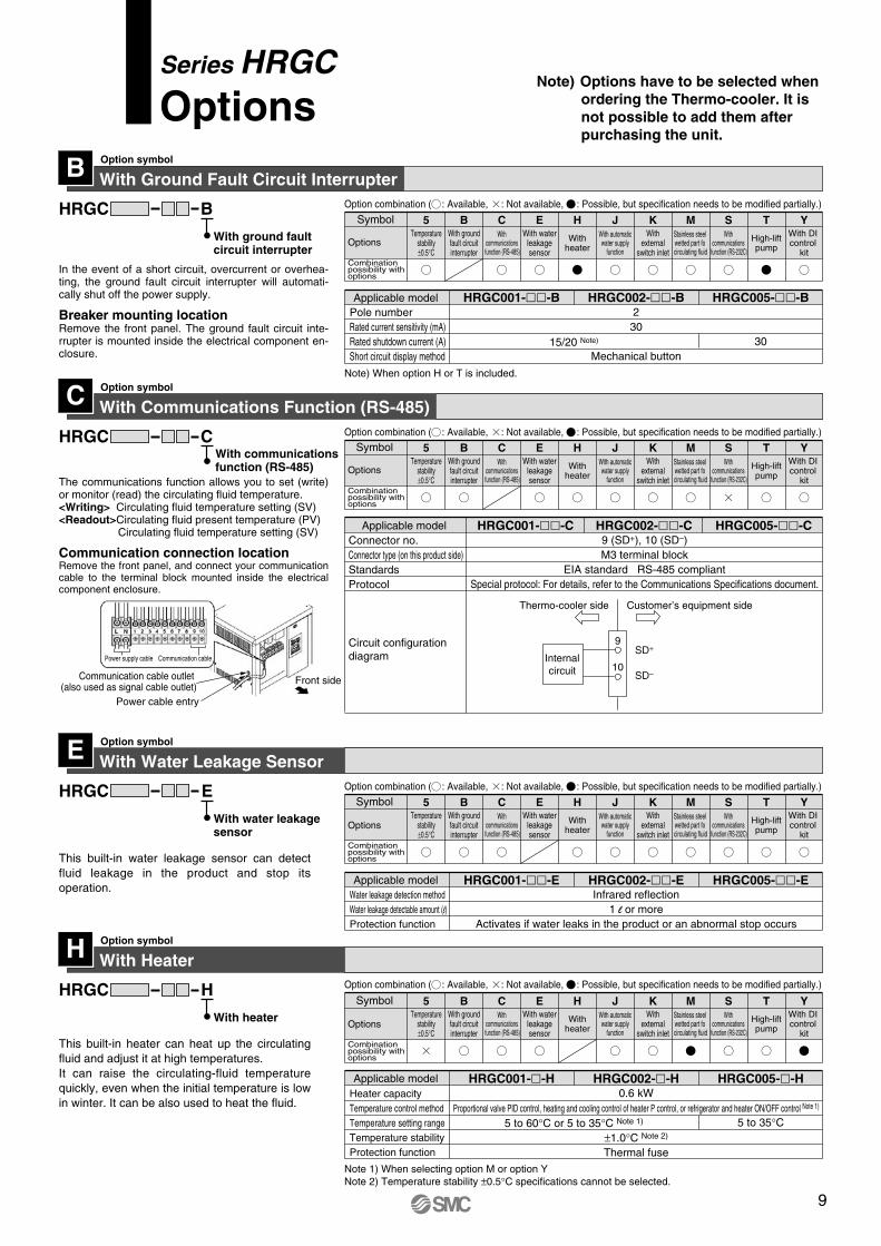
Series HRGCNote) Options have to be selected when
ordering the Thermo-cooler. It is not possible to add them after purchasing the unit.
With Ground Fault Circuit InterrupterOption symbolB
BHRGC
With ground fault circuit interrupter
Pole numberRated current sensitivity (mA)Rated shutdown current (A)Short circuit display method
302
15/20 Note) 30Mechanical button
HRGC001--B HRGC002--B HRGC005--BApplicable model
Symbol
Combination possibility with options
5 B C E H J K M S T Y
Symbol
Options
Combination possibility with options
5 B C E H J K M S T Y
With Communications Function (RS-485)Option symbolC
CHRGCWith communications function (RS-485)
Connector no.Connector type (on this product side)StandardsProtocol
Circuit configurationdiagram
9 (SD+), 10 (SD–)M3 terminal block
EIA standard RS-485 compliantSpecial protocol: For details, refer to the Communications Specifications document.
HRGC001--C HRGC002--C HRGC005--CApplicable model
9
10
SD+
SD–
Internalcircuit
Thermo-cooler side Customer’s equipment side
Series HRGCOptions
Power cable entry
Communication cable outlet (also used as signal cable outlet)
Power supply cable Communication cable
Front side
Note) When option H or T is included.
This built-in water leakage sensor can detect fluid leakage in the product and stop its operation.
With Water Leakage SensorOption symbolE
EHRGC
With water leakagesensor
Water leakage detection methodWater leakage detectable amount (l)Protection function
Infrared reflection1 l or more
Activates if water leaks in the product or an abnormal stop occurs
HRGC001--E HRGC002--E HRGC005--EApplicable model
Option combination ( : Available, : Not available, : Possible, but specification needs to be modified partially.)
Option combination ( : Available, : Not available, : Possible, but specification needs to be modified partially.)
Option combination ( : Available, : Not available, : Possible, but specification needs to be modified partially.)
Option combination ( : Available, : Not available, : Possible, but specification needs to be modified partially.)
Symbol
Options
Combination possibility with options
5 B C E H J K M S T Y
Symbol
Options
Combination possibility with options
5 B C E H J K M S T Y
This built-in heater can heat up the circulating fluid and adjust it at high temperatures. It can raise the circulating-fluid temperature quickly, even when the initial temperature is low in winter. It can be also used to heat the fluid.
With HeaterOption symbolH
HHRGC
With heater
Heater capacityTemperature control methodTemperature setting rangeTemperature stabilityProtection function
Proportional valve PID control, heating and cooling control of heater P control, or refrigerator and heater ON/OFF control Note 1)
0.6 kW
5 to 60°C or 5 to 35°C Note 1) 5 to 35°C±1.0°C Note 2)
Thermal fuse
HRGC001--H HRGC002--H HRGC005--HApplicable model
Note 1) When selecting option M or option YNote 2) Temperature stability ±0.5°C specifications cannot be selected.
The communications function allows you to set (write) or monitor (read) the circulating fluid temperature.<Writing> Circulating fluid temperature setting (SV)<Readout>Circulating fluid present temperature (PV)
Circulating fluid temperature setting (SV)
In the event of a short circuit, overcurrent or overhea-ting, the ground fault circuit interrupter will automati-cally shut off the power supply.
Breaker mounting locationRemove the front panel. The ground fault circuit inte-rrupter is mounted inside the electrical component en-closure.
Temperaturestability±0.5°C
With waterleakagesensor
With automaticwater supply
function
Withexternal
switch inlet
Stainless steelwetted part fo
circulating fluid
High-liftpump
With groundfault circuitinterrupter
With communications function (RS-485)
Withheater
With communications
function (RS-232C)
With DI control
kit
OptionsTemperature
stability±0.5°C
With waterleakagesensor
With automaticwater supply
function
Withexternal
switch inlet
Stainless steelwetted part fo
circulating fluid
High-liftpump
With groundfault circuitinterrupter
With communications function (RS-485)
Withheater
With communications
function (RS-232C)
With DI control
kit
Temperaturestability±0.5°C
With waterleakagesensor
With automaticwater supply
function
Withexternal
switch inlet
Stainless steelwetted part fo
circulating fluid
High-liftpump
With groundfault circuitinterrupter
With communications function (RS-485)
Withheater
With communications
function (RS-232C)
With DI control
kit
Communication connection locationRemove the front panel, and connect your communication cable to the terminal block mounted inside the electrical component enclosure.
8
Power cable(M3.5 thread)
Signal cable(M3 thread)
Power cable entry
Signal cable outletFront side
Other Features
Anti-freezing functionThis function detects the circulating fluid temperature. If the temperature approaches the freezing point, e.g. in winter at night, the pump operates automatically and the heat generated by the pump warms the circulating fluid, preventing freezing.
Input/output signal connection locationRemove the front panel, and connect a signal cable to the terminal block inside the electrical component enclosure.
M3 terminal block
Relay contact input (Remote start when the contact signal is closed, Remote stop when the contact signal is open.)
24 VDC±10% (Power supply is provided on the Thermo-cooler side.)
Max. 35 mA
1 (24 VDC), 2 (24 VCOM)
Relay contact output (When fault error (FAULT) occurs: open)
250 VAC, 1 A (Resistance load)
3, 4
Relay contact output (When operating: closed)
250 VAC, 1 A (Resistance load)
5, 6
Relay contact output (When warning error (WARN) occurs: open)
250 VAC, 1 A (Resistance load)
7, 8
EIA standard RS-485 compliant
Half duplex
Asynchronous communication
9, 10
Contact Input/Output Function
The thermo-cooler is standard-equipped with terminals that allow remote start/stop, and enable output of an operation signal, ab-normal status stop signal or alarm signal. These should be used for synchronising startup and shutdown with your other equip-ment, or when adding new warning lights or buzzers. However, the contact output volume is limited, so please add warning lights and/or buzzers for special relays (for amplification) if they are necessary.
Item
Connector type
Circuit diagram
Specifications
HRGC001 HRGC002 HRGC005
Note) Serial communication is optional. Refer to “Options” on page 9.
Remote operation signal input (Contact signal closed: chiller operation)
Thermo-cooler side
Terminal block (14 poles)
Customer’s equipment side
12
3
4
5
6
7
8
9
10SD+
SD–
24 VDC
24 VCOM3.9 kΩ
Abnormal status stop signal output (When fault error (FAULT) occurs: open)
Operation signal output (When operating: closed)
Alarm signal output (When warning error (WARN) occurs: open)
Communications function (RS-485)
Internalcircuit
Internalcircuit
Remoteoperationsignal input
Abnormal status stop signal output
Operationsignaloutput
Warning signaloutput
Communica-tions function(RS-485) Note)
Signal type
Input voltage range
Input current
Terminal number
Signal type
Contact capacity
Terminal number
Signal type
Contact capacity
Terminal number
Signal type
Contact capacity
Terminal number
Communication standard
Information orientation
Synchronisation method
Terminal number
Series HRGCNote) Options have to be selected when
ordering the Thermo-cooler. It is not possible to add them after purchasing the unit.
With Ground Fault Circuit InterrupterOption symbolB
BHRGC
With ground fault circuit interrupter
Pole numberRated current sensitivity (mA)Rated shutdown current (A)Short circuit display method
302
15/20 Note) 30Mechanical button
HRGC001--B HRGC002--B HRGC005--BApplicable model
Symbol
Combination possibility with options
5 B C E H J K M S T Y
Symbol
Options
Combination possibility with options
5 B C E H J K M S T Y
With Communications Function (RS-485)Option symbolC
CHRGCWith communications function (RS-485)
Connector no.Connector type (on this product side)StandardsProtocol
Circuit configurationdiagram
9 (SD+), 10 (SD–)M3 terminal block
EIA standard RS-485 compliantSpecial protocol: For details, refer to the Communications Specifications document.
HRGC001--C HRGC002--C HRGC005--CApplicable model
9
10
SD+
SD–
Internalcircuit
Thermo-cooler side Customer’s equipment side
Series HRGCOptions
Power cable entry
Communication cable outlet (also used as signal cable outlet)
Power supply cable Communication cable
Front side
Note) When option H or T is included.
This built-in water leakage sensor can detect fluid leakage in the product and stop its operation.
With Water Leakage SensorOption symbolE
EHRGC
With water leakagesensor
Water leakage detection methodWater leakage detectable amount (l)Protection function
Infrared reflection1 l or more
Activates if water leaks in the product or an abnormal stop occurs
HRGC001--E HRGC002--E HRGC005--EApplicable model
Option combination ( : Available, : Not available, : Possible, but specification needs to be modified partially.)
Option combination ( : Available, : Not available, : Possible, but specification needs to be modified partially.)
Option combination ( : Available, : Not available, : Possible, but specification needs to be modified partially.)
Option combination ( : Available, : Not available, : Possible, but specification needs to be modified partially.)
Symbol
Options
Combination possibility with options
5 B C E H J K M S T Y
Symbol
Options
Combination possibility with options
5 B C E H J K M S T Y
This built-in heater can heat up the circulating fluid and adjust it at high temperatures. It can raise the circulating-fluid temperature quickly, even when the initial temperature is low in winter. It can be also used to heat the fluid.
With HeaterOption symbolH
HHRGC
With heater
Heater capacityTemperature control methodTemperature setting rangeTemperature stabilityProtection function
Proportional valve PID control, heating and cooling control of heater P control, or refrigerator and heater ON/OFF control Note 1)
0.6 kW
5 to 60°C or 5 to 35°C Note 1) 5 to 35°C±1.0°C Note 2)
Thermal fuse
HRGC001--H HRGC002--H HRGC005--HApplicable model
Note 1) When selecting option M or option YNote 2) Temperature stability ±0.5°C specifications cannot be selected.
The communications function allows you to set (write) or monitor (read) the circulating fluid temperature.<Writing> Circulating fluid temperature setting (SV)<Readout>Circulating fluid present temperature (PV)
Circulating fluid temperature setting (SV)
In the event of a short circuit, overcurrent or overhea-ting, the ground fault circuit interrupter will automati-cally shut off the power supply.
Breaker mounting locationRemove the front panel. The ground fault circuit inte-rrupter is mounted inside the electrical component en-closure.
Temperaturestability±0.5°C
With waterleakagesensor
With automaticwater supply
function
Withexternal
switch inlet
Stainless steelwetted part fo
circulating fluid
High-liftpump
With groundfault circuitinterrupter
With communications function (RS-485)
Withheater
With communications
function (RS-232C)
With DI control
kit
Temperaturestability±0.5°C
With waterleakagesensor
With automaticwater supply
function
Withexternal
switch inlet
Stainless steelwetted part fo
circulating fluid
High-liftpump
With groundfault circuitinterrupter
With communications function (RS-485)
Withheater
With communications
function (RS-232C)
With DI control
kit
OptionsTemperature
stability±0.5°C
With waterleakagesensor
With automaticwater supply
function
Withexternal
switch inlet
Stainless steelwetted part fo
circulating fluid
High-liftpump
With groundfault circuitinterrupter
With communications function (RS-485)
Withheater
With communications
function (RS-232C)
With DI control
kit
Temperaturestability±0.5°C
With waterleakagesensor
With automaticwater supply
function
Withexternal
switch inlet
Stainless steelwetted part fo
circulating fluid
High-liftpump
With groundfault circuitinterrupter
With communications function (RS-485)
Withheater
With communications
function (RS-232C)
With DI control
kit
Communication connection locationRemove the front panel, and connect your communication cable to the terminal block mounted inside the electrical component enclosure.
9
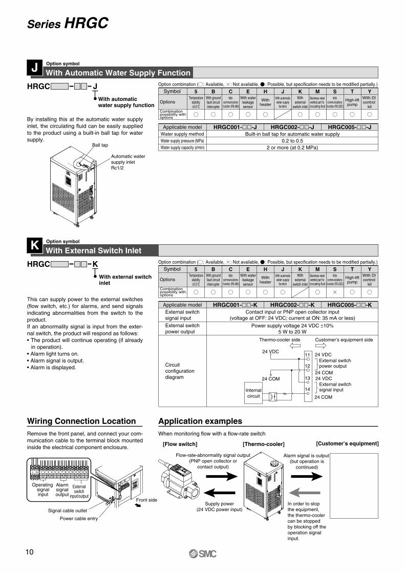
Symbol 5 B C E H J K M S T Y
With Automatic Water Supply FunctionOption symbol
By installing this at the automatic water supply inlet, the circulating fluid can be easily supplied to the product using a built-in ball tap for water supply.
JJHRGC
With automatic water supply function
Water supply methodWater supply pressure (MPa)Water supply capacity (l/min)
Built-in ball tap for automatic water supply0.2 to 0.5
2 or more (at 0.2 MPa)
HRGC001--J HRGC002--J HRGC005--JApplicable model
Ball tap
Automatic water supply inletRc1/2
With External Switch InletOption symbol
This can supply power to the external switches (flow switch, etc.) for alarms, and send signals indicating abnormalities from the switch to the product.If an abnormality signal is input from the exter-nal switch, the product will respond as follows:• The product will continue operating (if already
in operation).• Alarm light turns on.• Alarm signal is output.• Alarm is displayed.
KKHRGC
With external switch inlet
Circuitconfigurationdiagram
Power supply voltage 24 VDC ±10%5 W to 20 W
Contact input or PNP open collector input(voltage at OFF: 24 VDC; current at ON: 35 mA or less)
HRGC001--K HRGC002--K HRGC005--KApplicable model
External switchpower output
External switchsignal input
11
12
24 VDC
24 COM13
14
24 VDC
24 COM
Internalcircuit
External switchpower output
External switchsignal input
24 VDC
24 COM
Symbol 5 B C E H J K M S T Y
Signal cable outlet
Power cable entry
L N 1 2 3 4 5 6 7 8 9 10 13 1411 12
Externalswitch
input/output
Operating signalinput
Alarmsignaloutput
Front sideSupply power
(24 VDC power input)
Alarm signal is output (but operation is
continued)
[Thermo-cooler][Flow switch] [Customer’s equipment]
In order to stop the equipment, the thermo-cooler can be stopped by blocking off the operation signal input.
Wiring Connection LocationRemove the front panel, and connect your com-munication cable to the terminal block mounted inside the electrical component enclosure.
Application examplesWhen monitoring flow with a flow-rate switch
Thermo-cooler side Customer’s equipment side
Combination possibility with options
OptionsTemperature
stability±0.5°C
With waterleakagesensor
With automaticwater supply
function
Withexternal
switch inlet
Stainless steelwetted part fo
circulating fluid
High-liftpump
With groundfault circuitinterrupter
With communications function (RS-485)
Withheater
With communications
function (RS-232C)
With DI control
kit
Option combination ( : Available, : Not available, : Possible, but specification needs to be modified partially.)
Option combination ( : Available, : Not available, : Possible, but specification needs to be modified partially.)
Flow-rate-abnormality signal output (PNP open collector or
contact output)
Series HRGC
Stainless Steel Wetted Part for Circulating FluidOption symbol
By changing the material of the wetted part in the circulating-fluid circuit to stainless steel, deionised water with 2 MΩ or less of electrical resistance (0.5 µS/cm or more of electric con-ductivity) can be used. (However, heat exchan-ger is made of copper brazing.)
MMHRGC
Stainless steel wetted part for circulating fluid
Temperature setting rangeTemperature stabilityCirculating-fluid typeWetted part material for circulating fluid
5 to 35°C Note 1)
±1.0°C Note 2)
Clear water, Deionised water Note 3), Aqueous solution of 15% ethylene glycolStainless steel, Copper brazing (Heat exchanger), PVC
HRGC001--M HRGC002--M HRGC005--MApplicable model
With Communications Function (RS-232C)Option symbolS
SHRGC
Connector no.
StandardsProtocol
Connector type(on this product side)
Circuit configurationdiagram
9 (RD), 10 (SD), 11 (SG)
M3 terminal block
EIA standard RS-232C compliantSpecial protocol: For details, refer to the Communications Specifications document.
HRGC001--S HRGC002--S HRGC005--SApplicable model
Note 1) This cannot be used in circulating-fluid temperatures of 35°C or higher, even when option H is selected.
Note 2) Temperature stability ±0.5°C specifications cannot be selected.Note 3) Use deionised water with electrical resistance 2 MΩ·cm or less (electrical conductivity 0.5µS/cm
or more).
11 SG
Internalcircuit
10
9 RD
SD
Symbol 5 B C E H J K M S T Y
Symbol 5 B C E H J K M S T Y
Front side
L N 1 2 3 4 5 6 7 8 9 10 11
Thermo-cooler side Customer’s equipment side
Power cable entry
Communication cable outlet (also used as signal cable outlet)
Power supply cableSignal cable
With communications function (RS-232C)
With a host PC programmed in accordance with your manufacturing processor method, the communications function allows you to set (write) or monitor (read) the circulating fluid temperature.<Writing> Circulating fluid temperature setting (SV)<Readout>Circulating fluid present temperature (PV)
Circulating fluid temperature setting (SV)
Communication connection locationRemove the front panel, and connect your communication cable to the terminal block mounted inside the electrical component enclosure.
Combination possibility with options
OptionsTemperature
stability±0.5°C
With waterleakagesensor
With automaticwater supply
function
Withexternal
switch inlet
Stainless steelwetted part fo
circulating fluid
High-liftpump
With groundfault circuitinterrupter
With communications function (RS-485)
Withheater
With communications
function (RS-232C)
With DI control
kit
Option combination ( : Available, : Not available, : Possible, but specification needs to be modified partially.)
Thermo-cooler Series HRGC
10
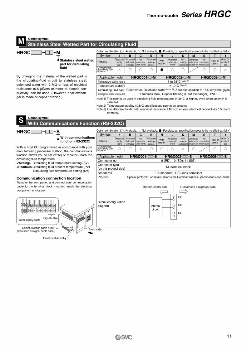
Symbol 5 B C E H J K M S T Y
With Automatic Water Supply FunctionOption symbol
By installing this at the automatic water supply inlet, the circulating fluid can be easily supplied to the product using a built-in ball tap for water supply.
JJHRGC
With automatic water supply function
Water supply methodWater supply pressure (MPa)Water supply capacity (l/min)
Built-in ball tap for automatic water supply0.2 to 0.5
2 or more (at 0.2 MPa)
HRGC001--J HRGC002--J HRGC005--JApplicable model
Ball tap
Automatic water supply inletRc1/2
With External Switch InletOption symbol
This can supply power to the external switches (flow switch, etc.) for alarms, and send signals indicating abnormalities from the switch to the product.If an abnormality signal is input from the exter-nal switch, the product will respond as follows:• The product will continue operating (if already
in operation).• Alarm light turns on.• Alarm signal is output.• Alarm is displayed.
KKHRGC
With external switch inlet
Circuitconfigurationdiagram
Power supply voltage 24 VDC ±10%5 W to 20 W
Contact input or PNP open collector input(voltage at OFF: 24 VDC; current at ON: 35 mA or less)
HRGC001--K HRGC002--K HRGC005--KApplicable model
External switchpower output
External switchsignal input
11
12
24 VDC
24 COM13
14
24 VDC
24 COM
Internalcircuit
External switchpower output
External switchsignal input
24 VDC
24 COM
Symbol 5 B C E H J K M S T Y
Signal cable outlet
Power cable entry
L N 1 2 3 4 5 6 7 8 9 10 13 1411 12
Externalswitch
input/output
Operating signalinput
Alarmsignaloutput
Front sideSupply power
(24 VDC power input)
Alarm signal is output (but operation is
continued)
[Thermo-cooler][Flow switch] [Customer’s equipment]
In order to stop the equipment, the thermo-cooler can be stopped by blocking off the operation signal input.
Wiring Connection LocationRemove the front panel, and connect your com-munication cable to the terminal block mounted inside the electrical component enclosure.
Application examplesWhen monitoring flow with a flow-rate switch
Thermo-cooler side Customer’s equipment side
Combination possibility with options
OptionsTemperature
stability±0.5°C
With waterleakagesensor
With automaticwater supply
function
Withexternal
switch inlet
Stainless steelwetted part fo
circulating fluid
High-liftpump
With groundfault circuitinterrupter
With communications function (RS-485)
Withheater
With communications
function (RS-232C)
With DI control
kit
Combination possibility with options
OptionsTemperature
stability±0.5°C
With waterleakagesensor
With automaticwater supply
function
Withexternal
switch inlet
Stainless steelwetted part fo
circulating fluid
High-liftpump
With groundfault circuitinterrupter
With communications function (RS-485)
Withheater
With communications
function (RS-232C)
With DI control
kit
Option combination ( : Available, : Not available, : Possible, but specification needs to be modified partially.)
Option combination ( : Available, : Not available, : Possible, but specification needs to be modified partially.)
Flow-rate-abnormality signal output (PNP open collector or
contact output)
Series HRGC
Stainless Steel Wetted Part for Circulating FluidOption symbol
By changing the material of the wetted part in the circulating-fluid circuit to stainless steel, deionised water with 2 MΩ or less of electrical resistance (0.5 µS/cm or more of electric con-ductivity) can be used. (However, heat exchan-ger is made of copper brazing.)
MMHRGC
Stainless steel wetted part for circulating fluid
Temperature setting rangeTemperature stabilityCirculating-fluid typeWetted part material for circulating fluid
5 to 35°C Note 1)
±1.0°C Note 2)
Clear water, Deionised water Note 3), Aqueous solution of 15% ethylene glycolStainless steel, Copper brazing (Heat exchanger), PVC
HRGC001--M HRGC002--M HRGC005--MApplicable model
With Communications Function (RS-232C)Option symbolS
SHRGC
Connector no.
StandardsProtocol
Connector type(on this product side)
Circuit configurationdiagram
9 (RD), 10 (SD), 11 (SG)
M3 terminal block
EIA standard RS-232C compliantSpecial protocol: For details, refer to the Communications Specifications document.
HRGC001--S HRGC002--S HRGC005--SApplicable model
Note 1) This cannot be used in circulating-fluid temperatures of 35°C or higher, even when option H is selected.
Note 2) Temperature stability ±0.5°C specifications cannot be selected.Note 3) Use deionised water with electrical resistance 2 MΩ·cm or less (electrical conductivity 0.5µS/cm
or more).
11 SG
Internalcircuit
10
9 RD
SD
Symbol 5 B C E H J K M S T Y
Symbol 5 B C E H J K M S T Y
Front side
L N 1 2 3 4 5 6 7 8 9 10 11
Thermo-cooler side Customer’s equipment side
Power cable entry
Communication cable outlet (also used as signal cable outlet)
Power supply cableSignal cable
With communications function (RS-232C)
With a host PC programmed in accordance with your manufacturing processor method, the communications function allows you to set (write) or monitor (read) the circulating fluid temperature.<Writing> Circulating fluid temperature setting (SV)<Readout>Circulating fluid present temperature (PV)
Circulating fluid temperature setting (SV)
Communication connection locationRemove the front panel, and connect your communication cable to the terminal block mounted inside the electrical component enclosure.
Combination possibility with options
OptionsTemperature
stability±0.5°C
With waterleakagesensor
With automaticwater supply
function
Withexternal
switch inlet
Stainless steelwetted part fo
circulating fluid
High-liftpump
With groundfault circuitinterrupter
With communications function (RS-485)
Withheater
With communications
function (RS-232C)
With DI control
kit
Option combination ( : Available, : Not available, : Possible, but specification needs to be modified partially.)
Combination possibility with options
OptionsTemperature
stability±0.5°C
With waterleakagesensor
With automaticwater supply
function
Withexternal
switch inlet
Stainless steelwetted part fo
circulating fluid
High-liftpump
With groundfault circuitinterrupter
With communications function (RS-485)
Withheater
With communications
function (RS-232C)
With DI control
kit
Option combination ( : Available, : Not available, : Possible, but specification needs to be modified partially.)
Thermo-cooler Series HRGC
11
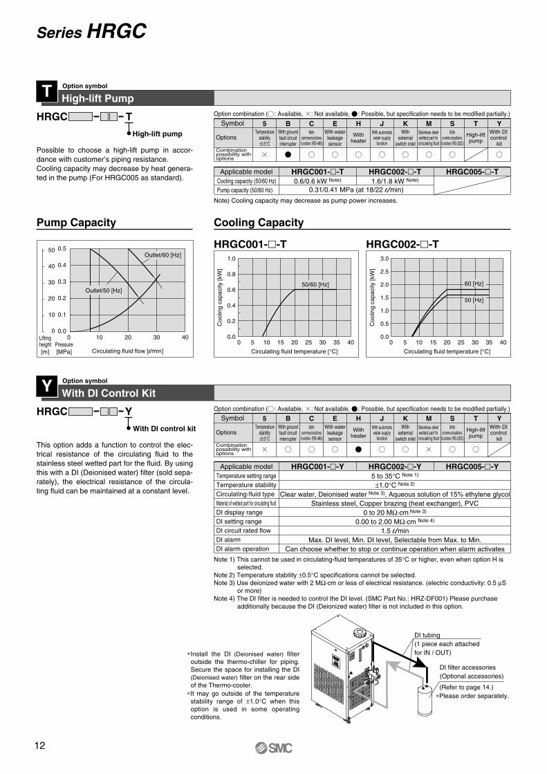
High-lift PumpOption symbol
Possible to choose a high-lift pump in accor-dance with customer’s piping resistance. Cooling capacity may decrease by heat genera-ted in the pump (For HRGC005 as standard).
TTHRGC
High-lift pump
Cooling capacity (50/60 Hz)Pump capacity (50/60 Hz)
0.6/0.6 kW Note)
0.31/0.41 MPa (at 18/22 l/min)1.6/1.8 kW Note)
HRGC001--T HRGC002--T HRGC005--TApplicable model
With DI Control KitOption symbol
This option adds a function to control the elec-trical resistance of the circulating fluid to the stainless steel wetted part for the fluid. By using this with a DI (Deionised water) filter (sold sepa-rately), the electrical resistance of the circula-ting fluid can be maintained at a constant level.
YYHRGC
With DI control kit
Temperature setting rangeTemperature stabilityCirculating-fluid typeMaterial of wetted part for circulating fluidDI display rangeDI setting rangeDI circuit rated flowDI alarmDI alarm operation
5 to 35°C Note 1)
±1.0°C Note 2)
Clear water, Deionised water Note 3), Aqueous solution of 15% ethylene glycolStainless steel, Copper brazing (heat exchanger), PVC
0 to 20 MΩ·cm Note 3)
0.00 to 2.00 MΩ·cm Note 4)
1.5 l/minMax. DI level, Min. DI level, Selectable from Max. to Min.
Can choose whether to stop or continue operation when alarm activates
HRGC001--Y HRGC002--Y HRGC005--YApplicable model
Note) Cooling capacity may decrease as pump power increases.
Note 1) This cannot be used in circulating-fluid temperatures of 35°C or higher, even when option H is selected.
Note 2) Temperature stability ±0.5°C specifications cannot be selected.Note 3) Use deionized water with 2 MΩ·cm or less of electrical resistance. (electric conductivity: 0.5 µS
or more)Note 4) The DI filter is needed to control the DI level. (SMC Part No.: HRZ-DF001) Please purchase
additionally because the DI (Deionized water) filter is not included in this option.
Symbol 5 B C E H J K M S T Y
Symbol 5 B C E H J K M S T Y
Pump Capacity Cooling Capacity
DI tubing(1 piece each attachedfor IN / OUT)
DI filter accessories(Optional accessories)
0.5
0.4
0.3
0.2
0.1
0.00 10 20 30 40
Circulating fluid flow [l/min]Pressure[MPa]
Outlet/60 [Hz]
Outlet/50 [Hz]
Liftingheight[m]
50
40
30
20
10
0
∗Install the DI (Deionised water) filter outside the thermo-chiller for piping. Secure the space for installing the DI (Deionised water) filter on the rear side of the Thermo-cooler.
∗It may go outside of the temperature stability range of ±1.0°C when this option is used in some operating conditions.
HRGC001--T HRGC002--T3.0
2.5
2.0
1.5
1.0
0.5
0.00 5 10 15 20 25 30 35 40
Circulating fluid temperature [°C]
Coo
ling
capa
city
[kW
]
60 [Hz]
50 [Hz]
1.0
0.8
0.6
0.4
0.2
0.00 5 10 15 20 25 30 35 40
Circulating fluid temperature [°C]
Coo
ling
capa
city
[kW
]
50/60 [Hz]
(Refer to page 14.)∗Please order separately.
Combination possibility with options
OptionsTemperature
stability±0.5°C
With waterleakagesensor
With automaticwater supply
function
Withexternal
switch inlet
Stainless steelwetted part fo
circulating fluid
High-liftpump
With groundfault circuitinterrupter
With communications function (RS-485)
Withheater
With communications
function (RS-232C)
With DI control
kit
Option combination ( : Available, : Not available, : Possible, but specification needs to be modified partially.)
Series HRGC
Loop tape(Surface fastener with adhesive tape backing)
q Dustproof filter (with surface fastener and hook tape)
w Affix to external panel.
e Press on to secure the dustproof filter.
Part no.HRGC-BP001(G)HRGC-BP005(G)
275300
Connection thread
Connection thread
Connection thread
Connection thread
195210
A B110110
C130130
D140140
E200200
F210210
G(mm)
Relief valve
Pressure gauge
Nipples
Unions
(10)
(25)
(25)
B
A
(10)
B
A(25) (25)
A
Circ
ulat
ing-
fluid
pre
ssur
e-re
lief d
irect
ion
BC
E
FG
D
Series HRGCOptional Accessories 1
Note) Please order separately. Necessary to be fitted by the customer.
Prevents performance degradation when using air-cooled refrigeration Thermo-coolers in dusty or contaminated en-vironments.
• Maximum ambient temperature: 40°C
This prevents the occurrence of pump overload that exceeds the maximum operating pressure of the Thermo-cooler at low flow rate.
• Use circulating fluid in 5 to 60°C temperature range
Dustproof Filter Set
FLHRGC
Symbol
001 005
Applicable Thermo-coolers Quantity per setApplicable Thermo-coolers
By-pass Piping Set
Symbol
001
001G
005
005G
HRGC001-HRGC002-HRGC001-HRGC002-HRGC005-
HRGC00--T
HRGC005-HRGC00--T
Applicable Thermo-coolers Wetted part material
PTFE,Stainless steel
Pressure setting range (50/60 Hz) Note)
0.22 to 0.48/0.29 to 0.48 MPa
Applicable Thermo-coolers
Note) The pressure of the by-pass piping set can be adjusted by the customer.
Bronze, PTFE,Stainless steel
Bronze, PTFE,Stainless steel
PTFE,Stainless steel
0.12 to 0.13/0.16 to 0.18 MPa
BPHRGC
Dimensions
How to Order How to Order
Mounting Exampleq This dustproof filter is secured with hook-and-loop tape.
This is sewed onto the male side of the surface fastener, and has adhesive tape backing for fixing to the female si-de.
w Remove the paper covering of the adhesive tape and affix the loop tape to the external panel of the ventilation hole on the Thermo-cooler.
e Simply press the hook tape on to the loop tape to mount the dustproof filter.
Mounting ExampleA pressure relief valve and pressure gauge can be mounted on the body with unions and nipples.
HRGC-FL005HRGC-FL001
Dimensions
HRGC-BP001(G)HRGC-BP005(G)
HRGC001-AHRGC002-AHRGC005-A
1
1
Part no.HRGC-FL001HRGC-FL005
475430
310530
A B11
Quantity per set(mm)
12
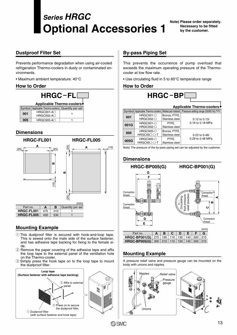
High-lift PumpOption symbol
Possible to choose a high-lift pump in accor-dance with customer’s piping resistance. Cooling capacity may decrease by heat genera-ted in the pump (For HRGC005 as standard).
TTHRGC
High-lift pump
Cooling capacity (50/60 Hz)Pump capacity (50/60 Hz)
0.6/0.6 kW Note)
0.31/0.41 MPa (at 18/22 l/min)1.6/1.8 kW Note)
HRGC001--T HRGC002--T HRGC005--TApplicable model
With DI Control KitOption symbol
This option adds a function to control the elec-trical resistance of the circulating fluid to the stainless steel wetted part for the fluid. By using this with a DI (Deionised water) filter (sold sepa-rately), the electrical resistance of the circula-ting fluid can be maintained at a constant level.
YYHRGC
With DI control kit
Temperature setting rangeTemperature stabilityCirculating-fluid typeMaterial of wetted part for circulating fluidDI display rangeDI setting rangeDI circuit rated flowDI alarmDI alarm operation
5 to 35°C Note 1)
±1.0°C Note 2)
Clear water, Deionised water Note 3), Aqueous solution of 15% ethylene glycolStainless steel, Copper brazing (heat exchanger), PVC
0 to 20 MΩ·cm Note 3)
0.00 to 2.00 MΩ·cm Note 4)
1.5 l/minMax. DI level, Min. DI level, Selectable from Max. to Min.
Can choose whether to stop or continue operation when alarm activates
HRGC001--Y HRGC002--Y HRGC005--YApplicable model
Note) Cooling capacity may decrease as pump power increases.
Note 1) This cannot be used in circulating-fluid temperatures of 35°C or higher, even when option H is selected.
Note 2) Temperature stability ±0.5°C specifications cannot be selected.Note 3) Use deionized water with 2 MΩ·cm or less of electrical resistance. (electric conductivity: 0.5 µS
or more)Note 4) The DI filter is needed to control the DI level. (SMC Part No.: HRZ-DF001) Please purchase
additionally because the DI (Deionized water) filter is not included in this option.
Symbol 5 B C E H J K M S T Y
Symbol 5 B C E H J K M S T Y
Pump Capacity Cooling Capacity
DI tubing(1 piece each attachedfor IN / OUT)
DI filter accessories(Optional accessories)
0.5
0.4
0.3
0.2
0.1
0.00 10 20 30 40
Circulating fluid flow [l/min]Pressure[MPa]
Outlet/60 [Hz]
Outlet/50 [Hz]
Liftingheight[m]
50
40
30
20
10
0
∗Install the DI (Deionised water) filter outside the thermo-chiller for piping. Secure the space for installing the DI (Deionised water) filter on the rear side of the Thermo-cooler.
∗It may go outside of the temperature stability range of ±1.0°C when this option is used in some operating conditions.
HRGC001--T HRGC002--T3.0
2.5
2.0
1.5
1.0
0.5
0.00 5 10 15 20 25 30 35 40
Circulating fluid temperature [°C]
Coo
ling
capa
city
[kW
]
60 [Hz]
50 [Hz]
1.0
0.8
0.6
0.4
0.2
0.00 5 10 15 20 25 30 35 40
Circulating fluid temperature [°C]
Coo
ling
capa
city
[kW
]
50/60 [Hz]
(Refer to page 14.)∗Please order separately.
Combination possibility with options
OptionsTemperature
stability±0.5°C
With waterleakagesensor
With automaticwater supply
function
Withexternal
switch inlet
Stainless steelwetted part fo
circulating fluid
High-liftpump
With groundfault circuitinterrupter
With communications function (RS-485)
Withheater
With communications
function (RS-232C)
With DI control
kit
Option combination ( : Available, : Not available, : Possible, but specification needs to be modified partially.)
Combination possibility with options
OptionsTemperature
stability±0.5°C
With waterleakagesensor
With automaticwater supply
function
Withexternal
switch inlet
Stainless steelwetted part fo
circulating fluid
High-liftpump
With groundfault circuitinterrupter
With communications function (RS-485)
Withheater
With communications
function (RS-232C)
With DI control
kit
Option combination ( : Available, : Not available, : Possible, but specification needs to be modified partially.)
Series HRGC
Loop tape(Surface fastener with adhesive tape backing)
q Dustproof filter (with surface fastener and hook tape)
w Affix to external panel.
e Press on to secure the dustproof filter.
Part no.HRGC-BP001(G)HRGC-BP005(G)
275300
Connection thread
Connection thread
Connection thread
Connection thread
195210
A B110110
C130130
D140140
E200200
F210210
G(mm)
Relief valve
Pressure gauge
Nipples
Unions
(10)
(25)
(25)
B
A
(10)
B
A(25) (25)
A
Circ
ulat
ing-
fluid
pre
ssur
e-re
lief d
irect
ion
BC
E
FG
D
Series HRGCOptional Accessories 1
Note) Please order separately. Necessary to be fitted by the customer.
Prevents performance degradation when using air-cooled refrigeration Thermo-coolers in dusty or contaminated en-vironments.
• Maximum ambient temperature: 40°C
This prevents the occurrence of pump overload that exceeds the maximum operating pressure of the Thermo-cooler at low flow rate.
• Use circulating fluid in 5 to 60°C temperature range
Dustproof Filter Set
FLHRGC
Symbol
001 005
Applicable Thermo-coolers Quantity per setApplicable Thermo-coolers
By-pass Piping Set
Symbol
001
001G
005
005G
HRGC001-HRGC002-HRGC001-HRGC002-HRGC005-
HRGC00--T
HRGC005-HRGC00--T
Applicable Thermo-coolers Wetted part material
PTFE,Stainless steel
Pressure setting range (50/60 Hz) Note)
0.22 to 0.48/0.29 to 0.48 MPa
Applicable Thermo-coolers
Note) The pressure of the by-pass piping set can be adjusted by the customer.
Bronze, PTFE,Stainless steel
Bronze, PTFE,Stainless steel
PTFE,Stainless steel
0.12 to 0.13/0.16 to 0.18 MPa
BPHRGC
Dimensions
How to Order How to Order
Mounting Exampleq This dustproof filter is secured with hook-and-loop tape.
This is sewed onto the male side of the surface fastener, and has adhesive tape backing for fixing to the female si-de.
w Remove the paper covering of the adhesive tape and affix the loop tape to the external panel of the ventilation hole on the Thermo-cooler.
e Simply press the hook tape on to the loop tape to mount the dustproof filter.
Mounting ExampleA pressure relief valve and pressure gauge can be mounted on the body with unions and nipples.
HRGC-FL005HRGC-FL001
Dimensions
HRGC-BP001(G)HRGC-BP005(G)
HRGC001-AHRGC002-AHRGC005-A
1
1
Part no.HRGC-FL001HRGC-FL005
475430
310530
A B11
Quantity per set(mm)
13

Series HRGCOptional Accessories 2
DI (Deionised Water) Filter
Part no.
HRZ-DF001
Applicable model
Common for all models which can selectthe DI control kit. (Option “Y”)
Note) The DI (Deionised Water) filters are consumable. Depending on the status (electrical resistivity set value, circulating fluid temperature, piping volume, etc.), product life cycles will vary accordingly.
Insulating Material for DI (Deionized Water) Filter
Part no.
HRZ-DF002
Applicable model
Common for all models which can selectthe DI control kit. (Option “Y”)
Approx.ø220 mm
App
rox.
508
mm
Weight: Approx. 20 kg
Note) Please order separately. Necessary to be fitted by the customer.
This is the ion replacement resin to maintain the electrical resistivity of the circulating fluid.Customers who selected the DI control kit (Option “Y”) need to purchase the DI (Deionised water) filter separately.
When the DI (Deionized Water) filter is used at a high-temperature, we recommend that you use this insulating material to protect the radiated heat from the DI (Deionized Water) filter or possible burns. When the DI filter is used at a low-temperature, we also recommend that you use this to prevent heat absorption from the DI filter and to avoid forming condensation.
Series HRGCSpecific Product Precautions 1Be sure to read this before handling. Refer to the back cover for Safety Instructions and “Handling Precautions for SMC Products” (M-E03-3) for Temperature Control Equipment Precautions.
Design
Warning1. This catalogue shows the specification of a single unit.
1. Confirm the specification of the single unit (contents of this catalogue) and thoroughly consider the adaptability between the customer’s system and this unit.
2. Although the protection circuit as a single unit is installed, prepare a drain pan, water leakage sensor, discharge air facility, and emer-gency stop equipment, depending on the customer’s operating con-dition. Also, the customer is requested to carry out the safety design for the whole system.
2. When attempting to cool areas that are open to the atmosphere (tanks, pipes), plan your piping system accordingly.When cooling open-air external tanks, arrange the piping so that there are coil pipes for cooling inside the tanks, and to carry back the entire flow volume of circulating fluid that is released.
1. Model selection For selecting a model of Thermo-cooler, it is required to know the heat generation amount of a customer’s equipment.Obtain the heat generation amount, referring to the model selection example for the HRGC series before selecting a model.
2. Indication of model numberSelect the cooling method and temperature stability depending on the customer’s application.
1. Thoroughly read the operating manual. Read the operating manual completely before operation, and keep a copy on-site, for future reference.
1. Do not use in the following environments because it will lead to a breakdown. 1. Environment like described in “Temperature Control Equipment Pre-
cautions”.2. Locations where spatter will adhere to when welding.3. Locations where it is likely that the leakage of flammable gas may oc-
cur.4. Locations having a large quantity of dust.
If it is necessary to use the unit in an environment where there is a risk of the fin portion of the air-condenser becoming clogged, use the dustproof filter set (sold separately).
5. A place in which water freezes. If such an environment is unavoida-ble, please contact SMC.
2. Install in an environment where the unit will not come into direct contact with rain or snow.(HRGC001 to HRGC005)These models are for indoor use only.Do not install outdoors where rain or snow may fall on them.
3. Conduct ventilation and cooling to discharge heat.(Air-cooled refrigeration)The heat which is cooled down through an air-cooled condenser is dis-charged. When using in a room which is shut tightly, the ambient temperature will exceed the specification range stipulated in this catalogue, which will activate the safety detector and stop the operation.In order to avoid this situation, discharge the heat outside of a room by ventilation or cooling facilities.
4. The Thermo-cooler is not designed for a clean room. It ge-nerates particles internally.
1. Avoid oil or other foreign objects entering the circulating fluid.
2. Use an ethylene glycol aqueous solution that does not contain additives (such as preservatives, etc.).
Selection
Warning
Handling
Warning
Operating Environment / Storage Environment
Warning
Circulating Fluid
Caution3. The concentration of ethylene glycol aqueous solution
must be 15% or less. Overly high concentration aqueous solution will overload to the pump and activates the safety interlock, which may stop the operation. On the other hand, if the concentration is too low, the aqueous solution freezes at low temperature, which may cause malfunction in the product.
4. When using clear water as a circulating fluid, use water that conforms to the appropriate water quality standards.Use clear water (including diluted ethylene glycol aqueous solution) that satisfies the quality standard shown below.
5. Deionised wate can be used (as supply water), but resisti-vity cannot be maintained.When supplying water, use deionised water with electrical conductivity of 1 µS/cm or more (electrical resistivity: 1 MΩ·cm or less). However, since components of the wetted part will be released in water, electro-lyte concentration cannot be maintained.
(HRGC001/002)1. A magnet pump is used as a circulating pump for the circulating liquid.
It is particularly impossible to use liquid including metallic powder such as iron powder.
1. Transportation by forklift (HRGC001 to HRGC005)1. A licensed driver should drive the forklift.2. The proper place to insert the tines of the forklift differs depending on
the model of cooler. Check the operating manual to confirm, and be sure to drive the fork in far enough for it to come out the other side.
3. Be careful not to bump the fork to the cover panel or piping ports.
2. Hanging transportation (HRGC005)1. Crane manipulation and slinging work should be done by an eligible person.2. Do not grip the piping or the handles of the panel on the right side.3. When hanging by the eye bolts, be sure to use a 4-point hanging met-
hod. For the hanging angle, use caution regarding the position of the centre of gravity and hold it within 60°.
3. Transporting using casters1. This product is heavy and should be moved by at least two people.2. Do not grip the piping port on the right side or the handles of the panel.3. When transporting using a forklift, be sure not to let it hit the casters
or adjusters, and drive the fork all the way through until it comes out the other side.
∗ In the case of [MΩ cm], it will be 0.003 to 0.01.
Standarditem
Referenceitem
ItempH (at 25°C)Electrical conductivity (25°C)Chloride ion (Cl–)Sulfuric acid ion (SO4
2–)Acid consumption amount (at pH4.8)Total hardness Calcium hardness (CaCO3)Ionic state silica (SiO2)Iron (Fe)Copper (Cu)Sulfide ion (S2
–)Ammonium ion (NH4
+)Residual chlorine (Cl)Free carbon (CO2)
Unit—
[µS/cm][mg/L][mg/L][mg/L][mg/L][mg/L][mg/L][mg/L][mg/L][mg/L][mg/L][mg/L][mg/L]
Standard value6.8 to 8.0
100∗ to 300∗50 or less50 or less50 or less70 or less50 or less30 or less0.3 or less0.1 or less
Should not be detected.0.1 or less0.3 or less4.0 or less
The Japan Refrigeration and Air Conditioning Industry AssociationJRA GL-02-1994 “Cooling water system – Circulation type – Make-up water”
Clean Water (as Circulating Fluid) Quality Standard
Transportation / Transfer / Movement
Warning
HRGC001, HRGC002 HRGC005
Circulating Fluid
Fork insertionside
Fork insertionside
60° or lessHanging position
Fork insertionside Fork
insertionside
Fork insertionside
Fork insertionsideCaution
14
Series HRGCOptional Accessories 2
DI (Deionised Water) Filter
Part no.
HRZ-DF001
Applicable model
Common for all models which can selectthe DI control kit. (Option “Y”)
Note) The DI (Deionised Water) filters are consumable. Depending on the status (electrical resistivity set value, circulating fluid temperature, piping volume, etc.), product life cycles will vary accordingly.
Insulating Material for DI (Deionized Water) Filter
Part no.
HRZ-DF002
Applicable model
Common for all models which can selectthe DI control kit. (Option “Y”)
Approx.ø220 mm
App
rox.
508
mm
Weight: Approx. 20 kg
Note) Please order separately. Necessary to be fitted by the customer.
This is the ion replacement resin to maintain the electrical resistivity of the circulating fluid.Customers who selected the DI control kit (Option “Y”) need to purchase the DI (Deionised water) filter separately.
When the DI (Deionized Water) filter is used at a high-temperature, we recommend that you use this insulating material to protect the radiated heat from the DI (Deionized Water) filter or possible burns. When the DI filter is used at a low-temperature, we also recommend that you use this to prevent heat absorption from the DI filter and to avoid forming condensation.
Series HRGCSpecific Product Precautions 1Be sure to read this before handling. Refer to the back cover for Safety Instructions and “Handling Precautions for SMC Products” (M-E03-3) for Temperature Control Equipment Precautions.
Design
Warning1. This catalogue shows the specification of a single unit.
1. Confirm the specification of the single unit (contents of this catalogue) and thoroughly consider the adaptability between the customer’s system and this unit.
2. Although the protection circuit as a single unit is installed, prepare a drain pan, water leakage sensor, discharge air facility, and emer-gency stop equipment, depending on the customer’s operating con-dition. Also, the customer is requested to carry out the safety design for the whole system.
2. When attempting to cool areas that are open to the atmosphere (tanks, pipes), plan your piping system accordingly.When cooling open-air external tanks, arrange the piping so that there are coil pipes for cooling inside the tanks, and to carry back the entire flow volume of circulating fluid that is released.
1. Model selection For selecting a model of Thermo-cooler, it is required to know the heat generation amount of a customer’s equipment.Obtain the heat generation amount, referring to the model selection example for the HRGC series before selecting a model.
2. Indication of model numberSelect the cooling method and temperature stability depending on the customer’s application.
1. Thoroughly read the operating manual. Read the operating manual completely before operation, and keep a copy on-site, for future reference.
1. Do not use in the following environments because it will lead to a breakdown. 1. Environment like described in “Temperature Control Equipment Pre-
cautions”.2. Locations where spatter will adhere to when welding.3. Locations where it is likely that the leakage of flammable gas may oc-
cur.4. Locations having a large quantity of dust.
If it is necessary to use the unit in an environment where there is a risk of the fin portion of the air-condenser becoming clogged, use the dustproof filter set (sold separately).
5. A place in which water freezes. If such an environment is unavoida-ble, please contact SMC.
2. Install in an environment where the unit will not come into direct contact with rain or snow.(HRGC001 to HRGC005)These models are for indoor use only.Do not install outdoors where rain or snow may fall on them.
3. Conduct ventilation and cooling to discharge heat.(Air-cooled refrigeration)The heat which is cooled down through an air-cooled condenser is dis-charged. When using in a room which is shut tightly, the ambient temperature will exceed the specification range stipulated in this catalogue, which will activate the safety detector and stop the operation.In order to avoid this situation, discharge the heat outside of a room by ventilation or cooling facilities.
4. The Thermo-cooler is not designed for a clean room. It ge-nerates particles internally.
1. Avoid oil or other foreign objects entering the circulating fluid.
2. Use an ethylene glycol aqueous solution that does not contain additives (such as preservatives, etc.).
Selection
Warning
Handling
Warning
Operating Environment / Storage Environment
Warning
Circulating Fluid
Caution3. The concentration of ethylene glycol aqueous solution
must be 15% or less. Overly high concentration aqueous solution will overload to the pump and activates the safety interlock, which may stop the operation. On the other hand, if the concentration is too low, the aqueous solution freezes at low temperature, which may cause malfunction in the product.
4. When using clear water as a circulating fluid, use water that conforms to the appropriate water quality standards.Use clear water (including diluted ethylene glycol aqueous solution) that satisfies the quality standard shown below.
5. Deionised wate can be used (as supply water), but resisti-vity cannot be maintained.When supplying water, use deionised water with electrical conductivity of 1 µS/cm or more (electrical resistivity: 1 MΩ·cm or less). However, since components of the wetted part will be released in water, electro-lyte concentration cannot be maintained.
(HRGC001/002)1. A magnet pump is used as a circulating pump for the circulating liquid.
It is particularly impossible to use liquid including metallic powder such as iron powder.
1. Transportation by forklift (HRGC001 to HRGC005)1. A licensed driver should drive the forklift.2. The proper place to insert the tines of the forklift differs depending on
the model of cooler. Check the operating manual to confirm, and be sure to drive the fork in far enough for it to come out the other side.
3. Be careful not to bump the fork to the cover panel or piping ports.
2. Hanging transportation (HRGC005)1. Crane manipulation and slinging work should be done by an eligible person.2. Do not grip the piping or the handles of the panel on the right side.3. When hanging by the eye bolts, be sure to use a 4-point hanging met-
hod. For the hanging angle, use caution regarding the position of the centre of gravity and hold it within 60°.
3. Transporting using casters1. This product is heavy and should be moved by at least two people.2. Do not grip the piping port on the right side or the handles of the panel.3. When transporting using a forklift, be sure not to let it hit the casters
or adjusters, and drive the fork all the way through until it comes out the other side.
∗ In the case of [MΩ cm], it will be 0.003 to 0.01.
Standarditem
Referenceitem
ItempH (at 25°C)Electrical conductivity (25°C)Chloride ion (Cl–)Sulfuric acid ion (SO4
2–)Acid consumption amount (at pH4.8)Total hardness Calcium hardness (CaCO3)Ionic state silica (SiO2)Iron (Fe)Copper (Cu)Sulfide ion (S2
–)Ammonium ion (NH4
+)Residual chlorine (Cl)Free carbon (CO2)
Unit—
[µS/cm][mg/L][mg/L][mg/L][mg/L][mg/L][mg/L][mg/L][mg/L][mg/L][mg/L][mg/L][mg/L]
Standard value6.8 to 8.0
100∗ to 300∗50 or less50 or less50 or less70 or less50 or less30 or less0.3 or less0.1 or less
Should not be detected.0.1 or less0.3 or less4.0 or less
The Japan Refrigeration and Air Conditioning Industry AssociationJRA GL-02-1994 “Cooling water system – Circulation type – Make-up water”
Clean Water (as Circulating Fluid) Quality Standard
Transportation / Transfer / Movement
Warning
HRGC001, HRGC002 HRGC005
Circulating Fluid
Fork insertionside
Fork insertionside
60° or lessHanging position
Fork insertionside Fork
insertionside
Fork insertionside
Fork insertionsideCaution
15
Piping
Caution
Electrical Wiring
Warning
Caution
Facility Water Supply
Warning
Caution
Mounting / Installation
Warning1. Do not place heavy objects on top of this product or step on it.
The external panel can be deformed and danger can result.
2. Do not directly touch the edge of the external panel when removing and installing it. It may cause injury. Be sure to wear protective gloves.
3. Lower the adjusters and do not move. Be sure to lower all four adjusters to the level of the floor.
M3M4M5M6
0.63 1.5 3 5.2
Connection thread
Applicable tightening torque N m
M8M10M12
12.524.542
Connection thread
Applicable tightening torque N m
Fixing Threads Tightening Torque
Piping
Caution
Operation
Warning
1. Install on a rigid floor which can withstand this product’s weight.
2. Secure with bolts, anchor bolts, etc.Fasteners such as bolts or anchor bolts should be tighten with the re-commended torque shown below.
(When using optional accessories/dustproof filter set)1. Use the attached surface fastener (with adhesive tape) to
affix the dustproof filter to the panel of the Thermo-cooler.2. Mounting the filter will create a certain amount of resistan-
ce to ventilation that will reduce the volume of airflow.For this reason, be sure to keep the ambient temperature at 40°C or less.
3. Depending on the installation height of the Thermo-cooler and/or the cooled substrates, the circulating fluid may overflow from the tank lid or overflow outlet.In particular, avoid overflow from the lid of the built-in tank by installing with a height difference of 10 m or less.Be sure to pipe the overflow outlet to a wastewater collection pit, etc.
1. Regarding the circulating fluid pipings, consider carefully the suitability for shutoff pressure, temperature and circu-lating fluid. If the operating performance is not sufficient, the pipings may burst du-ring operation.
2. For the circulating fluid pipings, use clean pipings which have no dust, piping debris or other foreign objects inside the pipings, and blow with air prior to undertaking any pi-ping works. If piping debris or other foreign objects remain inside the circulating fluid circuit, it can result in blockage, insufficient cooling or damage to the pump impeller.
3. Select the piping port size which can exceed the rated flow.For the rated flow, refer to the pump capacity table.
4. When tightening at the circulating fluid inlets and outlets, tank drain port or overflow outlet of this product, use a pi-pe wrench to clamp the connection ports.
5. For the circulating fluid piping connection, install a drain pan and wastewater collection pit just in case the circula-ting fluid leaks.
6. While cleaning the inside of the tank, attach a valve to the tank drain outlet to drain the circulating fluid (clear water).
7. This product series consists of circulating fluid temperatu-re controllers with built-in tanks. Do not install equipment on your system side such as pumps that for-cibly return the circulating fluid to the unit. Also, if you attach an external tank that is open to the air, it may become impossible to circulate the cir-culating fluid. Proceed with caution.
(Water-cooled refrigeration HRGC-W)1. When tightening the facility water inlets and outlets of this
product, use a pipe wrench to clamp the connection ports.2. Install by-pass piping.
This product has a built-in water control valve, so when the refrigeration circuit is stopped, facility water does not flow out in order to save energy.For this reason, by-pass piping is necessary for conducting maintenan-ce of your facility water equipment, so be sure to install it.
1. Never change the set value of the safety instrument. If the set value is changed, it will likely cause a breakdown or cause the product to catch on fire.
2. Before wiring, be sure to cut the power supply. Never perform any job while the product is energised.
3. Secure the cable so that its force, etc. is not applied to the terminal connector parts. When the connection or attachment is incomplete, it will likely lead to an electrical shock, a fire, etc.
4. Grounding should never be connected to a water line, gas line or lightning rod.
5. Multiple wiring is dangerous because it will lead to heat ge-neration or cause a fire.
1. Power supply, signal cable and connecting terminal should be prepared by the customer.
(When using the HRGC--C with optional communications function)1. Communication cables and adapters should be prepared
by the customer.Prepare parts that conform to the connector specifications of your host computer.
2. Pay attention to the polarity when connecting communication cables.
(Water-cooled refrigeration HRGC-W)1. Before startup, be sure to open the valve of your facility
water equipment.Prepare before startup, so that facility water can flow when the fitted wa-ter control valve (facility water control valve) opens during operation.
2. Supply pressure should be 0.5 MPa or less. When the supply pressure is high, it will cause water leakage.
3. Be sure to prepare your utilities so that the pressure of the Thermo-cooler facility water outlet is at 0 MPa (atmosphe-ric pressure) or more.If the facility water outlet pressure becomes negative, the internal facility water piping may collapse, and proper flow control of facility water will be impossible.
1. Confirmation before operation 1. The fluid level of a tank should be within the specified range of
“HIGH” and “LOW”.When exceeding the specified level, the circulating fluid will overflow.
2. Remove the air.Conduct a trial operation, looking at the fluid level.Since the fluid level will go down when the air is removed from a cus -tomer’s piping system, supply water once again when the fluid level is reduced. When there is no reduction in the fluid level, the job of removing the air is completed.
Series HRGCSpecific Product Precautions 2Be sure to read this before handling. Refer to the back cover for Safety Instructions and “Handling Precautions for SMC Products” (M-E03-3) for Temperature Control Equipment Precautions.
Operation
WarningMaintenance
Caution
Caution
Operation Restart Time
Caution
Protection Circuit
Caution
Maintenance
Warning
3. Handling of by-pass valveAt the time this product is shipped from our factory, the by-pass valve is fully open.Operation with it fully closed will cause the circulating fluid outlet pressure to increase high and it may safely stop in order to prevent the pump’s operation from overloading.When operating for the first time after installation, be sure to operate it with the by-pass valve fully open.
2. Confirmation during operation 1. Adjust the by-pass valve.
Monitor the external piping, pressure gauge, or flow meter mounted on the equipment from the customer’s side, in order to adjust the open angle of the by-pass valve, so that the required pressure or flow can be obtained.
2. Confirm the circulating fluid temperature.The operating temperature range of the circulating fluid is between 5 and 35°C. When the amount of heat generated from a customer’s equipment is greater than the product’s capability, the circulating fluid temperature may exceed this range. Use caution regarding this matter.
3. Emergency stop method • When an abnormality is confirmed, stop the equipment immediately.
After pushing the (OFF) switch, be sure to turn off the power supply breaker.
1. The temperature set value can be written to EEPROM, but only up to approximately one million times.Especially when using communication function, save data with STOR before stoppage, and do not carry out frequent saving (STOR) of tem-porary setting values.
1. Wait five minutes or more before restarting operation after it has been stopped. If the operation is restarted within five minutes, the protection circuit may activate and the opera-tion may not start properly.
1. If operating in the below conditions, the protection circuit will activate and an operation may not be performed or will stop.
• Power supply voltage is not within the rated voltage range of ±10%. • In case the water level inside the tank is reduced abnormally.• Facility water is not supplied. (HRGC-W)• Transfer pressure of the circulating fluid is too high. • Circulating fluid temperature is too high.• Compared to the cooling capacity, the heat generation amount of a
customer’s equipment is too high.• Ambient temperature is too high (40°C or higher)• Refrigerant pressure is too high.• Ventilation hole is clogged with dust or dirt. (Especially HRGC-A)
1. Do not operate the switch with wet hands or touch electri-cal parts. This will lead to an electrical shock.
2. In the event of cleaning, do not splash water directly on this product for cleaning.This will lead to an electrical shock or a fire.
3. When the panel is removed for the purpose of inspection or cleaning, mount the panel after works are done.If the panel is still open, or running the equipment with the panel remo-ved, it may cause an injury or electric shocks.
4. In the event of cleaning the air-cooled condenser, do not touch the fin directly.This may lead to injuries.
<Periodical inspection every month>(Air-cooled refrigeration HRGC-A)1. Cleaning the ventilation hole
If the fin portion of the air-condenser becomes clogged with dust or de-bris, a decline in cooling performance can result.In order to avoid deforming or damaging the fin, clean it with a long-hai-red brush or air gun.
(When using optional accessories/dustproof filter set)1. Clean the dustproof filter.
To prevent dirt or clogging of the dustproof filter from leading to a decli-ne in heat-releasing performance of the air-condenser, clean or wash it regularly.
2. Remove the filter from the Thermo-cooler before cleaning it.Do not splash water directly on the filter to clean it while it is still atta-ched to the Thermo-cooler.This can lead to electric shock or fires in the main unit of the thermo-cooler.
<Periodical inspection every three months>1. Inspect the circulating fluid.
1. When using clear water • Replacement of clear water
Failure to replace the clear water can lead to the development of bacteria or algae. Replace it regularly depending on your usage conditions.
• Tank cleaningConsider whether dirt, slime or foreign objects may be present in the circulating fluid inside the tank, and carry out regular cleanings of the tank.
2. When using ethylene glycol aqueous solutionUse a concentration measurement device to confirm that the concen-tration does not exceed 15%.Dilute or add as needed to adjust the concentration.
2. Check the water quality of facility water. Regarding the water quality standards for facility water, refer to “Temperature Control Equipment Precautions”.
<Periodical inspection every six months>(HRGC005-) Note 1)
1. Inspect the circulating fluid.1. Remove the panel and inspect if there is abnormal leakage from the
pump’s mechanical seal.2. Leakage amount of a mechanical seal
Leakage of the mechanical seal cannot be completely avoided due to its construction (rotating machine).This amount of leakage is stipulated as 3 (cc/h) or less (reference va-lue) according to the JIS standard.Also, as a guide for periodic replacement, the operation hours is 6000 to 8000 hours. (normally 1 year) Note 2)
Note 1) In the case of the HRGC001/002, because the pump included in the unit is a magnet pump with no rotating shaft seal, it is not necessary to inspect the mechanical seal (rotating shaft seal).
Note 2) When placing an order of mechanical seal set (service parts), inform us of the complete model number and the production lot number of the product in use.
<Periodical inspection during winter season>1. Keep the power supply running (POWER light on, RUN
light off), and fully open the valves in the circulating fluid piping.If the circulating fluid temperature falls below 3°C, the pump will start operating automatically. The heat generated by the pump operation will warm up the circulating fluid. When the temperature rises above 5°C, the pump will stop automatically.As a result, the circulating fluid maintains a temperature of between 3°C and 5°C, preventing freezing.
2. Make water-removal arrangements beforehand.In extremely cold weather conditions, the heat generated by the pump as described above may not be enough to prevent freezing.If you expect these kind of conditions, remove the circulating fluid (espe-cially clear water or deionised water) beforehand.
3. Consult a professional.For additional methods to prevent freezing (such as commercially avai-lable tape heaters, etc.), consult a professional for advice.
Series HRGCSpecific Product Precautions 3Be sure to read this before handling. Refer to the back cover for Safety Instructions and “Handling Precautions for SMC Products” (M-E03-3) for Temperature Control Equipment Precautions.
16
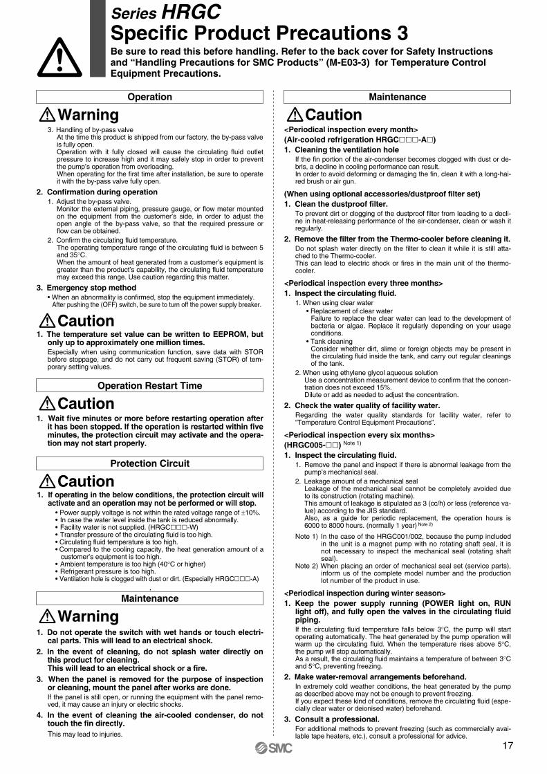
Piping
Caution
Electrical Wiring
Warning
Caution
Facility Water Supply
Warning
Caution
Mounting / Installation
Warning1. Do not place heavy objects on top of this product or step on it.
The external panel can be deformed and danger can result.
2. Do not directly touch the edge of the external panel when removing and installing it. It may cause injury. Be sure to wear protective gloves.
3. Lower the adjusters and do not move. Be sure to lower all four adjusters to the level of the floor.
M3M4M5M6
0.63 1.5 3 5.2
Connection thread
Applicable tightening torque N m
M8M10M12
12.524.542
Connection thread
Applicable tightening torque N m
Fixing Threads Tightening Torque
Piping
Caution
Operation
Warning
1. Install on a rigid floor which can withstand this product’s weight.
2. Secure with bolts, anchor bolts, etc.Fasteners such as bolts or anchor bolts should be tighten with the re-commended torque shown below.
(When using optional accessories/dustproof filter set)1. Use the attached surface fastener (with adhesive tape) to
affix the dustproof filter to the panel of the Thermo-cooler.2. Mounting the filter will create a certain amount of resistan-
ce to ventilation that will reduce the volume of airflow.For this reason, be sure to keep the ambient temperature at 40°C or less.
3. Depending on the installation height of the Thermo-cooler and/or the cooled substrates, the circulating fluid may overflow from the tank lid or overflow outlet.In particular, avoid overflow from the lid of the built-in tank by installing with a height difference of 10 m or less.Be sure to pipe the overflow outlet to a wastewater collection pit, etc.
1. Regarding the circulating fluid pipings, consider carefully the suitability for shutoff pressure, temperature and circu-lating fluid. If the operating performance is not sufficient, the pipings may burst du-ring operation.
2. For the circulating fluid pipings, use clean pipings which have no dust, piping debris or other foreign objects inside the pipings, and blow with air prior to undertaking any pi-ping works. If piping debris or other foreign objects remain inside the circulating fluid circuit, it can result in blockage, insufficient cooling or damage to the pump impeller.
3. Select the piping port size which can exceed the rated flow.For the rated flow, refer to the pump capacity table.
4. When tightening at the circulating fluid inlets and outlets, tank drain port or overflow outlet of this product, use a pi-pe wrench to clamp the connection ports.
5. For the circulating fluid piping connection, install a drain pan and wastewater collection pit just in case the circula-ting fluid leaks.
6. While cleaning the inside of the tank, attach a valve to the tank drain outlet to drain the circulating fluid (clear water).
7. This product series consists of circulating fluid temperatu-re controllers with built-in tanks. Do not install equipment on your system side such as pumps that for-cibly return the circulating fluid to the unit. Also, if you attach an external tank that is open to the air, it may become impossible to circulate the cir-culating fluid. Proceed with caution.
(Water-cooled refrigeration HRGC-W)1. When tightening the facility water inlets and outlets of this
product, use a pipe wrench to clamp the connection ports.2. Install by-pass piping.
This product has a built-in water control valve, so when the refrigeration circuit is stopped, facility water does not flow out in order to save energy.For this reason, by-pass piping is necessary for conducting maintenan-ce of your facility water equipment, so be sure to install it.
1. Never change the set value of the safety instrument. If the set value is changed, it will likely cause a breakdown or cause the product to catch on fire.
2. Before wiring, be sure to cut the power supply. Never perform any job while the product is energised.
3. Secure the cable so that its force, etc. is not applied to the terminal connector parts. When the connection or attachment is incomplete, it will likely lead to an electrical shock, a fire, etc.
4. Grounding should never be connected to a water line, gas line or lightning rod.
5. Multiple wiring is dangerous because it will lead to heat ge-neration or cause a fire.
1. Power supply, signal cable and connecting terminal should be prepared by the customer.
(When using the HRGC--C with optional communications function)1. Communication cables and adapters should be prepared
by the customer.Prepare parts that conform to the connector specifications of your host computer.
2. Pay attention to the polarity when connecting communication cables.
(Water-cooled refrigeration HRGC-W)1. Before startup, be sure to open the valve of your facility
water equipment.Prepare before startup, so that facility water can flow when the fitted wa-ter control valve (facility water control valve) opens during operation.
2. Supply pressure should be 0.5 MPa or less. When the supply pressure is high, it will cause water leakage.
3. Be sure to prepare your utilities so that the pressure of the Thermo-cooler facility water outlet is at 0 MPa (atmosphe-ric pressure) or more.If the facility water outlet pressure becomes negative, the internal facility water piping may collapse, and proper flow control of facility water will be impossible.
1. Confirmation before operation 1. The fluid level of a tank should be within the specified range of
“HIGH” and “LOW”.When exceeding the specified level, the circulating fluid will overflow.
2. Remove the air.Conduct a trial operation, looking at the fluid level.Since the fluid level will go down when the air is removed from a cus -tomer’s piping system, supply water once again when the fluid level is reduced. When there is no reduction in the fluid level, the job of removing the air is completed.
Series HRGCSpecific Product Precautions 2Be sure to read this before handling. Refer to the back cover for Safety Instructions and “Handling Precautions for SMC Products” (M-E03-3) for Temperature Control Equipment Precautions.
Operation
WarningMaintenance
Caution
Caution
Operation Restart Time
Caution
Protection Circuit
Caution
Maintenance
Warning
3. Handling of by-pass valveAt the time this product is shipped from our factory, the by-pass valve is fully open.Operation with it fully closed will cause the circulating fluid outlet pressure to increase high and it may safely stop in order to prevent the pump’s operation from overloading.When operating for the first time after installation, be sure to operate it with the by-pass valve fully open.
2. Confirmation during operation 1. Adjust the by-pass valve.
Monitor the external piping, pressure gauge, or flow meter mounted on the equipment from the customer’s side, in order to adjust the open angle of the by-pass valve, so that the required pressure or flow can be obtained.
2. Confirm the circulating fluid temperature.The operating temperature range of the circulating fluid is between 5 and 35°C. When the amount of heat generated from a customer’s equipment is greater than the product’s capability, the circulating fluid temperature may exceed this range. Use caution regarding this matter.
3. Emergency stop method • When an abnormality is confirmed, stop the equipment immediately.
After pushing the (OFF) switch, be sure to turn off the power supply breaker.
1. The temperature set value can be written to EEPROM, but only up to approximately one million times.Especially when using communication function, save data with STOR before stoppage, and do not carry out frequent saving (STOR) of tem-porary setting values.
1. Wait five minutes or more before restarting operation after it has been stopped. If the operation is restarted within five minutes, the protection circuit may activate and the opera-tion may not start properly.
1. If operating in the below conditions, the protection circuit will activate and an operation may not be performed or will stop.
• Power supply voltage is not within the rated voltage range of ±10%. • In case the water level inside the tank is reduced abnormally.• Facility water is not supplied. (HRGC-W)• Transfer pressure of the circulating fluid is too high. • Circulating fluid temperature is too high.• Compared to the cooling capacity, the heat generation amount of a
customer’s equipment is too high.• Ambient temperature is too high (40°C or higher)• Refrigerant pressure is too high.• Ventilation hole is clogged with dust or dirt. (Especially HRGC-A)
1. Do not operate the switch with wet hands or touch electri-cal parts. This will lead to an electrical shock.
2. In the event of cleaning, do not splash water directly on this product for cleaning.This will lead to an electrical shock or a fire.
3. When the panel is removed for the purpose of inspection or cleaning, mount the panel after works are done.If the panel is still open, or running the equipment with the panel remo-ved, it may cause an injury or electric shocks.
4. In the event of cleaning the air-cooled condenser, do not touch the fin directly.This may lead to injuries.
<Periodical inspection every month>(Air-cooled refrigeration HRGC-A)1. Cleaning the ventilation hole
If the fin portion of the air-condenser becomes clogged with dust or de-bris, a decline in cooling performance can result.In order to avoid deforming or damaging the fin, clean it with a long-hai-red brush or air gun.
(When using optional accessories/dustproof filter set)1. Clean the dustproof filter.
To prevent dirt or clogging of the dustproof filter from leading to a decli-ne in heat-releasing performance of the air-condenser, clean or wash it regularly.
2. Remove the filter from the Thermo-cooler before cleaning it.Do not splash water directly on the filter to clean it while it is still atta-ched to the Thermo-cooler.This can lead to electric shock or fires in the main unit of the thermo-cooler.
<Periodical inspection every three months>1. Inspect the circulating fluid.
1. When using clear water • Replacement of clear water
Failure to replace the clear water can lead to the development of bacteria or algae. Replace it regularly depending on your usage conditions.
• Tank cleaningConsider whether dirt, slime or foreign objects may be present in the circulating fluid inside the tank, and carry out regular cleanings of the tank.
2. When using ethylene glycol aqueous solutionUse a concentration measurement device to confirm that the concen-tration does not exceed 15%.Dilute or add as needed to adjust the concentration.
2. Check the water quality of facility water. Regarding the water quality standards for facility water, refer to “Temperature Control Equipment Precautions”.
<Periodical inspection every six months>(HRGC005-) Note 1)
1. Inspect the circulating fluid.1. Remove the panel and inspect if there is abnormal leakage from the
pump’s mechanical seal.2. Leakage amount of a mechanical seal
Leakage of the mechanical seal cannot be completely avoided due to its construction (rotating machine).This amount of leakage is stipulated as 3 (cc/h) or less (reference va-lue) according to the JIS standard.Also, as a guide for periodic replacement, the operation hours is 6000 to 8000 hours. (normally 1 year) Note 2)
Note 1) In the case of the HRGC001/002, because the pump included in the unit is a magnet pump with no rotating shaft seal, it is not necessary to inspect the mechanical seal (rotating shaft seal).
Note 2) When placing an order of mechanical seal set (service parts), inform us of the complete model number and the production lot number of the product in use.
<Periodical inspection during winter season>1. Keep the power supply running (POWER light on, RUN
light off), and fully open the valves in the circulating fluid piping.If the circulating fluid temperature falls below 3°C, the pump will start operating automatically. The heat generated by the pump operation will warm up the circulating fluid. When the temperature rises above 5°C, the pump will stop automatically.As a result, the circulating fluid maintains a temperature of between 3°C and 5°C, preventing freezing.
2. Make water-removal arrangements beforehand.In extremely cold weather conditions, the heat generated by the pump as described above may not be enough to prevent freezing.If you expect these kind of conditions, remove the circulating fluid (espe-cially clear water or deionised water) beforehand.
3. Consult a professional.For additional methods to prevent freezing (such as commercially avai-lable tape heaters, etc.), consult a professional for advice.
Series HRGCSpecific Product Precautions 3Be sure to read this before handling. Refer to the back cover for Safety Instructions and “Handling Precautions for SMC Products” (M-E03-3) for Temperature Control Equipment Precautions.
17

Safety Instructions Be sure to read “Handling Precautions for SMC Products” (M-E03-3) before using.
Lithuania +370 5 2308118 www.smclt.lt [email protected] +31 (0)205318888 www.smcpneumatics.nl [email protected] +47 67129020 www.smc-norge.no [email protected] +48 222119600 www.smc.pl [email protected] +351 226166570 www.smc.eu [email protected] +40 213205111 www.smcromania.ro [email protected] +7 8127185445 www.smc-pneumatik.ru [email protected] +421 413213212 www.smc.sk [email protected] +386 73885412 www.smc.si [email protected] +34 945184100 www.smc.eu [email protected] +46 (0)86031200 www.smc.nu [email protected] +41 (0)523963131 www.smc.ch [email protected] +90 (0)2124440762 www.entek.com.tr [email protected] UK +44 (0)845 121 5122 www.smcpneumatics.co.uk [email protected]
Specifications are subject to change without prior notice and any obligation on the part of the manufacturer.SMC CORPORATION Akihabara UDX 15F, 4-14-1, Sotokanda, Chiyoda-ku, Tokyo 101-0021, JAPAN Phone: 03-5207-8249 FAX: 03-5298-5362
1st printing OP printing OP 00 Printed in Spain
Austria +43 2262622800 www.smc.at [email protected] +32 (0)33551464 www.smcpneumatics.be [email protected] +359 29744492 www.smc.bg [email protected] +385 13776674 www.smc.hr [email protected] Republic +420 541424611 www.smc.cz [email protected] +45 70252900 www.smcdk.com [email protected] Estonia +372 6510370 www.smcpneumatics.ee [email protected] +358 207513513 www.smc.fi [email protected] +33 (0)164761000 www.smc-france.fr [email protected] +49 (0)61034020 www.smc-pneumatik.de [email protected] +30 210 2717265 www.smchellas.gr [email protected] +36 23511390 www.smc.hu [email protected] +353 (0)14039000 www.smcpneumatics.ie [email protected] +39 (0)292711 www.smcitalia.it [email protected] +371 67817700 www.smclv.lv [email protected]
SMC Corporation (Europe)
1. The compatibility of the product is the responsibility of the person who designs the equipment or decides its specifications.Since the product specified here is used under various operating conditions, its compatibility with specific equipment must be decided by the person who designs the equipment or decides its specifications based on necessary analysis and test results. The expected performance and safety assurance of the equipment will be the responsibility of the person who has determined its compatibility with the product. This person should also continuously review all specifications of the product referring to its latest catalogue information, with a view to giving due consideration to any possibility of equipment failure when configuring the equipment.
2. Only personnel with appropriate training should operate machinery and equipment.The product specified here may become unsafe if handled incorrectly. The assembly, operation and maintenance of machines or equipment including our products must be performed by an operator who is appropriately trained and experienced.
3. Do not service or attempt to remove product and machinery/equipment until safety is confirmed.1. The inspection and maintenance of machinery/equipment should only be
performed after measures to prevent falling or runaway of the driven objects have been confirmed.
2. When the product is to be removed, confirm that the safety measures as mentioned above are implemented and the power from any appropriate source is cut, and read and understand the specific product precautions of all relevant products carefully.
3. Before machinery/equipment is restarted, take measures to prevent unexpected operation and malfunction.
4. Contact SMC beforehand and take special consideration of safety measures if the product is to be used in any of the following conditions. 1. Conditions and environments outside of the given specifications, or use
outdoors or in a place exposed to direct sunlight.2. Installation on equipment in conjunction with atomic energy, railways, air
navigation, space, shipping, vehicles, military, medical treatment, combustion and recreation, or equipment in contact with food and beverages, emergency stop circuits, clutch and brake circuits in press applications, safety equipment or other applications unsuitable for the standard specifications described in the product catalogue.
3. An application which could have negative effects on people, property, or animals requiring special safety analysis.
4. Use in an interlock circuit, which requires the provision of double interlock for possible failure by using a mechanical protective function, and periodical checks to confirm proper operation.
Warning
Limited warranty and Disclaimer/Compliance Requirements The product used is subject to the following “Limited warranty and Disclaimer” and “Compliance Requirements”.Read and accept them before using the product.
1. The product is provided for use in manufacturing industries.The product herein described is basically provided for peaceful use in manufacturing industries. If considering using the product in other industries, consult SMC beforehand and exchange specifications or a contract if necessary. If anything is unclear, contact your nearest sales branch.
Caution
Limited warranty and Disclaimer1. The warranty period of the product is 1 year in service or 1.5 years after
the product is delivered.∗2)
Also, the product may have specified durability, running distance or replacement parts. Please consult your nearest sales branch.
2. For any failure or damage reported within the warranty period which is clearly our responsibility, a replacement product or necessary parts will be provided. This limited warranty applies only to our product independently, and not to any ot-her damage incurred due to the failure of the product.
3. Prior to using SMC products, please read and understand the warranty terms and disclaimers noted in the specified catalogue for the particular products.
∗2) Vacuum pads are excluded from this 1 year warranty.A vacuum pad is a consumable part, so it is warranted for a year after it is delivered. Also, even within the warranty period, the wear of a product due to the use of the vacuum pad or failure due to the deterioration of rubber material are not covered by the limited warranty.
Compliance Requirements1. The use of SMC products with production equipment for the manufacture of
weapons of mass destruction (WMD) or any other weapon is strictly prohibited.
2. The exports of SMC products or technology from one country to another are governed by the relevant security laws and regulations of the countries involved in the transaction. Prior to the shipment of a SMC product to another country, assure that all local rules governing that export are known and followed.
These safety instructions are intended to prevent hazardous situations and/or equipment damage. These instructions indicate the level of potential hazard with the labels of “Caution,” “Warning” or “Danger.” They are all important notes for safety and must be followed in addition to International Standards (ISO/IEC)∗1), and other safety regulations.
∗1) ISO 4414: Pneumatic fluid power – General rules relating to systems.ISO 4413: Hydraulic fluid power – General rules relating to systems.IEC 60204-1: Safety of machinery – Electrical equipment of machines.
(Part 1: General requirements)ISO 10218-1: Manipulating industrial robots - Safety.etc.
Caution indicates a hazard with a low level of risk which, if not avoided, could result in minor or moderate injury.
Warning indicates a hazard with a medium level of risk which, if not avoided, could result in death or serious injury.
Caution:
Warning:
Danger :Danger indicates a hazard with a high level of risk which, if not avoided, will result in death or serious injury.
Safety Instructions