Embed Size (px)
Citation preview

Cirrus Powerchair Owners Handbook Page 1 of 24 Doc Code: PCC_IFU (02/15)
CIRRUS POWERCHAIR OWNER’S HANDBOOK
Cirrus Powerchair Owners Handbook Page 2 of 24 Doc Code: PCC_IFU (02/15)
CONTENTS
1. Contents
2. Introduction
3. Personal Safety
4. Parts Description
5. Control Functions Operation
6. Adjustments for Comfort
7. Transportation, Assembly and
Disassembly
8. Battery Charging
9. Care and Maintenance
10. Service Record
11. Warranty
12. Troubleshooting
13. Specification
INTRODUCTION
The Cirrus powerchair has been designed for a single occupant user mass of up to
135kg. The design of the powerchair assumes that the user has limited mobility
but has the physical, visual and cognitive ability to operate the powerchair safely.
The powerchair is suitable for everyday indoor and limited outdoor use. It is
suitable for use on outdoor pavements, patios, paths, gravel and similar
environment. It is not suitable for fields, ditches or similar. If the powerchair is
used in heavy rain or in the wet for prolonged periods, the user and powerchair
should be protected with a rain cape.
All Enigma powerchair are manufactured to the highest standards and are CE
compliant. The Cirrus powerchair is a robust and visually appealing product
whilst being a cost-effective solution to some mobility problems.
It is essential that you read this manual before using your Cirrus powerchair. If
you have any questions about the manual or the powerchair in general, please
contact the outlet from who you purchased the powerchair.
Cirrus Powerchair Owners Handbook Page 3 of 24 Doc Code: PCC_IFU (02/15)
PERSONAL SAFETY GENERAL OPERATING SAFETY PROCEDURES
Make sure that the powerchair is switched off before entering or exiting the
powerchair.
For your health and comfort, make sure that you adopt a comfortable posture
and that you can operate the controller unit with ease.
Make sure that you are visible when using the chair at night or in poorly lit
conditions.
Be carefuls when driving your powerchair as evening falls. It has not been
deisgned for use at night or for use in severe weather conditions such as rain
and snow.
Ensure that any modification made to the powerchair are approved by Drive
Medical. Unauthroised modifications may reduce the performance of the
powerchair, invalidate the warranty, or result in injury or damage.
There is a risk for trapping with powerchairs. Ensure all clothing is kept away
from moving parts (e.g. wheels and motors).
Drive on the pavement and pedestrian areas only. The powerchair can be
used to cross the road on a single carriageway or when there is no pavement
present.
Do not take the powerchair on escalators.
Do not use a mobile phone or other wireless communication devices whilst
driving as they could interefere with the powerchair controls. Always switch
off the powerchair before using a mobile phone.
Do not use the powerchair as a seat in a motor vehicle. The powerchair has
not been tested for this purpose.
EMERGENCY BRAKING
The powerchair has automatic electromagnetic brakes which will act as
parking brakes and are use to slow down the powerchair during normal use.
The powerchair is brought to a stop gently by releasing the joystick.
However, you can apply the emergency brakes by switching off the
powerchair. This is an abrupt method of braking and should only be used as a
last resort in an emergency.
There is a manual parking brake located beside each drive wheel. These
brakes should only be used when the powerchair is stationary and when in
freewheel mode.
Cirrus Powerchair Owners Handbook Page 4 of 24 Doc Code: PCC_IFU (02/15)
PERSONAL SAFETY (CONTINUED)
TURNING AND USING ON A GRADIENT GUIDELINES
Avoid sharp turns at high speed as this could result in the powerchair
tipping over. This is especially relevant when turning on a gradient.
The powerchair has been designed for use on gradients up to 1 in 6 (10º).
However this can vary due to other factors such as the surface of the
gradient or the attributes of the user. If you are in any doubt about going up
or down a gradient please find an alternative route.
Please slow down when driving on gradients.
EMERGENCY FREEWHEEL
Warning: The powerchair has a freewheel option device fitted on the top of
each motor. Always re-engage the emergency freewheel device after use.
Failure to do so may result in injury.
OBSTACLES AND KERBS
Be careful when driving to avoid obstacles which could come in to contact
with the powerchair, in particular the front castors. If you cannot avoid an
obstacle, then negotiate it slowly with care.
Repeated heavy impacts could reduce the performance of the powerchair
and may result in damage or injury.
ELECTROMAGNETIC INTERFERENCE (EMI) FROM RADIO WAVES
Powered wheelchairs may be susceptible to electromagnetic interference (EMI)
which is interfering electromagnetic energy (EM) emitted from sources such as
radio stations, TV stations, amateur radio (HAM) transmitters, two-way radios
and mobile phones. The interference (from radio wave sources) can cause the
powered wheelchair to release its brakes, move by itself, or move in an
unintended direction. It can also permanently damage the powered wheelchair’s
control system.
Cirrus Powerchair Owners Handbook Page 5 of 24 Doc Code: PCC_IFU (02/15)
PERSONAL SAFETY (CONTINUED) The intensity of the interfering EM energy can be measured in volts per metre
(V/m). Each powered wheelchair can resist EMI up to a certain intensity. This is
called its “immunity level”. The higher the immunity level, the greater the
protection. At this time, current technology is capable of achieving at least a 20
V/m immunity level, which would provide useful protection from the more
common sources of radiated EMI. This powered wheelchair model as shipped,
with no further modification, has an immunity level of 20 V/m without any
accessories.
There are a number of sources of relatively intensive electromagnetic fields in
the everyday environment. Some of these sources are obvious and easy to avoid.
Others are not apparent and exposure is unavoidable. However, we believe that
by following the warnings listed below, your risk to EMI will be minimized.
The source of radiated EMI can be broadly classified into three types:
1. Hand-held portable transceivers (transmitter-receivers with the antenna
mounted directly on the transmitting unit). Examples include citizens
band (CB) radios, walkie talkies, security, fire and police transceivers,
mobile phones and other personal communication devices.
2. Medium range mobile transceivers, such as those used in police cars, fire
engines, ambulances and taxis. These usually have the antenna mounted
on the outside of the vehicle.
3. Long-range transmitters and transceivers, such as commercial broadcast
transmitters (radio and TV broadcast antenna towers) and amateur (HAM)
radios.
Because EM energy rapidly becomes more intense as one moves closer to the
transmitting antenna (source), the EM fields from hand-held radio wave sources
(transceivers) are of special concern. It is possible to unintentionally bring high
levels of EM energy very close to the control system of the powerchair while
using these devices. This can affect powered wheelchair movement and braking.
Therefore, the warnings listed overleaf are recommended to prevent possible
interference with the control system of the powered wheelchair. Following the
warnings listed below should reduce the chance of unintended brake release or
movement as a result of EMI:
Cirrus Powerchair Owners Handbook Page 6 of 24 Doc Code: PCC_IFU (02/15)
PERSONAL SAFETY (CONTINUED)
1. Do not operate hand-held transceivers-receivers, such as citizens band
(CB) radios, or turn ON personal communication devices, such as mobile
phones, while the Powerchair is turned ON.
2. Be aware of nearby transmitters, such as radio or TV stations, and try to
avoid coming close to them.
3. If unintended movement or brake release occurs, turn the Powerchair OFF
as soon as it is safe to do so.
4. Be aware that adding accessories or components, or modifying the
Powerchair, may make it more susceptible to EMI (there is no easy way to
evaluate their effect on the overall immunity of the Powerchair).
5. Report all incidents of unintended movement or brake release to the
Powerchair manufacturer and note whether there is an EMI source nearby
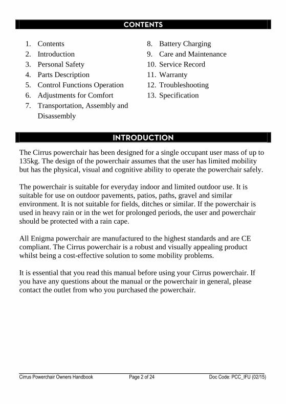
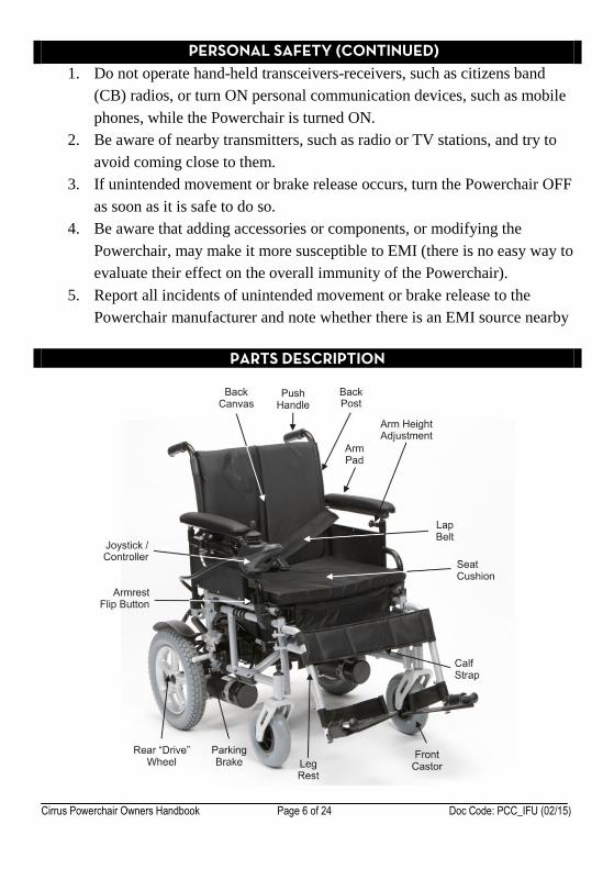
PARTS DESCRIPTION
Cirrus Powerchair Owners Handbook Page 7 of 24 Doc Code: PCC_IFU (02/15)
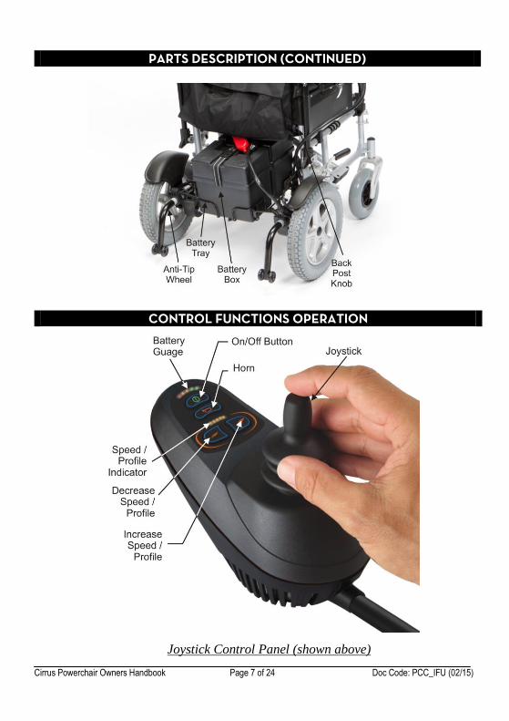
PARTS DESCRIPTION (CONTINUED)
CONTROL FUNCTIONS OPERATION
Joystick Control Panel (shown above)
Cirrus Powerchair Owners Handbook Page 8 of 24 Doc Code: PCC_IFU (02/15)
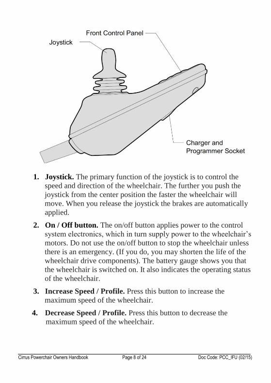
1. Joystick. The primary function of the joystick is to control the
speed and direction of the wheelchair. The further you push the
joystick from the center position the faster the wheelchair will
move. When you release the joystick the brakes are automatically
applied.
2. On / Off button. The on/off button applies power to the control
system electronics, which in turn supply power to the wheelchair’s
motors. Do not use the on/off button to stop the wheelchair unless
there is an emergency. (If you do, you may shorten the life of the
wheelchair drive components). The battery gauge shows you that
the wheelchair is switched on. It also indicates the operating status
of the wheelchair.
3. Increase Speed / Profile. Press this button to increase the
maximum speed of the wheelchair.
4. Decrease Speed / Profile. Press this button to decrease the
maximum speed of the wheelchair.
Cirrus Powerchair Owners Handbook Page 9 of 24 Doc Code: PCC_IFU (02/15)
5. Speed / Profile Indicator. This shows the maximum speed of the
wheelchair. The more LEDs are lit, the faster the maximum speed.
The wheelchair can be configured to use drive profiles. However,
this is not included by default. For more information about drive
profiles, contact your dealer. If the speed indicator ripples, this
means the wheelchair is locked. By default the locking function is
disabled.
To unlock / lock the wheelchair:
Switch the wheelchair on
Hold down the on/off button for 1 second (lock only)
Deflect the joystick forwards until the control system bleeps
Deflect the joystick backwards until the control system bleeps
Release the joystick. There will be a long bleep and the
wheelchair will be unlocked / locked.
6. Horn. Press this button to sound the horn. The horn will stop when
you release the button.
7. Battery Gauge. This shows the battery power level of the
wheelchair.
The more LEDs that are lit, the more power is left in the battery.
The LEDs will be lit constantly when the wheelchair is operating
normally.
If the LEDs on the battery gauge are stepping up (i.e. the number
of LEDs lit quickly increases then resets to 1), the battery charger
is connected and the wheelchair drive inhibited.
If the battery gauge is flashing slowly then the wheelchair is
operating normally, but the batteries need recharging as soon as
possible.
If the battery gauge LEDs are flashing rapidly this indicates a fault
with the wheelchair. If you have a problem with your wheelchair
consult the table overleaf. If the problem persists after you have
followed the advice overleaf then restarted the wheelchair, contact
Cirrus Powerchair Owners Handbook Page 10 of 24 Doc Code: PCC_IFU (02/15)
your dealer.
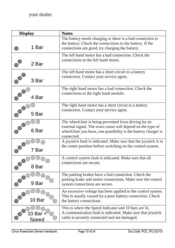
Display Notes
1 Bar
The battery needs charging or there is a bad connection to
the battery. Check the connections to the battery. If the
connections are good, try charging the battery.
2 Bar
The left hand motor has a bad connection. Check the
connections to the left hand motor.
3 Bar
The left hand motor has a short circuit to a battery
connection. Contact your service agent.
4 Bar
The right hand motor has a bad connection. Check the
connections to the right hand module.
5 Bar
The right hand motor has a short circuit to a battery
connection. Contact your service agent.
6 Bar
The wheelchair is being prevented from driving by an
external signal. The exact cause will depend on the type of
wheelchair you have, one possibility is the battery charger is
connected.
7 Bar
A joystick fault is indicated. Make sure that the joystick is in
the centre position before switching on the control system.
8 Bar
A control system fault is indicated. Make sure that all
connections are secure.
9 Bar
The parking brakes have a bad connection. Check the
parking brake and motor connections. Make sure the control
system connections are secure.
10 Bar
An excessive voltage has been applied to the control system.
This is usually caused by a poor battery connection. Check
the battery connections.
10 Bar +
Speed
This is where the Speed Indicator and 10 bars are lit.
A communication fault is indicated. Make sure that joystick
cable is securely connected and not damaged.
Cirrus Powerchair Owners Handbook Page 11 of 24 Doc Code: PCC_IFU (02/15)
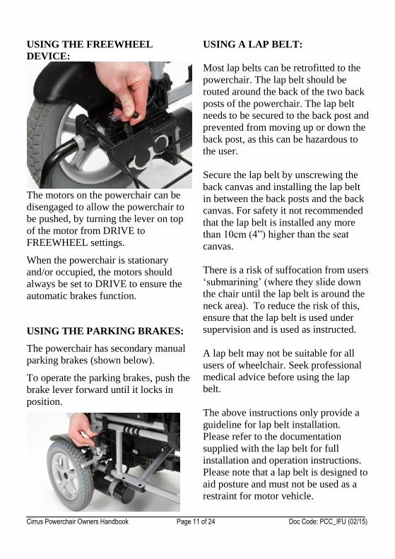
USING THE FREEWHEEL
DEVICE:
The motors on the powerchair can be
disengaged to allow the powerchair to
be pushed, by turning the lever on top
of the motor from DRIVE to
FREEWHEEL settings.
When the powerchair is stationary
and/or occupied, the motors should
always be set to DRIVE to ensure the
automatic brakes function.
USING THE PARKING BRAKES:
The powerchair has secondary manual
parking brakes (shown below).
To operate the parking brakes, push the
brake lever forward until it locks in
position.
USING A LAP BELT:
Most lap belts can be retrofitted to the
powerchair. The lap belt should be
routed around the back of the two back
posts of the powerchair. The lap belt
needs to be secured to the back post and
prevented from moving up or down the
back post, as this can be hazardous to
the user.
Secure the lap belt by unscrewing the
back canvas and installing the lap belt
in between the back posts and the back
canvas. For safety it not recommended
that the lap belt is installed any more
than 10cm (4”) higher than the seat
canvas.
There is a risk of suffocation from users
‘submarining’ (where they slide down
the chair until the lap belt is around the
neck area). To reduce the risk of this,
ensure that the lap belt is used under
supervision and is used as instructed.
A lap belt may not be suitable for all
users of wheelchair. Seek professional
medical advice before using the lap
belt.
The above instructions only provide a
guideline for lap belt installation.
Please refer to the documentation
supplied with the lap belt for full
installation and operation instructions.
Please note that a lap belt is designed to
aid posture and must not be used as a
restraint for motor vehicle.
Cirrus Powerchair Owners Handbook Page 12 of 24 Doc Code: PCC_IFU (02/15)
ADJUSTMENTS FOR COMFORT
To adjust the arms:
Pull back the armrest height
adjustment lever whilst lifting up the
arm pad. Release the lever and pull
up the arm pad until it locks. Repeat
until the required height is reached.
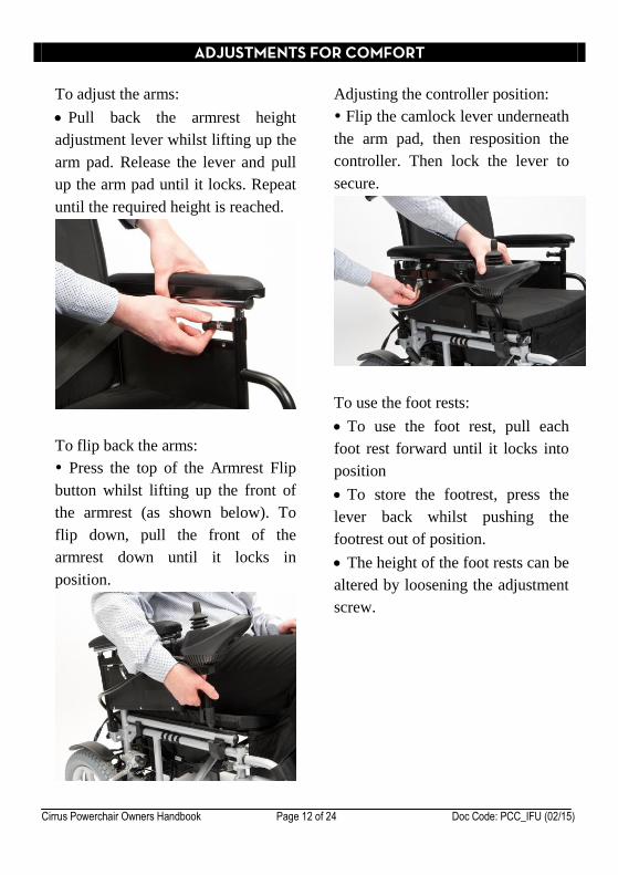
To flip back the arms:
Press the top of the Armrest Flip
button whilst lifting up the front of
the armrest (as shown below). To
flip down, pull the front of the
armrest down until it locks in
position.
Adjusting the controller position:
Flip the camlock lever underneath
the arm pad, then resposition the
controller. Then lock the lever to
secure.
To use the foot rests:
To use the foot rest, pull each
foot rest forward until it locks into
position
To store the footrest, press the
lever back whilst pushing the
footrest out of position.
The height of the foot rests can be
altered by loosening the adjustment
screw.
Cirrus Powerchair Owners Handbook Page 13 of 24 Doc Code: PCC_IFU (02/15)
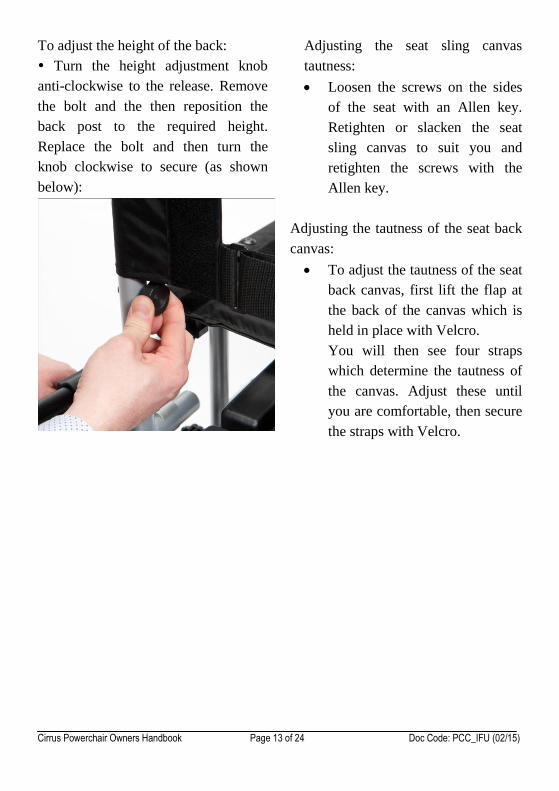
To adjust the height of the back:
Turn the height adjustment knob
anti-clockwise to the release. Remove
the bolt and the then reposition the
back post to the required height.
Replace the bolt and then turn the
knob clockwise to secure (as shown
below):
Adjusting the seat sling canvas
tautness:
Loosen the screws on the sides
of the seat with an Allen key.
Retighten or slacken the seat
sling canvas to suit you and
retighten the screws with the
Allen key.
Adjusting the tautness of the seat back
canvas:
To adjust the tautness of the seat
back canvas, first lift the flap at
the back of the canvas which is
held in place with Velcro.
You will then see four straps
which determine the tautness of
the canvas. Adjust these until
you are comfortable, then secure
the straps with Velcro.
Cirrus Powerchair Owners Handbook Page 14 of 24 Doc Code: PCC_IFU (02/15)
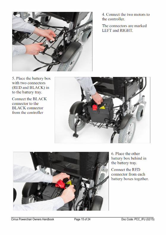
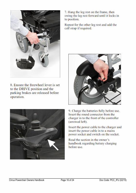
ASSEMBLY, DISASSEMBLY AND TRANSPORTATION
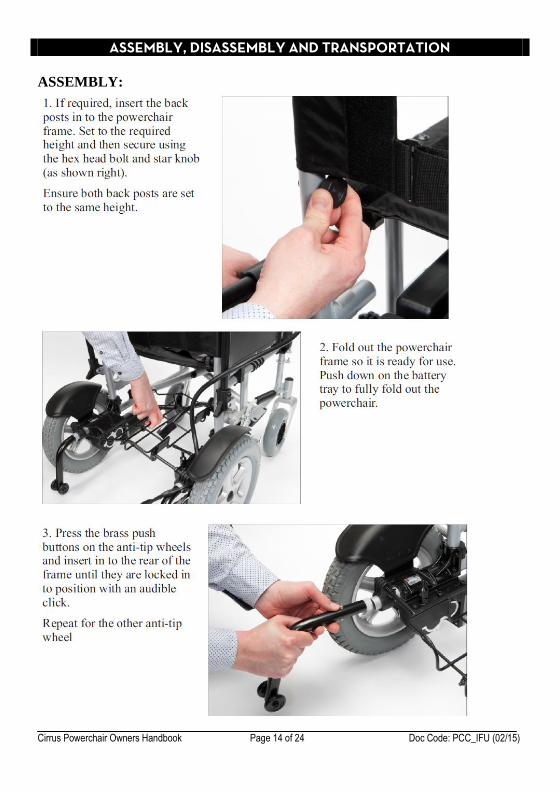
ASSEMBLY:
Cirrus Powerchair Owners Handbook Page 15 of 24 Doc Code: PCC_IFU (02/15)
Cirrus Powerchair Owners Handbook Page 16 of 24 Doc Code: PCC_IFU (02/15)
Cirrus Powerchair Owners Handbook Page 17 of 24 Doc Code: PCC_IFU (02/15)
DISASSEMBLY:
The disassembly procedure is the assembly procedure in reverse. Please study the
assembly procedure before attempting this procedure. To disassemble:
1. If installed, remove the calf strap. Then press the button on the side of the
leg rest to swing away. Once swung away, the leg rests can be lifted up to
remove.
2. Disconnect the RED and BLACK connectors on the battery boxes. Lift up
the battery boxes to remove.
3. Remove the seat cushion and back cushion.
4. Lift up the centre of the battery box and then the centre of the seat sling to
fold up the frame.
5. If required, remove the back posts and anti-tip wheels.
TRANSPORTATION:
If required, fold up and disassemble the powerchair for transportation. The
powerchair should always be securely restrained during transportation, and
preferably folded and in a car boot or luggage section. The powerchair is not
suitable for use as a seat in a motor vehicle, so the wheelchair occupant should
always exit the chair and transfer the vehicle’s seat before travelling.
Cirrus Powerchair Owners Handbook Page 18 of 24 Doc Code: PCC_IFU (02/15)
BATTERY CHARGING
CHARGING THE BATTERIES
The batteries require charging on a regular basis to minimise the risk of you
being stranded due to the batteries being flat. Ideally, you should charge the
batteries whenever the powerchair is not in use to make sure that there is always
the maximum available range for the powerchair.
The information gauge supplied on the joystick displays the amount of charge
left in the batteries. This gauge however should only be used as an approximate
guide. The battery is at full charge when all the lights are lit and the number of
lights lit will reduce once power is used.
When the leftmost red LED starts flashing, recharge the powerchair batteries as
soon as possible, as this is a warning that the powerchair is running low on
power.
To charge the batteries:
Turn off the powerchair
Insert the round plug from the charger into the joystick and switch the
charger on. The charging socket is located at the front of the joystick unit.
Charge the batteries for at least 12 hours for maximum capacity
BATTERY CHARGING (CONTINUED)
CHARGER OPERATION
Both the charger’s LEDs will illuminate when charging.
The red LED is lit whenever the charger is switched on.
The other LED will illuminate when connected to the powerchair.
The other LED is lit amber when bulk charging and then green when
trickle charging (after bulk charging has finished).
Warning: Please note the fan inside the charger will be activated accordingly
when you switch on the charger. If you find the fan does not work
when the amber LED is lit, DO NOT use the charger. To do so may
result in the charger overheating and risk of fire.
Cirrus Powerchair Owners Handbook Page 19 of 24 Doc Code: PCC_IFU (02/15)
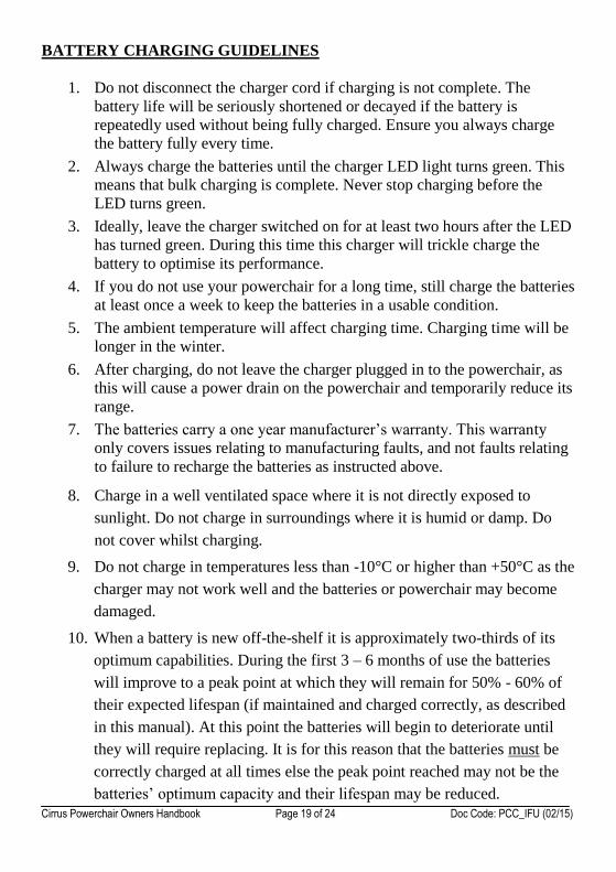
BATTERY CHARGING GUIDELINES
1. Do not disconnect the charger cord if charging is not complete. The
battery life will be seriously shortened or decayed if the battery is
repeatedly used without being fully charged. Ensure you always charge
the battery fully every time.
2. Always charge the batteries until the charger LED light turns green. This
means that bulk charging is complete. Never stop charging before the
LED turns green.
3. Ideally, leave the charger switched on for at least two hours after the LED
has turned green. During this time this charger will trickle charge the
battery to optimise its performance.
4. If you do not use your powerchair for a long time, still charge the batteries
at least once a week to keep the batteries in a usable condition.
5. The ambient temperature will affect charging time. Charging time will be
longer in the winter.
6. After charging, do not leave the charger plugged in to the powerchair, as
this will cause a power drain on the powerchair and temporarily reduce its
range.
7. The batteries carry a one year manufacturer’s warranty. This warranty
only covers issues relating to manufacturing faults, and not faults relating
to failure to recharge the batteries as instructed above.
8. Charge in a well ventilated space where it is not directly exposed to
sunlight. Do not charge in surroundings where it is humid or damp. Do
not cover whilst charging.
9. Do not charge in temperatures less than -10°C or higher than +50°C as the
charger may not work well and the batteries or powerchair may become
damaged.
10. When a battery is new off-the-shelf it is approximately two-thirds of its
optimum capabilities. During the first 3 – 6 months of use the batteries
will improve to a peak point at which they will remain for 50% - 60% of
their expected lifespan (if maintained and charged correctly, as described
in this manual). At this point the batteries will begin to deteriorate until
they will require replacing. It is for this reason that the batteries must be
correctly charged at all times else the peak point reached may not be the
batteries’ optimum capacity and their lifespan may be reduced.
Cirrus Powerchair Owners Handbook Page 20 of 24 Doc Code: PCC_IFU (02/15)
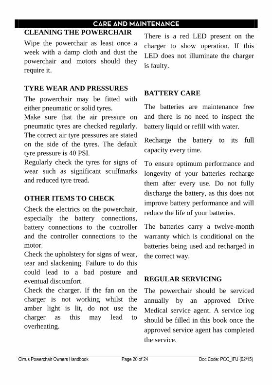
CARE AND MAINTENANCE CLEANING THE POWERCHAIR
Wipe the powerchair as least once a
week with a damp cloth and dust the
powerchair and motors should they
require it.
TYRE WEAR AND PRESSURES
The powerchair may be fitted with
either pneumatic or solid tyres.
Make sure that the air pressure on
pneumatic tyres are checked regularly.
The correct air tyre pressures are stated
on the side of the tyres. The default
tyre pressure is 40 PSI.
Regularly check the tyres for signs of
wear such as significant scuffmarks
and reduced tyre tread.
OTHER ITEMS TO CHECK
Check the electrics on the powerchair,
especially the battery connections,
battery connections to the controller
and the controller connections to the
motor.
Check the upholstery for signs of wear,
tear and slackening. Failure to do this
could lead to a bad posture and
eventual discomfort.
Check the charger. If the fan on the
charger is not working whilst the
amber light is lit, do not use the
charger as this may lead to
overheating.
There is a red LED present on the
charger to show operation. If this
LED does not illuminate the charger
is faulty.
BATTERY CARE
The batteries are maintenance free
and there is no need to inspect the
battery liquid or refill with water.
Recharge the battery to its full
capacity every time.
To ensure optimum performance and
longevity of your batteries recharge
them after every use. Do not fully
discharge the battery, as this does not
improve battery performance and will
reduce the life of your batteries.
The batteries carry a twelve-month
warranty which is conditional on the
batteries being used and recharged in
the correct way.
REGULAR SERVICING
The powerchair should be serviced
annually by an approved Drive
Medical service agent. A service log
should be filled in this book once the
approved service agent has completed
the service.
Cirrus Powerchair Owners Handbook Page 21 of 24 Doc Code: PCC_IFU (02/15)
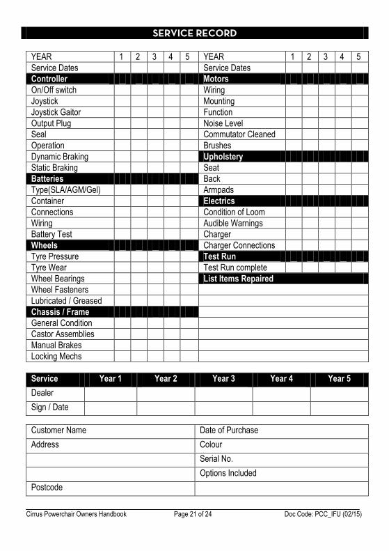
SERVICE RECORD
YEAR 1 2 3 4 5 YEAR 1 2 3 4 5
Service Dates Service Dates
Controller Motors
On/Off switch Wiring
Joystick Mounting
Joystick Gaitor Function
Output Plug Noise Level
Seal Commutator Cleaned
Operation Brushes
Dynamic Braking Upholstery
Static Braking Seat
Batteries Back
Type(SLA/AGM/Gel) Armpads
Container Electrics
Connections Condition of Loom
Wiring Audible Warnings
Battery Test Charger
Wheels Charger Connections
Tyre Pressure Test Run
Tyre Wear Test Run complete
Wheel Bearings List Items Repaired
Wheel Fasteners
Lubricated / Greased
Chassis / Frame
General Condition
Castor Assemblies
Manual Brakes
Locking Mechs
Service Year 1 Year 2 Year 3 Year 4 Year 5
Dealer
Sign / Date
Customer Name Date of Purchase
Address Colour
Serial No.
Options Included
Postcode
Cirrus Powerchair Owners Handbook Page 22 of 24 Doc Code: PCC_IFU (02/15)
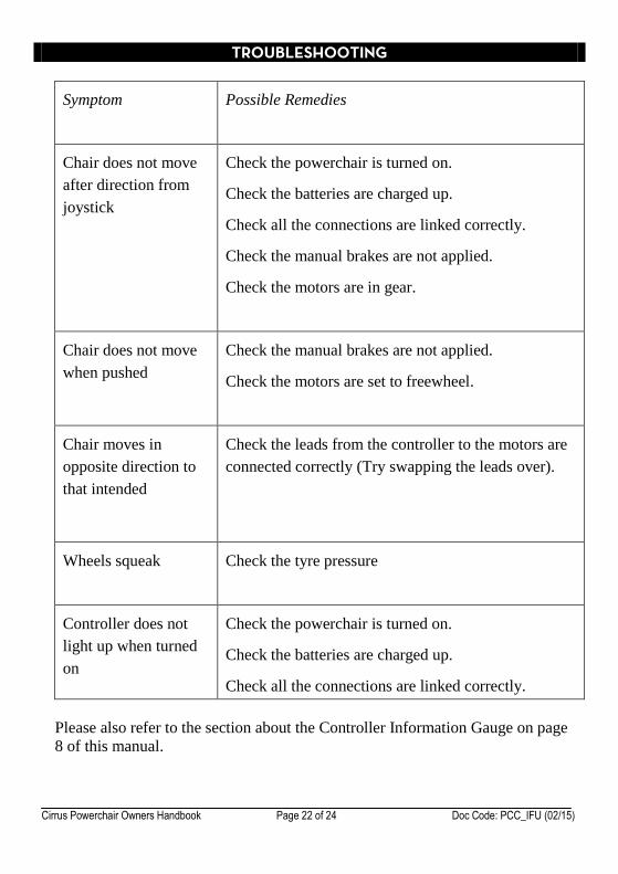
TROUBLESHOOTING
Symptom Possible Remedies
Chair does not move
after direction from
joystick
Check the powerchair is turned on.
Check the batteries are charged up.
Check all the connections are linked correctly.
Check the manual brakes are not applied.
Check the motors are in gear.
Chair does not move
when pushed
Check the manual brakes are not applied.
Check the motors are set to freewheel.
Chair moves in
opposite direction to
that intended
Check the leads from the controller to the motors are
connected correctly (Try swapping the leads over).
Wheels squeak Check the tyre pressure
Controller does not
light up when turned
on
Check the powerchair is turned on.
Check the batteries are charged up.
Check all the connections are linked correctly.
Please also refer to the section about the Controller Information Gauge on page
8 of this manual.
Cirrus Powerchair Owners Handbook Page 23 of 24 Doc Code: PCC_IFU (02/15)
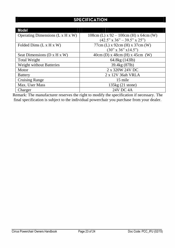
SPECIFICATION
Model
Operating Dimensions (L x H x W) 108cm (L) x 92 – 100cm (H) x 64cm (W)
(42.5” x 36” – 39.5” x 25”)
Folded Dims (L x H x W) 77cm (L) x 92cm (H) x 37cm (W)
(30” x 36” x14.5”)
Seat Dimensions (D x H x W) 40cm (D) x 48cm (H) x 45cm (W)
Total Weight 64.8kg (143lb)
Weight without Batteries 39.4kg (87lb)
Motor 2 x 320W 24V DC
Battery 2 x 12V 36ah VRLA
Cruising Range 15 mile
Max. User Mass 135kg (21 stone)
Charger 24V DC 4A
Remark: The manufacturer reserves the right to modify the specification if necessary. The
final specification is subject to the individual powerchair you purchase from your dealer.
Cirrus Powerchair Owners Handbook Page 24 of 24 Doc Code: PCC_IFU (02/15)
WARRANTY
There is a comprehensive twelve-month warranty from the date on which your new
powerchair is delivered. The warranty covers the powerchair for repairs or replacement
during this period. For more detail, please see the warranty conditions below:
1. Any work or replacement part installation must be carried out by an authorised Drive
Medical dealer / service agent.
2. To apply the warranty should your powerchair require attention please contact the
outlet from which you purchased the powerchair.
3. Should any part of the powerchair require repair or full or part replacement, as a
result of a manufacturing or material defect within the warranty period, parts will be
supplied free of charge. Note: The guarantee is not transferable.
4. Any repaired or replaced parts will be covered by the balance of the warranty period
on the powerchair.
5. Parts replaced after the original warranty has expired will be covered by a three-
month warranty.
6. Consumable items supplied will not generally be covered during the normal
warranty period unless such items require repair or replacement clearly as a direct
result of a manufacturing or material defect. Such items include (among others):
upholstery and tyres.
7. The above warranty conditions apply to brand new powerchairs. Second-hand
powerchairs supplied directly by Drive Medical carry a six-month warranty period.
If you are unsure whether your powerchair is covered contact your dealer.
8. Under normal circumstances, no responsibility will be accepted where the
powerchair has required assistance as a direct result of:
a. the powerchair part not having been maintained in accordance with the
manufacturers recommendations
b. failure to use the manufacturer’s specified parts
c. the powerchair or part having been damaged due to neglect, accident or improper
use
d. the powerchair or part having been altered from the manufacturer’s specification
or repairs having been attempted before the dealer is notified
9. The frames on Enigma aluminium powerchairs have a five-year warranty.
In the event of your powerchair requiring attention, please contact your service agent /
dealer and give all relevant details so they can act quickly.
The manufacturer reserves the right to alter without notice any weights, measurements or
other technical data shown in this manual. All figures, measurements and capacities
shown in this manual are approximate and do not constitute specifications.
This does not affect your statutory rights.