Embed Size (px)
Citation preview

7/28/2019 Cis187 Switch 7 Wlan
http://slidepdf.com/reader/full/cis187-switch-7-wlan 1/100
CIS 187 Multilayer Switched Networks
(CCNP Switch)Integrating Wireless LANs
Rick Graziani
Cabrillo [email protected]
Spring 2010

7/28/2019 Cis187 Switch 7 Wlan
http://slidepdf.com/reader/full/cis187-switch-7-wlan 2/100
2
Recommended Reading and Sources for this Presentation
To understand WLANs it is important to understand the 802.11 protocols and their operations.
These two books do an excellent job in presenting this information and is used throughoutthis and other presentations.
Thanks to Pejman Roshan and Jonathan Leary at Cisco Systems, authors of 802.11Wireless LAN Fundamentals for allowing me to use their graphics and examples for thispresentation.
Also thanks to Matthew Gast for author of 802.11 Wireless Networks, The Definitive Guide for allowing me to use their graphics and examples for this presentation.
Matthew S. Gast
ISBN:
0596100523
Pejman Roshan
Jonathan Leary
ISBN:
1587050773

7/28/2019 Cis187 Switch 7 Wlan
http://slidepdf.com/reader/full/cis187-switch-7-wlan 3/100
3
Note:
You may see the reference “(see WLAN pres.)” in many of these slides.
I have left out a lot of the detail for this presentation.
You can refer to the books that I have recommended or review the
powerpoint slides on my WLAN class web page.
http://www.cabrillo.edu/~rgraziani/courses/cis140.html

7/28/2019 Cis187 Switch 7 Wlan
http://slidepdf.com/reader/full/cis187-switch-7-wlan 4/100
802.11 Standards
7/28/2019 Cis187 Switch 7 Wlan
http://slidepdf.com/reader/full/cis187-switch-7-wlan 5/100
5
Overview of
Standardization
Standardization of networking functions has done much to further thedevelopment of affordable, interoperable networking products.
This is true for wireless products as well.
Prior to the development of standards, wireless systems were plagued withlow data rates, incompatibility, and high costs.
Standardization provides all of the following benefits: Interoperability among the products of multiple vendors
Faster product development
Stability
Ability to upgrade
Cost reductions

7/28/2019 Cis187 Switch 7 Wlan
http://slidepdf.com/reader/full/cis187-switch-7-wlan 6/100
6
IEEE 802.11 Architecture
802.11 is a family of protocols, including the original specification, 802.11,802.11b, 802.11a, 802.11g and others.
Officially called the IEEE Standard for WLAN MAC and PHY specifications.
802.11 ―is just another link layer for 802.2‖
802.11 is sometimes called wireless Ethernet , because of its shared lineagewith Ethernet, 802.3.
The wired network side of the network could be Ethernet, Token Ring, etc.(wewill always use Ethernet in our examples)
Access Points and Bridges act as “translation bridges” between 802.11 and802.3 (or other other protocol)

7/28/2019 Cis187 Switch 7 Wlan
http://slidepdf.com/reader/full/cis187-switch-7-wlan 7/100
Overview of WLAN Topologies
IBSS
BSS
ESS
Access Points
Quick Preview: Station/AP
Connectivity

7/28/2019 Cis187 Switch 7 Wlan
http://slidepdf.com/reader/full/cis187-switch-7-wlan 8/100
8
Overview of WLAN Topologies
Three types of WLAN Topologies:
Independent Basic Service Sets (IBSS)
Basic Service Set (BSS)
Extended Service Set (ESS) Service Set – A logical grouping of devices.
WLANs provide network access by broadcasting a signal across a wirelessradio frequency.
Transmitter prefaces its transmissions with a Service Set Identifier (SSID)
A station may receive transmissions from transmitters with the same or different SSIDs.

7/28/2019 Cis187 Switch 7 Wlan
http://slidepdf.com/reader/full/cis187-switch-7-wlan 9/100
9
Independent Basic Service Sets (IBSS)
IBSS consists of a group of 802.11 stations directly communicating with
each other.
No Access Point used
Also known as an ad-hoc network.
Our focus will be BSSs and ESSs.

7/28/2019 Cis187 Switch 7 Wlan
http://slidepdf.com/reader/full/cis187-switch-7-wlan 10/100
10
Basic Service Set (BSS)
BSS, also known as an Infrastructure BSS (never called IBSS)
Requires an Access Point (AP) Converts 802.11 frames to Ethernet and visa versa
Known as a translation bridge
Stations do not communicate directly, but via the AP
APs typically have an uplink port that connects the BSS to a wired network
(usually Ethernet), known as the Distribution System (DS).
7/28/2019 Cis187 Switch 7 Wlan
http://slidepdf.com/reader/full/cis187-switch-7-wlan 11/100
11
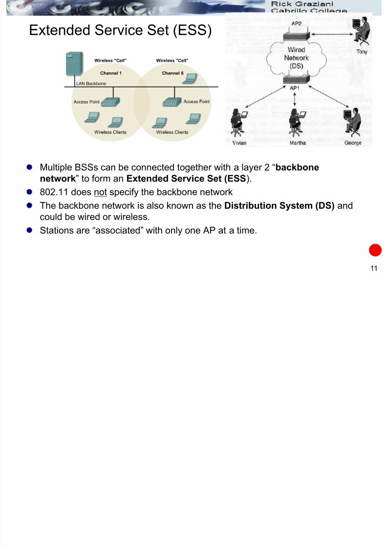
Extended Service Set (ESS)
Multiple BSSs can be connected together with a layer 2 ―backbone
network‖ to form an Extended Service Set (ESS).
802.11 does not specify the backbone network
The backbone network is also known as the Distribution System (DS) and
could be wired or wireless.
Stations are ―associated‖ with only one AP at a time.

7/28/2019 Cis187 Switch 7 Wlan
http://slidepdf.com/reader/full/cis187-switch-7-wlan 12/100
12
Access Points
Access Point (AP)
Translates (converts) 802.11 frames to Ethernet and visa versa
Known as a translation bridge Typically provides wireless-to-wired bridging function
All BSS communications must go through the AP, even between two
wireless stations

7/28/2019 Cis187 Switch 7 Wlan
http://slidepdf.com/reader/full/cis187-switch-7-wlan 13/100
13
Quick Preview: Station/AP Connectivity
SSID (Service Set Identity) At a minimum a client station and
the access point must be configured
to be using the same SSID.
An SSID is:
Between 2 and 32 alphanumericcharacters
Spaces okay
Must match EXACTLY, including
upper and lower case
Sometimes called the ESSID
Not the same as BSSID (MAC
address of the AP, later )

7/28/2019 Cis187 Switch 7 Wlan
http://slidepdf.com/reader/full/cis187-switch-7-wlan 14/100
14
Using NetStumbler
Looking for an AP?

7/28/2019 Cis187 Switch 7 Wlan
http://slidepdf.com/reader/full/cis187-switch-7-wlan 15/100
802.11 Medium Access
Mechanisms
DCF Operations
Hidden Node Problem
RTS/CTS
Frame Fragmentation

7/28/2019 Cis187 Switch 7 Wlan
http://slidepdf.com/reader/full/cis187-switch-7-wlan 16/100
16
802.11 Frames – This isn’t Ethernet!
802.11 has some similarities with Ethernet but it is a different protocol.
Access Points are translation bridges.
Distribution System (DS)
General 802.11 Frame
IP Packet
IP PacketL
L
C
7/28/2019 Cis187 Switch 7 Wlan
http://slidepdf.com/reader/full/cis187-switch-7-wlan 17/100
17
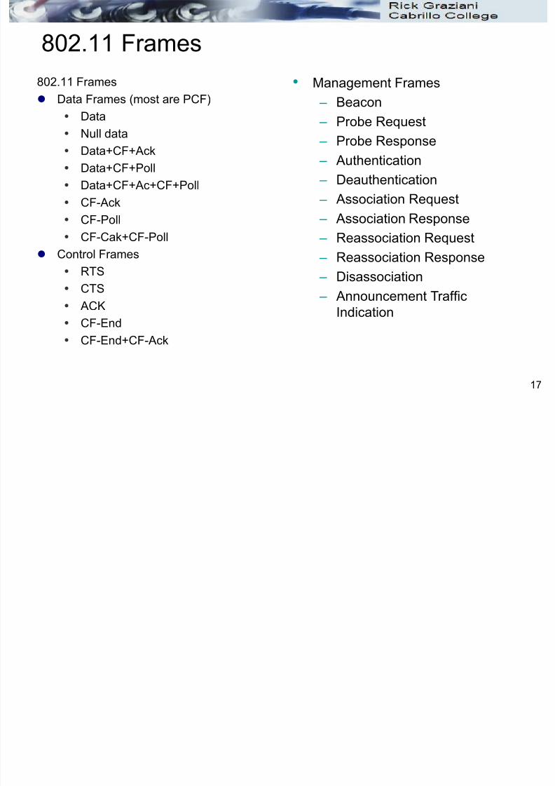
802.11 Frames
802.11 Frames
Data Frames (most are PCF)
Data
Null data
Data+CF+Ack
Data+CF+Poll
Data+CF+Ac+CF+Poll CF-Ack
CF-Poll
CF-Cak+CF-Poll
Control Frames
RTS
CTS
ACK
CF-End
CF-End+CF-Ack
• Management Frames
– Beacon
– Probe Request
– Probe Response
– Authentication
– Deauthentication
– Association Request
– Association Response
– Reassociation Request
– Reassociation Response
– Disassociation
– Announcement Traffic
Indication

7/28/2019 Cis187 Switch 7 Wlan
http://slidepdf.com/reader/full/cis187-switch-7-wlan 18/100
18
Medium Access – CSMA/CA
Both CSMA/CD and CSMA/CA are half-duplex architectures
Ethernet uses CSMA/CD – Collision Detection Ethernet devices detect a collision as when the data is transmitted
802.11 uses CSMA/CA – Collision Avoidance
802.11 devices only detect a collision when the transmitter has not receivedan Acknowledgement.
Stations also use CS/CCA – (see WLAN pres.)
Stations also use a virtual carrier-sense function, NAV (see WLAN pres.)
CSMA/CD CSMA/CA
ACK
All stations detect the
collision

7/28/2019 Cis187 Switch 7 Wlan
http://slidepdf.com/reader/full/cis187-switch-7-wlan 19/100
19
Medium Access – CSMA/CA
The 802.11 standard makes it mandatory that all stations implement the DCF
(Distributed Coordination Function), a form of carrier sense multiple accesswith collision avoidance (CSMA/CA).
The main goal of CSMA/CA is to avoid having stations transmit at the same
time, which will then result in collisions and eventual retransmissions.
However, collisions may still occur and when they do stations may or may not
be able to detect them (hidden node problem).
CSMA/CDCSMA/CA
All stations detect the
collision
ACK

7/28/2019 Cis187 Switch 7 Wlan
http://slidepdf.com/reader/full/cis187-switch-7-wlan 20/100
20
DCF and PCF
IEEE mandated access mechanism for 802.11 is DCF (DistributedCoordination Function)
Basis for CSMA/CA
There is also the PCF (Point Coordination Function) – (See WLAN pres.)
7/28/2019 Cis187 Switch 7 Wlan
http://slidepdf.com/reader/full/cis187-switch-7-wlan 21/100
21
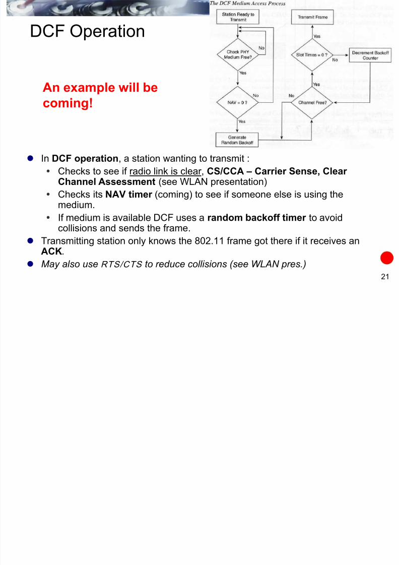
DCF Operation
In DCF operation, a station wanting to transmit :
Checks to see if radio link is clear, CS/CCA – Carrier Sense, Clear Channel Assessment (see WLAN presentation)
Checks its NAV timer (coming) to see if someone else is using the
medium. If medium is available DCF uses a random backoff timer to avoid
collisions and sends the frame.
Transmitting station only knows the 802.11 frame got there if it receives anACK.
May also use RTS/CTS to reduce collisions (see WLAN pres.)
An example will be
coming!
7/28/2019 Cis187 Switch 7 Wlan
http://slidepdf.com/reader/full/cis187-switch-7-wlan 22/100
22
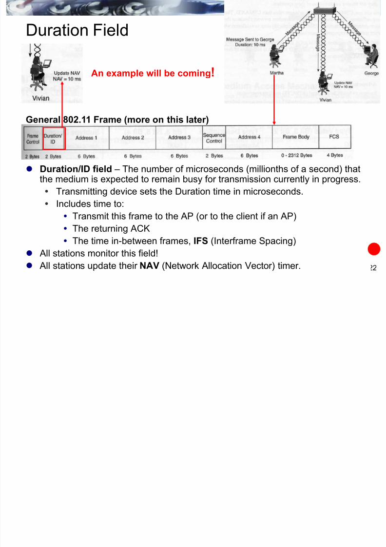
Duration Field
Duration/ID field – The number of microseconds (millionths of a second) thatthe medium is expected to remain busy for transmission currently in progress.
Transmitting device sets the Duration time in microseconds.
Includes time to:
Transmit this frame to the AP (or to the client if an AP)
The returning ACK
The time in-between frames, IFS (Interframe Spacing)
All stations monitor this field!
All stations update their NAV (Network Allocation Vector) timer.
General 802.11 Frame (more on this later)
An example will be coming!

7/28/2019 Cis187 Switch 7 Wlan
http://slidepdf.com/reader/full/cis187-switch-7-wlan 23/100
23
NAV Timer
All stations have a NAV (Network Allocation Vector) timer .
Virtual carrier-sensing function
Protects the sequence of frames from interruption.
Martha sends a frame to George.
Since wireless medium is a ―broadcast-based‖ (not broadcast frame) shared medium, allstations including Vivian receive the frame.
Vivian updates her NAV timer with the duration value.
Vivian will not attempt to transmit until her NAV is decremented to 0.
Stations will only update their NAV when the duration field value received is greater thantheir current NAV.
General 802.11 Frame (more on this later)
An example will be coming!

7/28/2019 Cis187 Switch 7 Wlan
http://slidepdf.com/reader/full/cis187-switch-7-wlan 24/100
24
Broadcast-based shared medium
Host A is sending 802.11
frames to another host viathe AP.
All other 802.11 devices inBSS (on this channel) andwithin range of the signalwill see the frame.
802.11 framing providesaddressing, so only the APknows it is the next-hopreceiver.
Other 802.11 deviceswithin this BSS can sense
that the medium is in useand will update their NAVvalues.
What if a station is in range of the AP but not
the Host A? (Hidden node problem – see
WLAN pres.)

7/28/2019 Cis187 Switch 7 Wlan
http://slidepdf.com/reader/full/cis187-switch-7-wlan 25/100
25
Interframe Spacing (IFS)
802.11 uses four different interframe spaces used to determine medium access (note:microsecond = millionth of a second):
DIFS – DCF Interface Space
Minimum amount of medium idle time until contention-based services begin.
PIFS – PCF Interframe Space Used by PCF (See WLAN pres.)
SIFS – Short Interframe Space
Used for highest priority transmission, ACKs, RTS, CTS (See WLAN pres.)
EIFS – Extended Interframe Space
Not a fixed interval and used only when there is an error in frame transmission.
(See WLAN pres.)
An example will be coming!

7/28/2019 Cis187 Switch 7 Wlan
http://slidepdf.com/reader/full/cis187-switch-7-wlan 26/100
26
Example
Scenario:
Both Vivian and George want to transmit frames.
Both stations have same NAV values and physically sense when the medium
is idle.
Both are waiting for Martha’s transmission to end and the medium to become
available.
The medium now becomes available.
I’m
waiting
I’m
waiting
7/28/2019 Cis187 Switch 7 Wlan
http://slidepdf.com/reader/full/cis187-switch-7-wlan 27/100
27
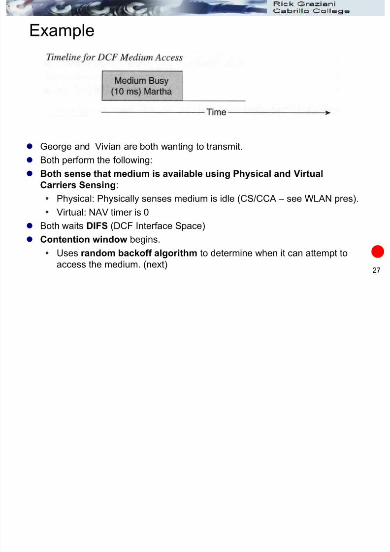
Example
George and Vivian are both wanting to transmit.
Both perform the following:
Both sense that medium is available using Physical and Virtual
Carriers Sensing:
Physical: Physically senses medium is idle (CS/CCA – see WLAN pres). Virtual: NAV timer is 0
Both waits DIFS (DCF Interface Space)
Contention window begins.
Uses random backoff algorithm to determine when it can attempt to
access the medium. (next)
Random backoff slots

7/28/2019 Cis187 Switch 7 Wlan
http://slidepdf.com/reader/full/cis187-switch-7-wlan 28/100
28
Example
Both Vivian and George calculate their random backoff algorithm to
randomly selects a value from 0 to 255.
Vivian has a slot time of 7
George a slot time of 31. Vivian wins!
The destination of her frame is George (could have been a station on the wired
network.)
Vivian (7), George (31)
7/28/2019 Cis187 Switch 7 Wlan
http://slidepdf.com/reader/full/cis187-switch-7-wlan 29/100
29
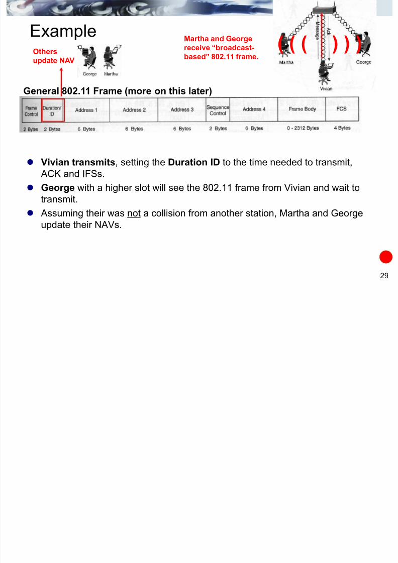
Example
Vivian transmits, setting the Duration ID to the time needed to transmit,
ACK and IFSs.
George with a higher slot will see the 802.11 frame from Vivian and wait to
transmit.
Assuming their was not a collision from another station, Martha and George
update their NAVs.
General 802.11 Frame (more on this later)
Others
update NAV
Martha and George
receive “broadcast-
based” 802.11 frame.
( ( ( ) ) )

7/28/2019 Cis187 Switch 7 Wlan
http://slidepdf.com/reader/full/cis187-switch-7-wlan 30/100
30
Example
The frame arrives at the AP.
After the SIFS:
The AP sends an ACK back to Vivian, which is how Vivianknows the frame was received by the AP.
The AP now has the frame and m ust co ntend for access to the
medium l ike all other stat ions.
Remember, 802.11 uses a half-duplex, shared medium and the AP
has to contend for access just like all other devices!

7/28/2019 Cis187 Switch 7 Wlan
http://slidepdf.com/reader/full/cis187-switch-7-wlan 31/100
802.11 Data Frames and
Addressing

7/28/2019 Cis187 Switch 7 Wlan
http://slidepdf.com/reader/full/cis187-switch-7-wlan 32/100
32
Ethernet MAC Addressing
Distribution System (DS)
A C
D
Access Point 1 Access Point 2
X
Y
xxx
yyy
yyy Pseudo MAC address of hosts
xxx
B
IP Packet
yyyxxx

7/28/2019 Cis187 Switch 7 Wlan
http://slidepdf.com/reader/full/cis187-switch-7-wlan 33/100
33
802.11 MAC Addressing
Four address fields
The address of these fields is dependent upon the source and destinationfor the 802.11 frame.
Address 4 is optional and not commonly used, except for WDS (wirelessdistribution system, bridge to bridge).
General 802.11 Frame
The LLC encapsulation will be
explained later in this presentation.
7/28/2019 Cis187 Switch 7 Wlan
http://slidepdf.com/reader/full/cis187-switch-7-wlan 34/100
34
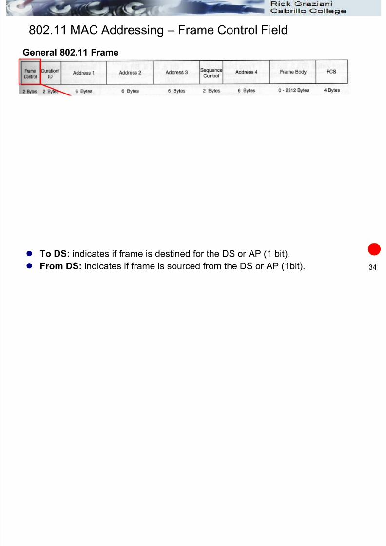
802.11 MAC Addressing – Frame Control Field
To DS: indicates if frame is destined for the DS or AP (1 bit).
From DS: indicates if frame is sourced from the DS or AP (1bit).
General 802.11 Frame

7/28/2019 Cis187 Switch 7 Wlan
http://slidepdf.com/reader/full/cis187-switch-7-wlan 35/100
35
802.11 MAC Addressing – Frame Control Field
Function ToDS FromDS
IBSS (no AP) 0 0
To AP 1 0
From AP 0 1
Wireless bridge to bridge 1 1
General 802.11 Frame
Note: Some
documentation is
misleading stating that the
ToDS is set to 1 only when
the destination is on the
wired side of the AP.
7/28/2019 Cis187 Switch 7 Wlan
http://slidepdf.com/reader/full/cis187-switch-7-wlan 36/100
36
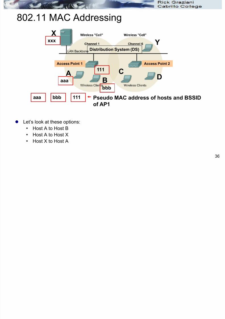
802.11 MAC Addressing
Let’s look at these options:
Host A to Host B
Host A to Host X
Host X to Host A
Distribution System (DS)
AB
C
D
Access Point 1 Access Point 2
X
Y
aaa bbb 111 Pseudo MAC address of hosts and BSSID
of AP1
aaa
bbb
xxx
111
X

7/28/2019 Cis187 Switch 7 Wlan
http://slidepdf.com/reader/full/cis187-switch-7-wlan 37/100
37
802.11 MAC
Addressing
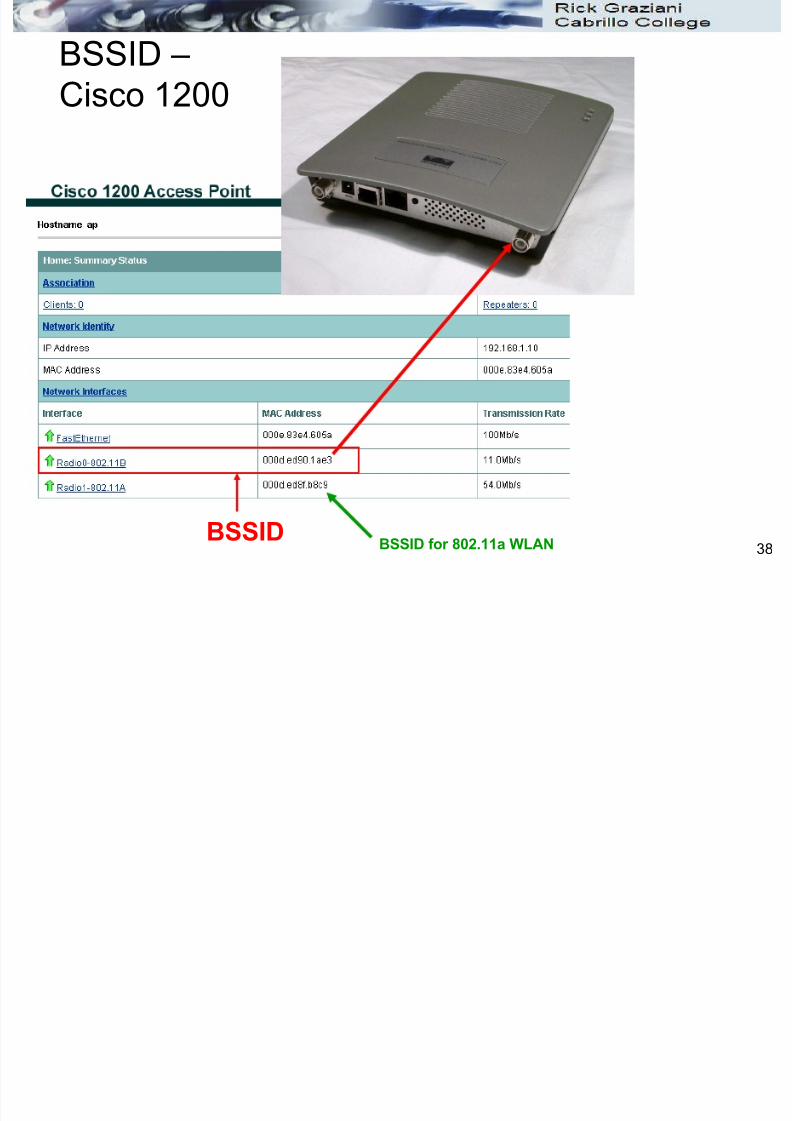
Each BSS is assigned a BSSID.
Not to be confused with SSID or ESSID.
BSSID – 48 bit identifier which distinguishes it from other BSSs in the network,
used for filtering. In a BSS, the BSSID is the MAC address of the wireless interface.
Remember, normal switches (bridges) may have MAC addresses, but these addresses are only used for management purposes and not for layer 2 frame forwarding (addressing).
Distribution System (DS)
AB
CD
Access Point 1 Access Point 2
X
Y
General 802.11 Frame aaabbb
xxx
The BSSID 111
7/28/2019 Cis187 Switch 7 Wlan
http://slidepdf.com/reader/full/cis187-switch-7-wlan 38/100
38
BSSID –
Cisco 1200
BSSID BSSID for 802.11a WLAN
X
7/28/2019 Cis187 Switch 7 Wlan
http://slidepdf.com/reader/full/cis187-switch-7-wlan 39/100
39
802.11 MAC
Addressing
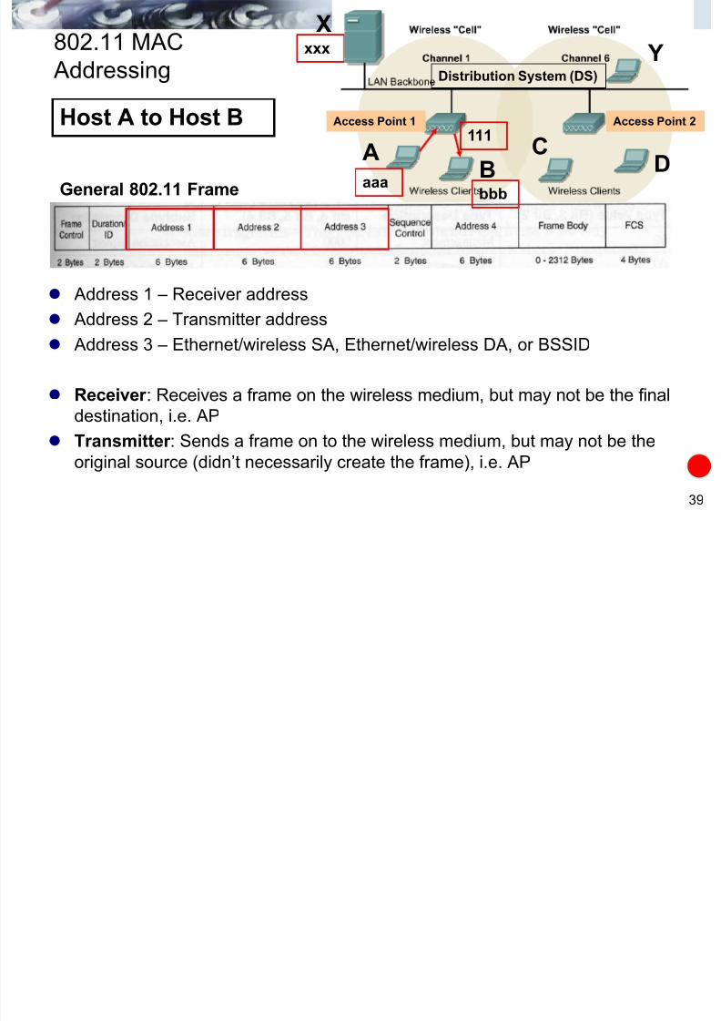
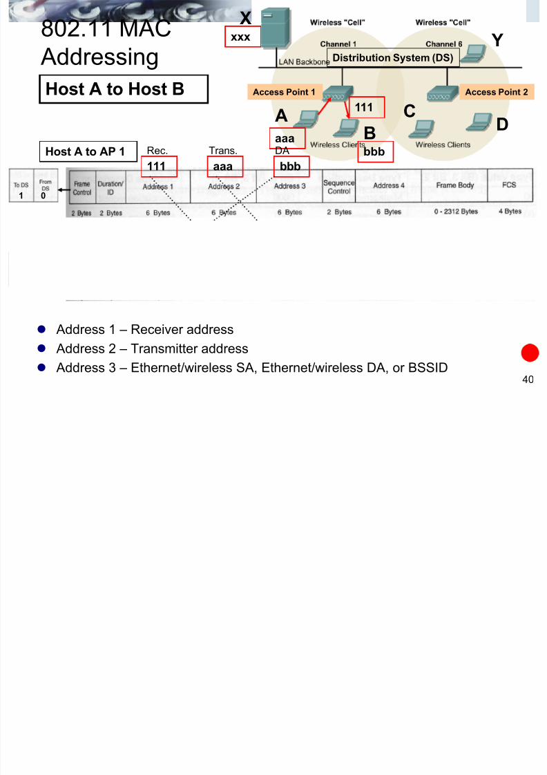
Address 1 – Receiver address
Address 2 – Transmitter address
Address 3 – Ethernet/wireless SA, Ethernet/wireless DA, or BSSID
Receiver : Receives a frame on the wireless medium, but may not be the final
destination, i.e. AP
Transmitter : Sends a frame on to the wireless medium, but may not be the
original source (didn’t necessarily create the frame), i.e. AP
Distribution System (DS)
AB
CD
Access Point 1 Access Point 2
X
Y
General 802.11 Frame
Host A to Host B
aaabbb
xxx
111
X
7/28/2019 Cis187 Switch 7 Wlan
http://slidepdf.com/reader/full/cis187-switch-7-wlan 40/100
40
802.11 MAC
Addressing
Address 1 – Receiver address
Address 2 – Transmitter address
Address 3 – Ethernet/wireless SA, Ethernet/wireless DA, or BSSID
Distribution System (DS)
AB
CD
Access Point 1 Access Point 2
X
Y
Host A to Host B
aaabbb
aaa111 bbb
Host A to AP 1
AP1 to Host B111bbb aaa
xxx
Trans.Rec.
Rec. Trans.
DA
SA
111
1 0
0 1

7/28/2019 Cis187 Switch 7 Wlan
http://slidepdf.com/reader/full/cis187-switch-7-wlan 41/100
41
802.11 MAC Addressing
Access Points are translation bridges.
From 802.11 to Ethernet, and from Ethernet to 802.11
The ―data/frame body‖ is re-encapsulated with the proper layer 2 frame
(Ethernet or 802.11). Certain addresses are copied between the two types of frames.
Distribution System (DS)
General 802.11 Frame
IP Packet
IP PacketL
L
C
X

7/28/2019 Cis187 Switch 7 Wlan
http://slidepdf.com/reader/full/cis187-switch-7-wlan 42/100
42
802.11 MAC
Addressing Distribution System (DS)
AB
CD
Access Point 1 Access Point 2
X
Y
Host A to Host X
aaa
bbb
aaa111 xxx
Host A to AP 1
AP 1 to Host X
aaaxxx
802.11 Frame
• The Ethernet DA and SA are the source and destination addresses just like ontraditional Ethernet networks.
– Destination Address – Host X
– Source Address – Host A
xxx
Rec. Trans. DA
111
1 0
802 11 MACX
7/28/2019 Cis187 Switch 7 Wlan
http://slidepdf.com/reader/full/cis187-switch-7-wlan 43/100
43
802.11 MAC
Addressing Distribution System (DS)
AB
CD
Access Point 1 Access Point 2
X
Y
Host A to Host X
aaa
bbb
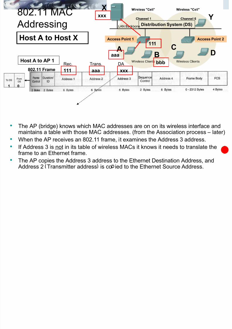
• The AP (bridge) knows which MAC addresses are on on its wireless interface andmaintains a table with those MAC addresses. (from the Association process – later)
• When the AP receives an 802.11 frame, it examines the Address 3 address.
• If Address 3 is not in its table of wireless MACs it knows it needs to translate theframe to an Ethernet frame.
• The AP copies the Address 3 address to the Ethernet Destination Address, and Address 2 Transmitter address is co ied to the Ethernet Source Address.
xxx
aaa111 xxx
Host A to AP 1
802.11 Frame
Rec. Trans. DA
AP 1 to Host Xaaaxxx
111
1 0

7/28/2019 Cis187 Switch 7 Wlan
http://slidepdf.com/reader/full/cis187-switch-7-wlan 44/100
44
802.11 MAC Addressing
Distribution System (DS)
A B CD
Access Point 1 Access Point 2
X
Y
Host X to Host A
aaa bbb
xxx
111
X

7/28/2019 Cis187 Switch 7 Wlan
http://slidepdf.com/reader/full/cis187-switch-7-wlan 45/100
45
802.11 MAC
Addressing Distribution System (DS)
AB
CD
Access Point 1 Access Point 2
X
Y
Host X to Host Aaaa
bbb
aaa 111 xxx
AP 1 to Host A
802.11 Frame
Destination Address –
Host XSource Address – Host A
xxx
Host X to AP 1
aaa xxx
SARec. Trans.copied
• The AP (bridge) knows which MAC address on on its wireless interface andmaintains a table with those MAC addresses. (via Association process – later)
• When the AP receives an Ethernet frame, it examines the Destination address.
• If Destination Address is in its table of wireless MACs it knows it needs to translate the frameto an 802.11 frame.
• The AP copies the Destination address to the 802.11 Address 1, and Ethernet Source is
copied to the Address 3 address (SA in this case).
111
0 1

7/28/2019 Cis187 Switch 7 Wlan
http://slidepdf.com/reader/full/cis187-switch-7-wlan 46/100
46
802.11 MAC Addressing
So how do Ethernet switches know where the wireless stations are?
Just like wired stations – using the source address of frames that came from thewireless station via the access point.
Here the switch learns from the incoming Ethernet frame that Source Address aaa is on port 2 and enters that in its MAC address table.
Any frames coming into the switch (ex. port 1) with a Destination Address of aaa,the switch knows to forward those frames out port 2 (towards the AP).
aaa
xxx
aaaxxx
2
1
111

7/28/2019 Cis187 Switch 7 Wlan
http://slidepdf.com/reader/full/cis187-switch-7-wlan 47/100
802.11 MAC Layer Operations
Station Connectivity
Power Save Operations802.11 Frame Formats

7/28/2019 Cis187 Switch 7 Wlan
http://slidepdf.com/reader/full/cis187-switch-7-wlan 48/100
48
Station Connectivity

7/28/2019 Cis187 Switch 7 Wlan
http://slidepdf.com/reader/full/cis187-switch-7-wlan 49/100
49
Station Connectivity
Station connectivity is a explanation of how 802.11 stations select andcommunicate with APs.
State 1
Unauthenticated
Unassociated
State 2
Authenticated
Unassociated
State 3
Authenticated
Associated
Successful
Authentication
Successful
Association
Deauthentication Disassociation

7/28/2019 Cis187 Switch 7 Wlan
http://slidepdf.com/reader/full/cis187-switch-7-wlan 50/100
50
Station Connectivity
Three processes:
Probe Process (or scanning)
The Authentication Process The Association Process
Only after a station has both authenticated and associated with the access
point can it use the Distribution System (DS) services and communicate with
devices beyond the access point.
State 1
Unauthenticated
Unassociated
State 2
Authenticated
Unassociated
State 3
Authenticated
Associated
Successful
Authentication
Successful
Association
Deauthentication Disassociation
Probe
process
Authentication
process
Association
process

7/28/2019 Cis187 Switch 7 Wlan
http://slidepdf.com/reader/full/cis187-switch-7-wlan 51/100
51
Station Connectivity – Probe Process• The Probe Process (Scanning) done
by the wireless station
– Passive - Beacons
– Active – Probe Requests
• Used by client to determine:
• SSID
• Supported data rates
• Security
• Depends on device drive of wireless
adapter or the software utility you are
using.
• Cisco adapters do active scanning when
associating, but use passive scanning for
some tests.
• In either case, beacons are still received
and used by the wireless stations for
other things besides scanning (coming).

7/28/2019 Cis187 Switch 7 Wlan
http://slidepdf.com/reader/full/cis187-switch-7-wlan 52/100
52
Station Connectivity – Passive Scanning
Passive Scanning
Saves battery power
Station moves to each channel andwaits for Beacon frames from the AP.
Records any beacons received.
Beacon frames allow a station to find outevery thing it needs to begin
communications with the AP including: SSID
Supported Rates

7/28/2019 Cis187 Switch 7 Wlan
http://slidepdf.com/reader/full/cis187-switch-7-wlan 53/100
53
Station Connectivity – Active Scanning
Active Scanning: Probe Request
This process is not mandatory on with 802.11. A Probe Request frame is sent out on every
channel (1 – 11) by the client.
APs that receive Probe Requests must reply
with a Probe Response frame if:
From the client
From the AP

7/28/2019 Cis187 Switch 7 Wlan
http://slidepdf.com/reader/full/cis187-switch-7-wlan 54/100
54
Station Connectivity
Station connectivity processes:
Probe Process (or scanning)
The Authentication Process The Association Process
Only after a station has both authenticated and associated with the access
point can it use the Distribution System (DS) services and communicate with
devices beyond the access point.
State 1
Unauthenticated
Unassociated
State 2
Authenticated
Unassociated
State 3
Authenticated
Associated
Successful
Authentication
Successful
Association
Deauthentication Disassociation
Probe
process
Authentication
process
Association
process
7/28/2019 Cis187 Switch 7 Wlan
http://slidepdf.com/reader/full/cis187-switch-7-wlan 55/100
55
Authentication Process
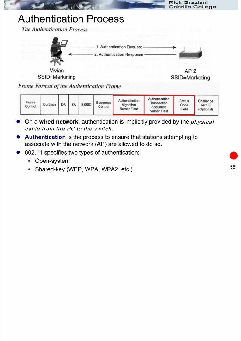
On a wired network, authentication is implicitly provided by the phys ical
cable from th e PC to the switch .
Authentication is the process to ensure that stations attempting to
associate with the network (AP) are allowed to do so.
802.11 specifies two types of authentication:
Open-system
Shared-key (WEP, WPA, WPA2, etc.)

7/28/2019 Cis187 Switch 7 Wlan
http://slidepdf.com/reader/full/cis187-switch-7-wlan 56/100
56
Station Connectivity
Station connectivity processes:
Probe Process (or scanning)
The Authentication Process The Association Process
Only after a station has both authenticated and associated with the access
point can it use the Distribution System (DS) services and communicate with
devices beyond the access point.
State 1
Unauthenticated
Unassociated
State 2
Authenticated
Unassociated
State 3
Authenticated
Associated
Successful
Authentication
Successful
Association
Deauthentication Disassociation
Probe
process
Authentication
process
Association
process
7/28/2019 Cis187 Switch 7 Wlan
http://slidepdf.com/reader/full/cis187-switch-7-wlan 57/100
57
Association Process
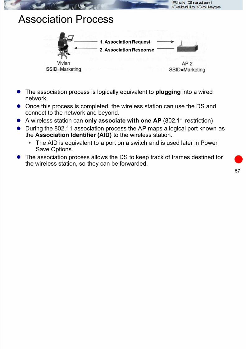
The association process is logically equivalent to plugging into a wirednetwork.
Once this process is completed, the wireless station can use the DS andconnect to the network and beyond.
A wireless station can only associate with one AP (802.11 restriction)
During the 802.11 association process the AP maps a logical port known asthe Association Identifier (AID) to the wireless station.
The AID is equivalent to a port on a switch and is used later in Power Save Options.
The association process allows the DS to keep track of frames destined for the wireless station, so they can be forwarded.
1. Association Request
2. Association Response

7/28/2019 Cis187 Switch 7 Wlan
http://slidepdf.com/reader/full/cis187-switch-7-wlan 58/100
58
Power Save (PS) Operations
A key factor in wireless is mobility, which implies batteries.
To preserve battery power the 802.11 specification provides for power saving
operations on the wireless clients.
802.11 categories for power savings refer to:
Unicast frames
Broadcast/Multicast frames

7/28/2019 Cis187 Switch 7 Wlan
http://slidepdf.com/reader/full/cis187-switch-7-wlan 59/100
59
Power Save (PS) Operations
The Cisco ACU has three options for Power Saving:
CAM (Constantly Awake Mode)
MAX PSP (Max Power Savings)
Fast PSP (Fast Power Saving Mode)
(see WLAN pres).

7/28/2019 Cis187 Switch 7 Wlan
http://slidepdf.com/reader/full/cis187-switch-7-wlan 60/100
60
Power Save (PS) Operations
A client enters low-power mode by turning off its radio.
The AP buffers (holds) frames destined for that station while it is in PS
mode. At a certain interval the client wakes up to listen for a beacon from the AP.
The beacon contains information on whether or not there are frames for thisstation at the AP.
If there are no frames buffered for this station it can return to PS mode.
beacon
I’m awake. Let me listen for a
beacon to see if there is any
traffic for me.If not, I can go back to sleep.

7/28/2019 Cis187 Switch 7 Wlan
http://slidepdf.com/reader/full/cis187-switch-7-wlan 61/100
61
Power Save (PS) Operations
The basics:
If there are frames buffered for this station it will poll the AP for those
frames.
The AP will then send the frames to the station.
Beacon (frames buffered)
There are frames for me!
Please send them to me.
PS-Poll (send them to me)
Frame 1
ACK
7/28/2019 Cis187 Switch 7 Wlan
http://slidepdf.com/reader/full/cis187-switch-7-wlan 62/100
62
802.11 Frame Formats (Some of them)
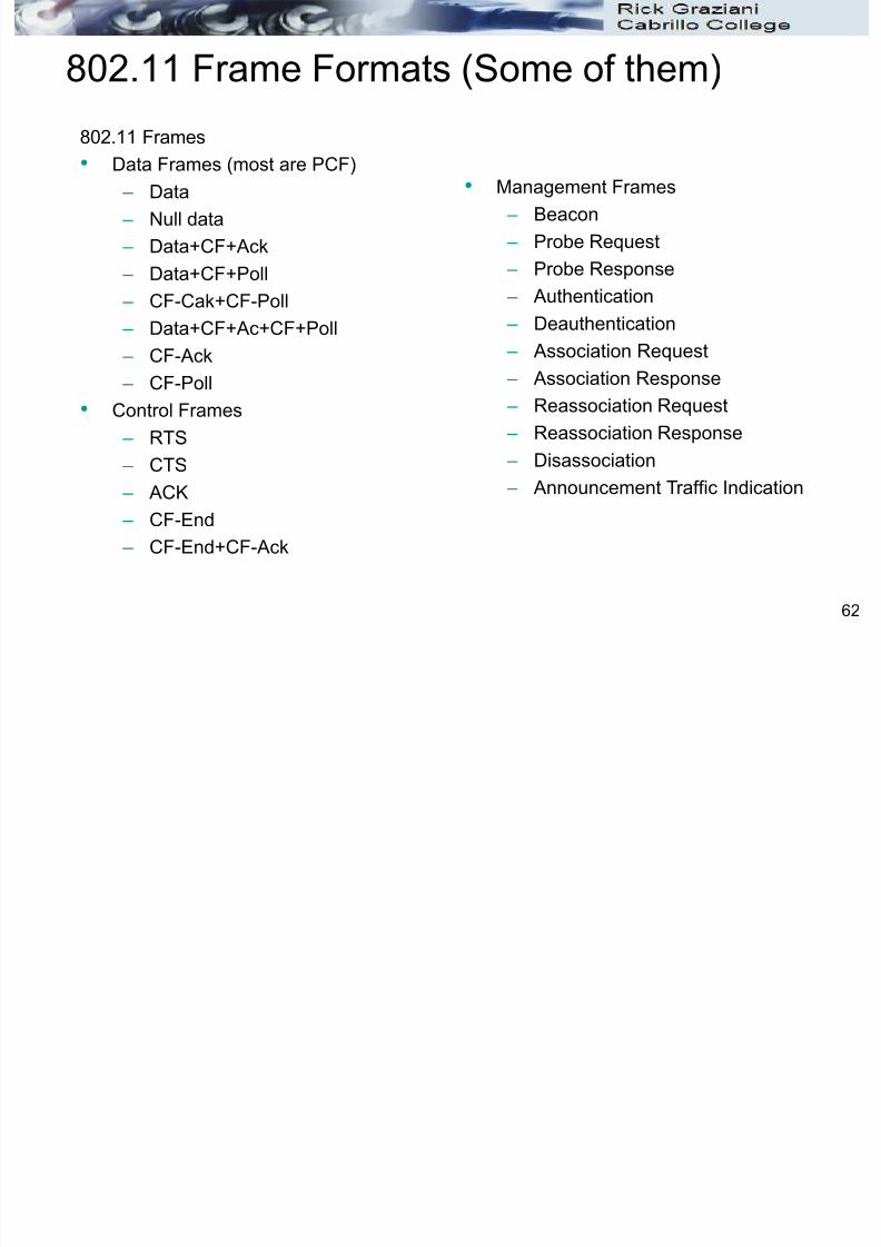
802.11 Frames
• Data Frames (most are PCF)
– Data
– Null data
– Data+CF+Ack
– Data+CF+Poll
– CF-Cak+CF-Poll – Data+CF+Ac+CF+Poll
– CF-Ack
– CF-Poll
• Control Frames
– RTS
– CTS
– ACK
– CF-End
– CF-End+CF-Ack
• Management Frames
– Beacon
– Probe Request
– Probe Response
– Authentication
– Deauthentication
– Association Request
– Association Response
– Reassociation Request
– Reassociation Response
– Disassociation – Announcement Traffic Indication

7/28/2019 Cis187 Switch 7 Wlan
http://slidepdf.com/reader/full/cis187-switch-7-wlan 63/100
Integrating WLANs

7/28/2019 Cis187 Switch 7 Wlan
http://slidepdf.com/reader/full/cis187-switch-7-wlan 64/100
64
Mapping VLANs to SSIDs
AP is a translational bridge, bridging tow dissimilar mediums.
AP is in charge of mapping a VLAN to an SSID.
For multiple VLANs (SSIDs) a trunk will need bo be created
between the AP and the switch.
VLAN 10VLAN 10
VLAN 20
SSID “Marketing” SSID “Marketing” SSID “Engineering”
Access
VLAN 10
Trunk
VLAN 10, 20

7/28/2019 Cis187 Switch 7 Wlan
http://slidepdf.com/reader/full/cis187-switch-7-wlan 65/100
65
WLAN Cells
When APs overlap, adjacent APs cannot use identical frequenciesotherwise you have interference.
Roaming: A client moving from one AP to another.
Any data that the client was sending needs to be relayed from one AP to thenew AP.

7/28/2019 Cis187 Switch 7 Wlan
http://slidepdf.com/reader/full/cis187-switch-7-wlan 66/100
66
Roaming
Layer 2 roaming: A WLAN device moves, the or ig inal and the new AP
offer coverage for the same IP sub net , so the device’s IP address is still be
valid after the roam.
Layer 3 roaming: Client moves from an AP that covers one IP subnet to an
AP that cov ers another IP subn et .
Would mean a new IP address and default gateway that are valid
within the new AP’s IP subnet
Causes existing data sessions or voice sessions to fail.
Solution: Cisco Unified Wireless Network and Intercontroller roaming.

7/28/2019 Cis187 Switch 7 Wlan
http://slidepdf.com/reader/full/cis187-switch-7-wlan 67/100
WLAN Architecture

7/28/2019 Cis187 Switch 7 Wlan
http://slidepdf.com/reader/full/cis187-switch-7-wlan 68/100
68
Traditional WLAN Architecture
Traditional WLAN each AP serves
as the central hub for its own BSS. Each AP must be configured
individually for network policiesincluding:
Radio frequency (RF)
Security policies Authentication and association
Monitoring traffic
QoS
Bandwidth policing
Rogue AP detection Cisco calls this an autonomous
mode AP.
Traffic patterns for an autonomous AP are completely handled by the AP.
BSS
Range

7/28/2019 Cis187 Switch 7 Wlan
http://slidepdf.com/reader/full/cis187-switch-7-wlan 69/100
69
Traditional WLAN Architecture
AP can support multiple SSIDs if multiple VLANs are extended to it over a trunk link.
If you want to offer the same SSIDs from several automous APs, the VLANS must beextended to the APs in a contiguous manner.
Problem is that the SSID and its VLAN would have to be extended everywhere the user could possibly roam.
This would cause end-to-end or campus-wide VLANs which is not good networkdesign practice.
SwitchedRouted

7/28/2019 Cis187 Switch 7 Wlan
http://slidepdf.com/reader/full/cis187-switch-7-wlan 70/100
70
Cisco Unified Wireless Network Architecture
Cisco Unified Wireless Network Architecture centralizes many
traditional capabilities moving many functions to a central locationincluding:
WLAN security
WLAN deployment
WLAN management
WLAN control
Real-time Processes Real-time ProcessesManagement Processes Management Processes
RF Transmit/Receive
MAC ManagementEncryption
RF Transmit/Receive
MAC ManagementEncryption
RF Management
Association & RoamingManagement
Client Authentication
Security Management
QoS
RF Management
Association & RoamingManagement
Client Authentication
Security Management
QoS
LWAPP or
CAPWAP Tunnel
Traditional WLAN
Cisco Unified Wireless Network

7/28/2019 Cis187 Switch 7 Wlan
http://slidepdf.com/reader/full/cis187-switch-7-wlan 71/100
71
Cisco Unified Wireless Network Architecture
Real-time processes include:
Sending/receiving 802.11 frames, AP beacons, probes, dataencryption.
Management processes include:
RF management, roaming management, QoS, security.
Including all those association, authentication, power saving, etc.
tasks we saw previously.
Real-time Processes Real-time ProcessesManagement Processes Management Processes
RF Transmit/Receive
MAC ManagementEncryption
RF Transmit/Receive
MAC ManagementEncryption
RF Management
Association & RoamingManagement
Client Authentication
Security Management
QoS
RF Management
Association & RoamingManagement
Client Authentication
Security Management
QoS
LWAPP or
CAPWAP Tunnel
Traditional WLAN
Cisco Unified Wireless Network
C f

7/28/2019 Cis187 Switch 7 Wlan
http://slidepdf.com/reader/full/cis187-switch-7-wlan 72/100
72
Cisco Unified Wireless Network Architecture
LAP or LWAP (Lightweight Access Point)
Performs only the real-time 802.11 operations.
Layer 1 and 2 operations
The IOS image and local intelligence is stripped down compared to
autonomous APs.
Dependent upon the WLC for all other operations.
WLC (Wireless LAN Controller)
Performs all management functions
This is known as split-MAC architecture
Control Messages
Encapsulated Data
LWAPP or CAPWAP
LWAPP or CAPWAP
LAP WLC
Ci U ifi d Wi l N t k A hit t

7/28/2019 Cis187 Switch 7 Wlan
http://slidepdf.com/reader/full/cis187-switch-7-wlan 73/100
73
Cisco Unified Wireless Network Architecture
Two devices have a LWAPP or CAPWAP tunnel to exchange 802.11
messages and client data.
LAP and WLC can be in the same VLAN/IP subnet or different ones.
The LWAPP or CAPWAP tunnel allows user data to be switched or routedacross the campus network.
LWAPP (Lightweight Access Point Protocol)
Developed by Cisco, submitted as draft RFC 4118
CAPWAP (Control and Provisioning Wireless Access Points protocol)
The resulting standard.
Ci U ifi d Wi l N t k A hit t
7/28/2019 Cis187 Switch 7 Wlan
http://slidepdf.com/reader/full/cis187-switch-7-wlan 74/100
74
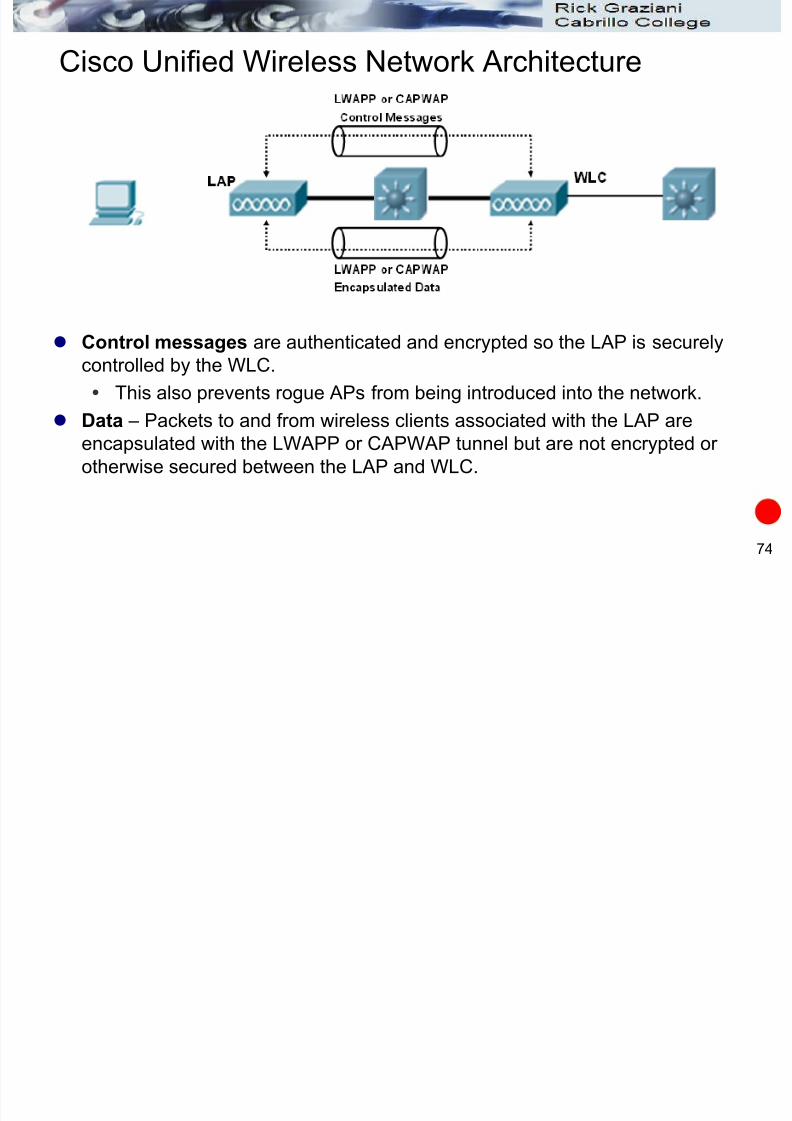
Cisco Unified Wireless Network Architecture
Control messages are authenticated and encrypted so the LAP is securely
controlled by the WLC.
This also prevents rogue APs from being introduced into the network.
Data – Packets to and from wireless clients associated with the LAP areencapsulated with the LWAPP or CAPWAP tunnel but are not encrypted or
otherwise secured between the LAP and WLC.
Ci U ifi d Wi l N t k A hit t

7/28/2019 Cis187 Switch 7 Wlan
http://slidepdf.com/reader/full/cis187-switch-7-wlan 75/100
75
Cisco Unified Wireless Network Architecture
WLC (Wireless LAN Controller) functions:
Dynamic channel assignment – Chooses and configures RF channel for each LAP.
Transmit power optimization – Sets transmit power for each LAP based on size of coverage area needed.
Self-healing wireless coverage – If a LAP radio dies other LAPs can have their power
increased. Flexible client roaming – Manages Layer 2 and 3 roaming.
Dynamic client load balancing – If multiple LAPs are in same coverage area, WLC canassociate clients with the least used LAP.
RF monitoring – Scans channels to monitor RF usage, interference, noise, and signalsfrom regue APs.
Security management – Require clients to get their IP address from a trusted DHCPserver before allowing them to associate.
Ci U ifi d Wi l N t k A hit t
7/28/2019 Cis187 Switch 7 Wlan
http://slidepdf.com/reader/full/cis187-switch-7-wlan 76/100
76
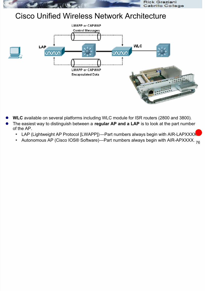
Cisco Unified Wireless Network Architecture
WLC available on several platforms including WLC module for ISR routers (2800 and 3800).
The easiest way to distinguish between a regular AP and a LAP is to look at the part number of the AP.
LAP (Lightweight AP Protocol [LWAPP])—Part numbers always begin with AIR-LAPXXXX.
Autonomous AP (Cisco IOS® Software)—Part numbers always begin with AIR-APXXXX.
Ci U ifi d Wi l N t k A hit t

7/28/2019 Cis187 Switch 7 Wlan
http://slidepdf.com/reader/full/cis187-switch-7-wlan 77/100
77
Cisco Unified Wireless Network Architecture
Cisco Wireless Control System (WCS)
Optional - Allows for easier management of several WLCs.
Server platform which uses a GUI front-end.
Uses floor plans to display dynamic representations of wireless coverage.
Can be used with Cisco Wireless Location Appliance to track the location of
thousands of clients.
WCS
Ci U ifi d Wi l N t k A hit t

7/28/2019 Cis187 Switch 7 Wlan
http://slidepdf.com/reader/full/cis187-switch-7-wlan 78/100
78
Cisco Unified Wireless Network Architecture
LAPs (Lightweight Access Point) are designed to be “zero touch” configuration.
Gets is configuration parameters from the WLC Do not need to configure it through its console port or over the network.
LAP Operations
Step 1: LAP obtains an IP address from DHCP server
Step 2: LAP learns IP address of an available WLCs
DHCP server adds option 43 to its reply containing a list of WLCs, or
LAP broadcasts a join request message (as long as the WLC on the localsubnet)
Step 3: LAP sends a join request to the first WLC in its list.
Step 4: WLC compares IOS image number stored to the one stored on the WLC.If they differ the LAP download the code on the WLC and reboots.
Step 5: WLCP and LAP build a secure LWAPP or CAPWAP tunnel for management traffic, and LWAPP or CAPWAP tunnel (not secured) for wireless
client data.
DHCP Server
HREAP

7/28/2019 Cis187 Switch 7 Wlan
http://slidepdf.com/reader/full/cis187-switch-7-wlan 79/100
79
HREAP
When LAP is cut off from WLC client associations are dropped and
no data can pass over the WLAN.
Cisco Hybrid Remote Edge Access Point (HREAP) is used when
LAPs are separated from WLCS over a WAN link. The LAPs can keep operating even while the WAN link is down and
the WLC is not available – like an autonomous AP.
Allows wireless clients to keep communicating within the remote
site.
WLC

7/28/2019 Cis187 Switch 7 Wlan
http://slidepdf.com/reader/full/cis187-switch-7-wlan 80/100
Traffic Patterns
Single VLANs

7/28/2019 Cis187 Switch 7 Wlan
http://slidepdf.com/reader/full/cis187-switch-7-wlan 81/100
81
Single VLANs
Traffic patterns differ than traditional
WLANs.
Client data passes:
From Client A to LAP
From LAP to WLC
From WLC back to LAP From LAP to Client B
Encryption is still handled between
the LAP and the client.
BSS
Range
Multiple VLANs

7/28/2019 Cis187 Switch 7 Wlan
http://slidepdf.com/reader/full/cis187-switch-7-wlan 82/100
82
Multiple VLANs
With traditional WLANs the access VLANs must be extended or trunked between APsand multilayer switch.
This is not the case with LAPs and WLCs.
There are two VLANs A and B with their respective SSIDs A and B.
The VLANs exist on the trunk between the MLC and SW2 but go no further.
The LAPs and the WLC are connected by VLAN Z which is can be totally isolatedfrom VLANs A and B.
VLANs A and B are carried over the LWAPP tunnel so they are logically connectedbetween the LAP and the WLC.

7/28/2019 Cis187 Switch 7 Wlan
http://slidepdf.com/reader/full/cis187-switch-7-wlan 83/100
Roaming in a Cisco Unified
Wireless Network
T diti l

7/28/2019 Cis187 Switch 7 Wlan
http://slidepdf.com/reader/full/cis187-switch-7-wlan 84/100
84
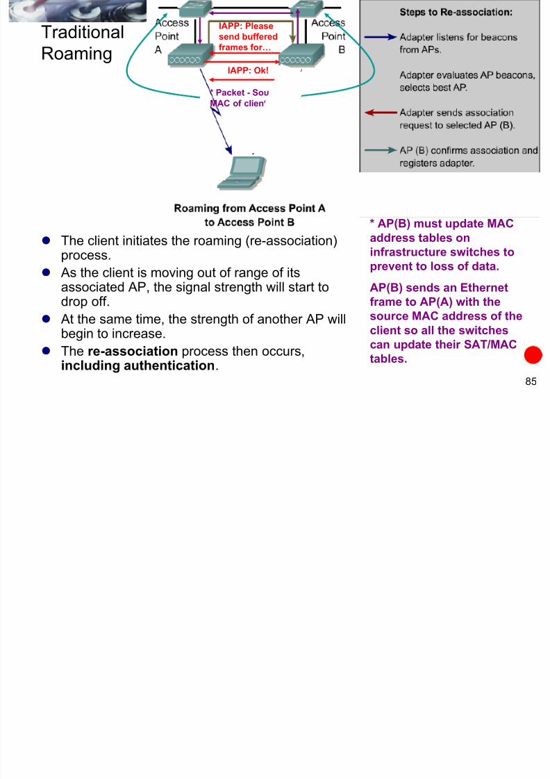
Traditional
Roaming
A WLAN designer must determine whether clients will require seamlessroaming from access point to access point.
IEEE 802.11 IAPP (Inter-Access Point Protocol). Initial Association:
Probing (Probe Request, Probe Response)
Authentication (Authentication Request, Authentication Response)
Association (Association Request, Association Response)
802.11 does not allow associating with more than one AP.
TraditionalIAPP: Please
send buffered
7/28/2019 Cis187 Switch 7 Wlan
http://slidepdf.com/reader/full/cis187-switch-7-wlan 85/100
85
Roaming
The client initiates the roaming (re-association)process.
As the client is moving out of range of its
associated AP, the signal strength will start todrop off.
At the same time, the strength of another AP willbegin to increase.
The re-association process then occurs,including authentication.
frames for…
IAPP: Ok!
* AP(B) must update MAC
address tables on
infrastructure switches to
prevent to loss of data.
AP(B) sends an Ethernetframe to AP(A) with the
source MAC address of the
client so all the switches
can update their SAT/MAC
tables.
* Packet - Source
MAC of client…
Roaming in a Cisco Unified Wireless Network

7/28/2019 Cis187 Switch 7 Wlan
http://slidepdf.com/reader/full/cis187-switch-7-wlan 86/100
86
Roaming in a Cisco Unified Wireless Network
With autonomous APs when a client roams its association moves
from one AP to another.
Client must negotiate the move independently and the APs mustalso make sure any buffered data from the client is passed along
with the association.
WLC supports both Layer 2 and Layer 3 roaming.
Intracontroller Roaming

7/28/2019 Cis187 Switch 7 Wlan
http://slidepdf.com/reader/full/cis187-switch-7-wlan 87/100
87
Intracontroller Roaming
Both LAP1 and LAP2:
Use SSID ―MyWLAN‖
Joined to the same WLC
Client roams into area covered by AP2.
Although the AP has changed the same controller is providing the
association with through the LWAPP or CAPWAP tunnel.
This is known as intracontroller roaming.
Intracontroller Roaming

7/28/2019 Cis187 Switch 7 Wlan
http://slidepdf.com/reader/full/cis187-switch-7-wlan 88/100
88
Intracontroller Roaming
Intracontroller roaming.
The WLC (controller) simply updates its tables to begin using the
LWAPP or CAPWAP tunnel to LAP2.
Any leftover data that was buffered for the prior association with
LAP1 is easily shifted to new association with LAP2.
Intercontroller Roaming (same subnet)
7/28/2019 Cis187 Switch 7 Wlan
http://slidepdf.com/reader/full/cis187-switch-7-wlan 89/100
89
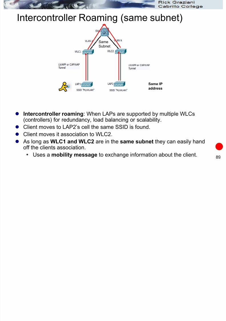
Intercontroller Roaming (same subnet)
Intercontroller roaming: When LAPs are supported by multiple WLCs
(controllers) for redundancy, load balancing or scalability. Client moves to LAP2’s cell the same SSID is found.
Client moves it association to WLC2.
As long as WLC1 and WLC2 are in the same subnet they can easily handoff the clients association.
Uses a mobility message to exchange information about the client.
SameSubnet
Same IP
address
Intercontroller Roaming (same subnet)

7/28/2019 Cis187 Switch 7 Wlan
http://slidepdf.com/reader/full/cis187-switch-7-wlan 90/100
90
Intercontroller Roaming (same subnet)
When the mobility exchange occurs the client begins using the LWAPP or
CAPWAP tunnel between LAP2 and WLC2. Client IP address has n ot changed.
Roaming process completely transparent to the client.
SameSubnet
Mobility
Exchange
Same IP
address
Intercontroller Roaming (different subnet)

7/28/2019 Cis187 Switch 7 Wlan
http://slidepdf.com/reader/full/cis187-switch-7-wlan 91/100
91
Intercontroller Roaming (different subnet)
WLC controllers are in different subnets (VLANs A and B).
Do not have to have end-to-end or campus wide VLANs.
Client begins in cell with association to WLC1.
Obtains an IP address within VLAN A
LAP1 offers VLAN A on its SSID ―MyWLAN‖
All traffic passes between LAP1 and WLC1 onto VLAN A.
MobilityExchange
Same IP
address
Intercontroller Roaming (different subnet)

7/28/2019 Cis187 Switch 7 Wlan
http://slidepdf.com/reader/full/cis187-switch-7-wlan 92/100
92
Intercontroller Roaming (different subnet)
Client roams into cell provided by LAP2.
LAP2 offers access to a different VLAN, VLAN B.
The client’s IP address remains the same.
But WLC1 and WLC2 are in different subnets (VLANs A and B).
Client IP address has moved into a foreign subnet.
Same IP
address
MobilityExchange
Intercontroller Roaming (different subnet)

7/28/2019 Cis187 Switch 7 Wlan
http://slidepdf.com/reader/full/cis187-switch-7-wlan 93/100
93
Intercontroller Roaming (different subnet)
Two WLCs (controllers) begin to work together to provide continue service
for the client without the client needing to obtain an new IP address.
WLCs (controllers) bring up an Ether-IP tunnel (RFC 3378) between them.
Carries some of the clients data traffic
Encapsulates Ethernet frame inside an IP packet using protocol 97.
WLC1 encapsulates packets and sends them to WLC2.
WLC2 unencapsulates the packets into their original form.
Same IP
address
L3 Mobility
Tunnel
MobilityExchange
Intercontroller Roaming (different subnet)

7/28/2019 Cis187 Switch 7 Wlan
http://slidepdf.com/reader/full/cis187-switch-7-wlan 94/100
94
Intercontroller Roaming (different subnet)
Traffic leaving the client travels from LAP2 to WLC2 onto the network even though itis on a foreign subnet.
It’s just a packet in an Ethernet frame.
Dest MAC – Source MAC [ IP Packet: Source IP – Dest IP - ]
Traffic coming in towards the client takes a different path. Traffic enters MLS (L3 switch)
Because the packet has an IP address on VLAN 3 it is routed/switched out VLAN A to WLC1.
WLC1 accepts the traffic and forwards it to the appropriate WLC controller thathas the current association with the client.
WLC1 sends the traffic to WLC2 through the Ether-IP tunnel.
WLC2 forwards the traffic to LAP2 and onto the client.
Same IP
address
L3 Mobility
Tunnel
MobilityExchange
Intercontroller Roaming (different subnet)

7/28/2019 Cis187 Switch 7 Wlan
http://slidepdf.com/reader/full/cis187-switch-7-wlan 95/100
95
Intercontroller Roaming (different subnet)
The client originally joined the WLAN on WLC1, so WLC1 is known as the anchor .
WLC2 is serving a client on a different subnet so it is known as the foreign agent.
As the client continues to roam the foreign agent will change but the anchor will
remain the same. To do this WLCs are configured into logical mobility groups.
Up to 24 WLCs
Number of LAPs vary depending upon LAP platform.
If a client must move between mobility groups, it’s IP address and all of its session
information maintained by the WLC will be dropped.
Same IP
address
L3 Mobility
Tunnel
MobilityExchangeAnchor Foreign
Agent

7/28/2019 Cis187 Switch 7 Wlan
http://slidepdf.com/reader/full/cis187-switch-7-wlan 96/100
Configuring Switch Ports for
WLAN Use
Note: For purposes of the CCNP SWITCH course/exam
you only need to understand the switch configurations
and not the LAP/WLC configurations.
Configuring Switchports for
A t AP

7/28/2019 Cis187 Switch 7 Wlan
http://slidepdf.com/reader/full/cis187-switch-7-wlan 97/100
97
Autonomous APs
APs are normally at the access layer. Each SSID is supported by the AP mapped to a VLAN.
When multiple SSIDs/VLANs are used need to configure switchport as a
trunk.
The is spanning-tree portfast trunk used to shorten the time required
for STP to bring up the trunk link to forwarding state quickly.
Switch(config)# interface gig 0/1
Switch(config-if)# switchport trunk encapsulation dot1q
Switch(config-if)# switchport trunk allowed vlan 10, 20
Switch(config-if)# switchport mode trunkSwitch(config-if)# spanning-tree portfast trunk
gig 0/1
Configuring Switchports for Cisco Unified Wireless Network

7/28/2019 Cis187 Switch 7 Wlan
http://slidepdf.com/reader/full/cis187-switch-7-wlan 98/100
98
Configuring Switchports for Cisco Unified Wireless Network
VLAN 50 is created to access the LAPs.
VLAN 55 is created to access the WLC.
Distribution(config)# vlan 10, 20, 50, 55
Distribution(config)# interface vlan 10 Configure the SVIs
Distribution(config-if)# ip address 172.30.10.1 255.255.255.0
Distribution(config)# interface vlan 20
Distribution(config-if)# ip address 172.30.10.1 255.255.255.0
Distribution(config)# interface vlan 50
Distribution(config-if)# ip address 172.30.50.1 255.255.255.0
Distribution(config)# interface vlan 55
Distribution(config-if)# ip address 172.30.55.1 255.255.255.0
Distribution(config)# interface fa 0/1 <must carry vlan 50>
Distribution(config-if)# switchport trunk encapsulation dot1q
Distribution(config-if)# switchport mode trunk
Distribution(config)# interface gig 1/2 <must carry vlans 10, 20 & 55>
Distribution(config-if)# switchport trunk encapsulation dot1q
Distribution(config-if)# switchport mode trunk
Configuring Switchports for Cisco Unified Wireless Network

7/28/2019 Cis187 Switch 7 Wlan
http://slidepdf.com/reader/full/cis187-switch-7-wlan 99/100
99
Configuring Switchports for Cisco Unified Wireless Network
VLAN 50 is created to access the LAPs.
Access(config)# interface fa 0/1
Access(config-if)# switchport trunk encapsulation dot1q
Access(config-if)# switchport mode trunk
Access(config)# interface fa 0/2
Access(config-if)# switchport mode access
Access(config-if)# switchport access vlan 50
Access(config-if)# spanning-tree portfast
fa 0/2

7/28/2019 Cis187 Switch 7 Wlan
http://slidepdf.com/reader/full/cis187-switch-7-wlan 100/100
CIS 187 Multilayer Switched Networks
(CCNP Switch)
Integrating Wireless LANs
Rick Graziani
Cabrillo College
Spring 2010