Embed Size (px)
Citation preview
Cisco Catalyst Blade Switch 3120 for HP Hardware Installation Guide March 2008
THE SPECIFICATIONS AND INFORMATION REGARDING THE PRODUCTS IN THIS MANUAL ARE SUBJECT TO CHANGE WITHOUT NOTICE. ALL STATEMENTS, INFORMATION, AND RECOMMENDATIONS IN THIS MANUAL ARE BELIEVED TO BE ACCURATE BUT ARE PRESENTED WITHOUT WARRANTY OF ANY KIND, EXPRESS OR IMPLIED. USERS MUST TAKE FULL RESPONSIBILITY FOR THEIR APPLICATION OF ANY PRODUCTS.
Americas HeadquartersCisco Systems, Inc.170 West Tasman DriveSan Jose, CA 95134-1706 USAhttp://www.cisco.comTel: 408 526-4000
800 553-NETS (6387)Fax: 408 527-0883
Text Part Number: OL-12246-01

THE SOFTWARE LICENSE AND LIMITED WARRANTY FOR THE ACCOMPANYING PRODUCT ARE SET FORTH IN THE INFORMATION PACKET THAT SHIPPED WITH THE PRODUCT AND ARE INCORPORATED HEREIN BY THIS REFERENCE. IF YOU ARE UNABLE TO LOCATE THE SOFTWARE LICENSE OR LIMITED WARRANTY, CONTACT YOUR CISCO REPRESENTATIVE FOR A COPY.
The following information is for FCC compliance of Class A devices: This equipment has been tested and found to comply with the limits for a Class A digital device, pursuant to part 15 of the FCC rules. These limits are designed to provide reasonable protection against harmful interference when the equipment is operated in a commercial environment. This equipment generates, uses, and can radiate radio-frequency energy and, if not installed and used in accordance with the instruction manual, may cause harmful interference to radio communications. Operation of this equipment in a residential area is likely to cause harmful interference, in which case users will be required to correct the interference at their own expense.
The following information is for FCC compliance of Class B devices: The equipment described in this manual generates and may radiate radio-frequency energy. If it is not installed in accordance with Cisco’s installation instructions, it may cause interference with radio and television reception. This equipment has been tested and found to comply with the limits for a Class B digital device in accordance with the specifications in part 15 of the FCC rules. These specifications are designed to provide reasonable protection against such interference in a residential installation. However, there is no guarantee that interference will not occur in a particular installation.
Modifying the equipment without Cisco’s written authorization may result in the equipment no longer complying with FCC requirements for Class A or Class B digital devices. In that event, your right to use the equipment may be limited by FCC regulations, and you may be required to correct any interference to radio or television communications at your own expense.
You can determine whether your equipment is causing interference by turning it off. If the interference stops, it was probably caused by the Cisco equipment or one of its peripheral devices. If the equipment causes interference to radio or television reception, try to correct the interference by using one or more of the following measures:
• Turn the television or radio antenna until the interference stops.
• Move the equipment to one side or the other of the television or radio.
• Move the equipment farther away from the television or radio.
• Plug the equipment into an outlet that is on a different circuit from the television or radio. (That is, make certain the equipment and the television or radio are on circuits controlled by different circuit breakers or fuses.)
Modifications to this product not authorized by Cisco Systems, Inc. could void the FCC approval and negate your authority to operate the product.
The Cisco implementation of TCP header compression is an adaptation of a program developed by the University of California, Berkeley (UCB) as part of UCB’s public domain version of the UNIX operating system. All rights reserved. Copyright © 1981, Regents of the University of California.
NOTWITHSTANDING ANY OTHER WARRANTY HEREIN, ALL DOCUMENT FILES AND SOFTWARE OF THESE SUPPLIERS ARE PROVIDED “AS IS” WITH ALL FAULTS. CISCO AND THE ABOVE-NAMED SUPPLIERS DISCLAIM ALL WARRANTIES, EXPRESSED OR IMPLIED, INCLUDING, WITHOUT LIMITATION, THOSE OF MERCHANTABILITY, FITNESS FOR A PARTICULAR PURPOSE AND NONINFRINGEMENT OR ARISING FROM A COURSE OF DEALING, USAGE, OR TRADE PRACTICE.
IN NO EVENT SHALL CISCO OR ITS SUPPLIERS BE LIABLE FOR ANY INDIRECT, SPECIAL, CONSEQUENTIAL, OR INCIDENTAL DAMAGES, INCLUDING, WITHOUT LIMITATION, LOST PROFITS OR LOSS OR DAMAGE TO DATA ARISING OUT OF THE USE OR INABILITY TO USE THIS MANUAL, EVEN IF CISCO OR ITS SUPPLIERS HAVE BEEN ADVISED OF THE POSSIBILITY OF SUCH DAMAGES.
CCDE, CCVP, Cisco Eos, Cisco StadiumVision, the Cisco logo, DCE, and Welcome to the Human Network are trademarks; Changing the Way We Work, Live, Play, and Learn is a service mark; and Access Registrar, Aironet, AsyncOS, Bringing the Meeting To You, Catalyst, CCDA, CCDP, CCIE, CCIP, CCNA, CCNP, CCSP, Cisco, the Cisco Certified Internetwork Expert logo, Cisco IOS, Cisco Press, Cisco Systems, Cisco Systems Capital, the Cisco Systems logo, Cisco Unity, Collaboration Without Limitation, Enterprise/Solver, EtherChannel, EtherFast, EtherSwitch, Event Center, Fast Step, Follow Me Browsing, FormShare, GigaDrive, HomeLink, Internet Quotient, IOS, iPhone, IP/TV, iQ Expertise, the iQ logo, iQ Net Readiness Scorecard, iQuick Study, IronPort, the IronPort logo, LightStream, Linksys, MediaTone, MeetingPlace, MGX, Networkers, Networking Academy, Network Registrar, PCNow, PIX, PowerPanels, ProConnect, ScriptShare, SenderBase, SMARTnet, Spectrum Expert, StackWise, The Fastest Way to Increase Your Internet Quotient, TransPath, WebEx, and the WebEx logo are registered trademarks of Cisco Systems, Inc. and/or its affiliates in the United States and certain other countries.
All other trademarks mentioned in this document or Website are the property of their respective owners. The use of the word partner does not imply a partnership relationship between Cisco and any other company. (0801R)
Any Internet Protocol (IP) addresses used in this document are not intended to be actual addresses. Any examples, command display output, and figures included in the document are shown for illustrative purposes only. Any use of actual IP addresses in illustrative content is unintentional and coincidental.
Cisco Catalyst Blade Switch 3120 for HP Hardware Installation Guide © 2008 Cisco Systems, Inc. All rights reserved.
OL-12246-01
C O N T E N T S
Preface 7
Audience 7
Purpose 7
Organization 7
Conventions 8
Related Publications 8
Obtaining Documentation, Obtaining Support, and Security Guidelines 9
C H A P T E R 1 Product Overview 1
Switch Module Features Overview 1
Other Features 3Switch Module Console Port 310/100/1000 Ports 310-Gigabit Ethernet Module Slots 4Cisco TwinGig Converter Module 4LEDs 5StackWise Plus Ports 8Power Connectors 8
Management Options 8Using the Device Manager 9Using the Command-Line Interface 10
Using the Onboard Administrator CLI and GUI 10
Other Management Options 10
Network Configurations 10
C H A P T E R 2 Switch Installation 1
Preparing for Installation 1Safety Warnings 2Installation Guidelines 3Verifying Package Contents 4
HP c-Class BladeSystem Enclosure Architecture 5
3Cisco Catalyst Blade Switch 3120 for HP Hardware Installation Guide
Contents
Installing the Switch Module in the Blade Enclosure 6Switch Module IP Addresses 8
Using the Onboard Administrator to Assign an IP Address to the Switch Module and Running Express Setup 9
Using Express Setup 11
Setting the Installed Switch Module As the Stack Master 12
Refreshing the PC IP Address 13
Planning and Creating a Switch Stack 13
Stack Cabling Configurations 14
Connecting to the StackWise Plus Ports 16
Installing Devices in the 10-Gigabit Ethernet Slots 17
Installing X2 Transceiver Modules and Cisco Converter Modules 18
Installing SFP Modules 20
Connecting to the 10/100/1000 Ports 22
Planning 10/100/1000 Ethernet Port Connections 23
Where to Go Next 24
C H A P T E R 3 Troubleshooting 1
Diagnosing Problems 1Verify the Switch Module POST Results 1Look at the Switch Module LEDs 2Confirm the Switch Module Connections 2Verify the Switch Module Performance 4
Clearing the Switch Module IP Address and Configuration 5
Replacing a Failed Stack Member 5
Locating the Switch Module Serial Number 6
A P P E N D I X A Technical Specifications 1
A P P E N D I X B Connector and Cable Specifications 1
Connector Specifications 110/100/1000 Ports 110-Gigabit Ethernet Module Interfaces 3Cisco TwinGig Converter Module Ports 3Console Port 4
Cable and Adapter Specifications 410-Gigabit Ethernet X2 Transceiver Module Cable Specifications 4SFP Module Cable Specifications 6
4Cisco Catalyst Blade Switch 3120 for HP Hardware Installation Guide
OL-12246-01
Contents
Two Twisted-Pair Cable Pinouts 6Four Twisted-Pair Cable Pinouts for 1000BASE-T Ports 7Identifying a Crossover Cable 8Console Port Adapter Pinouts 8
A P P E N D I X C Configuring the Switch with the CLI-Based Setup Program 1
Accessing the CLI Through the Console Port 1Connecting to the Console Port 1Completing the Initial Configuration 4
IN D E X
5Cisco Catalyst Blade Switch 3120 for HP Hardware Installation Guide
OL-12246-01

Contents
6Cisco Catalyst Blade Switch 3120 for HP Hardware Installation Guide
OL-12246-01
Preface
Audience This guide is for the networking or computer technician responsible for installing the Cisco Catalyst Blade Switch 3120 for HP, referred to as the switch module, in the HP c-Class BladeSystem server enclosure, referred to as the HP blade enclosure. We assume that you are familiar with the concepts and terminology of Ethernet and local area networking. If you are interested in more training and education in these areas, learning opportunities including training courses, self-study options, seminars, and career certifications programs are available on the Cisco Training & Events web page:
http://www.cisco.com/web/learning/index.html
PurposeThis guide describes the hardware features of the Cisco Catalyst Blade Switch 3120 for HP. It describes the physical and performance characteristics of the switch module, explains how to install it in the server enclosure, and provides troubleshooting information.
This guide does not describe system messages that you might receive or how to configure your switch module. For more information, see the switch software configuration guide, the switch command reference, and the switch system message guide on the Cisco.com Product Documentation home page at:
http://www.cisco.com/en/US/products/ps6748/tsd_products_support_series_home.html
OrganizationThis guide is organized into these chapters:
Chapter 1, “Product Overview,” is a physical and functional overview of each of the switch modules, including descriptions of the ports, the supported standards, and the LEDs.
Chapter 2, “Switch Installation,” contains the procedures on how to install the switch module in the server enclosure and how to make port connections.
Chapter 3, “Troubleshooting,” describes how to identify and resolve some of the problems that might arise when you install the switch module.
Appendix A, “Technical Specifications,” lists the physical and environmental specifications for the switch modules and the regulatory agency approvals.
7Cisco Catalyst Blade Switch 3120 for HP Hardware Installation Guide
OL-12246-01
PrefaceConventions
Appendix B, “Connector and Cable Specifications,” describes the connectors, cables, and adapters that can be used to connect to the switch module.
Appendix C, “Configuring the Switch with the CLI-Based Setup Program,” has an installation and setup procedure for a standalone switch module.
ConventionsThis document uses these conventions and symbols for notes, cautions, and warnings:
Note Means reader take note. Notes contain helpful suggestions or references to materials not contained in this manual.
Caution Means reader be careful. In this situation, you might do something that could result in equipment damage or loss of data.
Warning IMPORTANT SAFETY INSTRUCTIONS This warning symbol means danger. You are in a situation that could cause bodily injury. Before you work on any equipment, be aware of the hazards involved with electrical circuitry and be familiar with standard practices for preventing accidents. Use the statement number provided at the end of each warning to locate its translation in the translated safety warnings that accompanied this device. SAVE THESE INSTRUCTIONS (Statement 1071)
The safety warnings for this product are translated into several languages in the Regulatory Compliance and Safety Information for the Cisco Catalyst Blade Switch 3000 Series for HP that ships with the product. The EMC regulatory statements are also included in that guide.
Related PublicationsThese documents provide complete information about the switch module and are available from this Cisco.com site (they are not orderable):
http://www.cisco.com/en/US/products/ps6748/tsd_products_support_series_home.html
• Cisco Catalyst Blade Switch 3000 Series for HP Getting Started Guide
• Regulatory Compliance and Safety Information for the Cisco Catalyst Blade Switch 3000 Series for HP
• Release Notes for the Cisco Catalyst Blade Switch 3120 for HP
Note Before installing, configuring, or upgrading the switch module, see the release notes on Cisco.com for the latest information.
• Cisco Catalyst Blade Switch 3120 for HP Software Configuration Guide
• Cisco Catalyst Blade Switch 3120 for HP Command Reference
• Cisco Catalyst Blade Switch 3120 for HP System Message Guide
8Cisco Catalyst Blade Switch 3120 for HP Hardware Installation Guide
OL-12246-01
PrefaceObtaining Documentation, Obtaining Support, and Security Guidelines
• Cisco Software Activation Document for HP
• These compatibility matrix documents are available from this Cisco.com site:
http://www.cisco.com/en/US/products/hw/modules/ps5455/products_device_support_tables_list.html
– Cisco Gigabit Ethernet Transceiver Modules Compatibility Matrix
– Cisco Small Form-Factor Pluggable Modules Compatibility Matrix
– Compatibility Matrix for 1000BASE-T Small Form-Factor Pluggable Modules
Obtaining Documentation, Obtaining Support, and Security Guidelines
For information on obtaining documentation, obtaining support, providing documentation feedback, security guidelines, and also recommended aliases and general Cisco documents, see the monthly What's New in Cisco Product Documentation, which also lists all new and revised Cisco technical documentation, at:
http://www.cisco.com/en/US/docs/general/whatsnew/whatsnew.html
9Cisco Catalyst Blade Switch 3120 for HP Hardware Installation Guide
OL-12246-01

PrefaceObtaining Documentation, Obtaining Support, and Security Guidelines
10Cisco Catalyst Blade Switch 3120 for HP Hardware Installation Guide
OL-12246-01
Cisco Catalyst BlaOL-12246-01
C H A P T E R 1
Product OverviewThis chapter provides a functional overview of the Cisco Catalyst Blade Switch 3120 for HP, referred to as the switch module. The switch module is installed in the HP c-Class BladeSystem enclosure, referred to as the blade enclosure.
You can connect the uplink ports to other devices such as switches, routers, Cisco Wireless Access Point workstations, Cisco IP phones, or other networking equipment. You can also connect standalone servers or PCs to those ports.
These topics are included:
• Switch Module Features Overview, page 1-1
• Other Features, page 1-3
• Management Options, page 1-8
Switch Module Features OverviewThe Cisco Catalyst Blade Switch 3120 for HP is a stackable, Layer 3 switch module. The number of ports depends on which modules are installed. See the release notes and the software configuration guide for information about which Layer 3 features are supported. See the “Planning and Creating a Switch Stack” section on page 2-13 for information about stacking the switch.
The Cisco Catalyst Blade Switch 3120 for HP includes a 3120G (CB3120X) and a 3120X (CBS3120X) model. Both are stacking-capable. The initial setup procedure for both models is the same. For more information about the features of each model, see the hardware installation guide and the software configuration guide for the switch module. See the release notes and the software configuration guide for information about supported Layer 3 features.
The CBS3120X switch module supports both the Cisco X2 transceiver modules and the Cisco TwinGig Converter Module. The CBS3120G switch module supports only the Cisco TwinGig Converter Module. See the “10-Gigabit Ethernet Module Slots” section on page 1-4 for more information.
See Table 1-1 for more detailed descriptions of the switch module ports.
1-1de Switch 3120 for HP Hardware Installation Guide
Chapter 1 Product Overview Switch Module Features Overview
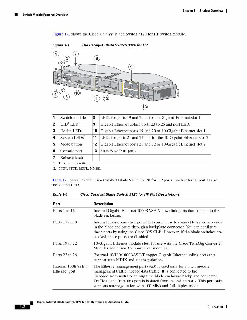
Figure 1-1 shows the Cisco Catalyst Blade Switch 3120 for HP switch module.
Figure 1-1 The Catalyst Blade Switch 3120 for HP
Table 1-1 describes the Cisco Catalyst Blade Switch 3120 for HP ports. Each external port has an associated LED.
1 Switch module 8 LEDs for ports 19 and 20 or for the Gigabit-Ethernet slot 1
2 UID1 LED
1. UID= unit identifier.
9 Gigabit Ethernet uplink ports 23 to 26 and port LEDs
3 Health LEDs 10 Gigabit Ethernet ports 19 and 20 or 10-Gigabit Ethernet slot 1
4 System LEDs2
2. SYST, STCK, MSTR, MMBR.
11 LEDs for ports 21 and 22 and for the 10-Gigabit Ethernet slot 2
5 Mode button 12 Gigabit Ethernet ports 21 and 22 or 10-Gigabit Ethernet slot 2
6 Console port 13 StackWise Plus ports
7 Release latch
2036
51
24x
SFP19-20
19-20
21-22
SYSTSTCKMSTRMMBR
CONSOLE
WS-CBS3120G-S
MODE
UID
SFP 21-22
23x
26x
STK 1
STK 2
7
4
31
2
56
9
8
10
13
11 12
Table 1-1 Cisco Catalyst Blade Switch 3120 for HP Port Descriptions
Port Description
Ports 1 to 16 Internal Gigabit Ethernet 1000BASE-X downlink ports that connect to the blade enclosure.
Ports 17 to 18 Internal cross-connection ports that you can use to connect to a second switch in the blade enclosure through a backplane connector. You can configure these ports by using the Cisco IOS CLI1. However, if the blade switches are stacked, these ports are disabled.
Ports 19 to 22 10-Gigabit Ethernet module slots for use with the Cisco TwinGig Converter Modules and Cisco X2 transceiver modules.
Ports 23 to 26 External 10/100/1000BASE-T copper Gigabit Ethernet uplink ports that support auto-MDIX and autonegotiation.
Internal 100BASE-T Ethernet port
The Ethernet management port (Fa0) is used only for switch module management traffic, not for data traffic. It is connected to the Onboard Administrator through the blade enclosure backplane connector. Traffic to and from this port is isolated from the switch ports. This port only supports autonegotiation with 100 Mb/s and full-duplex mode.
1-2Cisco Catalyst Blade Switch 3120 for HP Hardware Installation Guide
OL-12246-01
Chapter 1 Product Overview Other Features
The switch module is powered from the blade enclosure backplane, and temperature management is provided by the blade enclosure. There is no fan on the switch module.
See the software configuration guide for examples showing how you might deploy the switch module in your network.
Other FeaturesThese sections describe other switch module features:
• Switch Module Console Port, page 1-3
• 10/100/1000 Ports, page 1-3
• 10-Gigabit Ethernet Module Slots, page 1-4
• LEDs, page 1-5
• StackWise Plus Ports, page 1-8
• Power Connectors, page 1-8
Switch Module Console PortYou can connect the switch module through its console port to a PC by using the RJ-45-to-DB9 female cable that ships with the product. If you need a spare cable, you can order a kit (part number ACS-DSBUASYN=) directly from Cisco. If you want to attach the switch module to any other device, such as a terminal server, you might need a different cable. For console port and adapter pinout information, see the “Connector and Cable Specifications” section on page B-1.
10/100/1000 PortsThe 10/100/1000 Ethernet ports use standard RJ-45 connectors with Ethernet pinouts. The maximum cable length is 328 feet (100 meters). The 100BASE-TX and 1000BASE-T traffic requires Category 5, Category 5e, or Category 6 unshielded twisted pair (UTP) cable. The 10BASE-T traffic can use Category 3 or Category 4 UTP cable.
For more information about the 10/100/1000 Ethernet port connections and specifications, see the Connecting to the 10/100/1000 Ports, page 2-22, and Appendix B, “Connector and Cable Specifications.”
StackWise Plus ports Stacking cable ports.
Console port Switch module management port (RJ-45 connector).
1. CLI: command-line interface.
Table 1-1 Cisco Catalyst Blade Switch 3120 for HP Port Descriptions (continued)
Port Description
1-3Cisco Catalyst Blade Switch 3120 for HP Hardware Installation Guide
OL-12246-01
Chapter 1 Product Overview Other Features
10-Gigabit Ethernet Module Slots The 10-Gigabit Ethernet module slots are used for uplink connections to other switches and routers. The module slots operate in full-duplex mode. The CBS3120X uses the hot-swappable Cisco X2 transceiver modules and the Cisco TwinGig Converter Module. The CBS3120G uses only the Cisco TwinGig Converter Module.
These X2 transceiver modules are supported on the CBS3120X switch module:
• CX4
• LX4
• SR
• LRM
For the latest information about the supported X2 transceiver modules, see the switch release notes on Cisco.com at this location:
http://www.cisco.com/en/US/products/ps6748/tsd_products_support_series_home.html
For more information about the 10-Gigabit Ethernet module slots, see the “Installing Devices in the 10-Gigabit Ethernet Slots” section on page 2-17. For cable specifications, see Appendix B, “Connector and Cable Specifications.”
Cisco TwinGig Converter Module The Cisco TwinGig Converter Module (model CVR-X2-SFP), also known as the converter module, has two small form-factor pluggable (SFP) module slots that convert the 10-Gigabit slot into a dual SFP module interface to establish Gigabit uplinks to network devices. The SFP modules have LC connectors for fiber-optic connections or RJ-45 connectors for copper connections. These SFP modules are supported:
• 1000BASE-SX
• 1000BASE-T
For more information about the SFP modules, refer to your SFP module documentation. For the latest information about the supported SFP transceiver modules, see the switch release notes on Cisco.com at this location:
http://www.cisco.com/en/US/products/ps6748/tsd_products_support_series_home.html
For more information about the Cisco TwinGig Converter Module, see the “Installing X2 Transceiver Modules and Cisco Converter Modules” section on page 2-18. For cable specifications, see Appendix B, “Connector and Cable Specifications.”
1-4Cisco Catalyst Blade Switch 3120 for HP Hardware Installation Guide
OL-12246-01
Chapter 1 Product Overview Other Features
LEDsYou can use the switch LEDs to monitor switch module activity and performance. Graphical representations of the LEDs described in these sections are visible in the device manager.
• System LED, page 1-5
• Stack LED, page 1-5
• Stack Master LED, page 1-6
• Stack Member LED, page 1-6
• UID and Health LEDs, page 1-6
• RJ-45 Uplink Port LEDs, page 1-6
Note The System LED (SYST), stack LED (STCK), Stack Master LED (MSTR), and Stack Member LED (MMBR) are shown as item 4 in Figure 1-1 on page 1-2.
System LED
The System LED (SYST) shows whether the system is receiving power and is functioning properly. Table 1-2 lists the LED colors and their meanings.
Stack LED
To see the status of the StackWise Plus ports, press the Mode button. The Stack LED (STCK) is green when the StackWise Plus ports are up and amber when the ports are down. The bottom two 10-Gigabit Ethernet module slot LEDs show the status for StackWise Plus ports 1 and 2, respectively (see item 11 in Figure 1-1 on page 1-2).
When in stack mode, if both 10-Gigabit Ethernet uplink port LEDs are green, the stack is operating at full bandwidth. If one or both of the 10-Gigabit uplink LEDs are not green, the stack is not operating at full bandwidth.
See the “LED Behavior in Stack Mode” section on page 1-8 for more information.
Table 1-2 System LED
Color System Status
Off System is not powered on.
Blinking green POST is in progress.
Solid green System is operating normally.
Amber System is receiving power but is not functioning properly.
1-5Cisco Catalyst Blade Switch 3120 for HP Hardware Installation Guide
OL-12246-01
Chapter 1 Product Overview Other Features
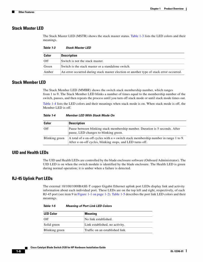
Stack Master LED
The Stack Master LED (MSTR) shows the stack master status. Table 1-3 lists the LED colors and their meanings.
Stack Member LED
The Stack Member LED (MMBR) shows the switch stack membership number, which ranges from 1 to 9. The Stack Member LED blinks a number of times equal to the membership number of the switch, pauses, and then repeats the process until you turn off stack mode or until stack mode times out.
Table 1-4 lists the LED colors and their meanings when stack mode is on. When stack mode is off, the Member LED is off.
UID and Health LEDs
The UID and Health LEDs are controlled by the blade enclosure software (Onboard Administrator). The UID LED is on when the switch module is identified by the blade enclosure. The Health LED is green during normal operation; it is amber when a failure is detected.
RJ-45 Uplink Port LEDs
The external 10/100/1000BASE-T copper Gigabit Ethernet uplink port LEDs display link and activity information about each individual port. These LEDs are on the top left and right, respectively, of each RJ-45 port (see item 9 in Figure 1-1 on page 1-2). Table 1-5 describes the port link LED colors and their meanings.
Table 1-3 Stack Master LED
Color Description
Off Switch is not the stack master.
Green Switch is the stack master or a standalone switch.
Amber An error occurred during stack master election or another type of stack error occurred.
Table 1-4 Member LED With Stack Mode On
Color Description
Off Pause between blinking stack membership number. Duration is 5 seconds. After pause, LED changes to blinking green.
Blinking green A total of n on-off cycles with n = switch stack membership number in range 1 to 9. After n on-off cycles, blinking stops, and LED turns off.
Table 1-5 Meaning of Port Link LED Colors
LED Color Meaning
Off No link established.
Solid green Link established, no activity.
Blinking green Traffic on an established link.
1-6Cisco Catalyst Blade Switch 3120 for HP Hardware Installation Guide
OL-12246-01
Chapter 1 Product Overview Other Features
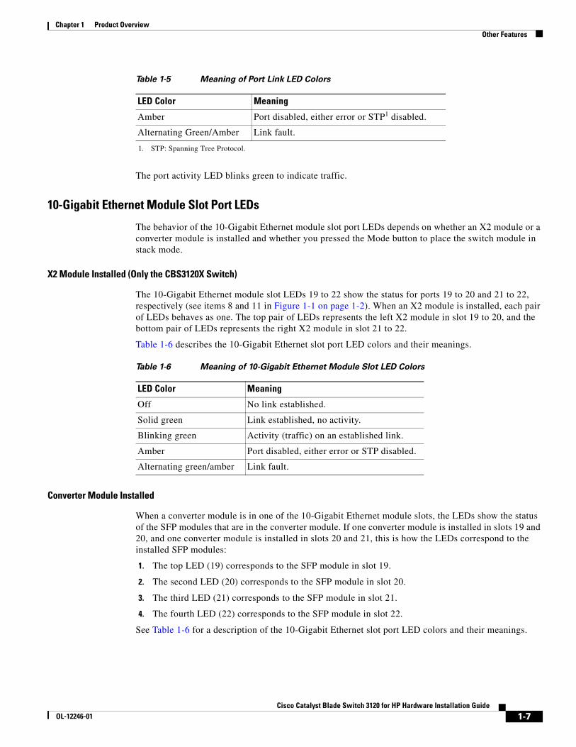
The port activity LED blinks green to indicate traffic.
10-Gigabit Ethernet Module Slot Port LEDs
The behavior of the 10-Gigabit Ethernet module slot port LEDs depends on whether an X2 module or a converter module is installed and whether you pressed the Mode button to place the switch module in stack mode.
X2 Module Installed (Only the CBS3120X Switch)
The 10-Gigabit Ethernet module slot LEDs 19 to 22 show the status for ports 19 to 20 and 21 to 22, respectively (see items 8 and 11 in Figure 1-1 on page 1-2). When an X2 module is installed, each pair of LEDs behaves as one. The top pair of LEDs represents the left X2 module in slot 19 to 20, and the bottom pair of LEDs represents the right X2 module in slot 21 to 22.
Table 1-6 describes the 10-Gigabit Ethernet slot port LED colors and their meanings.
Converter Module Installed
When a converter module is in one of the 10-Gigabit Ethernet module slots, the LEDs show the status of the SFP modules that are in the converter module. If one converter module is installed in slots 19 and 20, and one converter module is installed in slots 20 and 21, this is how the LEDs correspond to the installed SFP modules:
1. The top LED (19) corresponds to the SFP module in slot 19.
2. The second LED (20) corresponds to the SFP module in slot 20.
3. The third LED (21) corresponds to the SFP module in slot 21.
4. The fourth LED (22) corresponds to the SFP module in slot 22.
See Table 1-6 for a description of the 10-Gigabit Ethernet slot port LED colors and their meanings.
Amber Port disabled, either error or STP1 disabled.
Alternating Green/Amber Link fault.
1. STP: Spanning Tree Protocol.
Table 1-5 Meaning of Port Link LED Colors
LED Color Meaning
Table 1-6 Meaning of 10-Gigabit Ethernet Module Slot LED Colors
LED Color Meaning
Off No link established.
Solid green Link established, no activity.
Blinking green Activity (traffic) on an established link.
Amber Port disabled, either error or STP disabled.
Alternating green/amber Link fault.
1-7Cisco Catalyst Blade Switch 3120 for HP Hardware Installation Guide
OL-12246-01
Chapter 1 Product Overview Management Options
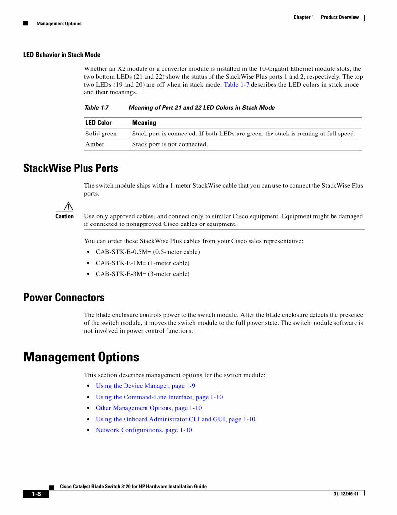
LED Behavior in Stack Mode
Whether an X2 module or a converter module is installed in the 10-Gigabit Ethernet module slots, the two bottom LEDs (21 and 22) show the status of the StackWise Plus ports 1 and 2, respectively. The top two LEDs (19 and 20) are off when in stack mode. Table 1-7 describes the LED colors in stack mode and their meanings.
StackWise Plus Ports The switch module ships with a 1-meter StackWise cable that you can use to connect the StackWise Plus ports.
Caution Use only approved cables, and connect only to similar Cisco equipment. Equipment might be damaged if connected to nonapproved Cisco cables or equipment.
You can order these StackWise Plus cables from your Cisco sales representative:
• CAB-STK-E-0.5M= (0.5-meter cable)
• CAB-STK-E-1M= (1-meter cable)
• CAB-STK-E-3M= (3-meter cable)
Power ConnectorsThe blade enclosure controls power to the switch module. After the blade enclosure detects the presence of the switch module, it moves the switch module to the full power state. The switch module software is not involved in power control functions.
Management OptionsThis section describes management options for the switch module:
• Using the Device Manager, page 1-9
• Using the Command-Line Interface, page 1-10
• Other Management Options, page 1-10
• Using the Onboard Administrator CLI and GUI, page 1-10
• Network Configurations, page 1-10
Table 1-7 Meaning of Port 21 and 22 LED Colors in Stack Mode
LED Color Meaning
Solid green Stack port is connected. If both LEDs are green, the stack is running at full speed.
Amber Stack port is not connected.
1-8Cisco Catalyst Blade Switch 3120 for HP Hardware Installation Guide
OL-12246-01
Chapter 1 Product Overview Management Options
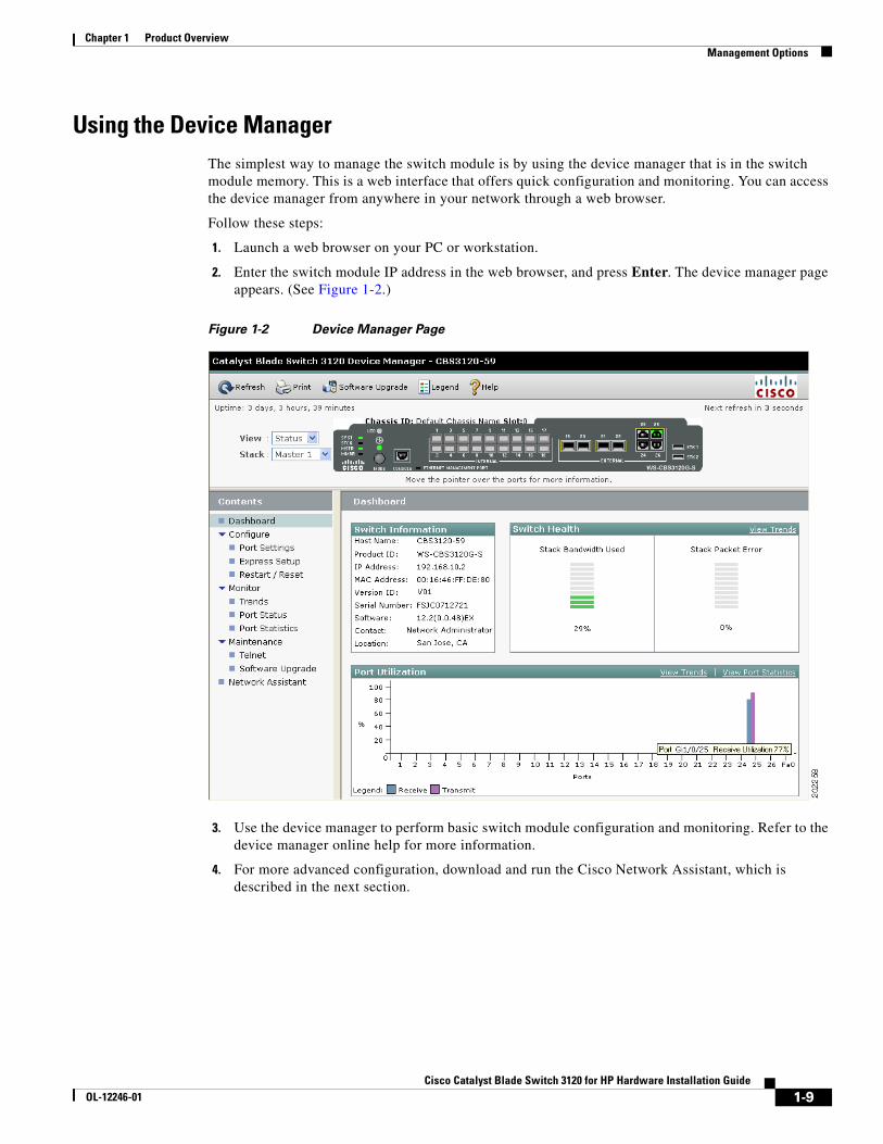
Using the Device ManagerThe simplest way to manage the switch module is by using the device manager that is in the switch module memory. This is a web interface that offers quick configuration and monitoring. You can access the device manager from anywhere in your network through a web browser.
Follow these steps:
1. Launch a web browser on your PC or workstation.
2. Enter the switch module IP address in the web browser, and press Enter. The device manager page appears. (See Figure 1-2.)
Figure 1-2 Device Manager Page
3. Use the device manager to perform basic switch module configuration and monitoring. Refer to the device manager online help for more information.
4. For more advanced configuration, download and run the Cisco Network Assistant, which is described in the next section.
1-9Cisco Catalyst Blade Switch 3120 for HP Hardware Installation Guide
OL-12246-01
Chapter 1 Product Overview Management Options
Using the Command-Line InterfaceThe switch module CLI is based on Cisco IOS software and enhanced to support desktop-switching features. You can fully configure and monitor the switch module from the CLI. You can access the CLI either by connecting your management station directly to the switch module console port or by using Telnet from a remote management station. Refer to the switch module command reference on Cisco.com for more information.
For quick setup instructions that use the CLI, go to Appendix C, “Configuring the Switch with the CLI-Based Setup Program.”
Using the Onboard Administrator CLI and GUISee the HP BladeSystem enclosure setup and installation guide at http://www.hp.com/go/bladesystem/documentation for information on how to use the Onboard Administrator CLI and GUI.
Other Management OptionsYou can use SNMP management applications such as CiscoWorks Small Network Management Solution (SNMS) to configure and manage the switch module. You also can manage it from an SNMP-compatible workstation that is running platforms such as HP OpenView or SunNet Manager.
Network ConfigurationsRefer to the switch module software configuration guide on Cisco.com for an explanation of network configuration concepts. The software configuration guide also provides examples of network configurations that use the switch module to create dedicated network segments that are interconnected through Gigabit Ethernet connections.
1-10Cisco Catalyst Blade Switch 3120 for HP Hardware Installation Guide
OL-12246-01
Cisco Catalyst BlaOL-12246-01
C H A P T E R 2
Switch InstallationThis chapter provides instructions on how to install your Cisco Catalyst Blade Switch 3120 for HP, also referred to as the switch module, in the HP c-Class BladeSystem enclosure and how to set up and configure your switch module. The HP c-Class BladeSystem, referred to as the blade enclosure, is a system that supports up to 16 server modules and up to 8 Ethernet switch modules. The switch module is installed in one of the enclosure I/O module bays on the rear panel of the server enclosure.
This chapter also describes how to interpret the power-on self-test (POST) that ensures proper operation and how to make connections to the switch module.
Read the topics and perform the procedures in this order:
• Preparing for Installation, page 2-1
• HP c-Class BladeSystem Enclosure Architecture, page 2-5
• Installing the Switch Module in the Blade Enclosure, page 2-6
• Using the Onboard Administrator to Assign an IP Address to the Switch Module and Running Express Setup, page 2-9
• Planning and Creating a Switch Stack, page 2-13
• Installing Devices in the 10-Gigabit Ethernet Slots, page 2-17
• Connecting to the 10/100/1000 Ports, page 2-22
• Planning 10/100/1000 Ethernet Port Connections, page 2-23
• Where to Go Next, page 2-24
Preparing for InstallationThis section covers these topics:
• Safety Warnings, page 2-2
• Installation Guidelines, page 2-3
• Verifying Package Contents, page 2-4
2-1de Switch 3120 for HP Hardware Installation Guide
Chapter 2 Switch Installation Preparing for Installation
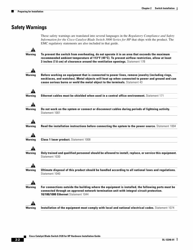
Safety WarningsThese safety warnings are translated into several languages in the Regulatory Compliance and Safety Information for the Cisco Catalyst Blade Switch 3000 Series for HP that ships with the product. The EMC regulatory statements are also included in that guide.
Warning To prevent the switch from overheating, do not operate it in an area that exceeds the maximum recommended ambient temperature of 113°F (45°C). To prevent airflow restriction, allow at least 3 inches (7.6 cm) of clearance around the ventilation openings. Statement 17B
Warning Before working on equipment that is connected to power lines, remove jewelry (including rings, necklaces, and watches). Metal objects will heat up when connected to power and ground and can cause serious burns or weld the metal object to the terminals. Statement 43
Warning Ethernet cables must be shielded when used in a central office environment. Statement 171
Warning Do not work on the system or connect or disconnect cables during periods of lightning activity. Statement 1001
Warning Read the installation instructions before connecting the system to the power source. Statement 1004
Warning Class 1 laser product. Statement 1008
Warning Only trained and qualified personnel should be allowed to install, replace, or service this equipment. Statement 1030
Warning Ultimate disposal of this product should be handled according to all national laws and regulations. Statement 1040
Warning For connections outside the building where the equipment is installed, the following ports must be connected through an approved network termination unit with integral circuit protection. 10/100/1000 Ethernet Statement 1044
Warning Installation of the equipment must comply with local and national electrical codes. Statement 1074
2-2Cisco Catalyst Blade Switch 3120 for HP Hardware Installation Guide
OL-12246-01
Chapter 2 Switch Installation Preparing for Installation
Installation GuidelinesBefore you install the switch module in the blade enclosure, read these guidelines:
• Review and become familiar with the safety and handling guidelines specified in the blade enclosure Product Information Guide.
• Review the “Safety Warnings” section on page 2-2 and the Regulatory Compliance and Safety Information for the Cisco Catalyst Blade Switch 3000 Series for HP that accompanies this guide.
Consider these prerequisites before installing your switch module:
• Fill any empty interconnect bays or any empty power module bays in the blade enclosure with blanks.
• Identify the bays in which you will insert the switch modules. Plan to install the first switch module in bay 1, the second in bay 2, and so on up to bay 8, if possible. The bay in which you choose to install each switch module depends on whether mezzanine or Ethernet cards are installed in the blade enclosure and how they are configured. See the blade enclosure documentation for more information about installing and configuring the mezzanine or Ethernet cards.
The interconnect module bays are physically interconnected in pairs through the blade enclosure backplane. That is, each of these pairs—bays 1 and 2, bays 3 and 4, bays 5 and 6, and bays 7 and 8—are interconnected. If you install two switch modules in one of the paired bays, they are internally interconnected. You must configure the switch modules to logically enable the interconnect ports, Gigabit Ethernet ports 23 and 24. See the switch module software configuration guide for information on configuring these ports.
• See the HP c-Class documentation for information on the port mapping between blade enclosures and the switch modules.
Caution To prevent electrostatic-discharge (ESD) damage when installing switch modules, follow your normal board and component handling procedures.
When you install a switch module, you do not need to power down the server modules or the enclosure.
The initial configuration assumes that the switch module was never configured, that it is in the same state as when it was received, and that it is not configured with a default username and password.
Be sure to observe these requirements:
• For copper Ethernet ports, cable lengths from the switch module to connected devices can be up to 328 feet (100 meters).
• See the documentation for the SFP module for more information about cable specifications for the SFP module connections. Also see the “SFP Module Cable Specifications” section on page B-6. Each port must match the wave-length specifications on the other end of the cable, and the cable must not exceed the stipulated cable length for reliable communications.
Note When using shorter lengths of single-mode fiber-optic cable, you might need to insert an inline optical attenuator in the link to avoid overloading the receiver.
• Operating environment is within the ranges listed in Appendix A, “Technical Specifications.”
• Cabling is away from sources of electrical noise, such as radios, power lines, and fluorescent lighting fixtures. Make sure the cabling is safely away from other devices that might damage the cables.
2-3Cisco Catalyst Blade Switch 3120 for HP Hardware Installation Guide
OL-12246-01
Chapter 2 Switch Installation Preparing for Installation
Verifying Package ContentsCarefully remove the contents from the shipping container, and look at each item for damage. If any item is missing or damaged, contact your Cisco representative or reseller for support. Return all packing material to the shipping container, and save it.
These items ship with your switch module. The Cisco TwinGig Converter Modules with installed protective dust covers are shipped already installed on your switch module.
• Console cable
• 1-meter Stackwise Plus cable
• Documentation CD that contains:
– Cisco Catalyst Blade Switch 3000 Series for HP Getting Started Guide
– Regulatory Compliance and Safety Information for the Cisco Catalyst Blade Switch 3000 Series for HP
– Cisco and HP Warranty Information
Note If the switch modules are ordered with the blade enclosure, the switch modules are already installed, and no unpacking is required. The unpacking procedure applies only if a switch module is ordered separately.
2-4Cisco Catalyst Blade Switch 3120 for HP Hardware Installation Guide
OL-12246-01
Chapter 2 Switch Installation HP c-Class BladeSystem Enclosure Architecture
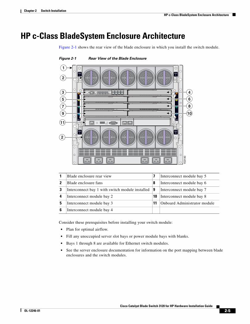
HP c-Class BladeSystem Enclosure ArchitectureFigure 2-1 shows the rear view of the blade enclosure in which you install the switch module.
Figure 2-1 Rear View of the Blade Enclosure
Consider these prerequisites before installing your switch module:
• Plan for optimal airflow.
• Fill any unoccupied server slot bays or power module bays with blanks.
• Bays 1 through 8 are available for Ethernet switch modules.
• See the server enclosure documentation for information on the port mapping between blade enclosures and the switch modules.
1 Blade enclosure rear view 7 Interconnect module bay 5
2 Blade enclosure fans 8 Interconnect module bay 6
3 Interconnect bay 1 with switch module installed 9 Interconnect module bay 7
4 Interconnect module bay 2 10 Interconnect module bay 8
5 Interconnect module bay 3 11 Onboard Administrator module
6 Interconnect module bay 4
1531
40
1
3
5
7
9
11
2
2
4
6
8
10
2-5Cisco Catalyst Blade Switch 3120 for HP Hardware Installation Guide
OL-12246-01
Chapter 2 Switch Installation Installing the Switch Module in the Blade Enclosure
Installing the Switch Module in the Blade EnclosureBefore you install the switch module in the blade enclosure, consider these points:
• Review and become familiar with the safety guidelines in the Regulatory Compliance and Safety Information for the Cisco Catalyst Blade Switch 3000 Series for HP that accompanies this guide.
• Review and become familiar with the safety guidelines in the HP BladeSystem enclosure setup and installation guide.
• Review and become familiar with the temperature, power, and grounding requirements specified in the HP BladeSystem enclosure setup and installation guide.
Warning Only trained and qualified personnel should be allowed to install, replace, or service this equipment. Statement 1030
Caution To prevent electrostatic-discharge (ESD) damage when installing switch modules, follow your normal board and component handling procedures.
When you install a switch module, you do not need to power down the blade enclosure.
Follow these steps to install the switch module in the blade enclosure:
Step 1 If you have not already done so, touch the static-protective package that contains the switch module to an unpainted metal part of the blade enclosure for at least 2 seconds.
Step 2 Remove the switch module from its static-protective package.
Step 3 Remove the interconnect blank from the bay where you plan to install the switch module, if one is present, and install the switch module. (See Figure 2-2.)
2-6Cisco Catalyst Blade Switch 3120 for HP Hardware Installation Guide
OL-12246-01
Chapter 2 Switch Installation Installing the Switch Module in the Blade Enclosure
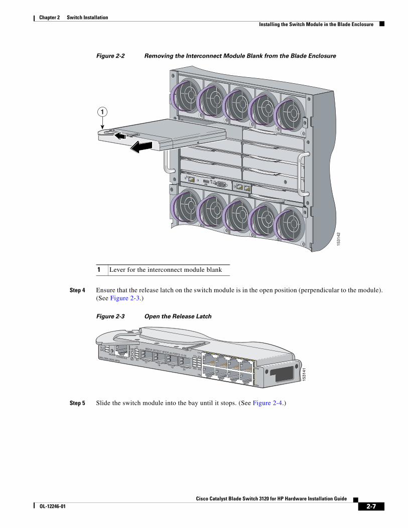
Figure 2-2 Removing the Interconnect Module Blank from the Blade Enclosure
Step 4 Ensure that the release latch on the switch module is in the open position (perpendicular to the module). (See Figure 2-3.)
Figure 2-3 Open the Release Latch
Step 5 Slide the switch module into the bay until it stops. (See Figure 2-4.)
1 Lever for the interconnect module blank
1531
42
1
1531
41
23x
24x
21x
24x
17x
18x
17x
20x
17
20
SYSTSTAT
DLXSPD
CONSOLE
UID
WS-CBS-3020-HPQ
MODE
MEDIA DETECT SFP/R-45 PORTS 17-20
17
20
1819
2-7Cisco Catalyst Blade Switch 3120 for HP Hardware Installation Guide
OL-12246-01
Chapter 2 Switch Installation Installing the Switch Module in the Blade Enclosure
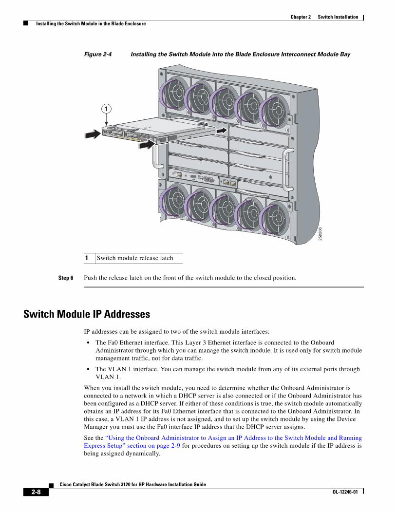
Figure 2-4 Installing the Switch Module into the Blade Enclosure Interconnect Module Bay
Step 6 Push the release latch on the front of the switch module to the closed position.
Switch Module IP AddressesIP addresses can be assigned to two of the switch module interfaces:
• The Fa0 Ethernet interface. This Layer 3 Ethernet interface is connected to the Onboard Administrator through which you can manage the switch module. It is used only for switch module management traffic, not for data traffic.
• The VLAN 1 interface. You can manage the switch module from any of its external ports through VLAN 1.
When you install the switch module, you need to determine whether the Onboard Administrator is connected to a network in which a DHCP server is also connected or if the Onboard Administrator has been configured as a DHCP server. If either of these conditions is true, the switch module automatically obtains an IP address for its Fa0 Ethernet interface that is connected to the Onboard Administrator. In this case, a VLAN 1 IP address is not assigned, and to set up the switch module by using the Device Manager you must use the Fa0 interface IP address that the DHCP server assigns.
See the “Using the Onboard Administrator to Assign an IP Address to the Switch Module and Running Express Setup” section on page 2-9 for procedures on setting up the switch module if the IP address is being assigned dynamically.
1 Switch module release latch
2503
06
24x
SFP19-20
19-20
21-22
SYSTS-MODES-MSTRS-MMBR
CONSOLE
WS-CBS3120G-S
MODE
UID
SFP 21-22
23x
26x
STK A
STK B
24x
1
2-8Cisco Catalyst Blade Switch 3120 for HP Hardware Installation Guide
OL-12246-01
Chapter 2 Switch Installation Using the Onboard Administrator to Assign an IP Address to the Switch Module and Running Express Setup
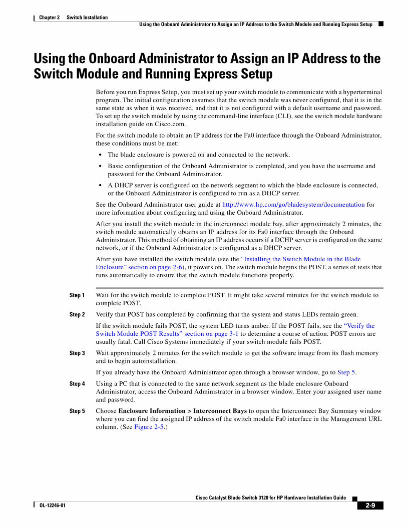
Using the Onboard Administrator to Assign an IP Address to the Switch Module and Running Express Setup
Before you run Express Setup, you must set up your switch module to communicate with a hyperterminal program. The initial configuration assumes that the switch module was never configured, that it is in the same state as when it was received, and that it is not configured with a default username and password. To set up the switch module by using the command-line interface (CLI), see the switch module hardware installation guide on Cisco.com.
For the switch module to obtain an IP address for the Fa0 interface through the Onboard Administrator, these conditions must be met:
• The blade enclosure is powered on and connected to the network.
• Basic configuration of the Onboard Administrator is completed, and you have the username and password for the Onboard Administrator.
• A DHCP server is configured on the network segment to which the blade enclosure is connected, or the Onboard Administrator is configured to run as a DHCP server.
See the Onboard Administrator user guide at http://www.hp.com/go/bladesystem/documentation for more information about configuring and using the Onboard Administrator.
After you install the switch module in the interconnect module bay, after approximately 2 minutes, the switch module automatically obtains an IP address for its Fa0 interface through the Onboard Administrator. This method of obtaining an IP address occurs if a DCHP server is configured on the same network, or if the Onboard Administrator is configured as a DHCP server.
After you have installed the switch module (see the “Installing the Switch Module in the Blade Enclosure” section on page 2-6), it powers on. The switch module begins the POST, a series of tests that runs automatically to ensure that the switch module functions properly.
Step 1 Wait for the switch module to complete POST. It might take several minutes for the switch module to complete POST.
Step 2 Verify that POST has completed by confirming that the system and status LEDs remain green.
If the switch module fails POST, the system LED turns amber. If the POST fails, see the “Verify the Switch Module POST Results” section on page 3-1 to determine a course of action. POST errors are usually fatal. Call Cisco Systems immediately if your switch module fails POST.
Step 3 Wait approximately 2 minutes for the switch module to get the software image from its flash memory and to begin autoinstallation.
If you already have the Onboard Administrator open through a browser window, go to Step 5.
Step 4 Using a PC that is connected to the same network segment as the blade enclosure Onboard Administrator, access the Onboard Administrator in a browser window. Enter your assigned user name and password.
Step 5 Choose Enclosure Information > Interconnect Bays to open the Interconnect Bay Summary window where you can find the assigned IP address of the switch module Fa0 interface in the Management URL column. (See Figure 2-5.)
2-9Cisco Catalyst Blade Switch 3120 for HP Hardware Installation Guide
OL-12246-01
Chapter 2 Switch Installation Using the Onboard Administrator to Assign an IP Address to the Switch Module and Running Express Setup
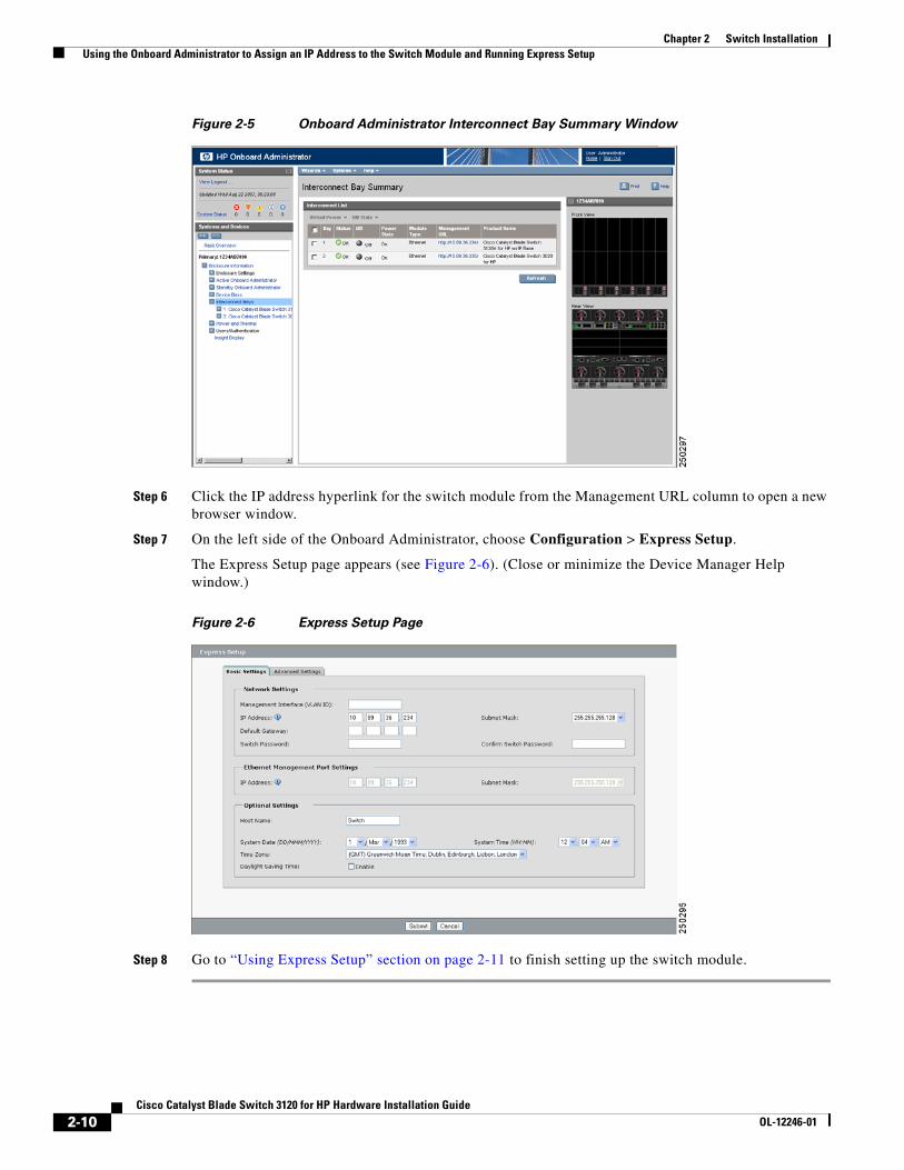
Figure 2-5 Onboard Administrator Interconnect Bay Summary Window
Step 6 Click the IP address hyperlink for the switch module from the Management URL column to open a new browser window.
Step 7 On the left side of the Onboard Administrator, choose Configuration > Express Setup.
The Express Setup page appears (see Figure 2-6). (Close or minimize the Device Manager Help window.)
Figure 2-6 Express Setup Page
Step 8 Go to “Using Express Setup” section on page 2-11 to finish setting up the switch module.
2-10Cisco Catalyst Blade Switch 3120 for HP Hardware Installation Guide
OL-12246-01
Chapter 2 Switch Installation Using the Onboard Administrator to Assign an IP Address to the Switch Module and Running Express Setup
Using Express SetupBefore you complete the setup program, obtain the default gateway IP address and the switch password from your system administrator. You can use Express Setup to configure these optional parameters through the Express Setup program:
• Telnet access password
• Names of the SNMP read and write community strings if you are going to use a network-management program like CiscoWorks.
• Host name, system contact, and system location
• System time, time zone, Daylight Savings Time enable
Follow these steps to finish setting up the switch module. The Onboard Administrator assigns an IP address and a subnet mask to the management interface (VLAN ID) and to the Ethernet management port.
Step 1 Enter this information in the Network Settings fields.
• In the Default Gateway field, enter the IP address for the default gateway (router).
• In the Switch Password field, enter your password. The password can be from 1 to 25 alphanumeric characters, can start with a number, is case sensitive, allows embedded spaces, but does not allow spaces at the beginning or end. In the Confirm Switch Password field, enter your password again.
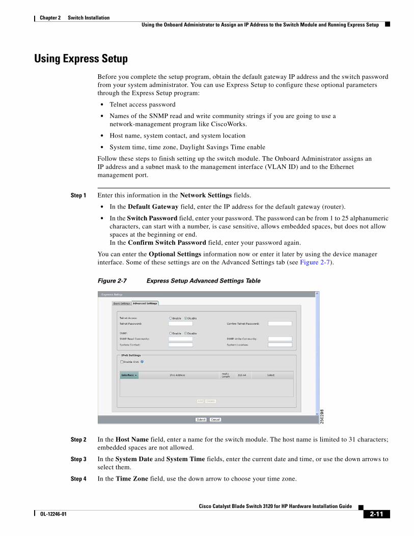
You can enter the Optional Settings information now or enter it later by using the device manager interface. Some of these settings are on the Advanced Settings tab (see Figure 2-7).
Figure 2-7 Express Setup Advanced Settings Table
Step 2 In the Host Name field, enter a name for the switch module. The host name is limited to 31 characters; embedded spaces are not allowed.
Step 3 In the System Date and System Time fields, enter the current date and time, or use the down arrows to select them.
Step 4 In the Time Zone field, use the down arrow to choose your time zone.
2-11Cisco Catalyst Blade Switch 3120 for HP Hardware Installation Guide
OL-12246-01
Chapter 2 Switch Installation Using the Onboard Administrator to Assign an IP Address to the Switch Module and Running Express Setup
Step 5 Click Enable in the Daylight Savings Time field to enable this feature.
Step 6 In the Telnet Access field, click Enable if you are going to use Telnet to manage the switch module by using the CLI. If you enable Telnet access, you must enter a Telnet password.
Note If you plan to create a switch stack, enable Telnet access so that you can use the CLI to set this switch to the highest priority. See the “Planning and Creating a Switch Stack” section on page 2-13 for more information about creating a switch stack.
Step 7 In the Telnet Password field, enter a password. The Telnet password can be from 1 to 25 alphanumeric characters, is case sensitive, allows embedded spaces, but does not allow spaces at the beginning or end. In the Confirm Telnet Password field, re-enter the Telnet password.
Step 8 In the SNMP field, click Enable to enable Simple Network Management Protocol (SNMP). Enable SNMP only if you plan to manage switches by using CiscoWorks 2000 or another SNMP-based network-management system.
Step 9 If you enable SNMP, you must enter a community string in the SNMP Read Community field, the SNMP Write Community field, or both. SNMP community strings authenticate access to MIB objects. Embedded spaces are not allowed in SNMP community strings. When you set the SNMP read community, you can access SNMP information, but you cannot modify it. When you set the SNMP write community, you can both access and modify SNMP information.
Step 10 In the System Contact field, enter the name of the person who is responsible for the switch module. In the System Location field, enter the wiring closet, floor, or building where the switch module is located.
Step 11 Click Submit to save your settings, or click Cancel to clear your settings.
You can close this window.
To install additional switch modules, repeat the steps in the “Installing the Switch Module in the Blade Enclosure” section on page 2-6 through the “Using the Onboard Administrator to Assign an IP Address to the Switch Module and Running Express Setup” section on page 2-9.
Setting the Installed Switch Module As the Stack Master If you plan to create a switch stack, we recommend that you set the switch module that you first configured as the stack master. To do this, you must assign the highest priority value to this switch module. To assign a priority value after you have installed and initially configured the first switch module, follow these steps:
Step 1 Launch a Telnet session by connecting directly to the switch through its console port, or by using the Onboard Administrator:
On the left side of the Onboard Administrator, click + next to Interconnect Bays to expand it, then click + next to the name of the switch you want to set as the switch master. Click Management Console to open the device manager for the switch, and if prompted, enter the user name and password for the switch. Under Contents, choose Maintenance > Telnet.
Step 2 Enter enable.
Step 3 Enter configure terminal.
Step 4 Enter switch 1 priority 15.
2-12Cisco Catalyst Blade Switch 3120 for HP Hardware Installation Guide
OL-12246-01
Chapter 2 Switch Installation Planning and Creating a Switch Stack
Step 5 At the prompt, press Return.
Step 6 Enter end.
Step 7 Enter copy running-configuration startup-configuration to save this setting.
Step 8 At the prompt, press Return.
Step 9 To verify that this switch is set as the switch master, enter the show switch user EXEC command.
For more information about creating switch stacks, see the “Planning and Creating a Switch Stack” section on page 2-13.
Refreshing the PC IP AddressAfter you complete Express Setup, you should refresh the PC IP address:
• For a dynamically assigned IP address, disconnect the PC from the switch module, and reconnect the PC to the network. The network DHCP server assigns a new IP address to the PC.
• For a statically assigned IP address, change it to the previously configured IP address.
Planning and Creating a Switch Stack A switch stack is a set of up to nine stacking-capable switch modules that are connected through their StackWise Plus ports. One of the switches controls the operation of the stack and is called the stack master. The stack master and the other switches in the stack are stack members. Layer 2 and Layer 3 protocols present the entire switch stack as a single entity to the network. Stacking is optional.
When switch modules are not stacked, each acts as a standalone switch. For general concepts and procedures to manage switch stacks, see the switch module software configuration guide and command reference on Cisco.com.
Caution The Cisco Catalyst Blade Switch 3120 for HP does not support switch stacks with other types of blade switches as members. Combining the Cisco Catalyst Blade Switch 3120 for HP with other types of blade switches in a switch stack might cause the switch to work improperly or to fail.
Before you connect the switch modules in a stack, keep in mind these stacking guidelines:
• You should install the stack master switch module and run the initial setup program on that switch module before you connect the StackWise Plus cables to other stack members. We recommend that you assign the highest priority value to the switch module that you prefer to be the stack master. This ensures that the switch is re-elected as stack master if a re-election occurs. As you add new switch modules to the stack, they automatically become stack members.
To assign a priority value through the Onboard Administrator after you have installed and initially configured the first switch module, see the “Setting the Installed Switch Module As the Stack Master” section on page 2-12.
• When you connect the StackWise Plus cables and create a stack, you can communicate with the master switch internal Ethernet management port (Fa0) port, but not the Fa0 ports of the member switches. Only one Fa0 interface can be active, and that interface is the one on the active stack master.
2-13Cisco Catalyst Blade Switch 3120 for HP Hardware Installation Guide
OL-12246-01
Chapter 2 Switch Installation Planning and Creating a Switch Stack
• For conditions that might cause a stack master re-election or to manually elect the stack master, see the “Managing Switch Stacks” chapter in the switch module software configuration guide on Cisco.com.
• You can stack any combination of up to nine Catalyst 3120G and 3120X switches. You can stack only the Cisco Catalyst Blade Switch 3120 for HP switch modules; other switches are not supported.
• Before installation, verify the StackWise Plus cable length. Depending on your configuration, you might need different sized cables. The 1-meter cable is suppled if you do not specify the length of the StackWise Plus cable when you order your product. If you need the 0.5-meter cable or the 3-meter cable, you can order these StackWise Plus cables from your Cisco sales representative:
– CAB-STK-E-0.5M= (0.5-meter cable)
– CAB-STK-E-1M= (1-meter cable)
– CAB-STK-E-3M= (3-meter cable)
For switch module dimensions, StackWise Plus cable part numbers, and additional stacking guidelines, see the switch module hardware installation guide on Cisco.com. For concepts and procedures to manage switch stacks, see the switch module software configuration guide and the stack compatibility guide also on Cisco.com.
To create a switch stack:
• Install the member switch modules if you have not already done so.
• Connect the StackWise Plus cables as described in the “Planning and Creating a Switch Stack” section on page 2-13.
• Configure the member switch modules through the master switch by using the CLI.
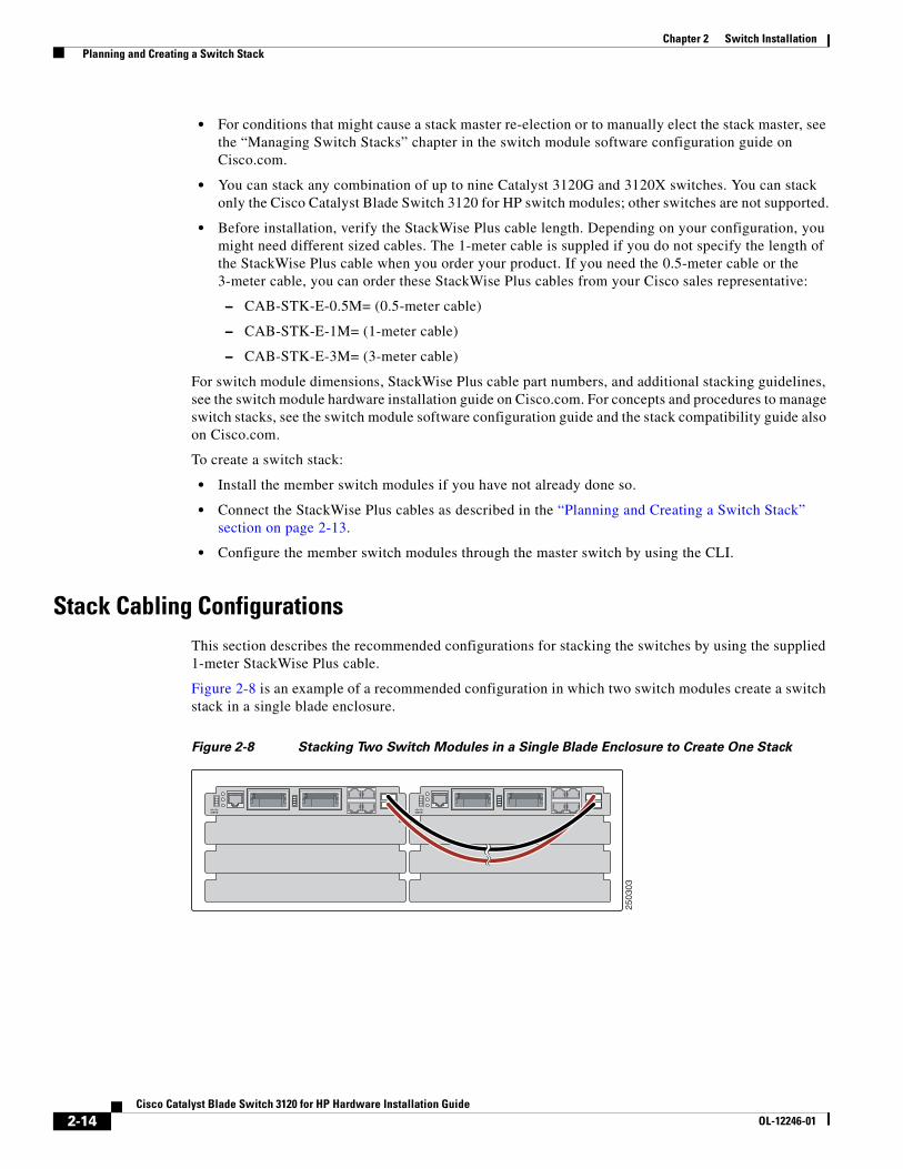
Stack Cabling ConfigurationsThis section describes the recommended configurations for stacking the switches by using the supplied 1-meter StackWise Plus cable.
Figure 2-8 is an example of a recommended configuration in which two switch modules create a switch stack in a single blade enclosure.
Figure 2-8 Stacking Two Switch Modules in a Single Blade Enclosure to Create One Stack
2503
03
2-14Cisco Catalyst Blade Switch 3120 for HP Hardware Installation Guide
OL-12246-01
Chapter 2 Switch Installation Planning and Creating a Switch Stack
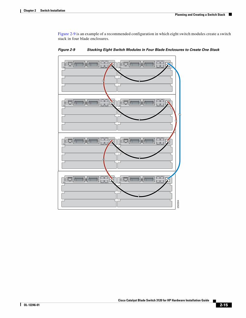
Figure 2-9 is an example of a recommended configuration in which eight switch modules create a switch stack in four blade enclosures.
Figure 2-9 Stacking Eight Switch Modules in Four Blade Enclosures to Create One Stack
2503
04
2-15Cisco Catalyst Blade Switch 3120 for HP Hardware Installation Guide
OL-12246-01
Chapter 2 Switch Installation Planning and Creating a Switch Stack
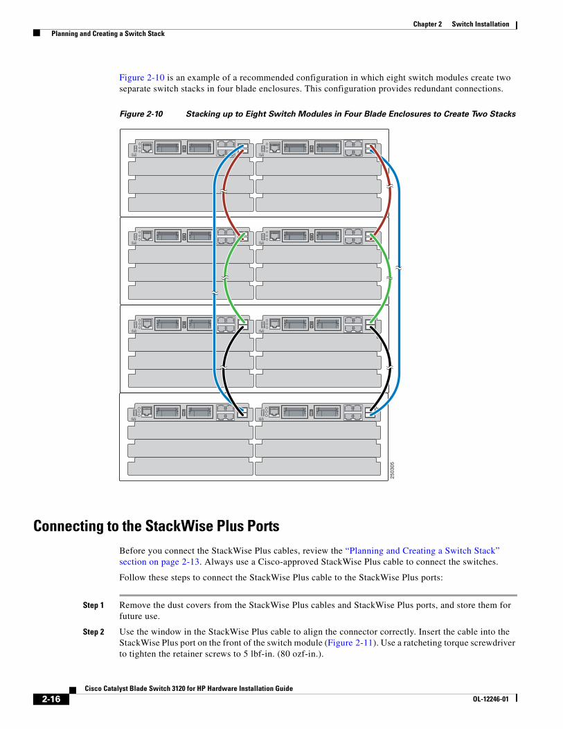
Figure 2-10 is an example of a recommended configuration in which eight switch modules create two separate switch stacks in four blade enclosures. This configuration provides redundant connections.
Figure 2-10 Stacking up to Eight Switch Modules in Four Blade Enclosures to Create Two Stacks
Connecting to the StackWise Plus Ports Before you connect the StackWise Plus cables, review the “Planning and Creating a Switch Stack” section on page 2-13. Always use a Cisco-approved StackWise Plus cable to connect the switches.
Follow these steps to connect the StackWise Plus cable to the StackWise Plus ports:
Step 1 Remove the dust covers from the StackWise Plus cables and StackWise Plus ports, and store them for future use.
Step 2 Use the window in the StackWise Plus cable to align the connector correctly. Insert the cable into the StackWise Plus port on the front of the switch module (Figure 2-11). Use a ratcheting torque screwdriver to tighten the retainer screws to 5 lbf-in. (80 ozf-in.).
2503
05
2-16Cisco Catalyst Blade Switch 3120 for HP Hardware Installation Guide
OL-12246-01
Chapter 2 Switch Installation Installing Devices in the 10-Gigabit Ethernet Slots
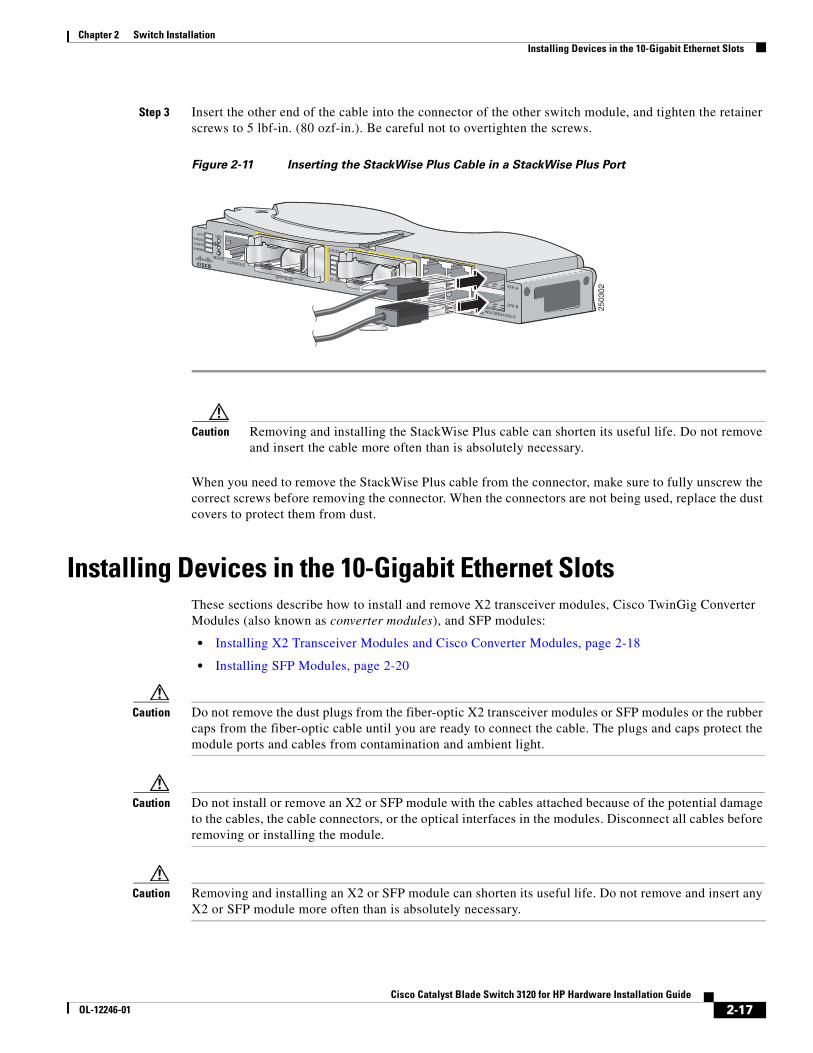
Step 3 Insert the other end of the cable into the connector of the other switch module, and tighten the retainer screws to 5 lbf-in. (80 ozf-in.). Be careful not to overtighten the screws.
Figure 2-11 Inserting the StackWise Plus Cable in a StackWise Plus Port
Caution Removing and installing the StackWise Plus cable can shorten its useful life. Do not remove and insert the cable more often than is absolutely necessary.
When you need to remove the StackWise Plus cable from the connector, make sure to fully unscrew the correct screws before removing the connector. When the connectors are not being used, replace the dust covers to protect them from dust.
Installing Devices in the 10-Gigabit Ethernet Slots These sections describe how to install and remove X2 transceiver modules, Cisco TwinGig Converter Modules (also known as converter modules), and SFP modules:
• Installing X2 Transceiver Modules and Cisco Converter Modules, page 2-18
• Installing SFP Modules, page 2-20
Caution Do not remove the dust plugs from the fiber-optic X2 transceiver modules or SFP modules or the rubber caps from the fiber-optic cable until you are ready to connect the cable. The plugs and caps protect the module ports and cables from contamination and ambient light.
Caution Do not install or remove an X2 or SFP module with the cables attached because of the potential damage to the cables, the cable connectors, or the optical interfaces in the modules. Disconnect all cables before removing or installing the module.
Caution Removing and installing an X2 or SFP module can shorten its useful life. Do not remove and insert any X2 or SFP module more often than is absolutely necessary.
2503
02
24x
SFP19-20
19-20
21-22
SYSTS-MODES-MSTRS-MMBR
CONSOLE
WS-CBS3120G-S
MODE
UID
SFP 21-22
23x
26x
STK A
STK B
2-17Cisco Catalyst Blade Switch 3120 for HP Hardware Installation Guide
OL-12246-01
Chapter 2 Switch Installation Installing Devices in the 10-Gigabit Ethernet Slots
Caution To prevent ESD damage, follow your normal board and component handling procedures when connecting cables to the switch and other devices.
Installing X2 Transceiver Modules and Cisco Converter ModulesThese sections describe how to install and remove X2 transceiver modules and the converter modules in the switch module 10-Gigabit Ethernet module slots.
Note Do not remove the dust cover from the converter module until you are ready to install an X2 transceiver or SFP modules. A module or dust cover must be installed in the slot at all times.
Use only Cisco X2 transceiver modules and Cisco TwinGig Converter Modules with the switch module. Each Cisco transceiver and converter module has an internal serial EEPROM that is encoded with security information. This encoding provides a way for Cisco to identify and validate that the module meets the requirements for the switch.
For more information about installing, removing, cabling, and troubleshooting X2 transceiver modules, see the module documentation that shipped with your device. For module cable specifications, see Appendix B, “Connector and Cable Specifications.”
Installing a Transceiver or Converter Module
When you install or remove the converter module, the mode on the switch changes from 10-Gigabit Ethernet to Gigabit Ethernet or the reverse. During this mode change, data traffic on the other switch module uplink ports (X2 transceiver or SFP module ports) might temporarily stop. When you install or remove an X2 transceiver or SFP module, traffic delay does not occur.
To insert an X2 transceiver module or a converter module, follow these steps:
Step 1 Attach an ESD-preventive wrist strap to your wrist and to a bare metal surface.
Step 2 Remove the transceiver or converter module from its protective packaging.
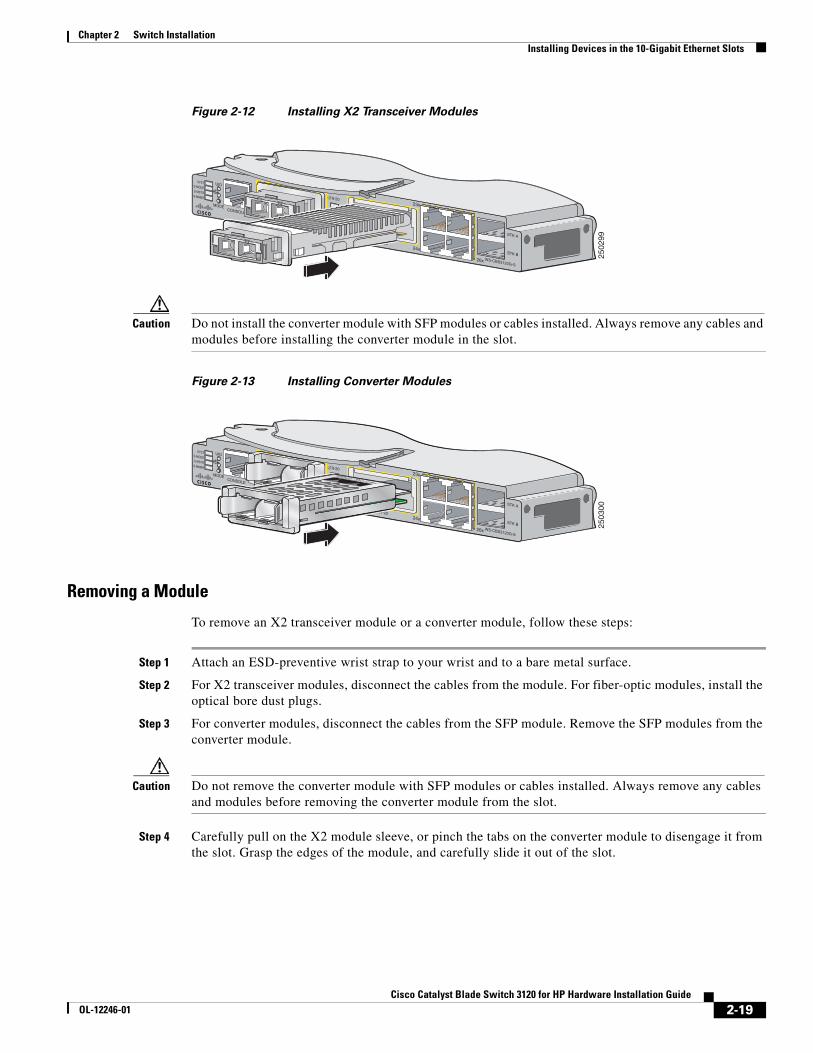
Step 3 Align the transceiver module in the module slot (Figure 2-12 and Figure 2-13).
Caution Verify the correct orientation of your module before inserting it into the slot. Incorrect insertion can damage the module.
Step 4 Slide the transceiver or converter module into the opening until the back of its faceplate is flush with the switch module faceplate.
2-18Cisco Catalyst Blade Switch 3120 for HP Hardware Installation Guide
OL-12246-01
Chapter 2 Switch Installation Installing Devices in the 10-Gigabit Ethernet Slots
Figure 2-12 Installing X2 Transceiver Modules
Caution Do not install the converter module with SFP modules or cables installed. Always remove any cables and modules before installing the converter module in the slot.
Figure 2-13 Installing Converter Modules
Removing a Module
To remove an X2 transceiver module or a converter module, follow these steps:
Step 1 Attach an ESD-preventive wrist strap to your wrist and to a bare metal surface.
Step 2 For X2 transceiver modules, disconnect the cables from the module. For fiber-optic modules, install the optical bore dust plugs.
Step 3 For converter modules, disconnect the cables from the SFP module. Remove the SFP modules from the converter module.
Caution Do not remove the converter module with SFP modules or cables installed. Always remove any cables and modules before removing the converter module from the slot.
Step 4 Carefully pull on the X2 module sleeve, or pinch the tabs on the converter module to disengage it from the slot. Grasp the edges of the module, and carefully slide it out of the slot.
2502
99
24x
SFP19-20
19-20
21-22
SYSTS-MODES-MSTRS-MMBR
CONSOLE
WS-CBS3120G-S
MODE
UID
SFP 21-22
23x
26x
STK A
STK B
2503
00
24x
SFP19-20
19-20
21-22
SYSTS-MODES-MSTRS-MMBR
CONSOLE
WS-CBS3120G-S
MODE
UID
SFP 21-22
23x
26x
STK A
STK B
2-19Cisco Catalyst Blade Switch 3120 for HP Hardware Installation Guide
OL-12246-01
Chapter 2 Switch Installation Installing Devices in the 10-Gigabit Ethernet Slots
Step 5 Reinstall the dust cover in the 10-Gigabit Ethernet slot.
Caution The dust covers should always remain in place unless a module is installed in the slot.
Step 6 Place the module in an antistatic bag or other protective environment.
Installing SFP ModulesThis section describes how to install and remove SFP modules in the 10-Gigabit Ethernet slots. To use SFP modules in the switch, you must have a converter module installed in a 10-Gigabit Ethernet slot.
Caution To avoid damage to the converter module, first install the converter module in the switch 10-Gigabit Ethernet slot before installing the SFP modules.
See the switch module release notes on Cisco.com for the list of SFP modules that the switch module supports. Use only Cisco SFP modules on the switch. Each Cisco module has an internal serial EEPROM that is encoded with security information. This encoding provides a way for Cisco to identify and validate that the SFP module meets the requirements for the switch.
For more information about installing, removing, cabling, and troubleshooting SFP modules, see the module documentation that shipped with your device. For module cable specifications, see Appendix B, “Connector and Cable Specifications.”
Installing an SFP Module
To insert an SFP module into a converter module slot, follow these steps:
Step 1 Attach an ESD-preventive wrist strap to your wrist and to a bare metal surface.
Step 2 Remove the Cisco TwinGig Converter Module dust cover and save.
Note The dust cover is an integral part of the airflow function. If you remove the SFP module, you must replace it with the saved dust cover.
Step 3 Install the converter module in the 10-Gigabit Ethernet module slot as described in “Installing a Transceiver or Converter Module” section on page 2-18.
Step 4 Find the send (TX) and receive (RX) markings that identify the top side of the SFP module.
On some SFP modules, the send and receive (TX and RX) markings might be replaced by arrows that show the direction of the connection, either send or receive (TX or RX).
Step 5 If the SFP module has a bale-clasp latch, move it to the open, unlocked position.
Step 6 Align the SFP module in the converter module opening. When installing a module in the upper module slot (slot 1), position the SFP module face up. When using the lower module slot (slot 2), position the SFP module face down.
Step 7 Slide the SFP module into the opening until you feel the connector on the module snap into place (Figure 2-14).
2-20Cisco Catalyst Blade Switch 3120 for HP Hardware Installation Guide
OL-12246-01
Chapter 2 Switch Installation Installing Devices in the 10-Gigabit Ethernet Slots
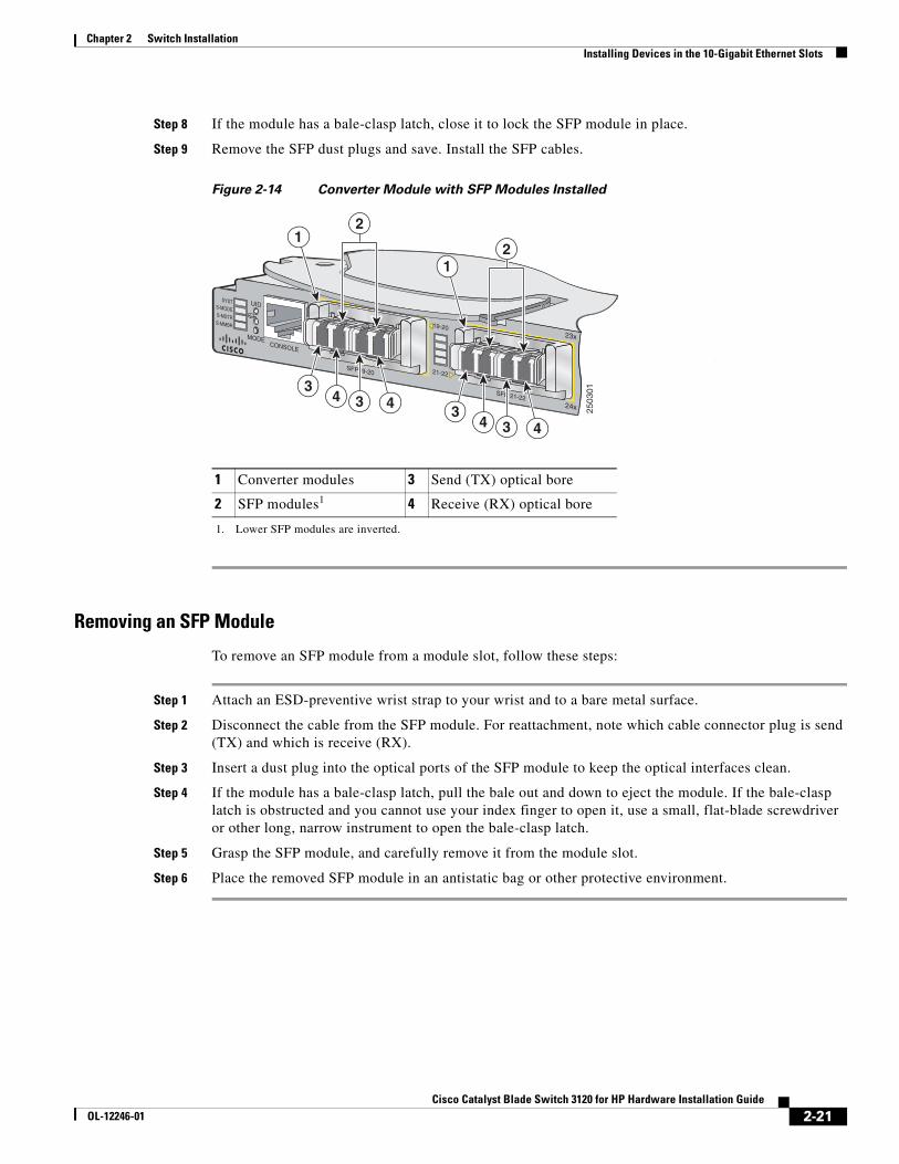
Step 8 If the module has a bale-clasp latch, close it to lock the SFP module in place.
Step 9 Remove the SFP dust plugs and save. Install the SFP cables.
Figure 2-14 Converter Module with SFP Modules Installed
Removing an SFP Module
To remove an SFP module from a module slot, follow these steps:
Step 1 Attach an ESD-preventive wrist strap to your wrist and to a bare metal surface.
Step 2 Disconnect the cable from the SFP module. For reattachment, note which cable connector plug is send (TX) and which is receive (RX).
Step 3 Insert a dust plug into the optical ports of the SFP module to keep the optical interfaces clean.
Step 4 If the module has a bale-clasp latch, pull the bale out and down to eject the module. If the bale-clasp latch is obstructed and you cannot use your index finger to open it, use a small, flat-blade screwdriver or other long, narrow instrument to open the bale-clasp latch.
Step 5 Grasp the SFP module, and carefully remove it from the module slot.
Step 6 Place the removed SFP module in an antistatic bag or other protective environment.
1 Converter modules 3 Send (TX) optical bore
2 SFP modules1
1. Lower SFP modules are inverted.
4 Receive (RX) optical bore
2503
01
24x
SFP19-20
19-20
21-22
SYSTS-MODES-MSTRS-MMBR
CONSOLE
MODE
UID
SFP 21-22
23x
3
21
4 43
3
21
4 43
2-21Cisco Catalyst Blade Switch 3120 for HP Hardware Installation Guide
OL-12246-01
Chapter 2 Switch Installation Connecting to the 10/100/1000 Ports
Connecting to the 10/100/1000 PortsThe switch module 10/100/1000 ports configure themselves to operate at the speed of attached devices. If the attached ports do not support autonegotiation, you can explicitly set the speed and duplex parameters. Connecting devices that do not autonegotiate or that have their speed and duplex parameters manually set can reduce performance or result in no linkage.
To maximize performance, choose one of these methods for configuring the Ethernet ports:
• Let the ports autonegotiate both speed and duplex.
• Set the port speed and duplex parameters on both ends of the connection.
Follow these steps to connect to 10BASE-T, 100BASE-TX or 1000BASE-T devices:
Caution To prevent electrostatic-discharge (ESD) damage, follow your normal board and component handling procedures.
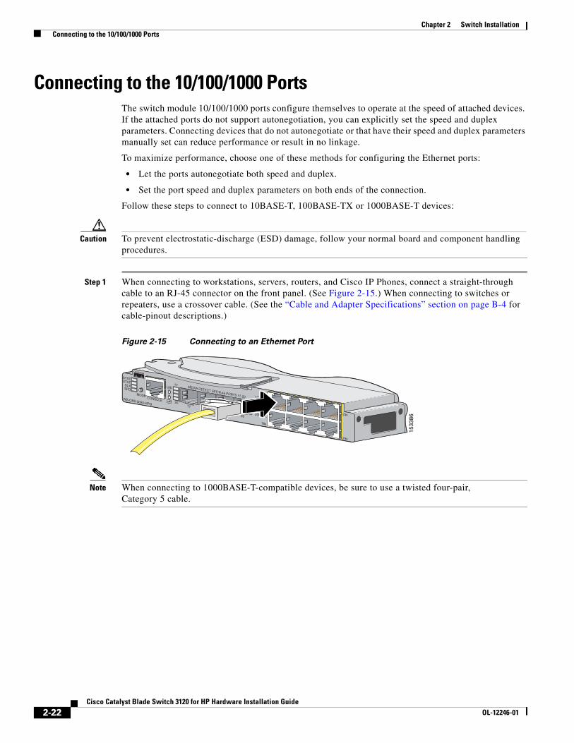
Step 1 When connecting to workstations, servers, routers, and Cisco IP Phones, connect a straight-through cable to an RJ-45 connector on the front panel. (See Figure 2-15.) When connecting to switches or repeaters, use a crossover cable. (See the “Cable and Adapter Specifications” section on page B-4 for cable-pinout descriptions.)
Figure 2-15 Connecting to an Ethernet Port
Note When connecting to 1000BASE-T-compatible devices, be sure to use a twisted four-pair, Category 5 cable.
1533
8623x
24x
21x
24x
17x
18x
17x
20x
17
20
SYSTSTAT
DLXSPD
CONSOLE
UID
WS-CBS-3020-HPQ
MODE
MEDIA DETECT SFP/R-45 PORTS 17-20
17
20
1819
2-22Cisco Catalyst Blade Switch 3120 for HP Hardware Installation Guide
OL-12246-01
Chapter 2 Switch Installation Planning 10/100/1000 Ethernet Port Connections
Note You can use the mdix auto interface configuration command in the CLI to enable the automatic medium-dependent interface crossover (auto-MDIX) feature. When the auto-MDIX feature is enabled, the switch module detects the required cable type for copper Ethernet connections and configures the interfaces accordingly. Therefore, you can use either a crossover or a straight-through cable for connections to a copper 10/100/1000 module port on the switch module, regardless of the type of device on the other end of the connection. The auto-MDIX feature is enabled by default.
Step 2 Connect the other end of the cable to an RJ-45 connector on the other device. The port LED turns on when both the switch module and the connected device have established link.
The port LED is amber while Spanning Tree Protocol (STP) discovers the topology and searches for loops. This takes about 30 seconds, and then the port LED turns green. If the port LED does not turn on, the device at the other end might not be turned on, or there might be a cable problem or a problem with the adapter installed in the attached device. See Chapter 3, “Troubleshooting,” for solutions to cabling problems.
Step 3 Reconfigure and reboot the connected device if necessary.
Step 4 Repeat Steps 1 through 3 to connect each device.
Planning 10/100/1000 Ethernet Port ConnectionsThe 10/100/1000 Ethernet ports use standard RJ-45 connectors with Ethernet pinouts. The maximum cable length is 328 feet (100 meters). The 100BASE-TX and 1000BASE-T traffic requires Category 5, Category 5e, or Category 6 UTP cable. The 10BASE-T traffic can use Category 3 or Category 4 cable.
The autonegotiation feature is enabled by default on the switch. At this setting, the switch ports configure themselves to operate at the speed of attached device. If the attached device does not support autonegotiation, you can explicitly set the switch port speed and duplex parameters. To maximize performance, either let the ports autonegotiate both speed and duplex, or set the port speed and duplex parameters on both ends of the connection.
For simplified cabling, the automatic medium-dependent interface crossover (auto-MDIX) feature is enabled by default on the switch. With auto-MDIX enabled, the switch detects the required cable type for copper Ethernet connections and configures the interface accordingly. Therefore, you can use either a crossover or a straight-through cable for connections to a switch 10/100/1000 Ethernet port regardless of the type of device on the other end of the connection.
See the switch software configuration guide or the switch command reference on Cisco.com for more information about enabling or disabling autonegotiation and auto-MDIX.
If auto-MDIX is disabled, use the guidelines in Table 2-1 to select the correct cable for connecting the switch 10/100/1000 Ethernet ports to other devices. See the “Cable and Adapter Specifications” section on page B-4 for cable-pinout descriptions.
2-23Cisco Catalyst Blade Switch 3120 for HP Hardware Installation Guide
OL-12246-01
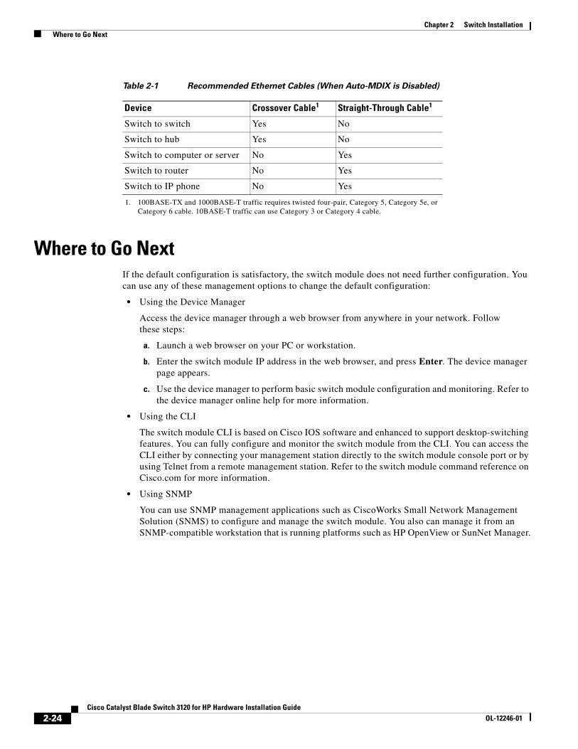
Chapter 2 Switch Installation Where to Go Next
Where to Go NextIf the default configuration is satisfactory, the switch module does not need further configuration. You can use any of these management options to change the default configuration:
• Using the Device Manager
Access the device manager through a web browser from anywhere in your network. Follow these steps:
a. Launch a web browser on your PC or workstation.
b. Enter the switch module IP address in the web browser, and press Enter. The device manager page appears.
c. Use the device manager to perform basic switch module configuration and monitoring. Refer to the device manager online help for more information.
• Using the CLI
The switch module CLI is based on Cisco IOS software and enhanced to support desktop-switching features. You can fully configure and monitor the switch module from the CLI. You can access the CLI either by connecting your management station directly to the switch module console port or by using Telnet from a remote management station. Refer to the switch module command reference on Cisco.com for more information.
• Using SNMP
You can use SNMP management applications such as CiscoWorks Small Network Management Solution (SNMS) to configure and manage the switch module. You also can manage it from an SNMP-compatible workstation that is running platforms such as HP OpenView or SunNet Manager.
Table 2-1 Recommended Ethernet Cables (When Auto-MDIX is Disabled)
Device Crossover Cable1
1. 100BASE-TX and 1000BASE-T traffic requires twisted four-pair, Category 5, Category 5e, or Category 6 cable. 10BASE-T traffic can use Category 3 or Category 4 cable.
Straight-Through Cable1
Switch to switch Yes No
Switch to hub Yes No
Switch to computer or server No Yes
Switch to router No Yes
Switch to IP phone No Yes
2-24Cisco Catalyst Blade Switch 3120 for HP Hardware Installation Guide
OL-12246-01

Chapter 2 Switch Installation Where to Go Next
2-25Cisco Catalyst Blade Switch 3120 for HP Hardware Installation Guide
OL-12246-01
Cisco Catalyst BlaOL-12246-01
C H A P T E R 3
TroubleshootingThis chapter describes these topics for troubleshooting problems:
• Diagnosing Problems, page 3-1
• Clearing the Switch Module IP Address and Configuration, page 3-5
• Replacing a Failed Stack Member, page 3-5
• Locating the Switch Module Serial Number, page 3-6
Diagnosing ProblemsThe LEDs on the switch module front panel provide troubleshooting information. They show power-on self-test (POST) failures, port-connectivity problems, and overall switch module performance. You can also get statistics from the CLI or from an SNMP workstation. See the software configuration guide and the switch command reference on Cisco.com or the documentation that came with your SNMP application for more information.
This section includes these troubleshooting topics:
• Verify the Switch Module POST Results, page 3-1
• Look at the Switch Module LEDs, page 3-2
• Confirm the Switch Module Connections, page 3-2
• Verify the Switch Module Performance, page 3-4
Verify the Switch Module POST ResultsAs the switch module powers on, it begins the POST, a series of tests that runs automatically to ensure that the switch functions properly. It might take several minutes for the switch to complete POST.
When the switch begins POST, the system LED slowly blinks green. When POST completes, the system LED blinks amber. If POST fails, the system LED remains amber. If POST completes successfully, the system LED rapidly blinks green.
Note POST failures are usually fatal. Contact your Cisco technical support representative if your switch does not pass POST.
3-1de Switch 3120 for HP Hardware Installation Guide
Chapter 3 Troubleshooting Diagnosing Problems
Look at the Switch Module LEDsYou must have physical access to the switch module to do this. Look at the port LEDs for troubleshooting information about the switch module. See the “LEDs” section on page 1-5 for a description of the LED colors and their meanings.
Confirm the Switch Module ConnectionsReview this section when troubleshooting switch module connectivity problems.
Bad or Damaged Cable
Always test the cable for marginal damage or failure. A cable might be sufficient to connect at the physical layer but then cause packet corruption because of subtle damage to its wiring or connectors. You can identify this situation because the port will have many packet errors, or the port will constantly lose and regain link. In these situations:
• Exchange the copper or fiber-optic cable with a known, good cable.
• Look for broken or missing pins on cable connectors.
• Rule out any insufficient patch panel connections or media convertors between the source and the destination. If possible, bypass the patch panel or eliminate faulty media convertors, such as fiber-optic-to-copper convertors.
• Try using the cable in another port or interface to see if the problem also exists there.
Ethernet and Fiber Cables
Make sure that you have the correct cable type for the connection:
• For Ethernet, use Category 3 copper cable for 10 Mb/s unshielded twisted pair (UTP) connections. Use either Category 5, Category 5e, or Category 6 UTP for 10/100 or 10/100/1000 Mb/s connections.
• For fiber-optic connectors, verify that you have the correct cable for the distance and port type. Make sure that the ports on the connected device match and that they use the same type of encoding, optical frequency, and fiber type. For more information about cabling, see Appendix B, “Connector and Cable Specifications.”
• For copper connections, determine if a crossover cable was used when a straight-through cable was required, or the reverse. Enable auto-MDIX on the switch module, or replace the cable.
Link Status
Verify that both sides have link. A single broken wire or one shutdown port can cause one side to show link, but the other side does not have link.
A link LED does not guarantee that the cable is fully functional. The cable might have encountered physical stress that causes it to function at a marginal level. If the link light for the port does not come on:
• Connect the cable from the switch module to a known, good device.
• Make sure that both ends of the cable are connected to the correct ports.
• Verify that both devices have power.
3-2Cisco Catalyst Blade Switch 3120 for HP Hardware Installation Guide
OL-12246-01
Chapter 3 Troubleshooting Diagnosing Problems
• Verify that you are using the correct cable type. See Appendix B, “Connector and Cable Specifications,” for more information.
• Test for loose connections. Sometimes a cable appears to be seated, but is not. Disconnect and then reconnect the cable.
SFP Module Port Issues
Use only Cisco small form-factor pluggable (SFP) modules on the switch module. Each Cisco module has an internal serial EEPROM that is encoded with security information. This encoding provides a way for Cisco to identify and validate that the module meets the requirements for the switch module. Test these items:
• Bad or wrong SFP module. Exchange the suspect module with a known, good module. Verify that this module supports this platform. See the “Cisco TwinGig Converter Module” section on page 1-4 for a list of supported SFP modules.
• Use the show interfaces privileged EXEC command to determine the port or module error-disabled, disabled, or shutdown status. Re-enable the port if necessary.
• Make sure that all fiber-optic connections are properly cleaned and securely connected.
Port and Interface Settings
Verify that the port or interface is not disabled or for some reason powered down. If a port or interface is manually shut down on one or the other side of the link, the link does not come up until you re-enable the port. Use the show interfaces privileged EXEC command to determine the port or interface error-disabled, disabled, or shutdown status on both sides of the connection. If necessary, re-enable the port or the interface.
Ping the End Device
Test the end device by pinging it from the directly connected switch module first, and then work your way back port by port, interface by interface, trunk by trunk, until you find the source of the connectivity issue. Make sure that each switch module can identify the end device MAC address in its Content-Addressable Memory (CAM) table.
Spanning Tree Loops
Spanning Tree Protocol (STP) loops can cause serious performance issues that might appear to be port or interface problems. In this situation, the switch module bandwidth is used repeatedly by the same frames, crowding out legitimate traffic.
A unidirectional link can cause loops. This occurs when the traffic that the switch module sends is received by its neighbor, but the switch module does not receive the traffic that is sent from the neighbor. A broken fiber-optic cable, other cabling, or a port issue could cause this one-way communication.
You can enable the UniDirectional Link Detection (UDLD) protocol on the switch module to help identify difficult-to-find unidirectional link problems. UDLD supports a normal mode of operation (the default) and an aggressive mode. In normal mode, UDLD detects unidirectional links because of incorrectly connected interfaces on fiber-optic connections. In aggressive mode, UDLD also detects unidirectional links caused by one-way traffic on fiber-optic and twisted-pair links and by incorrectly connected interfaces on fiber-optic links. For information about enabling UDLD on the switch module, see the “Understanding UDLD” section in the software configuration guide.
3-3Cisco Catalyst Blade Switch 3120 for HP Hardware Installation Guide
OL-12246-01
Chapter 3 Troubleshooting Diagnosing Problems
Verify the Switch Module PerformanceReview this section when you troubleshoot switch module performance problems.
Speed, Duplex, and Autonegotiation
If the port statistics show a large number of alignment errors, frame check sequence (FCS), or late-collisions errors, a speed or duplex mismatch might be the problem.
A common issue with speed and duplex occurs when the duplex settings are mismatched between two switches, between a switch module and a router, or between the switch module and a workstation or server. This can happen when you manually set the speed and duplex or because of autonegotiation issues between the two devices.
These circumstances can result in a mismatch:
• A manually set speed or duplex parameter is different from the manually set speed or duplex parameter on the connected port.
• A port is set to autonegotiate, and the connected port is set to full duplex with no autonegotiation.
To maximize switch module performance and ensure a link, follow one of these guidelines when you set or change the settings for duplex and speed:
• Let both ports autonegotiate both speed and duplex.
• Manually set the speed and duplex parameters for the ports on both ends of the connection.
• If a remote device does not autonegotiate, configure the duplex settings on the two ports to match. The speed parameter can adjust itself even if the connected port does not autonegotiate.
Autonegotiation and Network-Interface Cards
Problems sometimes occur between the switch module and third-party network-interface cards (NICs). By default, the switch module ports and interfaces are set to autonegotiate. It is common for devices such as laptop computers or other devices to also be set to autonegotiate, yet sometimes autonegotiation issues occur.
To troubleshoot autonegotiation problems, try manually setting both sides of the connection. If this does not solve the problem, the firmware or software on your NIC might be causing the problem. Upgrade the NIC driver to the latest version available from the manufacturer.
Cabling Distance
If the port statistics show excessive FCS, late-collision, or alignment errors, verify that the cable distance from the switch module to the connected device meets the recommended guidelines. See the “Cable and Adapter Specifications” section on page B-4 for cabling guidelines.
3-4Cisco Catalyst Blade Switch 3120 for HP Hardware Installation Guide
OL-12246-01
Chapter 3 Troubleshooting Clearing the Switch Module IP Address and Configuration
Clearing the Switch Module IP Address and ConfigurationThis section describes how to reset the switch module by rerunning the initial configuration dialog (system configuration dialog). These are reasons why you might want to reset the switch module:
• You installed the switch module in your network and cannot connect to it because you assigned the wrong IP address.
• You want to clear all the configuration settings from the switch module and assign a new IP address.
Caution This procedure clears the IP address and all configuration information stored on the switch module. Do not follow this procedure unless you want to completely reconfigure the switch module.
To reset the switch module:
1. At the switch module prompt, enter enable, and press Return or Enter.
2. At the Privileged EXEC prompt, switch module#, enter setup and press Return or Enter.
The switch module displays the prompt to run the initial configuration dialog. The switch module now behaves like an unconfigured switch module. You can configure the switch module by using the CLI setup procedure described in Appendix C, “Configuring the Switch with the CLI-Based Setup Program”
Replacing a Failed Stack MemberIf you need to replace a failed stack member, you can hot swap or replace the switch module by following this procedure:
1. Get a replacement switch module that has the same model number as the failed switch module.
2. Power down the failed switch module through the Onboard Administrator.
3. Install the replacement switch module in the server chassis.
If you manually set the member numbers for any members in the stack, you need to manually assign the replacement switch module with the same member number as the failed switch module. To manually assign the member number, install the replacement switch module, and wait for it to boot up. Use the CLI to manually assign the member number (see the software configuration guide for instructions) before you connect the switch module to the stack.
4. Connect the switch to the stack.
5. Make the same Gigabit Ethernet connections on the replacement switch module that were on the failed switch module.
6. Reinstall any transceiver modules and cable connections.
7. Power on the replacement switch through the Onboard Administrator.
The replacement switch module will have the same configuration for all the interfaces as the failed switch module and will function the same as the failed switch module.
3-5Cisco Catalyst Blade Switch 3120 for HP Hardware Installation Guide
OL-12246-01
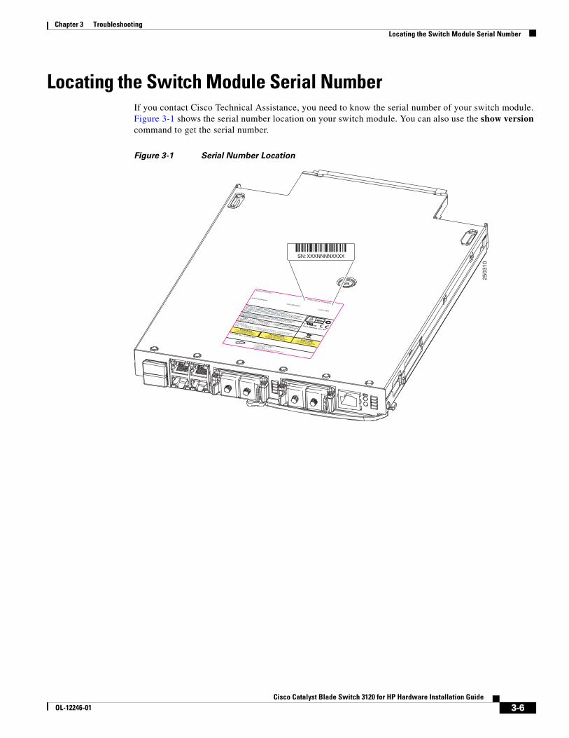
Chapter 3 Troubleshooting Locating the Switch Module Serial Number
Locating the Switch Module Serial NumberIf you contact Cisco Technical Assistance, you need to know the serial number of your switch module. Figure 3-1 shows the serial number location on your switch module. You can also use the show version command to get the serial number.
Figure 3-1 Serial Number Location
2503
10
Cisco Systems, Inc.
IOS VERSION
HP Part No. : 410916-B21
CISCO PID/VID:
CISCO SERIAL NUMBER:
MAC ADDRESS
CLEI CODE
SN: XXXNNNNXXXX
3-6Cisco Catalyst Blade Switch 3120 for HP Hardware Installation Guide
OL-12246-01

Chapter 3 Troubleshooting Locating the Switch Module Serial Number
3-7Cisco Catalyst Blade Switch 3120 for HP Hardware Installation Guide
OL-12246-01
Cisco Catalyst Blade SwOL-12246-01
A
P P E N D I X A Technical SpecificationsThis appendix lists the switch module technical specifications in Table A-1.
See the Regulatory Compliance and Safety Information for the Cisco Catalyst Blade Switch 3000 Series for HP for information about safety compliance and electromagnetic compatibility.
Table A-1 Technical Specifications for the Cisco Catalyst Blade Switch 3120 for HP
Environmental Ranges
Operating temperature 32 to 109°F (0 to 43°C)
Storage temperature –4 to 158°F (–20 to 70°C)
Relative humidity 10 to 85% (noncondensing)
Storage relative humidity 5 to 95% (noncondensing)
Operating altitude Up to 10,000 feet (3048 meters)
Storage altitude Up to 30,000 feet (4572 meters)
Physical Dimensions
Weight 2.8 lbs (1.27 kg)
Dimensions (H x D x W) 1.1 x 7.6 x 10.76 in. (2.8 x 19.3 x 27.3 cm)
A-1itch 3120 for HP Hardware Installation Guide

Appendix A Technical Specifications
A-2Cisco Catalyst Blade Switch 3120 for HP Hardware Installation Guide
OL-12246-01
Cisco Catalyst Blade SwOL-12246-01
A
P P E N D I X B Connector and Cable SpecificationsThis appendix describes the cables and adapters that you use to connect that you use to connect the switch module to other devices. This appendix includes these sections:
• Connector Specifications, page B-1
• Cable and Adapter Specifications, page B-4
Connector SpecificationsThese sections describe the connectors used with the switch:
• 10/100/1000 Ports, page B-1
• 10-Gigabit Ethernet Module Interfaces, page B-3
• Cisco TwinGig Converter Module Ports, page B-3
• Console Port, page B-4
10/100/1000 PortsThe 10/100/1000 Ethernet ports on the switch module use standard RJ-45 connectors. Figure B-1 shows the pinout.
Note You can use the mdix auto interface configuration command in the CLI to enable the automatic medium-dependent interface crossover (auto-MDIX) feature. When the auto-MDIX feature is enabled, the switch module detects the required cable type for copper Ethernet connections and configures the interfaces accordingly. Therefore, you can use either a crossover or a straight-through cable for connections to a copper 10/100/1000 or 1000BASE-T SFP module port on the switch module, regardless of the type of device on the other end of the connection. For configuration information for this feature, refer to the switch module software configuration guide or the switch module command reference.
B-1itch 3120 for HP Hardware Installation Guide
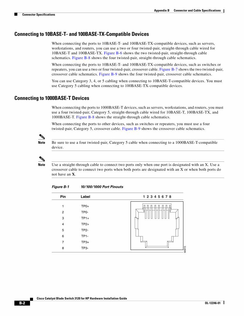
Appendix B Connector and Cable Specifications Connector Specifications
Connecting to 10BASE-T- and 100BASE-TX-Compatible Devices
When connecting the ports to 10BASE-T- and 100BASE-TX-compatible devices, such as servers, workstations, and routers, you can use a two or four twisted-pair, straight-through cable wired for 10BASE-T and 100BASE-TX. Figure B-6 shows the two twisted-pair, straight-through cable schematics. Figure B-8 shows the four twisted-pair, straight-through cable schematics.
When connecting the ports to 10BASE-T- and 100BASE-TX-compatible devices, such as switches or repeaters, you can use a two or four twisted-pair, crossover cable. Figure B-7 shows the two twisted-pair, crossover cable schematics. Figure B-9 shows the four twisted-pair, crossover cable schematics.
You can use Category 3, 4, or 5 cabling when connecting to 10BASE-T-compatible devices. You must use Category 5 cabling when connecting to 100BASE-TX-compatible devices.
Connecting to 1000BASE-T Devices
When connecting the ports to 1000BASE-T devices, such as servers, workstations, and routers, you must use a four twisted-pair, Category 5, straight-through cable wired for 10BASE-T, 100BASE-TX, and 1000BASE-T. Figure B-8 shows the straight-through cable schematics.
When connecting the ports to other devices, such as switches or repeaters, you must use a four twisted-pair, Category 5, crossover cable. Figure B-9 shows the crossover cable schematics.
Note Be sure to use a four twisted-pair, Category 5 cable when connecting to a 1000BASE-T-compatible device.
Note Use a straight-through cable to connect two ports only when one port is designated with an X. Use a crossover cable to connect two ports when both ports are designated with an X or when both ports do not have an X.
Figure B-1 10/100/1000 Port Pinouts60
915
2 31 4 5 6 7 8Pin Label
1
2
3
4
5
6
7
8
TP0+
TP0-
TP1+
TP2+
TP2-
TP1-
TP3+
TP3-
B-2Cisco Catalyst Blade Switch 3120 for HP Hardware Installation Guide
OL-12246-01
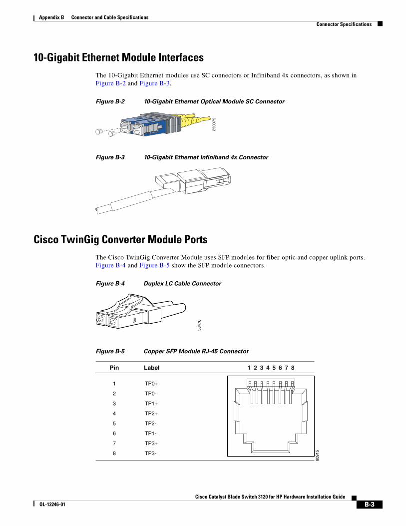
Appendix B Connector and Cable Specifications Connector Specifications
10-Gigabit Ethernet Module InterfacesThe 10-Gigabit Ethernet modules use SC connectors or Infiniband 4x connectors, as shown in Figure B-2 and Figure B-3.
Figure B-2 10-Gigabit Ethernet Optical Module SC Connector
Figure B-3 10-Gigabit Ethernet Infiniband 4x Connector
Cisco TwinGig Converter Module PortsThe Cisco TwinGig Converter Module uses SFP modules for fiber-optic and copper uplink ports. Figure B-4 and Figure B-5 show the SFP module connectors.
Figure B-4 Duplex LC Cable Connector
Figure B-5 Copper SFP Module RJ-45 Connector
2503
75
5847
6
6091
5
2 31 4 5 6 7 8Pin Label
1
2
3
4
5
6
7
8
TP0+
TP0-
TP1+
TP2+
TP2-
TP1-
TP3+
TP3-
B-3Cisco Catalyst Blade Switch 3120 for HP Hardware Installation Guide
OL-12246-01
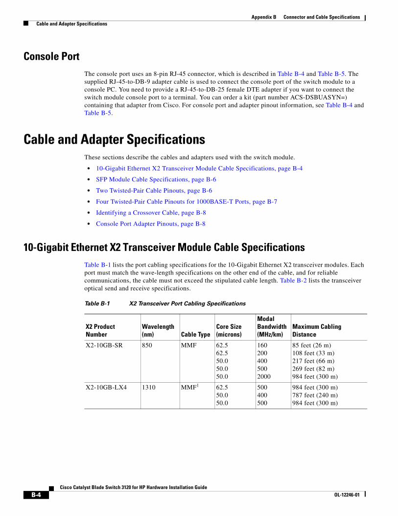
Appendix B Connector and Cable Specifications Cable and Adapter Specifications
Console PortThe console port uses an 8-pin RJ-45 connector, which is described in Table B-4 and Table B-5. The supplied RJ-45-to-DB-9 adapter cable is used to connect the console port of the switch module to a console PC. You need to provide a RJ-45-to-DB-25 female DTE adapter if you want to connect the switch module console port to a terminal. You can order a kit (part number ACS-DSBUASYN=) containing that adapter from Cisco. For console port and adapter pinout information, see Table B-4 and Table B-5.
Cable and Adapter SpecificationsThese sections describe the cables and adapters used with the switch module.
• 10-Gigabit Ethernet X2 Transceiver Module Cable Specifications, page B-4
• SFP Module Cable Specifications, page B-6
• Two Twisted-Pair Cable Pinouts, page B-6
• Four Twisted-Pair Cable Pinouts for 1000BASE-T Ports, page B-7
• Identifying a Crossover Cable, page B-8
• Console Port Adapter Pinouts, page B-8
10-Gigabit Ethernet X2 Transceiver Module Cable Specifications Table B-1 lists the port cabling specifications for the 10-Gigabit Ethernet X2 transceiver modules. Each port must match the wave-length specifications on the other end of the cable, and for reliable communications, the cable must not exceed the stipulated cable length. Table B-2 lists the transceiver optical send and receive specifications.
Table B-1 X2 Transceiver Port Cabling Specifications
X2 Product Number
Wavelength (nm) Cable Type
Core Size (microns)
Modal Bandwidth (MHz/km)
Maximum Cabling Distance
X2-10GB-SR 850 MMF 62.5 62.5 50.0 50.0 50.0
160 200 400 500 2000
85 feet (26 m) 108 feet (33 m) 217 feet (66 m) 269 feet (82 m) 984 feet (300 m)
X2-10GB-LX4 1310 MMF1 62.5 50.0 50.0
500 400 500
984 feet (300 m) 787 feet (240 m) 984 feet (300 m)
B-4Cisco Catalyst Blade Switch 3120 for HP Hardware Installation Guide
OL-12246-01
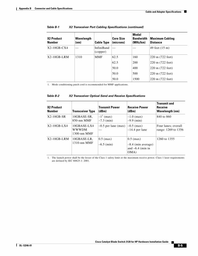
Appendix B Connector and Cable Specifications Cable and Adapter Specifications
X2-10GB-CX4 — InfiniBand (copper)
— — 49 feet (15 m)
X2-10GB-LRM 1310 MMF 62.5
62.5
50.0
50.0
50.0
160
200
400
500
1500
220 m (722 feet)
220 m (722 feet)
220 m (722 feet)
220 m (722 feet)
220 m (722 feet)
1. Mode conditioning patch cord is recommended for MMF applications.
Table B-2 X2 Transceiver Optical Send and Receive Specifications
X2 Product Number Transceiver Type
Transmit Power (dBm)
Receive Power (dBm)
Transmit and Receive Wavelength (nm)
X2-10GB-SR 10GBASE-SR, 850-nm MMF
–11 (max) –7.3 (min)
1. The launch power shall be the lesser of the Class 1 safety limit or the maximum receive power. Class 1 laser requirements are defined by IEC 60825-1: 2001.
–1.0 (max) –9.9 (min)
840 to 860
X2-10GB-LX4 10GBASE-LX4 WWWDM 1300-nm MMF
–0.5 per lane (max) —
–0.5 (max) –14.4 per lane
Four lanes; overall range: 1269 to 1356
X2-10GB-LRM 10GBASE-LR, 1310-nm MMF
0.5 (max)
–6.5 (min)
0.5 (max)
–8.4 (min average) and –6.4 (min in OMA)
1260 to 1355
Table B-1 X2 Transceiver Port Cabling Specifications (continued)
X2 Product Number
Wavelength (nm) Cable Type
Core Size (microns)
Modal Bandwidth (MHz/km)
Maximum Cabling Distance
B-5Cisco Catalyst Blade Switch 3120 for HP Hardware Installation Guide
OL-12246-01
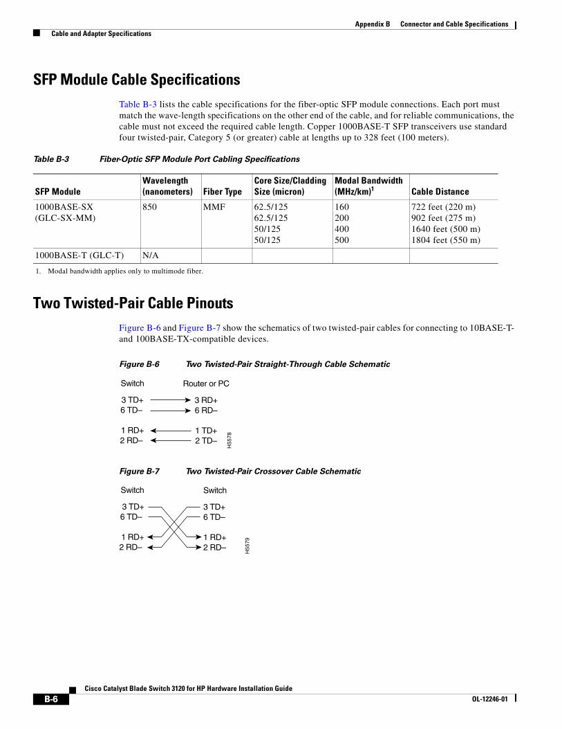
Appendix B Connector and Cable Specifications Cable and Adapter Specifications
SFP Module Cable SpecificationsTable B-3 lists the cable specifications for the fiber-optic SFP module connections. Each port must match the wave-length specifications on the other end of the cable, and for reliable communications, the cable must not exceed the required cable length. Copper 1000BASE-T SFP transceivers use standard four twisted-pair, Category 5 (or greater) cable at lengths up to 328 feet (100 meters).
Two Twisted-Pair Cable PinoutsFigure B-6 and Figure B-7 show the schematics of two twisted-pair cables for connecting to 10BASE-T- and 100BASE-TX-compatible devices.
Figure B-6 Two Twisted-Pair Straight-Through Cable Schematic
Figure B-7 Two Twisted-Pair Crossover Cable Schematic
Table B-3 Fiber-Optic SFP Module Port Cabling Specifications
SFP ModuleWavelength (nanometers) Fiber Type
Core Size/Cladding Size (micron)
Modal Bandwidth (MHz/km)1
1. Modal bandwidth applies only to multimode fiber.
Cable Distance
1000BASE-SX (GLC-SX-MM)
850 MMF 62.5/125 62.5/125 50/125 50/125
160 200 400 500
722 feet (220 m) 902 feet (275 m) 1640 feet (500 m) 1804 feet (550 m)
1000BASE-T (GLC-T) N/A
Switch
3 TD+6 TD–
1 RD+2 RD–
Router or PC
3 RD+6 RD–
1 TD+2 TD–
H55
78
Switch
3 TD+6 TD–
1 RD+2 RD–
Switch
3 TD+6 TD–
1 RD+2 RD–
H55
79
B-6Cisco Catalyst Blade Switch 3120 for HP Hardware Installation Guide
OL-12246-01
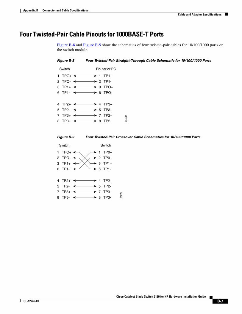
Appendix B Connector and Cable Specifications Cable and Adapter Specifications
Four Twisted-Pair Cable Pinouts for 1000BASE-T PortsFigure B-8 and Figure B-9 show the schematics of four twisted-pair cables for 10/100/1000 ports on the switch module.
Figure B-8 Four Twisted-Pair Straight-Through Cable Schematic for 10/100/1000 Ports
Figure B-9 Four Twisted-Pair Crossover Cable Schematics for 10/100/1000 Ports
1 TPO+
2 TPO-
3 TP1+
6 TP1-
1 TP1+
Switch Router or PC
2 TP1-
3 TPO+
6 TPO-
4 TP2+
5 TP2-
7 TP3+
8 TP3-
4 TP3+
5 TP3-
7 TP2+
8 TP2- 6527
2
1 TPO+
2 TPO-
3 TP1+
6 TP1-
1 TP0+
Switch Switch
2 TP0-
3 TP1+
6 TP1-
4 TP2+
5 TP2-
7 TP3+
8 TP3-
4 TP2+
5 TP2-
7 TP3+
8 TP3- 6527
4
B-7Cisco Catalyst Blade Switch 3120 for HP Hardware Installation Guide
OL-12246-01
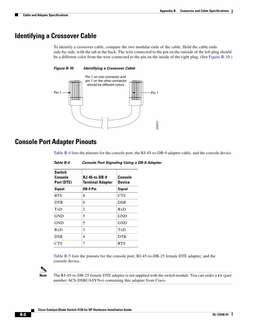
Appendix B Connector and Cable Specifications Cable and Adapter Specifications
Identifying a Crossover CableTo identify a crossover cable, compare the two modular ends of the cable. Hold the cable ends side-by-side, with the tab at the back. The wire connected to the pin on the outside of the left plug should be a different color from the wire connected to the pin on the inside of the right plug. (See Figure B-10.)
Figure B-10 Identifying a Crossover Cable
Console Port Adapter PinoutsTable B-4 lists the pinouts for the console port, the RJ-45-to-DB-9 adapter cable, and the console device.
Table B-5 lists the pinouts for the console port, RJ-45-to-DB-25 female DTE adapter, and the console device.
Note The RJ-45-to-DB-25 female DTE adapter is not supplied with the switch module. You can order a kit (part number ACS-DSBUASYN=) containing this adapter from Cisco.
Pin 1
2009
15
Pin 1
Pin 1 on one connector and pin 1 on the other connectorshould be different colors.
Table B-4 Console Port Signaling Using a DB-9 Adapter
Switch Console Port (DTE)
RJ-45-to-DB-9 Terminal Adapter
Console Device
Signal DB-9 Pin Signal
RTS 8 CTS
DTR 6 DSR
TxD 2 RxD
GND 5 GND
GND 5 GND
RxD 3 TxD
DSR 4 DTR
CTS 7 RTS
B-8Cisco Catalyst Blade Switch 3120 for HP Hardware Installation Guide
OL-12246-01
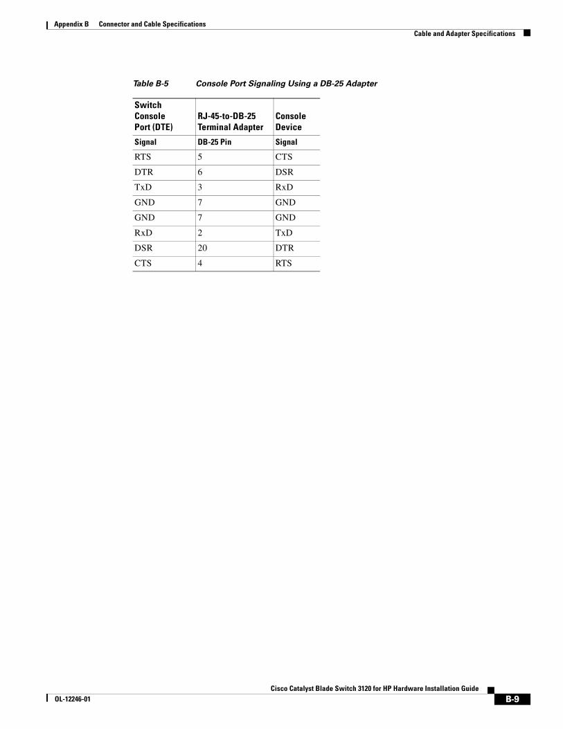
Appendix B Connector and Cable Specifications Cable and Adapter Specifications
Table B-5 Console Port Signaling Using a DB-25 Adapter
Switch Console Port (DTE)
RJ-45-to-DB-25 Terminal Adapter
Console Device
Signal DB-25 Pin Signal
RTS 5 CTS
DTR 6 DSR
TxD 3 RxD
GND 7 GND
GND 7 GND
RxD 2 TxD
DSR 20 DTR
CTS 4 RTS
B-9Cisco Catalyst Blade Switch 3120 for HP Hardware Installation Guide
OL-12246-01

Appendix B Connector and Cable Specifications Cable and Adapter Specifications
B-10Cisco Catalyst Blade Switch 3120 for HP Hardware Installation Guide
OL-12246-01
Cisco Catalyst Blade SwOL-12246-01
A
P P E N D I X C Configuring the Switch with the CLI-Based Setup ProgramThis appendix provides a quick installation and setup procedure for the switch module by using the command-line interface (CLI).
Note For detailed installation procedures, see Chapter 2, “Switch Installation.” For product overview information, see Chapter 1, “Product Overview.”
These are the major steps for a quick installation when using the CLI:
1. Accessing the CLI Through the Console Port, page C-1
2. Connecting to the Console Port, page C-1
3. Completing the Initial Configuration, page C-4
Accessing the CLI Through the Console PortYou can access the CLI on a configured or unconfigured switch module by connecting the console port of the switch module to the serial port on your PC or workstation and accessing the switch module through a Telnet session.
Connecting to the Console PortObtain and make note of this information from your network administrator before you begin the switch module installation:
• Switch IP address
• Subnet mask (IP netmask)
• Default gateway (router)
• Enable secret password (encrypted)
• Enable password (not encrypted)
• Telnet password
• SNMP community strings (optional)
C-1itch 3120 for HP Hardware Installation Guide
Appendix C Configuring the Switch with the CLI-Based Setup Program Accessing the CLI Through the Console Port
Complete these steps:
Step 1 Connect one end of the console cable to the switch module console port. Connect the other end of the cable to the serial port of the computer that is running the terminal emulation application. (See Figure C-1.)
You can use the mdix auto interface configuration command in the CLI to enable the automatic medium-dependent interface crossover (auto-MDIX) feature. When the auto-MDIX feature is enabled, the switch module detects the required cable type for copper Ethernet connections and configures the interfaces accordingly. Therefore, you can use either a crossover or a straight-through cable for connections to a copper 10/100/1000 or 1000BASE-T SFP module port on the switch module, regardless of the type of device on the other end of the connection. For configuration information for this feature, refer to the switch module software configuration guide or the switch module command reference on Cisco.com.
C-2Cisco Catalyst Blade Switch 3120 for HP Hardware Installation Guide
OL-12246-01
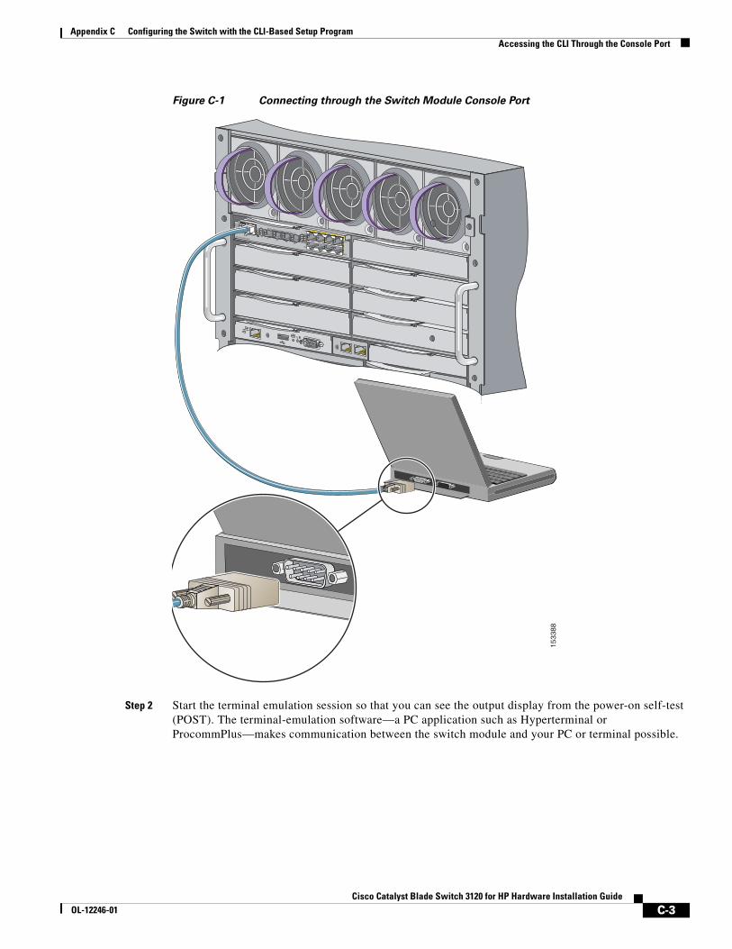
Appendix C Configuring the Switch with the CLI-Based Setup Program Accessing the CLI Through the Console Port
Figure C-1 Connecting through the Switch Module Console Port
Step 2 Start the terminal emulation session so that you can see the output display from the power-on self-test (POST). The terminal-emulation software—a PC application such as Hyperterminal or ProcommPlus—makes communication between the switch module and your PC or terminal possible.
23x
24x
21x
24x
17x
18x
17x
20x
17
20
SYSTSTAT
DLXSPD
CONSOLE
UID
WS-CBS-3020-HPQ
MODE
MEDIA DETECT SFP/R-45 PORTS 17-20
17
20
1819
1533
88
C-3Cisco Catalyst Blade Switch 3120 for HP Hardware Installation Guide
OL-12246-01
Appendix C Configuring the Switch with the CLI-Based Setup Program Accessing the CLI Through the Console Port
Configure the baud rate and character format of the PC or terminal to match these console port default characteristics:
• 9600 baud
• 8 data bits
• 1 stop bit
• No parity
• None (flow control)
Step 3 Wait for the switch module to complete the POST. It might take several minutes for the switch module to complete POST.
Step 4 Verify that POST has completed by confirming that the system and status LEDs remain green.
If the switch module fails POST, the system LED turns amber. POST errors are usually fatal. Call Cisco Systems immediately if your switch module fails POST.
Step 5 Wait for the switch to complete initialization. When you see the prompt, Press Return to Get Started!, press Return or Enter.
Step 6 Make sure that the system and status LEDs are green. This means that the switch module is operating properly.
Step 7 See the “Completing the Initial Configuration” section on page C-4 for instructions on setting up and initially configuring the switch module.
Completing the Initial ConfigurationFollow these steps to complete the setup program and to create an initial configuration for the switch module.
Note For information about automatically configuring the switch module, see the “Assigning the Switch IP Address and Default Gateway” chapter in the switch module configuration guide.
Step 1 After you have pressed Enter or Return after the prompt to start the initial configuration setup program, enter yes at these prompts:
Would you like to terminate autoinstall? [yes]: yes--- System Configuration Dialog ---Continue with configuration dialog? [yes/no]: yes
At any point you may enter a question mark '?' for help.Use ctrl-c to abort configuration dialog at any prompt.Default settings are in square brackets '[]'.
Basic management setup configures only enough connectivityfor management of the system, extended setup will ask youto configure each interface on the system
Would you like to enter basic management setup? [yes/no]: yesConfiguring global parameters:
C-4Cisco Catalyst Blade Switch 3120 for HP Hardware Installation Guide
OL-12246-01
Appendix C Configuring the Switch with the CLI-Based Setup Program Accessing the CLI Through the Console Port
Step 2 Enter a hostname for the switch module after the prompt, and press Return.
The hostname is limited to 20 characters. Do not use -n, where n is a number, as the last character in a hostname for any switch module.
Step 3 Enter an enable secret password, and press Return.
The password can be from 1 to 25 alphanumeric characters, can start with a number, is case sensitive, allows spaces, but ignores leading spaces. The secret password is encrypted, and the enable password is in plain text.
Step 4 Enter an enable password, and press Return.
Step 5 Enter a virtual terminal (Telnet) password, and press Return.
The password can be from 1 to 25 alphanumeric characters, is case sensitive, allows spaces, but ignores leading spaces.
Step 6 (Optional) Configure Simple Network Management Protocol (SNMP) by responding to the prompts.
1. To configure SNMP later, press Return (which applies the default of no). If you accept the default, you can configure SNMP later through the CLI.
Configure SNMP Network Management? [no]:
2. To configure SNMP now, enter yes.
Configure SNMP Network Management? [no]: yesCommunity string [public]: public
Step 7 Enter the interface name (physical interface or VLAN name) of the interface that connects to the management network, and press Return.
Enter vlan1 for the interface name at this prompt.
Step 8 To configure the interface, enter Yes after the prompt, and then enter the switch module IP address and subnet mask. Press Return.
The IP address and subnet mask shown here are examples:
Configuring interface Vlan1:Configure IP on this interface? [yes]:IP address for this interface [10.0.0.1]:Subnet mask for this interface [255.255.255.0] : 255.255.255.0Class A network is 10.0.0.1, 21 subnet bits; mask is /21
Step 9 Enter no when the prompt asks you if you would like to enable the switch module as a cluster command switch. This switch module will be a standalone switch.
Would you like to enable as a cluster command switch? [yes/no]: no
Note The Cisco Catalyst Blade Switch 3020 for HP does not support clustering.
You have now completed the initial configuration of the switch module, and the switch module displays its initial configuration. An example of the output is shown here:
The following configuration command script was created:hostname switch1enable secret 5 $1$cagJ$e4LP91PNazfdADoNAZm6y0enable password enable_passwordline vty 0 15password terminal-passwordsnmp-server community public!
C-5Cisco Catalyst Blade Switch 3120 for HP Hardware Installation Guide
OL-12246-01
Appendix C Configuring the Switch with the CLI-Based Setup Program Accessing the CLI Through the Console Port
!interface Vlan1no shutdownip address 10.0.0.1 255.255.255.0!interface GigabitEthernet0/1!interface GigabitEthernet0/2
. . . (output truncated)
interface GigabitEthernet0/16!end
Step 10 These choices appear:
[0] Go to the IOS command prompt without saving this config.
[1] Return back to the setup without saving this config.
[2] Save this configuration to nvram and exit.
If you want to save the configuration and use it the next time the switch reboots, save it in NVRAM by selecting option 2.
Enter your selection [2]:2
Make your selection, and press Return.
Step 11 Disconnect the blade server serial port or the switch module console port from the PC. See the “Management Options” section on page 1-8 for information about managing the switch module.
C-6Cisco Catalyst Blade Switch 3120 for HP Hardware Installation Guide
OL-12246-01
Cisco Catalyst BlaOL-12246-01
I N D E X
Numerics
10/100/1000 ports
cable lengths 3, 23
connecting to 22, 23
connectors and cables 1 to 2
described 3
description 3
recommended cables 24
10-Gigabit Ethernet module slots described 4
A
accessing the device manager 24
adapter pinouts, terminal
RJ-45-to-DB-25 8
RJ-45-to-DB-9 8
auto-MDIX 23, 1, 2
autonegotiation
default setting 23
troubleshooting 4
B
blade enclosure
architecture 5
description 1
C
cable lengths 3
cables
connecting the stacking cables 16
crossover
connecting to 2
four twisted-pair pinout, 1000BASE-T ports 7
identifying 8
two twisted-pair pinout, 10/100 ports 6
recommended 24
SFP module 6
straight-through
connecting to 2
four twisted-pair pinout, 1000BASE-T ports 7
two twisted-pair pinout 6
X2 transceiver module 4
cabling
10/100/1000 ports 22
auto-MDIX 23, 1, 2
pinouts 6
See also connectors and cables
StackWise cables
cable numbers 8
connecting to 16
cautions 8
Cisco IOS command-line interface 10, 24
Cisco IP Phones, connecting to 22, 24
Cisco TwinGig Converter Module
described 4
installing 18
Class 1 laser warning 2
CLI
accessing through console port 1
using 10, 24
command-line interface
See CLI
configuration examples, network 3
IN-1de Switch 3120 for HP Hardware Installation Guide
Index
connecting
the stacking cables 16
to 10/100/1000 ports 22
to console port 4
connection procedures 22 to 23
connectors and cables
10/100/1000 ports 1 to 2
console port 4 to 9
console port
connecting 3
connectors and cables 4 to 9
conventions, document 8
converter modules
installing and removing 18 to 20
crossover cable
identifying 8
pinout for four twisted-pair, 1000BASE-T ports 7
D
device manager
description 9
how to access 24
diagnosing problems 1
disposal of product warning 2
document conventions 8
duplex
default setting 23
troubleshooting 4
E
electrical codes warning 2
electrical noise, avoiding 3
Ethernet and fiber-optic cable troubleshooting 2
Ethernet cable shielding warning 2
Ethernet port connections warning 2
IN-2Cisco Catalyst Blade Switch 3120 for HP Hardware Installation Gui
examples, network configuration 3
Express Setup 11 to 12
F
features 1 to 8
features overview 1 to 3
front panel
10/100/1000 Ethernet ports 3
10/100 /1000 ports 3
10-Gigabit Ethernet module slots 4
SFP module ports 4
H
health LED 6
I
installation
guidelines 3
prerequisites 5
requirements 3
installation instructions warning 2
installing Cisco TwinGig Converter Modules 18
installing SFP modules 20 to 21
installing the switch module in the blade enclosure 6
installing X2 transceiver modules 18
IP address
assigning through the Onboard Administrator 9
refreshing 13
ways to assign 8
J
jewelry removal warning 2
deOL-12246-01
Index
L
LEDs
Health 6
port 6
POST results 1
stack 5
stack master 6
stack member 6
system 5
troubleshooting with 1 to 2
UID 6
lightning activity warning 2
link status troubleshooting 2
M
managing the switch module
using SNMP 10, 24
using the CLI 10, 24
using the device manager 9, 24
using the Onboard Administrator 10
message URL http
//www.cisco.com/web/learning/index.html 7
N
network configuration examples 3
noise, electrical 3
O
Onboard Administrator
managing the switch module 10
using to assign IP address 9
overheating prevention warning 2
Cisco CaOL-12246-01
P
packing list 4
pinouts
adapters 8
console port 9, 9
crossover cable 8
crossover cables for four twisted-pair, 1000BASE-T ports 7
crossover cables for two twisted-pair 10/100 ports 6
RJ-45-to-DB-25 terminal adapter 9
RJ-45-to-DB-9 terminal adapter 8
SFP module ports 3
straight-through cables
four twisted-pair 1000BASE-T ports 7
two twisted-pair 6
port and interface troubleshooting 3
port LEDs 6
ports
10/100/1000 3
connecting to 23
described 3
recommended cables 24
numbering of 10/100/1000 3
StackWise ports 8
POST
LEDs 1
running at power on 1
procedures
connecting StackWise Plus cables 16
connection 22 to 23
Express Setup 11
installation 6
publications, related 8
IN-3talyst Blade Switch 3120 for HP Hardware Installation Guide
Index
R
recommended configurations for stacking 14
requirements for installing the switch module 3
RJ-45 connector, console port 4
S
safety and handling guidelines 3
safety warnings 2
serial number location 6
SFP modules
bale-clasp latch removal 21
cables 6
connectors 3
description 4
installation 20 to 21
software switch module management 8
specifications 1
speed
default setting 23
troubleshooting 4
stacking caution 13
stack LED 5
stack master
LED 6
setting 12
stack member LED 6
StackWise Plus cables
configuration examples 14
ordering 14
StackWise ports 8
straight-through cable
pinout
four twisted-pair 1000BASE-T ports 7
two twisted-pair 10/100 ports 6
IN-4Cisco Catalyst Blade Switch 3120 for HP Hardware Installation Gui
switch stack
configuration examples 14 to 16
creating 13 to 17
description 13
system LED 5
T
technical specifications 1
Telnet, and accessing the CLI 10, 24
temperature, operating 1
trained and qualified personnel warning 2
troubleshooting
bad or damaged cable 2
connection problems 2
diagnosing problems 1
Ethernet and fiber-optic cables 2
link status 2
ping end device 3
port and interface settings 3
POST 1
spanning-tree loops 3
speed, duplex, and autonegotiation 4
switch performance 4
with LEDs 1 to 2
TwinGig Converter Module
See Cisco TwinGig Converter Module
U
UID LED 6
unit identifier
See UID
deOL-12246-01
Index
W
warnings
Class 1 laser 2
defined 8
disposal of product 2
electrical codes 2
Ethernet cable shielding 2
Ethernet port connections 2
installation 2
installation instructions 2
jewelry removal 2
lightning activity 2
overheating prevention 2
trained and qualified personnel 2
X
X2 transceiver modules
described 4
installing 18
installing and removing 18 to 20
removing 19
See also 10-Gigabit Ethernet module slot
Cisco CaOL-12246-01
IN-5talyst Blade Switch 3120 for HP Hardware Installation Guide

Index
IN-6Cisco Catalyst Blade Switch 3120 for HP Hardware Installation Gui
deOL-12246-01