Embed Size (px)
Citation preview
Cisco Application Networking for IBM Lotus Domino Web Access Deployment Guide
Cisco Validated Design
December 28, 2007
Preface
Document PurposeThis document provides implementation and configuration information for the Cisco Application Control Engine (Cisco ACE) and the Cisco Wide Area Application Services (Cisco WAAS) to provide performance and load balancing to the Lotus Domino Web Access ((also known as Lotus iNotes) application.
PrerequisitesThe following prerequisites are required to understand, configure and deploy the Lotus Domino Web Access solution:
• Working knowledge of Lotus Domino Web Access.
• Experience with basic networking and troubleshooting.
• Experience with installation and acceptance of the products covered by this network design.
• Working knowledge of the Cisco Internetworking Operating System (IOS) .
Document OrganizationThe following table provides a brief description of each section.
Americas Headquarters:
© 2007 Cisco Systems, Inc. All rights reserved.
Cisco Systems, Inc., 170 West Tasman Drive, San Jose, CA 95134-1706 USA
Solution Overview
Solution Overview
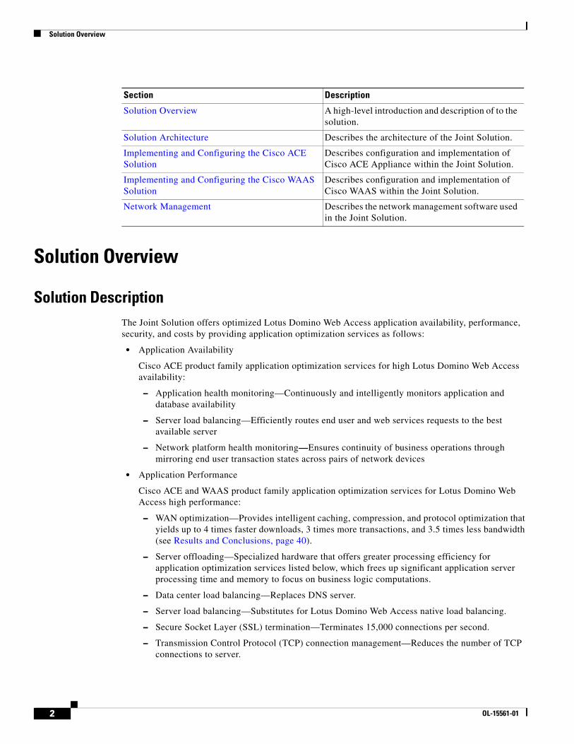
Solution DescriptionThe Joint Solution offers optimized Lotus Domino Web Access application availability, performance, security, and costs by providing application optimization services as follows:
• Application Availability
Cisco ACE product family application optimization services for high Lotus Domino Web Access availability:
– Application health monitoring—Continuously and intelligently monitors application and database availability
– Server load balancing—Efficiently routes end user and web services requests to the best available server
– Network platform health monitoring—Ensures continuity of business operations through mirroring end user transaction states across pairs of network devices
• Application Performance
Cisco ACE and WAAS product family application optimization services for Lotus Domino Web Access high performance:
– WAN optimization—Provides intelligent caching, compression, and protocol optimization that yields up to 4 times faster downloads, 3 times more transactions, and 3.5 times less bandwidth (see Results and Conclusions, page 40).
– Server offloading—Specialized hardware that offers greater processing efficiency for application optimization services listed below, which frees up significant application server processing time and memory to focus on business logic computations.
– Data center load balancing—Replaces DNS server.
– Server load balancing—Substitutes for Lotus Domino Web Access native load balancing.
– Secure Socket Layer (SSL) termination—Terminates 15,000 connections per second.
– Transmission Control Protocol (TCP) connection management—Reduces the number of TCP connections to server.
Section Description
Solution Overview A high-level introduction and description of to the solution.
Solution Architecture Describes the architecture of the Joint Solution.
Implementing and Configuring the Cisco ACE Solution
Describes configuration and implementation of Cisco ACE Appliance within the Joint Solution.
Implementing and Configuring the Cisco WAAS Solution
Describes configuration and implementation of Cisco WAAS within the Joint Solution.
Network Management Describes the network management software used in the Joint Solution.
2 OL-15561-01
Solution Overview
– Server health monitoring—Substitutes for Lotus Domino Web Access native server health monitoring.
– Traffic compression—Scalable gzip functionality.
– Object caching—Reduce requests to server.
• Application Security
Cisco ACE product family application optimization services for optimized Lotus Domino Web Access data security:
– SSL termination—Efficiently encrypts and decrypts SSL-enabled traffic which facilitates the use of intrusion detection and prevention solutions before traffic reaches the servers
– End user access control—Provides access control lists (ACLs) to protect client-to-server traffic from worms and intruders that attack vulnerable open server ports not used by the application
• Virtualization of Application Optimization Services
Virtualization of application optimization services herein supplies such services for multiple Lotus Domino Web Access solutions as well as other enterprise applications (see Figure 1).
3OL-15561-01
Solution Overview
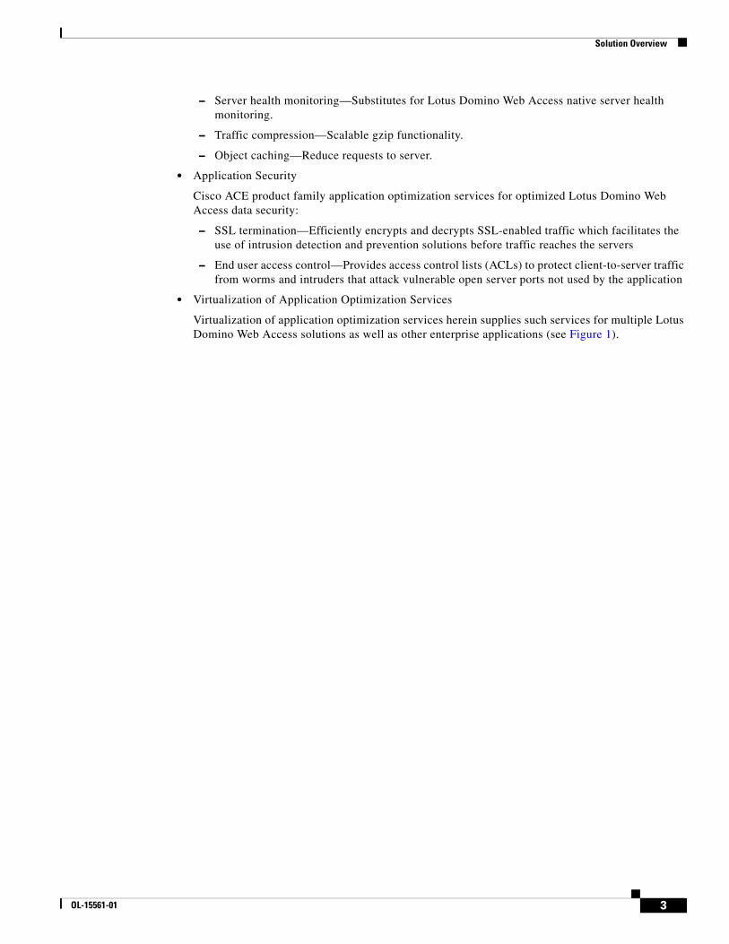
Figure 1 Virtualization of Application Optimization Services
The application optimization services of the Joint Solution reside both in the data center and the branch to offer end-to-end value, from branch and remote users, all the way through to the database and information storage.
• Data Center Application Optimization Services
Cisco ACE and Cisco WAAS reside in the data center and are arranged to provide virtualized application optimization services for multiple Lotus Domino Web Access deployments as well as other enterprise applications.
Because of their unique location, these solutions can take intelligent action on the end user traffic before it is routed to the Lotus Domino Web Access servers, including load balancing, server health monitoring, SSL decryption, TCP connection consolidation, and security access control.
While some of these functions could be provided natively by the Lotus Domino Web Access application or third-party server based solutions, Cisco networking provides these services cost-effectively, freeing up server processing and memory needs to focus on business logic computation.
• Wide Area Application Optimization Services
Branch Users
MicrosoftSharePoint
Cisco WAAS
Cisco WAAS Cisco ACE Cisco AXG
WAN
Cisco ApplicationNetworking Solutions
Databaseand
Storage
OtherBEAWebLogic
IBMWebSphere
OracleSiebel
Remote Users
Data Center
Web Services
2229
17
4 OL-15561-01
Solution Overview
Cisco WAAS also resides in the branch office and is arranged to provide virtualized application optimization services for all application users in that location. Together with the data center, Cisco WAAS deployment, the two offer a WAN optimization service through the use of intelligent caching, compression, and protocol optimization.
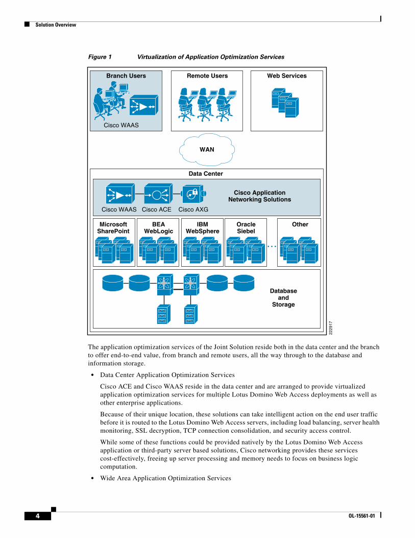
When the Lotus Domino Web Access servers respond to end user requests, the response is compressed and then most efficiently passed across the WAN, with minimal bandwidth usage and maximum speed. Commonly used information is cached both at the Cisco WAAS solution in the branch as well as in the Cisco ACE solution in the data center, which significantly reduces the burden on the servers and the WAN (see Figure 2.)
Process Flow
Figure 2 Process Flow
Client isperforming sitenavigation and
downloads
Does any of the content reside on the local WAE – If yes, provide it to theclient, otherwise obtain from the server.
Has the file to be downloaded been downloaded before and is now storedin the local WAE cache – If yes, forward the file to the client via the
local WAE, otherwise obtain the file from the server.
Note that if data must be retrieved from the server the Local WAEwill apply compression algorithms to data.
This is the network with a set bandwidth value with some notable delay.
Traffic/Data from the Client WAE is uncompressed and forwarded to the Data Center Network.
Traffic/Data from the Data Center will have a compression algorithmapplied to it by the Data Center WAE and forwarded to the Client Network.
Note that Data Center WAE will cache data andprovide to the local servers.
The ACE will verify the servers are active usinghealth checks and remove any that are non-operational.
Traffic/Data from the Data Center WAE is now load balanced to theservers according to the parameter set the ACE.
The ACE will perform Layer 4 thru Layer 7 rules (dependant on theapplication) to the traffic/data, this includes SSL offload and TCP reuse.
Data Center Containing:Core, Aggregation,Access and Servers
WAN Network
Client Side/Branch
WAE
WAE
ACE
2227
92
5OL-15561-01
Solution Architecture
Solution Architecture
Lotus Domino Web Access Application OverviewThe scope of the solution was to provide performance benefits and reduce resource loading on the server farms for the Lotus Domino Web Access application. The IBM Lotus Domino Web Access is the flexible, high-function web browser-based client option to use the reliable, security-rich messaging and collaboration capabilities of IBM Lotus Domino software, online and offline. With the IBM Lotus Domino Web Access software, users have capabilities similar to those included in the IBM Lotus Notes thick-client software, delivered through a web browser.
The Cisco WAAS provided performance benefits to the Lotus Domino Web Access by providing optimization to the traffic/data flowing across the WAN and caching data at the local WAASs. The cached data reduces the amount of traffic flowing across the WAN, allowing for more transactions/observations to take place. The Cisco ACE reduces resource loading on the server farm by providing load-balancing on the data that was bound for the server farm.
6 OL-15561-01
Solution Architecture
Application and Application Networking Architecture
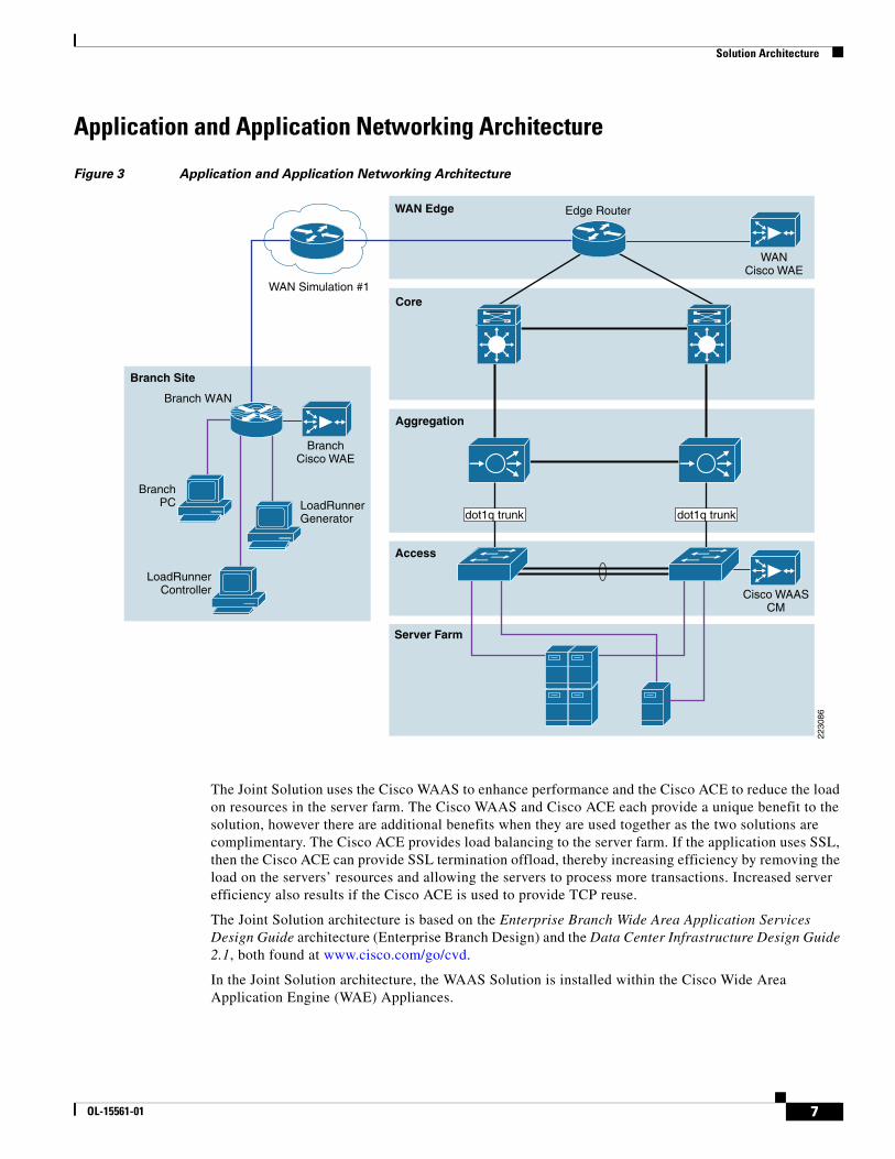
Figure 3 Application and Application Networking Architecture
The Joint Solution uses the Cisco WAAS to enhance performance and the Cisco ACE to reduce the load on resources in the server farm. The Cisco WAAS and Cisco ACE each provide a unique benefit to the solution, however there are additional benefits when they are used together as the two solutions are complimentary. The Cisco ACE provides load balancing to the server farm. If the application uses SSL, then the Cisco ACE can provide SSL termination offload, thereby increasing efficiency by removing the load on the servers’ resources and allowing the servers to process more transactions. Increased server efficiency also results if the Cisco ACE is used to provide TCP reuse.
The Joint Solution architecture is based on the Enterprise Branch Wide Area Application Services Design Guide architecture (Enterprise Branch Design) and the Data Center Infrastructure Design Guide 2.1, both found at www.cisco.com/go/cvd.
In the Joint Solution architecture, the WAAS Solution is installed within the Cisco Wide Area Application Engine (WAE) Appliances.
Server Farm
WAN Simulation #1
BranchPC
Access
Aggregation
WAN Edge
Core
Branch Site
2230
86
Edge Router
Branch WAN
WANCisco WAE
LoadRunnerGenerator
LoadRunnerController
BranchCisco WAE
Cisco WAASCM
dot1q trunk dot1q trunk
7OL-15561-01
Solution Architecture
Enterprise Branch
The enterprise branch design shows the Cisco WAE appliance connected to the local branch router, typically a Cisco Integrated Services Router (ISR). The design provides scalability and availability as compared to installing a Cisco WAAS Network Module within a Cisco ISR as the Cisco ISR must share its resources.
HP Mercury LoadRunner, running on a personal computer in the branch, simulates users that would perform certain tasks in the application.
The traffic is redirected to the Cisco WAE through the Web Cache Communications Protocol (WCCP) from the branch router. The Cisco WAE performs the following functions:
• Locally cached—If the data that is being requested is locally cached, the Cisco WAE responds to the requestor with the cached data and requests only required data from the server farm. This allows the WAN to become more efficient as only “needed data” requested.
• New data—If the data that is being forwarded to the server farm or coming from the server farm, the Cisco WAE performs compression algorithms on the data, allowing for the WAN to become more efficient.
WAN Simulation
The WAN simulator provide simulations of standard T1. The following simulations was used:
• WAN Type 1 (Intracontinental)
– Bandwidth: 1.544 Mbps, ESF, B8ZS
– Delay: 100 mS
– Loss: Drop one packet in every 1000 packets
• WAN Type 2 (Intercontinental)
– Bandwidth: 512 Kbps, ESF, B8ZS
– Delay: 200 mS
– Loss: Drop one packet in every 500 packets
Data Center
For this design, the ACE Appliance is targeted for a small-to-medium data center (DC). The DC follows the design guidelines found in the Data Center Infrastructure Design Guide found at the following URL: http://www.cisco.com/go/srnd
The design consists of a DC WAN router, a collapsed core/aggregation, access, and the server farm (where the application resides). In this document, the focus will be on the DC WAN router, aggregation, and the server farm. The core provides routing to and from the DC WAN router and the aggregation. The access provide Layer 2 connectivity for the server farms to the aggregation. For larger deployments, one should consider a separate core and aggregation layers, or a one-arm deployment where the ACE Appliance connects to a Cisco 6500. For more information, refer to the following URL:
http://www.cisco.com/en/US/partner/products/ps7027/tsd_products_support_series_home.html
8 OL-15561-01
Solution Architecture
The DC WAN router performs the same function as the branch WAN router by redirecting traffic to the DC WAE. The DC WAE performs the following:
• Locally cached—If the data that is being requested is locally cache, the WAE responds to the requestor with the cached data and requests only required data from the branch. This allows the WAN to become more efficient as only “needed data” is requested.
• New data—If the data is being forwarded to the branch or coming from the branch, the WAE performs compression algorithms on the data, allowing for the WAN to become more efficient.
Within a Cisco WAAS topology, each Cisco WAE runs a process called central management system (CMS). The CMS process provides SSL-encrypted bidirectional configuration synchronization of the Cisco WAAS Central Manager and the Cisco WAE devices. The CMS process is also used to exchange reporting information and statistics at a configurable interval. When the administrator applies configuration or policy changes to a Cisco WAE device or a group of Cisco WAE devices (a device group), the Cisco WAAS Central Manager automatically propagates the changes to each of the managed Cisco WAE devices. Cisco WAE devices that are not available to receive the update will receive the update the next time they become available.
The aggregation segment contains the ACE Appliance. The ACE Appliance provides the following:
• Virtualization—Device partitioning, where the Cisco ACE has multiple contexts. Each context can be configured for different applications and each context is independent of the other. The Cisco ACE is configured with Admin context and the Lotus Domino Web Access context. Note that the Cisco ACE can support up to 20 contexts (dependant on the license)
• Session Persistence—The ability to forward client requests to the same server for the duration of the session. The Lotus Domino Web Access application requires cookie sticky session persistence. The configuration of the cookie session persistence was Cisco ACE inserted cookie, which allows the Cisco ACE to insert its own cookie. This allows the Cisco ACE to control the session and perform load balancing using cookie session persistence.
• Transparent Interception—Performs a NAT function to conceal the real server IP address that is residing in the server farm. The Lotus iNotes context is configured with a Virtual IP (VIP) that provides a single address for the users to use connect to the server farm with. This allows the users to access the Lotus Domino Web Access application by placing a single IP in the web browser.
• Allowed Server Connections—The maximum number of active connections value on a per-server basis and/or globally to the server farm. In the Lotus Domino Web Access application, the maximum number of connections were allowed. Note that this should be re-adjusted depending on the number of applications that will utilize the Cisco ACE.
• Health Monitoring—Used to track the state of the server and determining its ability processing connections in the server farm. The Lotus iNotes context used TCP probes to verify if the Lotus Domino Web Access servers were available to process application connections.
The ACE Appliance provides load balancing of the traffic bound to the server farm using one of the following methods:
• Round Robin
• Weighted Round Robin
• Least Connections
• Hash address
• Hash cookie
• Hash Header
• Hash URL
9OL-15561-01
Server Farm
The ANS solution for Lotus Domino Web Access, least connections was used to provide load balancing. Least connections selects the server with the fewest number of connections based on server weight. The Cisco ACE Appliance is also used to provide SSL offload and TCP reuse.
The Cisco ACE redundancy used was Inter-chassis. Inter-chassis is a Cisco ACE in one chassis is protected by a Cisco ACE in a peer-chassis connected by a fault tolerant (FT) VLAN. The FT is used to transmit flow-state information, configuration synchronization information, and the redundancy heartbeat.
Server FarmThe server farm consisted of two Lotus Domino Web Access Web Access Servers (called Lotus Domino 8.0 Servers). Each server is configured using Lotus Domino Web Access Admin 7.0.2. The servers reside on the Windows 2003 Enterprise Server operating system. Quad Xeon processors is the hardware used to run the application and server, running at 1.60Ghz with 4G of RAM and one 140 G-serial attached SCSI hard drive.
The GigabitEthernet network interface cards are "nic-teamed" for redundancy.
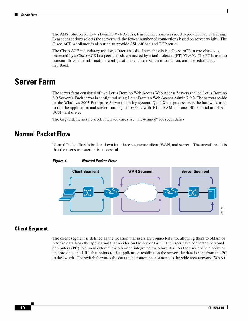
Normal Packet FlowNormal Packet flow is broken down into three segments: client, WAN, and server. The overall result is that the user's transaction is successful.
Figure 4 Normal Packet Flow
Client Segment
The client segment is defined as the location that users are connected into, allowing them to obtain or retrieve data from the application that resides on the server farm. The users have connected personal computers (PC) to a local external switch or an integrated switch/router. As the user opens a browser and provides the URL that points to the application residing on the server, the data is sent from the PC to the switch. The switch forwards the data to the router that connects to the wide area network (WAN).
WAN Segment Server SegmentClient Segment
2227
95
10 OL-15561-01
Server Farm
WAN Segment
The WAN provides the connectivity from the client location to the data center where the server farm is located. The WAN is provided by a service provider (SP) with a given SLA. The WAN inherently introduces delay and packet-loss to the data traffic (packets).
Server Segment
The server segment is the actual data center that consists of a highly available and resilient core, aggregation, and access. The core routes the data traffic to and from the WAN and the aggregation layer. The aggregation layer provides consolidation of multiple access layers and routes the access layer traffic into the core. The aggregation layer also takes the data traffic from the core layer and sends it to the appropriate access layer. The access layer provides connectivity to the server farm where the applications reside. The data traffic (URL, per the example) from the client segment transverses the data center until the data traffic is received by the appropriate server. The server’s application responds to the request and responds back to the user by forwarding the appropriate data back the client segment.
Response Times
Transaction response times consists of server response time and WAN round trip time. Overall transaction time is directly affected by the WAN round trip time and the server response time. The transaction time correlates to the end-user experience. Delays in the WAN or the time to process a request on a server lead to a longer wait times for data to be viewed by the end-user.
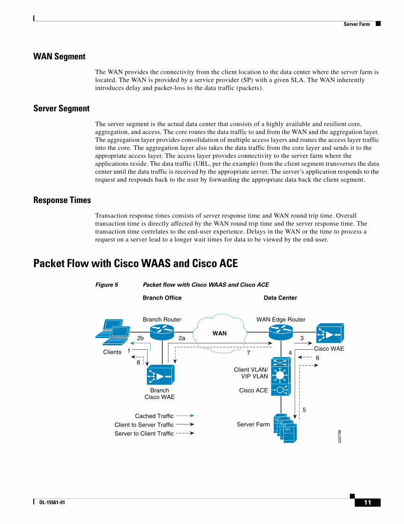
Packet Flow with Cisco WAAS and Cisco ACE
Figure 5 Packet flow with Cisco WAAS and Cisco ACE
Data CenterBranch Office
2b
1
8
2a
7 4
3
Cisco WAE
Branch Router
Server Farm
Client VLAN/VIP VLAN
Cisco ACE
Cached Traffic
WAN Edge Router
2227
96
WAN
BranchCisco WAE
Client to Server Traffic
Server to Client Traffic
6
5
Clients
11OL-15561-01

Server Farm
The following sequence describes the handshake between a client and the server farm and the data transfer phase:
Step 1 The client sends a SYN packet to the server farm VIP address. The packet is forwarded to the branch router. The branch router intercepts the packet with WCCP and forwards it to the branch Cisco WAE appliance.
Step 2 2.a.) The branch Cisco WAE applies a new TCP option (0x21) to the packet if the application is identified for optimization by an application classifier. The branch Cisco WAE adds its device ID and application policy support to the new TCP option field. This option is examined and understood by other Cisco WAEs in the path as the ID and policy fields of the initial Cisco WAE device. The initial ID and policy fields are not altered by another Cisco WAE. The packet is forwarded to the branch router and then to the WAN. b.) During the data transfer phase, if the requested data are in its cache, the branch Cisco WAE returns its cached data to the client. Traffic does not travel through the WAN to the server farm. Hence both response time and WAN link utilization are improved.
Step 3 The packet arrives on the WAN edge router. The WAN edge router intercepts the packet with WCCP and forwards the packet to the data center Cisco WAE.
Step 4 The data center Cisco WAE inspects the packet. Finding that the first device ID and policy is populated, it updates the last device ID field (first device ID and policy parameters are unchanged). The data center Cisco WAE forwards the packet to the WAN edge router. The edge router forwards it to the Cisco ACE. The Cisco ACE forwards the packet to the server farm VLAN with TCP option 21 removed. TCP options are usually ignored by the server, even if it is still in place. The Cisco ACE performs load balancing to the data traffic. Other functions the Cisco ACE performs include SSL offload, TCP reuse, cookie and IP sticky pertinence.
Step 5 The following steps are for reverse traffic flow. The server farm sends the SYN/ACK packet back to the client with no TCP option. The packet from the server farm VLAN is matched and forwarded to the Cisco ACE and then to the WAN edge router. The WAN edge router forwards the packet to the data center Cisco WAE. The data center Cisco WAE marks the packet with TCP option 0x21. During the data transfer phase, the data center Cisco WAE caches the data if the data are not in its cache.
Step 6 The data center Cisco WAE sends the packet to the WAN edge router.
Step 7 The packet travels through the WAN and arrives at the branch router. The branch router intercepts the packet and forwards it to the branch Cisco WAE. The branch Cisco WAE is aware of the Cisco WAE in the data center because the SYN/ACK TCP option 0x21 contains an ID and application policy. The auto-negotiation of the policy occurs as the branch Cisco WAE compares its application-specific policy to that of its remote peer defined in the TCP option. At this point, the data center Cisco WAE and branch Cisco WAE have determined the application optimizations to apply on this specific TCP flow. During the data transfer phase, the branch Cisco WAE caches the data if the data are not in its cache.
Step 8 The packet is forwarded to the branch router and then to the client.
12 OL-15561-01
Implementing and Configuring the Cisco ACE Solution
Implementing and Configuring the Cisco ACE Solution
Implementation
Implementation Overview
The ACE Appliance used in this solution is deployed at data center aggregation layer. The ACE Appliance is deployed in routed mode, where the client and server side VLANs each support unique IP subnet. In this deployment mode, the ACE Appliance acts as the default gateway for the application servers.
Implemented Features
Key features implemented on the ACE Appliance to support this application are as follows.
• Layer 4/Layer 7 load balancing
• Persistence based on the ACE inserted cookie
• SSL termination
• Server health monitoring
• Connection replication for stateful failover
• Least connections predictor used for load balancing
What Was Not Implemented/Tested
TCP reuse was not implemented in this solution.
13OL-15561-01
Implementing and Configuring the Cisco ACE Solution
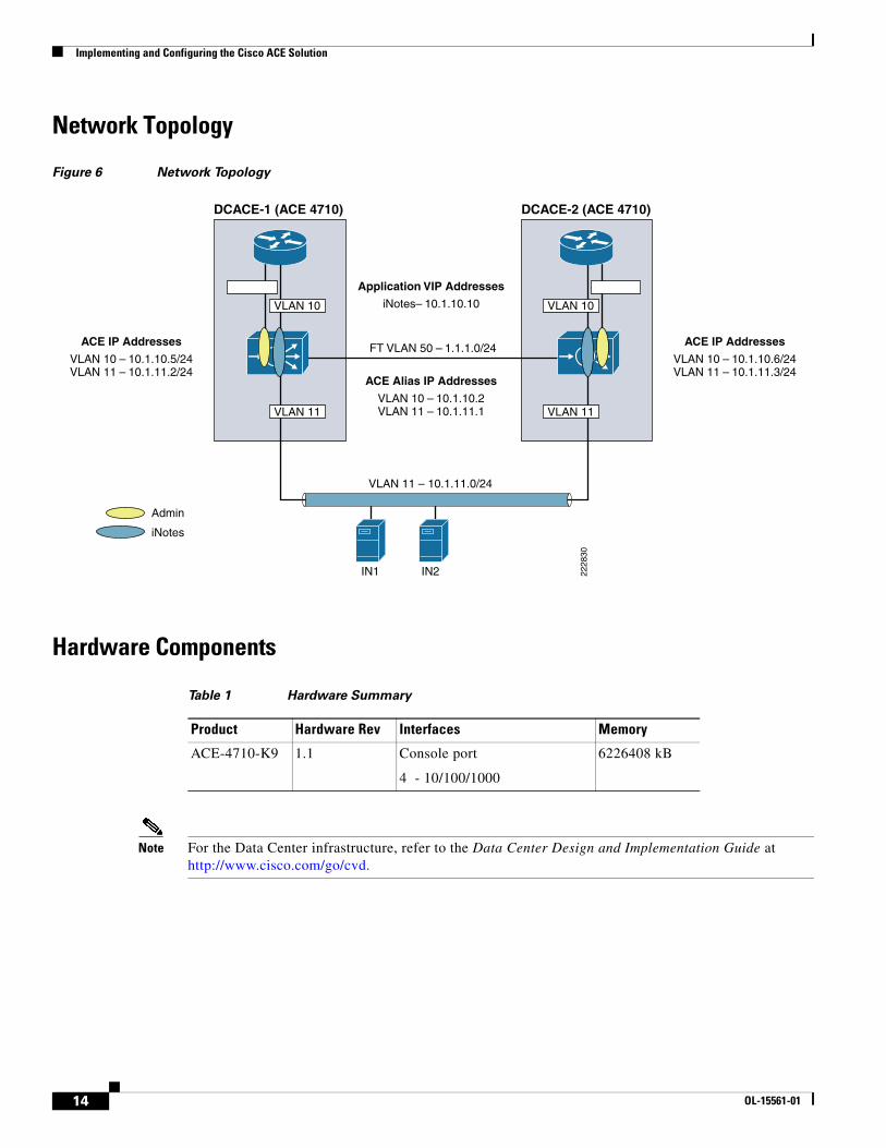
Network Topology
Figure 6 Network Topology
Hardware Components
Note For the Data Center infrastructure, refer to the Data Center Design and Implementation Guide at http://www.cisco.com/go/cvd.
ACE Alias IP Addresses
VLAN 10 – 10.1.10.2VLAN 11 – 10.1.11.1
ACE IP Addresses
VLAN 10 – 10.1.10.5/24VLAN 11 – 10.1.11.2/24
ACE IP Addresses
VLAN 10 – 10.1.10.6/24VLAN 11 – 10.1.11.3/24
Application VIP Addresses
iNotes– 10.1.10.10
FT VLAN 50 – 1.1.1.0/24
Admin
iNotes
2228
30
DCACE-1 (ACE 4710) DCACE-2 (ACE 4710)
IN1 IN2
VLAN 11 – 10.1.11.0/24
VLAN 11
VLAN 10
VLAN 11
VLAN 10
Table 1 Hardware Summary
Product Hardware Rev Interfaces Memory
ACE-4710-K9 1.1 Console port
4 - 10/100/1000
6226408 kB
14 OL-15561-01
Implementing and Configuring the Cisco ACE Solution
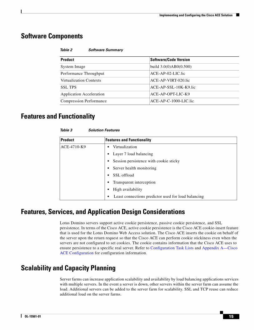
Software Components
Features and Functionality
Features, Services, and Application Design ConsiderationsLotus Domino servers support active cookie persistence, passive cookie persistence, and SSL persistence. In terms of the Cisco ACE, active cookie persistence is the Cisco ACE cookie-insert feature that is used for the Lotus Domino Web Access solution. The Cisco ACE inserts the cookie on behalf of the server upon the return request so that the Cisco ACE can perform cookie stickiness even when the servers are not configured to set cookies. The cookie contains information that the Cisco ACE uses to ensure persistence to a specific real server. Refer to Configuration Task Lists and Appendix A—Cisco ACE Configuration for configuration information.
Scalability and Capacity Planning Server farms can increase application scalability and availability by load balancing applications services with multiple servers. In the event a server is down, other servers within the server farm can assume the load. Additional servers can be added to the server farm for scalability. SSL and TCP reuse can reduce additional load on the server farms.
Table 2 Software Summary
Product Software/Code Version
System Image build 3.0(0)AB0(0.500)
Performance Throughput ACE-AP-02-LIC.lic
Virtualization Contexts ACE-AP-VIRT-020.lic
SSL TPS ACE-AP-SSL-10K-K9.lic
Application Acceleration ACE-AP-OPT-LIC-K9
Compression Performance ACE-AP-C-1000-LIC.lic
Table 3 Solution Features
Product Features and Functionality
ACE-4710-K9 • Virtualization
• Layer 7 load balancing
• Session persistence with cookie sticky
• Server health monitoring
• SSL offload
• Transparent interception
• High availability
• Least connections predictor used for load balancing
15OL-15561-01
Implementing and Configuring the Cisco ACE Solution
High AvailabilityRedundancy (or fault tolerance) uses a maximum of two Cisco ACE appliances to ensure that the network remains operational even if one of the appliances becomes unresponsive. Redundancy ensures that your network services and applications are always available. Redundancy provides seamless switchover of flows in case an Cisco ACE becomes unresponsive or a critical host or interface fails. Redundancy supports the following network applications that require fault tolerance:
• Mission-critical enterprise applications
• Banking and financial services
• E-commerce
• Long-lived flows such as FTP and HTTP file transfers
For more information on configuring high availability (HA) on the Cisco ACE Appliance, refer to the following URL:
http://cisco.com/en/US/products/ps7027/products_configuration_guide_chapter09186a00807c64d3.html
For the specific HA setup for this design, view the complete Admin context configuration in Appendix A—Cisco ACE Configuration.
Configuration Task ListsThis section describes the steps necessary to configure the equipment.
Installing and Configuring Cisco ACE Appliance
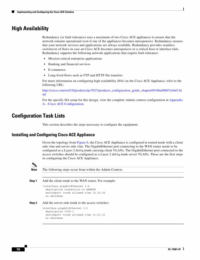
Given the topology from Figure 6, the Cisco ACE Appliance is configured in routed mode with a client side vlan and server side vlan. The GigabitEthernet port connecting to the WAN router needs to be configured as a Layer-2 dot1q trunk carrying client VLANs. The GigabitEthernet port connected to the access switches should be configured as a Layer 2 dot1q trunk server VLANs. These are the first steps in configuring the Cisco ACE Appliance.
Note The following steps occur from within the Admin Context.
Step 1 Add the client trunk to the WAN router. For example:
!interface gigabitEthernet 1/4 description connection to WANRTR switchport trunk allowed vlan 10,20,30 no shutdown
Step 2 Add the server-side trunk to the access switches:
interface gigabitEthernet 1/1 description 3750-1 switchport trunk allowed vlan 11,21,31 no shutdown
16 OL-15561-01
Implementing and Configuring the Cisco ACE Solution
Virtualization
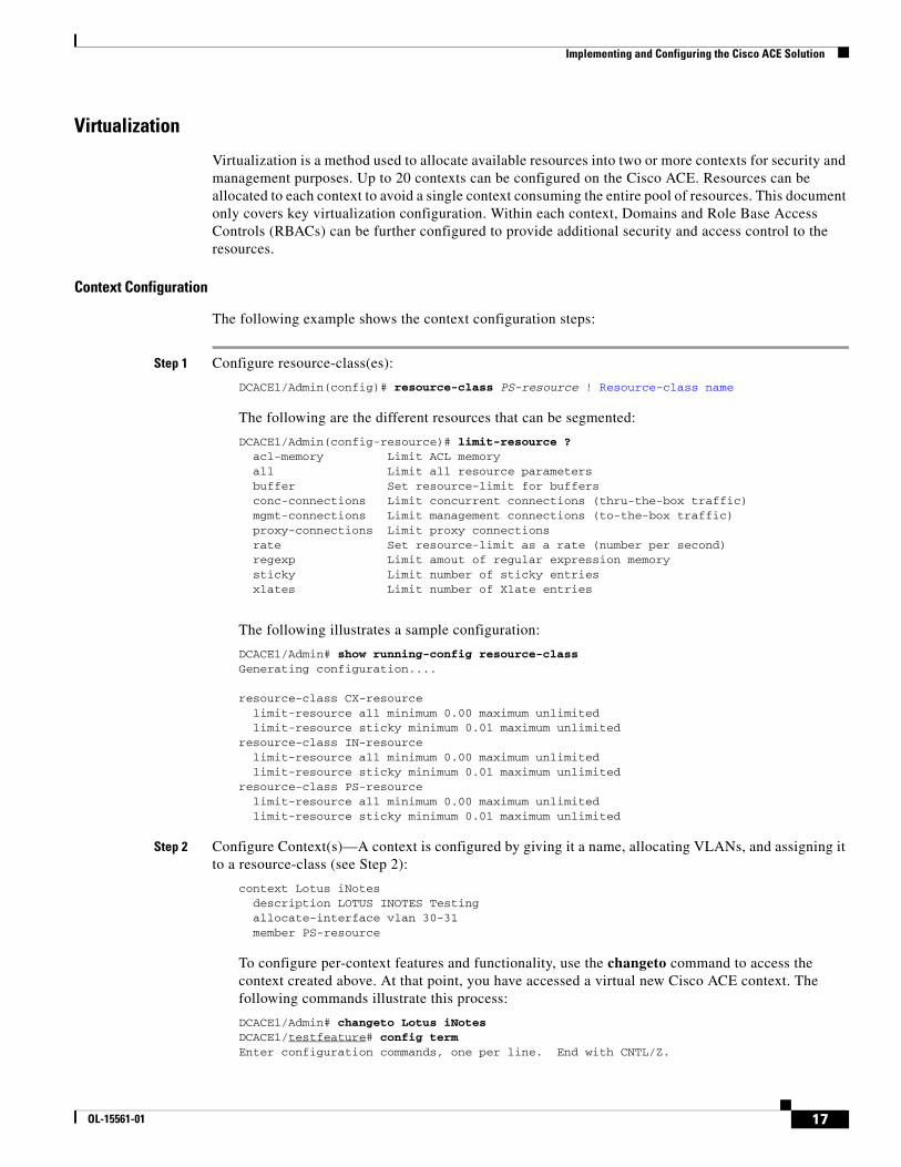
Virtualization is a method used to allocate available resources into two or more contexts for security and management purposes. Up to 20 contexts can be configured on the Cisco ACE. Resources can be allocated to each context to avoid a single context consuming the entire pool of resources. This document only covers key virtualization configuration. Within each context, Domains and Role Base Access Controls (RBACs) can be further configured to provide additional security and access control to the resources.
Context Configuration
The following example shows the context configuration steps:
Step 1 Configure resource-class(es):
DCACE1/Admin(config)# resource-class PS-resource ! Resource-class name
The following are the different resources that can be segmented:
DCACE1/Admin(config-resource)# limit-resource ? acl-memory Limit ACL memory all Limit all resource parameters buffer Set resource-limit for buffers conc-connections Limit concurrent connections (thru-the-box traffic) mgmt-connections Limit management connections (to-the-box traffic) proxy-connections Limit proxy connections rate Set resource-limit as a rate (number per second) regexp Limit amout of regular expression memory sticky Limit number of sticky entries xlates Limit number of Xlate entries
The following illustrates a sample configuration:
DCACE1/Admin# show running-config resource-class Generating configuration....
resource-class CX-resource limit-resource all minimum 0.00 maximum unlimited limit-resource sticky minimum 0.01 maximum unlimitedresource-class IN-resource limit-resource all minimum 0.00 maximum unlimited limit-resource sticky minimum 0.01 maximum unlimitedresource-class PS-resource limit-resource all minimum 0.00 maximum unlimited limit-resource sticky minimum 0.01 maximum unlimited
Step 2 Configure Context(s)—A context is configured by giving it a name, allocating VLANs, and assigning it to a resource-class (see Step 2):
context Lotus iNotes description LOTUS INOTES Testing allocate-interface vlan 30-31 member PS-resource
To configure per-context features and functionality, use the changeto command to access the context created above. At that point, you have accessed a virtual new Cisco ACE context. The following commands illustrate this process:
DCACE1/Admin# changeto Lotus iNotesDCACE1/testfeature# config termEnter configuration commands, one per line. End with CNTL/Z.
17OL-15561-01
Implementing and Configuring the Cisco ACE Solution
For more information on configuring virtualization, visit the following URL: http://preview.cisco.com/en/US/products/ps7027/tsd_products_support_series_home.html
Remote Management Access
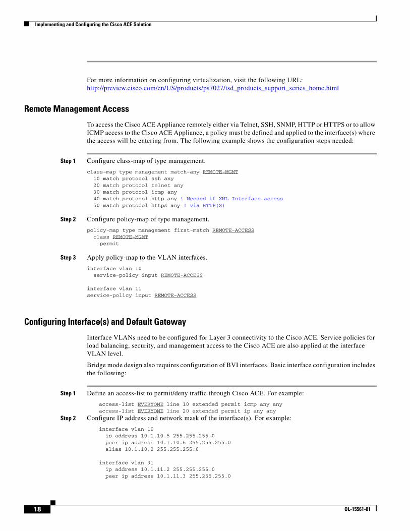
To access the Cisco ACE Appliance remotely either via Telnet, SSH, SNMP, HTTP or HTTPS or to allow ICMP access to the Cisco ACE Appliance, a policy must be defined and applied to the interface(s) where the access will be entering from. The following example shows the configuration steps needed:
Step 1 Configure class-map of type management.
class-map type management match-any REMOTE-MGMT 10 match protocol ssh any 20 match protocol telnet any 30 match protocol icmp any 40 match protocol http any ! Needed if XML Interface access 50 match protocol https any ! via HTTP(S)
Step 2 Configure policy-map of type management.
policy-map type management first-match REMOTE-ACCESS class REMOTE-MGMT permit
Step 3 Apply policy-map to the VLAN interfaces.
interface vlan 10 service-policy input REMOTE-ACCESS interface vlan 11service-policy input REMOTE-ACCESS
Configuring Interface(s) and Default Gateway
Interface VLANs need to be configured for Layer 3 connectivity to the Cisco ACE. Service policies for load balancing, security, and management access to the Cisco ACE are also applied at the interface VLAN level.
Bridge mode design also requires configuration of BVI interfaces. Basic interface configuration includes the following:
Step 1 Define an access-list to permit/deny traffic through Cisco ACE. For example:
access-list EVERYONE line 10 extended permit icmp any anyaccess-list EVERYONE line 20 extended permit ip any any
Step 2 Configure IP address and network mask of the interface(s). For example:
interface vlan 10 ip address 10.1.10.5 255.255.255.0 peer ip address 10.1.10.6 255.255.255.0 alias 10.1.10.2 255.255.255.0 interface vlan 31 ip address 10.1.11.2 255.255.255.0 peer ip address 10.1.11.3 255.255.255.0
18 OL-15561-01
Implementing and Configuring the Cisco ACE Solution
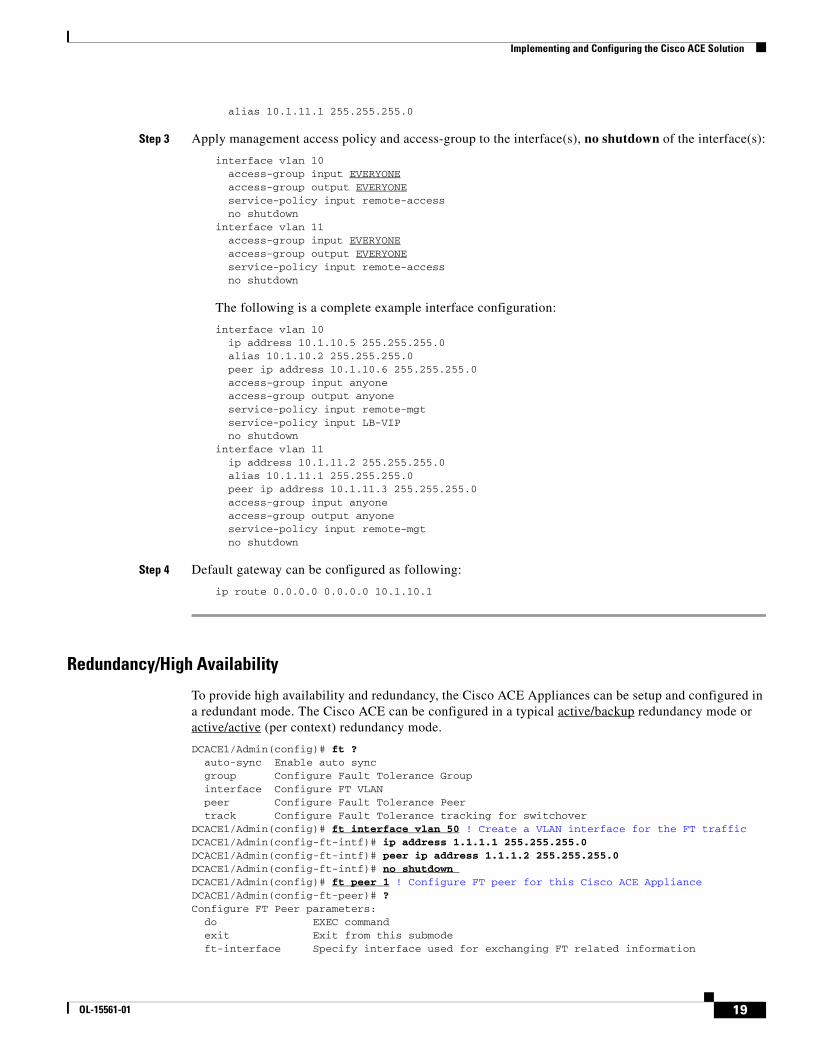
alias 10.1.11.1 255.255.255.0
Step 3 Apply management access policy and access-group to the interface(s), no shutdown of the interface(s):
interface vlan 10 access-group input EVERYONE access-group output EVERYONE service-policy input remote-access no shutdowninterface vlan 11 access-group input EVERYONE access-group output EVERYONE service-policy input remote-access no shutdown
The following is a complete example interface configuration:
interface vlan 10 ip address 10.1.10.5 255.255.255.0 alias 10.1.10.2 255.255.255.0 peer ip address 10.1.10.6 255.255.255.0 access-group input anyone access-group output anyone service-policy input remote-mgt service-policy input LB-VIP no shutdowninterface vlan 11 ip address 10.1.11.2 255.255.255.0 alias 10.1.11.1 255.255.255.0 peer ip address 10.1.11.3 255.255.255.0 access-group input anyone access-group output anyone service-policy input remote-mgt no shutdown
Step 4 Default gateway can be configured as following:
ip route 0.0.0.0 0.0.0.0 10.1.10.1
Redundancy/High Availability
To provide high availability and redundancy, the Cisco ACE Appliances can be setup and configured in a redundant mode. The Cisco ACE can be configured in a typical active/backup redundancy mode or active/active (per context) redundancy mode.
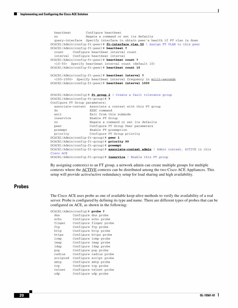
DCACE1/Admin(config)# ft ? auto-sync Enable auto sync group Configure Fault Tolerance Group interface Configure FT VLAN peer Configure Fault Tolerance Peer track Configure Fault Tolerance tracking for switchoverDCACE1/Admin(config)# ft interface vlan 50 ! Create a VLAN interface for the FT trafficDCACE1/Admin(config-ft-intf)# ip address 1.1.1.1 255.255.255.0DCACE1/Admin(config-ft-intf)# peer ip address 1.1.1.2 255.255.255.0DCACE1/Admin(config-ft-intf)# no shutdown DCACE1/Admin(config)# ft peer 1 ! Configure FT peer for this Cisco ACE ApplianceDCACE1/Admin(config-ft-peer)# ?Configure FT Peer parameters: do EXEC command exit Exit from this submode ft-interface Specify interface used for exchanging FT related information
19OL-15561-01
Implementing and Configuring the Cisco ACE Solution
heartbeat Configure heartbeat no Negate a command or set its defaults query-interface Specify interface to obtain peer's health if FT vlan is downDCACE1/Admin(config-ft-peer)# ft-interface vlan 50 ! Assign FT VLAN to this peerDCACE1/Admin(config-ft-peer)# heartbeat ? count Configure heartbeat interval count interval Configure heartbeat intervalDCACE1/Admin(config-ft-peer)# heartbeat count ? <10-50> Specify heartbeat interval count (default 10)DCACE1/Admin(config-ft-peer)# heartbeat count 10
DCACE1/Admin(config-ft-peer)# heartbeat interval ? <100-1000> Specify heartbeat interval frequency in milli-secondsDCACE1/Admin(config-ft-peer)# heartbeat interval 1000
DCACE1/Admin(config)# ft group 2 ! Create a fault tolerance groupDCACE1/Admin(config-ft-group)# ?Configure FT Group parameters: associate-context Associate a context with this FT group do EXEC command exit Exit from this submode inservice Enable FT Group no Negate a command or set its defaults peer Configure FT Group Peer parameters preempt Enable FT preemption priority Configure FT Group priorityDCACE1/Admin(config-ft-group)# peer 1DCACE1/Admin(config-ft-group)# priority 99 DCACE1/Admin(config-ft-group)# preempt DCACE1/Admin(config-ft-group)# associate-context admin ! Admin context, ACTIVE in this Cisco ACE DCACE1/Admin(config-ft-group)# inservice ! Enable this FT group
By assigning context(s) to an FT group, a network admin can create multiple groups for multiple contexts where the ACTIVE contexts can be distributed among the two Cisco ACE Appliances. This setup will provide active/active redundancy setup for load sharing and high availability.
Probes
The Cisco ACE uses probe as one of available keep-alive methods to verify the availability of a real server. Probe is configured by defining its type and name. There are different types of probes that can be configured on ACE, as shown in the following:
DCACE1/Admin(config)# probe ? dns Configure dns probe echo Configure echo probe finger Configure finger probe ftp Configure ftp probe http Configure http probe https Configure https probe icmp Configure icmp probe imap Configure imap probe ldap Configure ldap probe pop Configure pop probe radius Configure radius probe scripted Configure script probe smtp Configure smtp probe tcp Configure tcp probe telnet Configure telnet probe udp Configure udp probe
20 OL-15561-01
Implementing and Configuring the Cisco ACE Solution
Some key timers and parameters need to be tuned when probes are configured. The value for these parameters influences how rapidly ACE (or any load balancer) takes a server out of rotation and brings it back in service. The following parameters need to be tuned for probes of any type (ICMP, UDP, TCP, HTTP, HTTPS, Scripted)
• Faildetect—This refers to how many consecutive failed probes will qualify a server to declared probe failed. ‘Faildetect’ is configured as a counter value. The default value is 3. Generally, faildetect value is left at default value.
• Interval—This refers to how frequently ACE sends probe to a server. Interval is configured in seconds. The default value is 120 seconds. Generally, interval is configured around 5-10 seconds depending upon the applications and size of the environment.
• Passdetect—This configuration determines how ACE will re-probe the server after it has been declared failed. Passdetect variable has two attributes:
– Passdetect count—Refers to how many consecutive successful responses ACE will need to see before declaring a server as OPERATIONAL. The default value is 3. This value can be tuned according to the requirements.
– Passdetect interval—Refers to how many seconds ACE will wait to probe a server after it has been declared failed. The default value is 300 seconds. Generally, the value is changed to a much lower value of 15 to 30 seconds range.
Following additional parameters should be configured for TCP, HTTP, and HTTPS types of probes:
• Open—Refers to the time (in seconds) that ACE will wait to keep a TCP connection open. The default value is 10 seconds. Generally this value is configured close to the interval value.
• Receive—Once a TCP SYN (for a probe) is sent to a server, the value for receive determines how long ACE will wait to receive a reply from the server. This value is configured in seconds and the default value is 10 seconds. Generally it is configured to something equal to or less than the value interval.
• Connection—Determines how ACE closes the connection after it has successfully sent a probe. By default, ACE closes the connection gracefully, meaning, it sends TCP FIN to close the connection. Optionally, ACE can be configured to close the connection with a TCP RESET by configuring ‘connection term forced’.
• Port —TCP/UDP port number on which this probe is sent. Following are the default values for various probes:
– TCP port 80
– UDP port 53
– HTTP port 80
– HTTPS port 443
• Request—This parameter is used to configure HTTP Request method (HEAD or GET) and URL for the probe. The default method is GET and default URL is ‘/’. Generally method and URL are configured according to specific applications. This parameter is only applicable to HTTP/HTTPS probes.
• Expect—This parameter allows ACE to detect two values from the server:
– Expect status – Refers to what HTTP Status Code (or range) to expect from the server. There is no default HTTP return code expected. It has to be configured explicitly.
– Expect regex—A regex can be configured to parse a specific field in the response data.
This parameter is only applicable to HTTP/HTTPS probes.
21OL-15561-01
Implementing and Configuring the Cisco ACE Solution
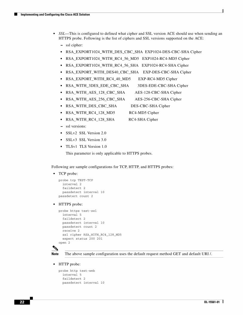
• SSL—This is configured to defined what cipher and SSL version ACE should use when sending an HTTPS probe. Following is the list of ciphers and SSL versions supported on the ACE:
– ssl cipher:
• RSA_EXPORT1024_WITH_DES_CBC_SHA EXP1024-DES-CBC-SHA Cipher
• RSA_EXPORT1024_WITH_RC4_56_MD5 EXP1024-RC4-MD5 Cipher
• RSA_EXPORT1024_WITH_RC4_56_SHA EXP1024-RC4-SHA Cipher
• RSA_EXPORT_WITH_DES40_CBC_SHA EXP-DES-CBC-SHA Cipher
• RSA_EXPORT_WITH_RC4_40_MD5 EXP-RC4-MD5 Cipher
• RSA_WITH_3DES_EDE_CBC_SHA 3DES-EDE-CBC-SHA Cipher
• RSA_WITH_AES_128_CBC_SHA AES-128-CBC-SHA Cipher
• RSA_WITH_AES_256_CBC_SHA AES-256-CBC-SHA Cipher
• RSA_WITH_DES_CBC_SHA DES-CBC-SHA Cipher
• RSA_WITH_RC4_128_MD5 RC4-MD5 Cipher
• RSA_WITH_RC4_128_SHA RC4-SHA Cipher
– ssl versions:
• SSLv2 SSL Version 2.0
• SSLv3 SSL Version 3.0
• TLSv1 TLS Version 1.0
This parameter is only applicable to HTTPS probes.
Following are sample configurations for TCP, HTTP, and HTTPS probes:
• TCP probe:
probe tcp TEST-TCP interval 2 faildetect 2 passdetect interval 10passdetect count 2
• HTTPS probe:
probe https test-ssl interval 5 faildetect 2 passdetect interval 10 passdetect count 2 receive 2 ssl cipher RSA_WITH_RC4_128_MD5 expect status 200 201open 2
Note The above sample configuration uses the default request method GET and default URI /.
• HTTP probe:
probe http test-web interval 5 faildetect 2 passdetect interval 10
22 OL-15561-01
Implementing and Configuring the Cisco ACE Solution
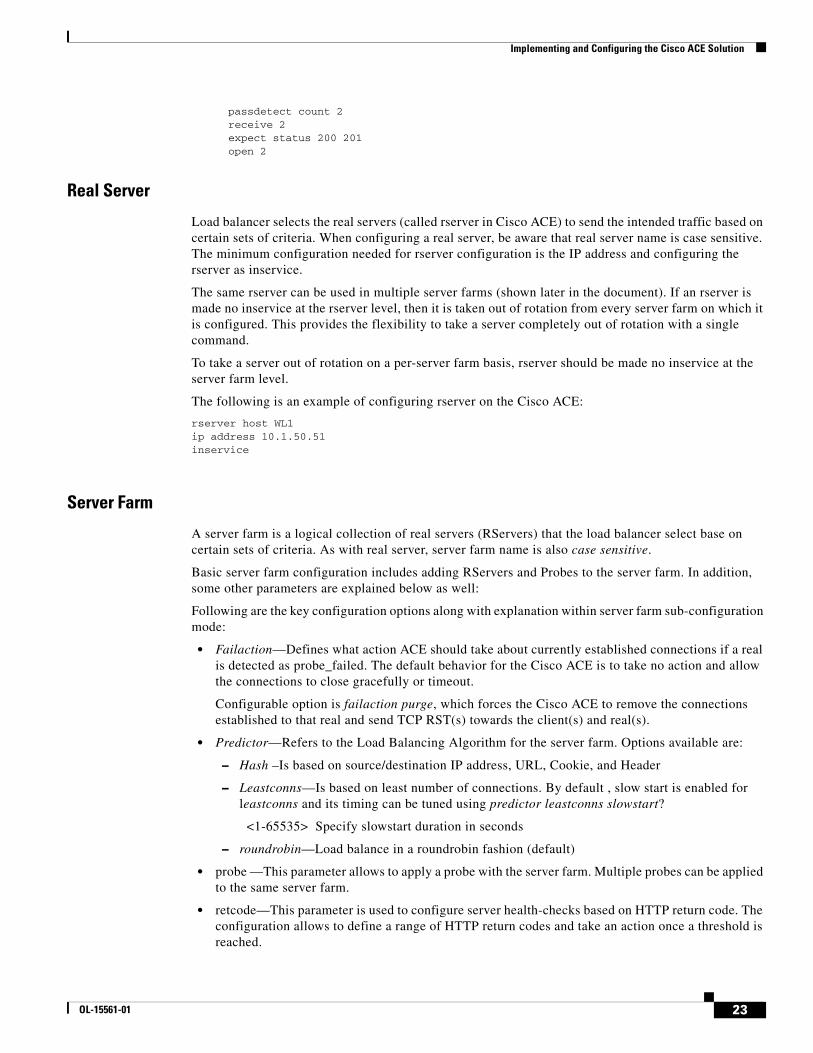
passdetect count 2 receive 2 expect status 200 201 open 2
Real Server
Load balancer selects the real servers (called rserver in Cisco ACE) to send the intended traffic based on certain sets of criteria. When configuring a real server, be aware that real server name is case sensitive. The minimum configuration needed for rserver configuration is the IP address and configuring the rserver as inservice.
The same rserver can be used in multiple server farms (shown later in the document). If an rserver is made no inservice at the rserver level, then it is taken out of rotation from every server farm on which it is configured. This provides the flexibility to take a server completely out of rotation with a single command.
To take a server out of rotation on a per-server farm basis, rserver should be made no inservice at the server farm level.
The following is an example of configuring rserver on the Cisco ACE:
rserver host WL1ip address 10.1.50.51inservice
Server Farm
A server farm is a logical collection of real servers (RServers) that the load balancer select base on certain sets of criteria. As with real server, server farm name is also case sensitive.
Basic server farm configuration includes adding RServers and Probes to the server farm. In addition, some other parameters are explained below as well:
Following are the key configuration options along with explanation within server farm sub-configuration mode:
• Failaction—Defines what action ACE should take about currently established connections if a real is detected as probe_failed. The default behavior for the Cisco ACE is to take no action and allow the connections to close gracefully or timeout.
Configurable option is failaction purge, which forces the Cisco ACE to remove the connections established to that real and send TCP RST(s) towards the client(s) and real(s).
• Predictor—Refers to the Load Balancing Algorithm for the server farm. Options available are:
– Hash –Is based on source/destination IP address, URL, Cookie, and Header
– Leastconns—Is based on least number of connections. By default , slow start is enabled for leastconns and its timing can be tuned using predictor leastconns slowstart?
<1-65535> Specify slowstart duration in seconds
– roundrobin—Load balance in a roundrobin fashion (default)
• probe —This parameter allows to apply a probe with the server farm. Multiple probes can be applied to the same server farm.
• retcode—This parameter is used to configure server health-checks based on HTTP return code. The configuration allows to define a range of HTTP return codes and take an action once a threshold is reached.
23OL-15561-01
Implementing and Configuring the Cisco ACE Solution
retcode <min> <max> check <remove|count|log> <threshold value> resume-service <value in seconds>
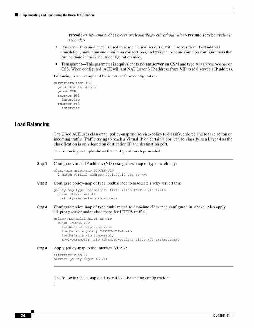
• Rserver—This parameter is used to associate real server(s) with a server farm. Port address translation, maximum and minimum connections, and weight are some common configurations that can be done in rserver sub-configuration mode.
• Transparent—This parameter is equivalent to no nat server on CSM and type transparent-cache on CSS. When configured, ACE will not NAT Layer 3 IP address from VIP to real server’s IP address.
Following is an example of basic server farm configuration:
serverfarm host PS1 predictor leastconns probe TCP rserver PS2 inservice rserver PS3 inservice
Load Balancing
The Cisco ACE uses class-map, policy-map and service-policy to classify, enforce and to take action on incoming traffic. Traffic trying to reach a Virtual IP on certain a port can be classify as a Layer 4 as the classification is only based on destination IP and destination port.
The following example shows the configuration steps needed:
Step 1 Configure virtual IP address (VIP) using class-map of type match-any:
class-map match-any INOTES-VIP 2 match virtual-address 10.1.10.10 tcp eq www
Step 2 Configure policy-map of type loadbalance to associate sticky serverfarm:
policy-map type loadbalance first-match INOTES-VIP-l7slb class class-default sticky-serverfarm app-cookie
Step 3 Configure policy-map of type multi-match to associate class-map configured in above. Also apply ssl-proxy server under class maps for HTTPS traffic.
policy-map multi-match LB-VIP class INOTES-VIP loadbalance vip inservice loadbalance policy INOTES-VIP-l7slb loadbalance vip icmp-reply appl-parameter http advanced-options cisco_avs_parametermap
Step 4 Apply policy-map to the interface VLAN:
interface vlan 10service-policy input LB-VIP
The following is a complete Layer 4 load-balancing configuration:
!
24 OL-15561-01

Implementing and Configuring the Cisco ACE Solution
probe tcp PROBE-TCP interval 2 faildetect 2 passdetect interval 10 passdetect count 2
parameter-map type http cisco_avs_parametermap case-insensitive
ssl-proxy service app-ssl key "rsa1024key.pem" cert "rsa1024cert.pem"
rserver host IN1 ip address 10.1.11.50 inservicerserver host IN2 ip address 10.1.11.51 inservicerserver host IN3 ip address 10.1.11.52
serverfarm host IN1 predictor leastconns probe PROBE-TCP rserver IN1 8090 inservice rserver IN2 8090 inservice rserver IN3 8090 inservice
class-map match-any INOTES-SSL-VIP 2 match virtual-address 10.1.10.10 tcp eq https class-map match-any INOTES-VIP 2 match virtual-address 10.1.10.10 tcp eq www class-map type management match-any remote-access 10 match protocol icmp any 20 match protocol telnet any 30 match protocol ssh any 40 match protocol snmp any 50 match protocol http any 60 match protocol https any
policy-map type management first-match remote-mgt class remote-access permitpolicy-map type loadbalance first-match INOTES-VIP-l7slb class class-default sticky-serverfarm app-cookiepolicy-map multi-match LB-VIP class INOTES-VIP loadbalance vip inservice loadbalance policy INOTES-VIP-l7slb loadbalance vip icmp-reply appl-parameter http advanced-options cisco_avs_parametermap class INOTES-SSL-VIP loadbalance vip inservice loadbalance policy INOTES-VIP-l7slb loadbalance vip icmp-reply appl-parameter http advanced-options cisco_avs_parametermap ssl-proxy server "app-ssl"
25OL-15561-01
Implementing and Configuring the Cisco ACE Solution
interface vlan 10 ip address 10.1.10.5 255.255.255.0 alias 10.1.10.2 255.255.255.0 peer ip address 10.1.10.6 255.255.255.0 access-group input anyone access-group output anyone service-policy input remote-mgt service-policy input LB-VIP no shutdowninterface vlan 11 ip address 10.1.11.2 255.255.255.0 alias 10.1.11.1 255.255.255.0 peer ip address 10.1.11.3 255.255.255.0 access-group input anyone access-group output anyone service-policy input remote-mgt no shutdown
ip route 0.0.0.0 0.0.0.0 10.1.10.1
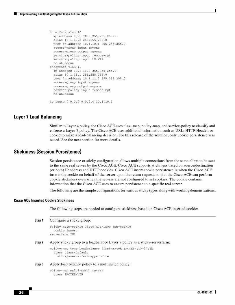
Layer 7 Load Balancing
Similar to Layer 4 policy, the Cisco ACE uses class-map, policy-map, and service-policy to classify and enforce a Layer-7 policy. The Cisco ACE uses additional information such as URL, HTTP Header, or cookie to make a load-balancing decision. For this release of the solution, only cookie persistence was tested. See the next section for more details.
Stickiness (Session Persistence)
Session persistence or sticky configuration allows multiple connections from the same client to be sent to the same real server by the Cisco ACE. Cisco ACE supports stickiness based on source/destination (or both) IP address and HTTP cookies. Cisco ACE insert cookie persistence is when the Cisco ACE inserts the cookie on behalf of the server upon the return request, so that the Cisco ACE can perform cookie stickiness even when the servers are not configured to set cookies. The cookie contains information that the Cisco ACE uses to ensure persistence to a specific real server.
The following are the sample configurations for various sticky types along with working demonstrations.
Cisco ACE Inserted Cookie Stickiness
The following steps are needed to configure stickiness based on Cisco ACE inserted cookie:
Step 1 Configure a sticky group:
sticky http-cookie Cisco ACE-INOT app-cookie cookie insertserverfarm IN1
Step 2 Apply sticky group to a loadbalance Layer 7 policy as a sticky-serverfarm:
policy-map type loadbalance first-match INOTES-VIP-l7slb class class-default sticky-serverfarm app-cookie
Step 3 Apply load balance policy to a multimatch policy:
policy-map multi-match LB-VIP class INOTES-VIP
26 OL-15561-01
Implementing and Configuring the Cisco ACE Solution
loadbalance vip inservice loadbalance policy INOTES-VIP-l7slb loadbalance vip icmp-reply appl-parameter http advanced-options cisco_avs_parametermap
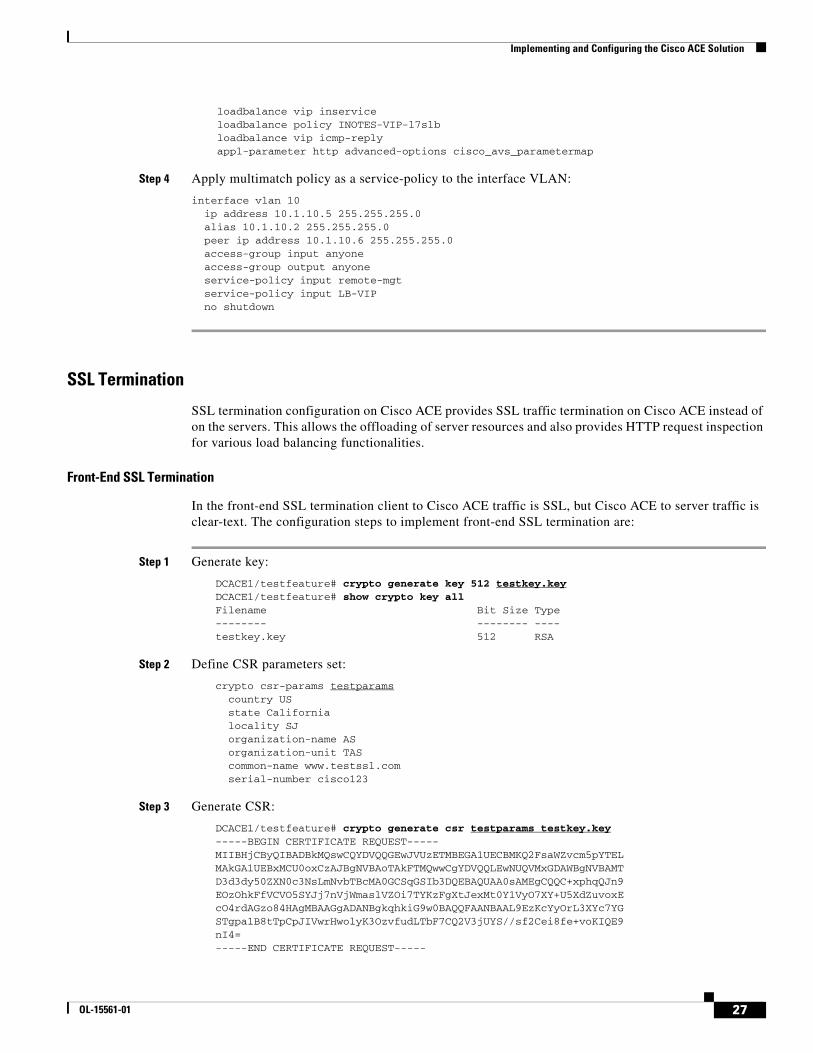
Step 4 Apply multimatch policy as a service-policy to the interface VLAN:
interface vlan 10 ip address 10.1.10.5 255.255.255.0 alias 10.1.10.2 255.255.255.0 peer ip address 10.1.10.6 255.255.255.0 access-group input anyone access-group output anyone service-policy input remote-mgt service-policy input LB-VIP no shutdown
SSL Termination
SSL termination configuration on Cisco ACE provides SSL traffic termination on Cisco ACE instead of on the servers. This allows the offloading of server resources and also provides HTTP request inspection for various load balancing functionalities.
Front-End SSL Termination
In the front-end SSL termination client to Cisco ACE traffic is SSL, but Cisco ACE to server traffic is clear-text. The configuration steps to implement front-end SSL termination are:
Step 1 Generate key:
DCACE1/testfeature# crypto generate key 512 testkey.keyDCACE1/testfeature# show crypto key allFilename Bit Size Type-------- -------- ----testkey.key 512 RSA
Step 2 Define CSR parameters set:
crypto csr-params testparams country US state California locality SJ organization-name AS organization-unit TAS common-name www.testssl.com serial-number cisco123
Step 3 Generate CSR:
DCACE1/testfeature# crypto generate csr testparams testkey.key-----BEGIN CERTIFICATE REQUEST-----MIIBHjCByQIBADBkMQswCQYDVQQGEwJVUzETMBEGA1UECBMKQ2FsaWZvcm5pYTELMAkGA1UEBxMCU0oxCzAJBgNVBAoTAkFTMQwwCgYDVQQLEwNUQVMxGDAWBgNVBAMTD3d3dy50ZXN0c3NsLmNvbTBcMA0GCSqGSIb3DQEBAQUAA0sAMEgCQQC+xphqQJn9EOzOhkFfVCVO5SYJj7nVjWmaslVZOi7TYKzFgXtJexMt0Y1VyO7XY+U5XdZuvoxEcO4rdAGzo84HAgMBAAGgADANBgkqhkiG9w0BAQQFAANBAAL9EzKcYyOrL3XYc7YGSTgpa1B8tTpCpJIVwrHwolyK3OzvfudLTbF7CQ2V3jUYS//sf2Cei8fe+voKIQE9nI4=-----END CERTIFICATE REQUEST-----
27OL-15561-01

Implementing and Configuring the Cisco ACE Solution
Step 4 Obtain certificate:
The SSL certificate can be obtained from various certificate authority (CA) companies like VERISIGN. The following example shows using a Cisco router as a CA.
OS-CA-SERVER#crypto pki server CDN-CA request pkcs10 terminal pem % Enter Base64 encoded or PEM formatted PKCS10 enrollment request.% End with a blank line or "quit" on a line by itself.-----BEGIN CERTIFICATE REQUEST-----MIIBHjCByQIBADBkMQswCQYDVQQGEwJVUzETMBEGA1UECBMKQ2FsaWZvcm5pYTELMAkGA1UEBxMCU0oxCzAJBgNVBAoTAkFTMQwwCgYDVQQLEwNUQVMxGDAWBgNVBAMTD3d3dy50ZXN0c3NsLmNvbTBcMA0GCSqGSIb3DQEBAQUAA0sAMEgCQQC+xphqQJn9EOzOhkFfVCVO5SYJj7nVjWmaslVZOi7TYKzFgXtJexMt0Y1VyO7XY+U5XdZuvoxEcO4rdAGzo84HAgMBAAGgADANBgkqhkiG9w0BAQQFAANBAAL9EzKcYyOrL3XYc7YGSTgpa1B8tTpCpJIVwrHwolyK3OzvfudLTbF7CQ2V3jUYS//sf2Cei8fe+voKIQE9nI4=-----END CERTIFICATE REQUEST-----Quit
% Granted certificate:-----BEGIN CERTIFICATE-----MIIB6TCCAVKgAwIBAgIBCTANBgkqhkiG9w0BAQQFADARMQ8wDQYDVQQDEwZDRE4tQ0EwHhcNMDYwNDI2MTgxNjQzWhcNMDcwNDI2MTgxNjQzWjBkMQswCQYDVQQGEwJVUzETMBEGA1UECBMKQ2FsaWZvcm5pYTELMAkGA1UEBxMCU0oxCzAJBgNVBAoTAkFTMQwwCgYDVQQLEwNUQVMxGDAWBgNVBAMTD3d3dy50ZXN0c3NsLmNvbTBcMA0GCSqGSIb3DQEBAQUAA0sAMEgCQQC+xphqQJn9EOzOhkFfVCVO5SYJj7nVjWmaslVZOi7TYKzFgXtJexMt0Y1VyO7XY+U5XdZuvoxEcO4rdAGzo84HAgMBAAGjQjBAMB8GA1UdIwQYMBaAFNKc5JGHmabT17tofs9CUD8mxVURMB0GA1UdDgQWBBQAL2ptyfN85SoVNdEiGRav8nI8lTANBgkqhkiG9w0BAQQFAAOBgQAUHyfbs+aMapSEFXmdlKPh8F67gGuYBdyWxmXjR7KVErDxde+4UqJCkNP4R2m11g30j6UveG2wLiP7C4IZHzGfFXUbzdPhaZ1838qgZlFn+lXPtCrayto1PitWeuPbCwLTxmE2vWWLw6lwEzguVbF+6t0nmLAkyiYsuz/MOiql/g==-----END CERTIFICATE-----
IOS-CA-SERVER#
Step 5 Import cert on the Cisco ACE:
DCACE1/testfeature# crypto import terminal testcert.pemPlease enter PEM formatted data. End with "quit" on a new line. -----BEGIN CERTIFICATE----- MIIB6TCCAVKgAwIBAgIBCTANBgkqhkiG9w0BAQQFADARMQ8wDQYDVQQDEwZDRE4t Q0EwHhcNMDYwNDI2MTgxNjQzWhcNMDcwNDI2MTgxNjQzWjBkMQswCQYDVQQGEwJV UzETMBEGA1UECBMKQ2FsaWZvcm5pYTELMAkGA1UEBxMCU0oxCzAJBgNVBAoTAkFT MQwwCgYDVQQLEwNUQVMxGDAWBgNVBAMTD3d3dy50ZXN0c3NsLmNvbTBcMA0GCSqG SIb3DQEBAQUAA0sAMEgCQQC+xphqQJn9EOzOhkFfVCVO5SYJj7nVjWmaslVZOi7T YKzFgXtJexMt0Y1VyO7XY+U5XdZuvoxEcO4rdAGzo84HAgMBAAGjQjBAMB8GA1Ud IwQYMBaAFNKc5JGHmabT17tofs9CUD8mxVURMB0GA1UdDgQWBBQAL2ptyfN85SoV NdEiGRav8nI8lTANBgkqhkiG9w0BAQQFAAOBgQAUHyfbs+aMapSEFXmdlKPh8F67 gGuYBdyWxmXjR7KVErDxde+4UqJCkNP4R2m11g30j6UveG2wLiP7C4IZHzGfFXUb zdPhaZ1838qgZlFn+lXPtCrayto1PitWeuPbCwLTxmE2vWWLw6lwEzguVbF+6t0n mLAkyiYsuz/MOiql/g== -----END CERTIFICATE----- quit
Step 6 Validate certificate using key:
DCACE1/testfeature# crypto verify testkey.key testcert.pemKeypair in testkey.key matches certificate in testcert.pem.
Step 7 Configure SSL parameters and SSL proxy service:
a. SSL parameter configuration:
28 OL-15561-01
Implementing and Configuring the Cisco ACE Solution
parameter-map type ssl sslparams cipher RSA_WITH_RC4_128_MD5 version SSL3
b. SSL proxy service configuration:
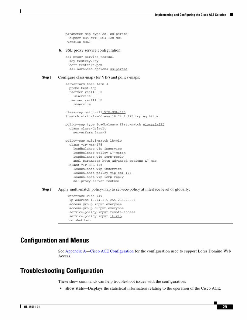
ssl-proxy service testssl key testkey.key cert testcert.pem ssl advanced-options sslparams
Step 8 Configure class-map (for VIP) and policy-maps:
serverfarm host farm-3 probe test-tcp rserver real40 80 inservice rserver real41 80 inservice
class-map match-all VIP-SSL-1752 match virtual-address 10.74.1.175 tcp eq https
policy-map type loadbalance first-match vip-ssl-175 class class-default serverfarm farm-3
policy-map multi-match lb-vip class VIP-WEB-175 loadbalance vip inservice loadbalance policy L7-match loadbalance vip icmp-reply appl-parameter http advanced-options L7-map class VIP-SSL-175 loadbalance vip inservice loadbalance policy vip-ssl-175 loadbalance vip icmp-reply ssl-proxy server testssl
Step 9 Apply multi-match policy-map to service-policy at interface level or globally:
interface vlan 749 ip address 10.74.1.5 255.255.255.0 access-group input everyone access-group output everyone service-policy input remote-access service-policy input lb-vip no shutdown
Configuration and MenusSee Appendix A—Cisco ACE Configuration for the configuration used to support Lotus Domino Web Access.
Troubleshooting ConfigurationThese show commands can help troubleshoot issues with the configuration:
• show stats—Displays the statistical information relating to the operation of the Cisco ACE.
29OL-15561-01
Implementing and Configuring the Cisco WAAS Solution
• show service-policy policy_name—Displays the statistics for service policies enabled globally within a context or on a specific interface.
• show serverfarm name detail—Displays the summary or detailed server-farm statistics.
• show rserver rserver_name detail—Displays the summary or detailed statistics for a named real server or for all real servers.
• show probe—Displays the probe information including script probes.
• show arp—Displays the current active IP address-to-MAC address mapping in the ARP table, statistics, or inspection or timeout configuration.
• show arp statistics—Displays the ARP statistics for all VLAN interfaces.
• show context—Verifies the auto-sync configuration of all contexts.
• show ft group status—Verifies FT status of all configured context in the Cisco ACE.
• show ft peer detail—Verifies the state of FT peering.
• show resource usage—Displays the resource usage for each context.
• show np NP_number—Displays the hardware information stored on the three network processors.
Configuration Rollback
Configuration rollback allows the administrator to revert back to a previous configuration when the new configuration does not work.
Step 1 Create a configuration checkpoint:
ACE_1/testfeature# checkpoint create name
Step 2 Rollback to the checkpoint defined in Step 1:
ACE_1/testfeature# show checkpoint allACE_1/testfeature# checkpoint rollback config-05-09-06
Implementing and Configuring the Cisco WAAS Solution
Implementation
Implementation Overview
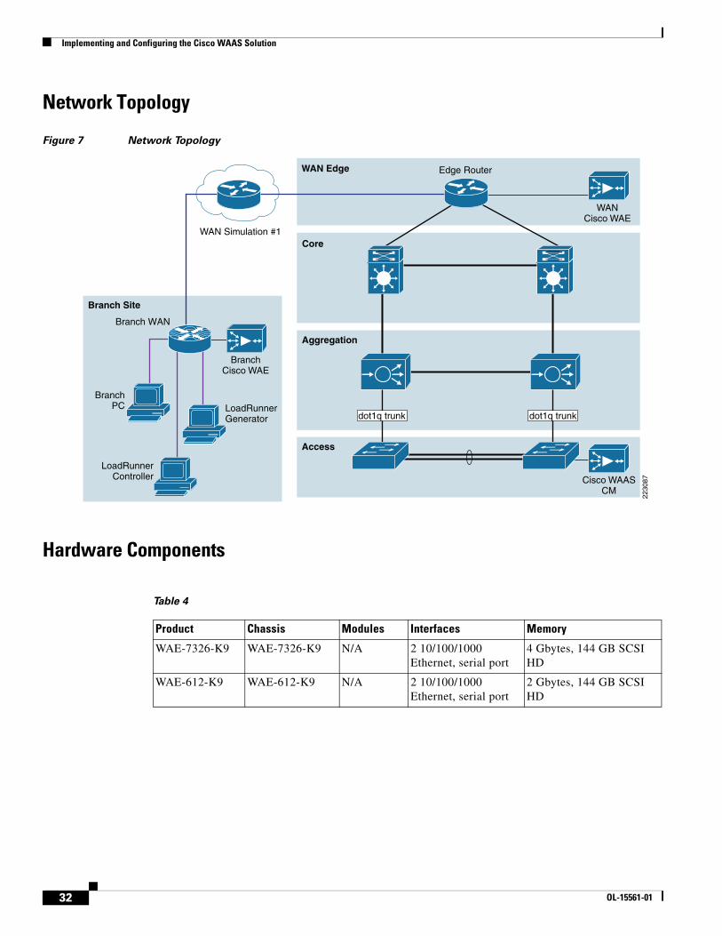
The Cisco WAAS solution requires a minimum of three Cisco Wide Area Application Engine (WAE) appliances to auto-discover and deliver applicable application optimizations. One Cisco WAE is placed in the enterprise data center and the other at the branch site. The enterprise data center Cisco WAE is placed on the WAN edge connected to the WAN router. The third Cisco WAE is used for the Central Manager. The architecture offloads the Cisco WAE device from the local branch router and leverages the available ports on a local switch. This design provides scalability and availability for the solution.
30 OL-15561-01
Implementing and Configuring the Cisco WAAS Solution
Implemented Features
The Cisco WAAS technology requires the efficient and predictable interception of application traffic to produce results. It is critical that the Cisco WAE device see the entire TCP conversation. At the WAN edge, Cisco routers support the following four methods of traffic interception:
• Policy-based routing (PBR)
• Web Cache Communications Protocol (WCCP) v2
• Service policy with Cisco ACE
• Inline hardware
WCCPv2 is the most common method used in the remote branch environment; therefore, WCCPv2 has been leveraged for this solution.
Note Cisco WAEs “out of box” have a standard set of application variables and ports that are defined for optimization. In this solution no changes need to be made to the standard default configuration of the Cisco WAEs.
What was Not Implemented
The consolidated branch model was not implemented in this solution. This model uses an integrated services router, providing a comprehensive solution within a single platform. The consolidated branch provides less scalability and should be considered for use with a branch with small number of users.
31OL-15561-01
Implementing and Configuring the Cisco WAAS Solution
Network Topology
Figure 7 Network Topology
Hardware Components
WAN Simulation #1
BranchPC
Access
Aggregation
WAN Edge
Core
Branch Site
2230
87
Edge Router
Branch WAN
WANCisco WAE
LoadRunnerGenerator
LoadRunnerController
BranchCisco WAE
Cisco WAASCM
dot1q trunk dot1q trunk
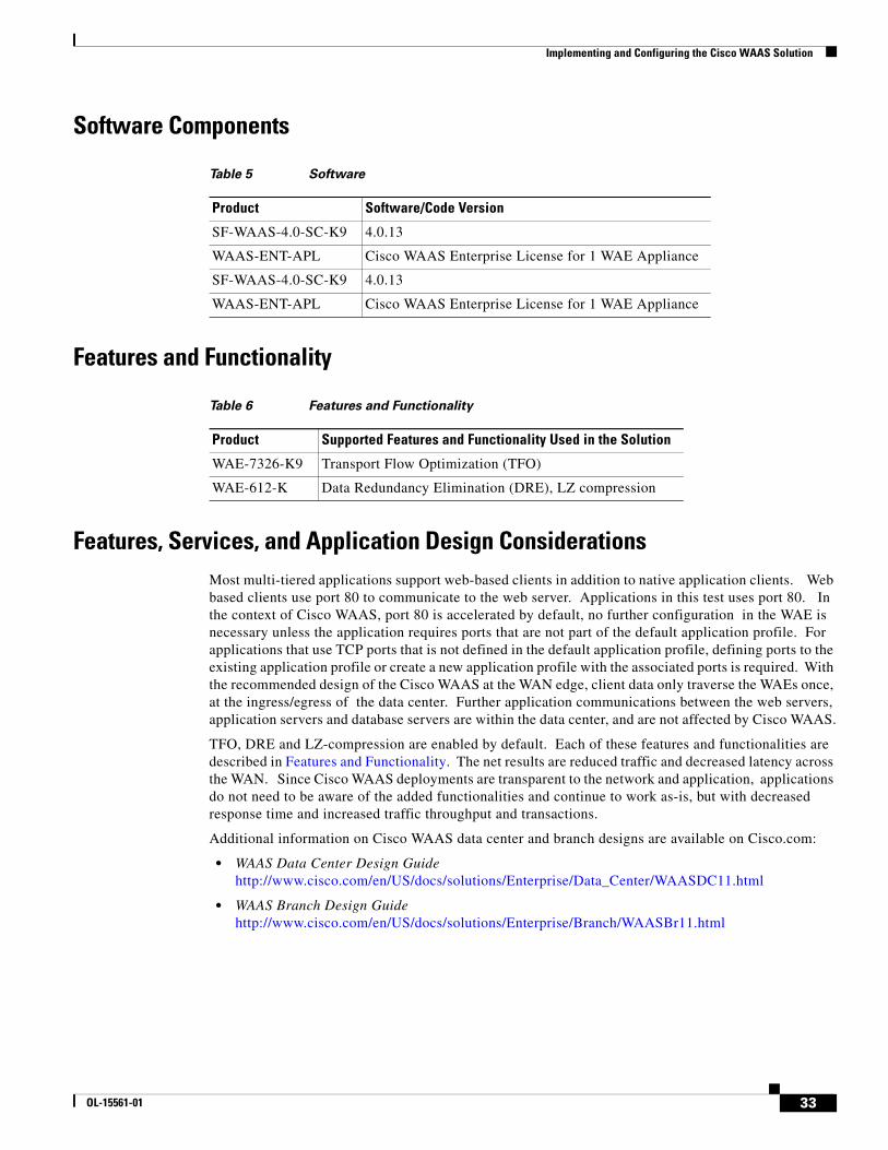
Table 4
Product Chassis Modules Interfaces Memory
WAE-7326-K9 WAE-7326-K9 N/A 2 10/100/1000 Ethernet, serial port
4 Gbytes, 144 GB SCSI HD
WAE-612-K9 WAE-612-K9 N/A 2 10/100/1000 Ethernet, serial port
2 Gbytes, 144 GB SCSI HD
32 OL-15561-01
Implementing and Configuring the Cisco WAAS Solution
Software Components
Features and Functionality
Features, Services, and Application Design ConsiderationsMost multi-tiered applications support web-based clients in addition to native application clients. Web based clients use port 80 to communicate to the web server. Applications in this test uses port 80. In the context of Cisco WAAS, port 80 is accelerated by default, no further configuration in the WAE is necessary unless the application requires ports that are not part of the default application profile. For applications that use TCP ports that is not defined in the default application profile, defining ports to the existing application profile or create a new application profile with the associated ports is required. With the recommended design of the Cisco WAAS at the WAN edge, client data only traverse the WAEs once, at the ingress/egress of the data center. Further application communications between the web servers, application servers and database servers are within the data center, and are not affected by Cisco WAAS.
TFO, DRE and LZ-compression are enabled by default. Each of these features and functionalities are described in Features and Functionality. The net results are reduced traffic and decreased latency across the WAN. Since Cisco WAAS deployments are transparent to the network and application, applications do not need to be aware of the added functionalities and continue to work as-is, but with decreased response time and increased traffic throughput and transactions.
Additional information on Cisco WAAS data center and branch designs are available on Cisco.com:
• WAAS Data Center Design Guide http://www.cisco.com/en/US/docs/solutions/Enterprise/Data_Center/WAASDC11.html
• WAAS Branch Design Guidehttp://www.cisco.com/en/US/docs/solutions/Enterprise/Branch/WAASBr11.html
Table 5 Software
Product Software/Code Version
SF-WAAS-4.0-SC-K9 4.0.13
WAAS-ENT-APL Cisco WAAS Enterprise License for 1 WAE Appliance
SF-WAAS-4.0-SC-K9 4.0.13
WAAS-ENT-APL Cisco WAAS Enterprise License for 1 WAE Appliance
Table 6 Features and Functionality
Product Supported Features and Functionality Used in the Solution
WAE-7326-K9 Transport Flow Optimization (TFO)
WAE-612-K Data Redundancy Elimination (DRE), LZ compression
33OL-15561-01
Implementing and Configuring the Cisco WAAS Solution
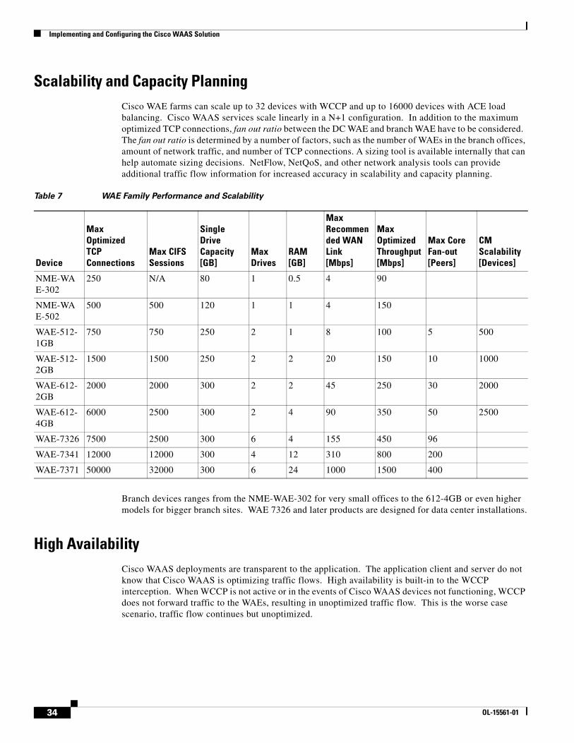
Scalability and Capacity Planning Cisco WAE farms can scale up to 32 devices with WCCP and up to 16000 devices with ACE load balancing. Cisco WAAS services scale linearly in a N+1 configuration. In addition to the maximum optimized TCP connections, fan out ratio between the DC WAE and branch WAE have to be considered. The fan out ratio is determined by a number of factors, such as the number of WAEs in the branch offices, amount of network traffic, and number of TCP connections. A sizing tool is available internally that can help automate sizing decisions. NetFlow, NetQoS, and other network analysis tools can provide additional traffic flow information for increased accuracy in scalability and capacity planning.
Branch devices ranges from the NME-WAE-302 for very small offices to the 612-4GB or even higher models for bigger branch sites. WAE 7326 and later products are designed for data center installations.
High AvailabilityCisco WAAS deployments are transparent to the application. The application client and server do not know that Cisco WAAS is optimizing traffic flows. High availability is built-in to the WCCP interception. When WCCP is not active or in the events of Cisco WAAS devices not functioning, WCCP does not forward traffic to the WAEs, resulting in unoptimized traffic flow. This is the worse case scenario, traffic flow continues but unoptimized.
Table 7 WAE Family Performance and Scalability
Device
Max Optimized TCP Connections
Max CIFS Sessions
Single Drive Capacity [GB]
Max Drives
RAM [GB]
Max Recommended WAN Link [Mbps]
Max Optimized Throughput [Mbps]
Max Core Fan-out [Peers]
CM Scalability [Devices]
NME-WAE-302
250 N/A 80 1 0.5 4 90
NME-WAE-502
500 500 120 1 1 4 150
WAE-512-1GB
750 750 250 2 1 8 100 5 500
WAE-512-2GB
1500 1500 250 2 2 20 150 10 1000
WAE-612-2GB
2000 2000 300 2 2 45 250 30 2000
WAE-612-4GB
6000 2500 300 2 4 90 350 50 2500
WAE-7326 7500 2500 300 6 4 155 450 96
WAE-7341 12000 12000 300 4 12 310 800 200
WAE-7371 50000 32000 300 6 24 1000 1500 400
34 OL-15561-01
Implementing and Configuring the Cisco WAAS Solution
Device High Availability
The WAEs have many built-in high availability features. The disk subsystem is recommended to be configured with RAID 1 protection. RAID 1 is mandatory when two or more drives are installed in the WAE. With RAID 1, failure of the physical drive does not affect normal operations. Failed disks can be replaced during planned downtime. Multiple network interfaces are available. Standby interfaces can be configured for interface failover. A standby interface group guards against network interface failure on the WAE and switch. When connected to separate switches in active/standby mode, the standby interface protects the WAE from switch failure.
N+1 Availability
WAEs and the network provide additional high availability (HA) capabilities. Routers can be configured redundantly providing HSRP or GLBP services. WAEs can configured in a N+1 configuration. N+1 configuration not only provide scalability but availability as well. This design calls for N number of WAEs for a specific workload, then add a standby WAE. Since the workload always distributes evenly among the WAEs, the standby WAE is utilized, reducing overall workload. In the event that a WAE fails, the rest of WAEs can resume normal workload.
Configuration Task ListsInformation required prior to configuration of the equipment
Branch and Data Center Router
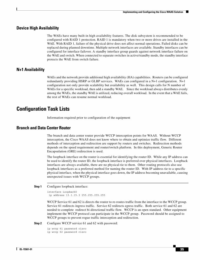
The branch and data center router provide WCCP interception points for WAAS. Without WCCP interception, the Cisco WAAS does not know where to obtain and optimize traffic flow. Different methods of interception and redirection are support by routers and switches. Redirection methods depends on the speed requirement and router/switch platform. In this deployment, Generic Router Encapsulation (GRE) redirection is used.
The loopback interface on the router is essential for identifying the router ID. While any IP address can be used to identify the router ID, the loopback interface is preferred over physical interfaces. Loopback interfaces are always available, there are no physical-tie to them. Other routing protocols also use loopback interfaces as a preferred method for naming the router ID. With IP address tie to a specific physical interface, when the physical interface goes down, the IP address becoming unavailable, causing unexpected issues with WCCP groups.
Step 1 Configure loopback interface:
interface Loopback0 ip address 13.1.15.3 255.255.255.255
WCCP Service 61 and 62 is directs the router to re-routes traffic from the interface to the WCCP group. Service 61 redirects ingress traffic. Service 62 redirects egress traffic. Both service 61 and 62 are needed to complete redirect bi-directional traffic flow. WCCP is an open standard. Other equipment implement the WCCP protocol can participate in the WCCP group. Password should be assigned to WCCP groups to prevent rogue traffic interception and redirection.
Step 2 Configure WCCP service 61 and 62 with password:
ip wccp 61 password ciscoip wccp 62 password cisco
35OL-15561-01
Implementing and Configuring the Cisco WAAS Solution
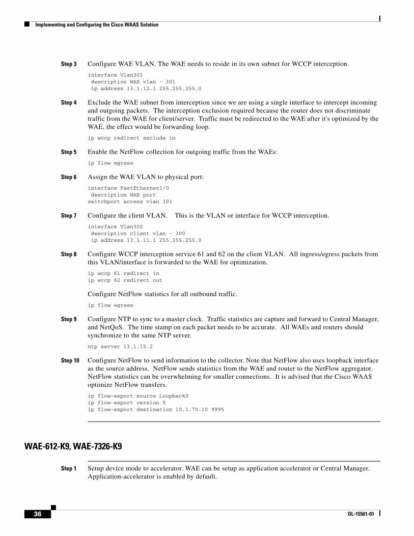
Step 3 Configure WAE VLAN. The WAE needs to reside in its own subnet for WCCP interception.
interface Vlan301 description WAE vlan - 301 ip address 13.1.12.1 255.255.255.0
Step 4 Exclude the WAE subnet from interception since we are using a single interface to intercept incoming and outgoing packets. The interception exclusion required because the router does not discriminate traffic from the WAE for client/server. Traffic must be redirected to the WAE after it's optimized by the WAE, the effect would be forwarding loop.
ip wccp redirect exclude in
Step 5 Enable the NetFlow collection for outgoing traffic from the WAEs:
ip flow egress
Step 6 Assign the WAE VLAN to physical port:
interface FastEthernet1/0 description WAE portswitchport access vlan 301
Step 7 Configure the client VLAN. This is the VLAN or interface for WCCP interception.
interface Vlan300 description client vlan - 300 ip address 13.1.11.1 255.255.255.0
Step 8 Configure WCCP interception service 61 and 62 on the client VLAN. All ingress/egress packets from this VLAN/interface is forwarded to the WAE for optimization.
ip wccp 61 redirect inip wccp 62 redirect out
Configure NetFlow statistics for all outbound traffic.
ip flow egress
Step 9 Configure NTP to sync to a master clock. Traffic statistics are capture and forward to Central Manager, and NetQoS. The time stamp on each packet needs to be accurate. All WAEs and routers should synchronize to the same NTP server.
ntp server 13.1.15.2
Step 10 Configure NetFlow to send information to the collector. Note that NetFlow also uses loopback interface as the source address. NetFlow sends statistics from the WAE and router to the NetFlow aggregator. NetFlow statistics can be overwhelming for smaller connections. It is advised that the Cisco WAAS optimize NetFlow transfers.
ip flow-export source Loopback0ip flow-export version 5ip flow-export destination 10.1.70.10 9995
WAE-612-K9, WAE-7326-K9
Step 1 Setup device mode to accelerator. WAE can be setup as application accelerator or Central Manager. Application-accelerator is enabled by default.
36 OL-15561-01
Implementing and Configuring the Cisco WAAS Solution
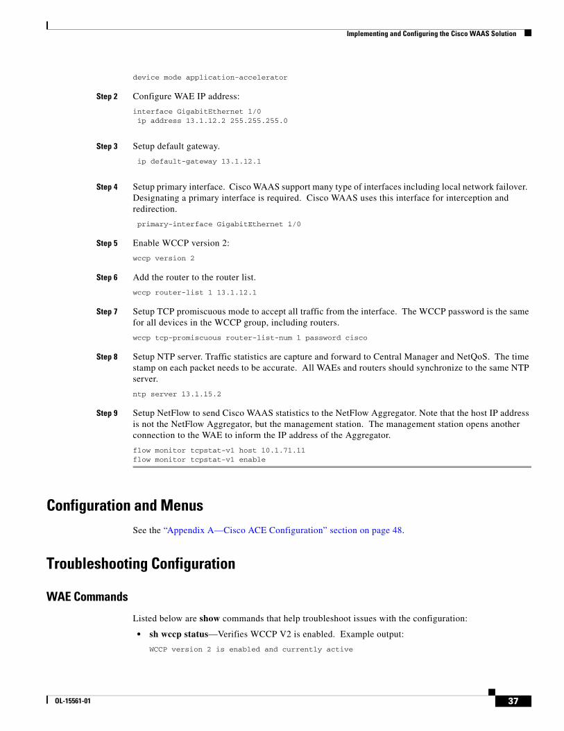
device mode application-accelerator
Step 2 Configure WAE IP address:
interface GigabitEthernet 1/0 ip address 13.1.12.2 255.255.255.0
Step 3 Setup default gateway.
ip default-gateway 13.1.12.1
Step 4 Setup primary interface. Cisco WAAS support many type of interfaces including local network failover. Designating a primary interface is required. Cisco WAAS uses this interface for interception and redirection.
primary-interface GigabitEthernet 1/0
Step 5 Enable WCCP version 2:
wccp version 2
Step 6 Add the router to the router list.
wccp router-list 1 13.1.12.1
Step 7 Setup TCP promiscuous mode to accept all traffic from the interface. The WCCP password is the same for all devices in the WCCP group, including routers.
wccp tcp-promiscuous router-list-num 1 password cisco
Step 8 Setup NTP server. Traffic statistics are capture and forward to Central Manager and NetQoS. The time stamp on each packet needs to be accurate. All WAEs and routers should synchronize to the same NTP server.
ntp server 13.1.15.2
Step 9 Setup NetFlow to send Cisco WAAS statistics to the NetFlow Aggregator. Note that the host IP address is not the NetFlow Aggregator, but the management station. The management station opens another connection to the WAE to inform the IP address of the Aggregator.
flow monitor tcpstat-v1 host 10.1.71.11flow monitor tcpstat-v1 enable
Configuration and MenusSee the “Appendix A—Cisco ACE Configuration” section on page 48.
Troubleshooting Configuration
WAE Commands
Listed below are show commands that help troubleshoot issues with the configuration:
• sh wccp status—Verifies WCCP V2 is enabled. Example output:
WCCP version 2 is enabled and currently active
37OL-15561-01
Implementing and Configuring the Cisco WAAS Solution
• sh wccp services—Verifies WCCP service 61 and 62 is active. Service 61 and 62 must be active. Example output:
Services configured on this File Engine TCP Promiscuous 61 TCP Promiscuous 62
• sh wccp routers—Verifies router can see the WAE. Note that the router ID is the router loopback address. Sent To is the router interface on the WAE VLAN. All routers are defined and visible on the WAE. Example output:
Router Information for Service: TCP Promiscuous 61 Routers Configured and Seeing this File Engine(1) Router Id Sent To Recv ID 13.1.15.3 13.1.12.1 00040E89 Routers not Seeing this File Engine -NONE- Routers Notified of but not Configured -NONE- Multicast Addresses Configured -NONE-
Router Information for Service: TCP Promiscuous 62 Routers Configured and Seeing this File Engine(1) Router Id Sent To Recv ID 13.1.15.3 13.1.12.1 00040E78 Routers not Seeing this File Engine -NONE- Routers Notified of but not Configured -NONE- Multicast Addresses Configured -NONE-
• sh tfo connections summary—Verifies Cisco WAAS clients are using Cisco WAAS for connectivity. Show tfo connections show all optimize path in the WAE. The policy field indicates which optimization method is active for the specified link. F shows the link is fully optimized, that includes DRE, TFO (shown as TCP Optimization), and LZ compression. Pass-through connections are connections that are not optimized at all. Example output:
Optimized Connection ListPolicy summary order: Our's, Peer's, Negotiated, AppliedF: Full optimization, D: DRE only, L: LZ Compression, T: TCP Optimization
Local-IP:Port Remote-IP:Port ConId PeerId Policy13.1.11.3:49520 13.1.40.41:80 43357 00:14:5e:ac:3a:47 F,F,F,F13.1.11.2:9146 13.1.40.41:80 55532 00:14:5e:ac:3a:47 F,F,F,F
Pass-Through ConnectionsLocal-IP:Port Remote-IP:Port Conn Type13.1.42.54:445 13.1.11.2:5401 PT In Progress13.1.12.2:42708 13.1.50.6:7878 Internal Client13.1.41.58:139 172.28.210.61:5425 PT In Progress13.1.40.53:445 13.1.11.2:5491 PT In Progress
• sh statistics dre—Checks DRE usage. There are two sections of the statistics. One is encode, traffic coming in to the WAE from the client/server. The WAE needs to compress the incoming traffic with LZ compression then apply DRE. Another is the decode, traffic is coming from the peering WAE, DRE lookup is performed and traffic uncompressed. These statistics are useful for finding compressibility of the data. Example output:
Cache: Status: Usable, Oldest Data (age): 33d
38 OL-15561-01
Implementing and Configuring the Cisco WAAS Solution
Total usable disk size: 118876 MB, Used: 24.19% Hash table RAM size: 475 MB, Used: 18.00%
Connections: Total (cumulative): 41038 Active: 2
Encode: Overall: msg: 4058742, in: 606 MB, out: 189 MB, ratio: 68.76% DRE: msg: 4037944, in: 602 MB, out: 484 MB, ratio: 19.56%DRE Bypass: msg: 20798, in: 3791 KB LZ: msg: 1469108, in: 431 MB, out: 131 MB, ratio: 69.40% LZ Bypass: msg: 2589634, in: 58894 KB Avg latency: 0.180 ms Message size distribution: 0-1K=99% 1K-5K=0% 5K-15K=0% 15K-25K=0% 25K-40K=0% >40K=0%Decode: Overall: msg: 5114308, in: 13123 MB, out: 15909 MB, ratio: 17.51% DRE: msg: 5086542, in: 13342 MB, out: 15908 MB, ratio: 16.13%DRE Bypass: msg: 27766, in: 505 KB LZ: msg: 4490694, in: 11386 MB, out: 11605 MB, ratio: 1.89% LZ Bypass: msg: 623614, in: 1737 MB Avg latency: 0.244 ms Message size distribution: 0-1K=20% 1K-5K=74% 5K-15K=3% 15K-25K=0% 25K-40K=0% >40K=0%
Router Commands
• sh ip wccp 61—Verifies WCCP service 61 and 62 is active. This command shows global WCCP information and how the packets are redirected. Redirect and group access-list issues can easier troubleshoot with this output. Service 62 should also check with the sh ip wccp 62 command. Example output:
Global WCCP information: Router information: Router Identifier: 13.1.15.3 Protocol Version: 2.0
Service Identifier: 61 Number of Service Group Clients: 1 Number of Service Group Routers: 1 Total Packets s/w Redirected: 60434039 Process: 435 Fast: 0 CEF: 60433604 Redirect access-list: -none- Total Packets Denied Redirect: 0 Total Packets Unassigned: 414 Group access-list: -none- Total Messages Denied to Group: 0 Total Authentication failures: 9 Total Bypassed Packets Received: 0
• sh ip wccp 61 detail—Checks WCCP client hash or Layer 2 assignments. This command also check the status of the WCCP client, namely the WAEs. sh ip wccp 61 shows global WCCP information, this command shows detailed WCCP client information. Hashing assignments (WAE bucket assignments), client ID, and client status are found on this output. Example output:
WCCP Client information: WCCP Client ID: 13.1.12.2 Protocol Version: 2.0 State: Usable Initial Hash Info: FFFFFFFFFFFFFFFFFFFFFFFFFFFFFFFF
39OL-15561-01
Implementing and Configuring the Cisco WAAS Solution
FFFFFFFFFFFFFFFFFFFFFFFFFFFFFFFF Assigned Hash Info: FFFFFFFFFFFFFFFFFFFFFFFFFFFFFFFF FFFFFFFFFFFFFFFFFFFFFFFFFFFFFFFF Hash Allotment: 256 (100.00%) Packets s/w Redirected: 15107709 Connect Time: 4d05h Bypassed Packets Process: 0 Fast: 0 CEF: 0 Errors: 0
• sh ip wccp interface detail—Verifies which interface has WCCP configured. Identify all interfaces within a router or switch that has WCCP configured with ingress or egress for exclude-in redirection. Another way to get this information is from sh run and look through each interface. Example output:
WCCP interface configuration details: Vlan300 Output services: 1 Static: None Dynamic: 062 Input services: 1 Static: None Dynamic: 061 Mcast services: 0 Exclude In: FALSE
Vlan301 Output services: 0 Input services: 0 Mcast services: 0 Exclude In: TRUE
• sh ip wccp 61 view—Verifies WCCP group membership. Need to check service 62 as well. Example output:
WCCP Routers Informed of: 13.1.15.3WCCP Clients Visible: 13.1.12.2WCCP Clients NOT Visible: -none-
Results and ConclusionsFigure 8 provides the amount data volume transversing the 1.544 Mbps WAN link with and without the Cisco WAAS device that was observed during in a 30-minute cycle with 40 users performing site navigation on Lotus Domino Web Access application.. The Cisco WAAS device reduces the amount of unnecessary data volume that will transverse the WAN by locally caching data and using compression algorithms on the data the must transverse the WAN. As seen Figure 8, the Cisco WAAS enabled network becomes more efficient as less data must transverse the WAN.
40 OL-15561-01
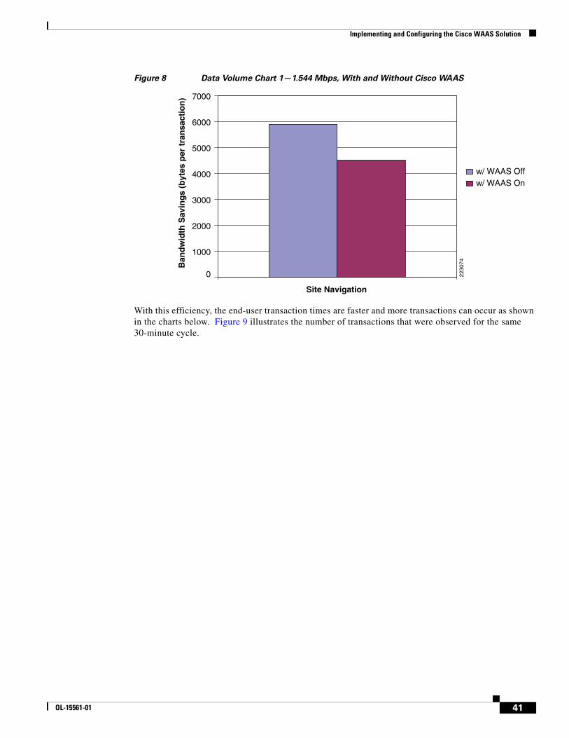
Implementing and Configuring the Cisco WAAS Solution
Figure 8 Data Volume Chart 1—1.544 Mbps, With and Without Cisco WAAS
With this efficiency, the end-user transaction times are faster and more transactions can occur as shown in the charts below. Figure 9 illustrates the number of transactions that were observed for the same 30-minute cycle.
2230
74
0
Site Navigation
w/ WAAS Offw/ WAAS On
7000
6000
5000
4000
3000
2000
1000
Ban
dw
idth
Sav
ing
s (b
ytes
per
tra
nsa
ctio
n)
41OL-15561-01
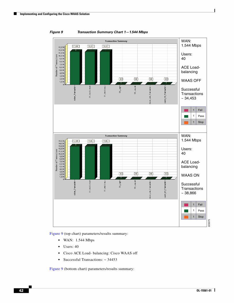
Implementing and Configuring the Cisco WAAS Solution
Figure 9 Transaction Summary Chart 1—1.544 Mbps
Figure 9 (top chart) parameters/results summary:
• WAN: 1.544 Mbps
• Users: 40
• Cisco ACE Load- balancing: Cisco WAAS off
• Successful Transactions: ~ 34453
Figure 9 (bottom chart) parameters/results summary:
WAN: 1.544 Mbps
Users:40
ACE Load-balancing
WAAS OFF
Successful Transactions~ 34,453
Fail1
1 Pass
Stop
WAN: 1.544 Mbps
Users:40
ACE Load-balancing
WAAS ON
Successful Transactions~ 38,866
2230
75
1
Fail1
1 Pass
Stop1
42 OL-15561-01
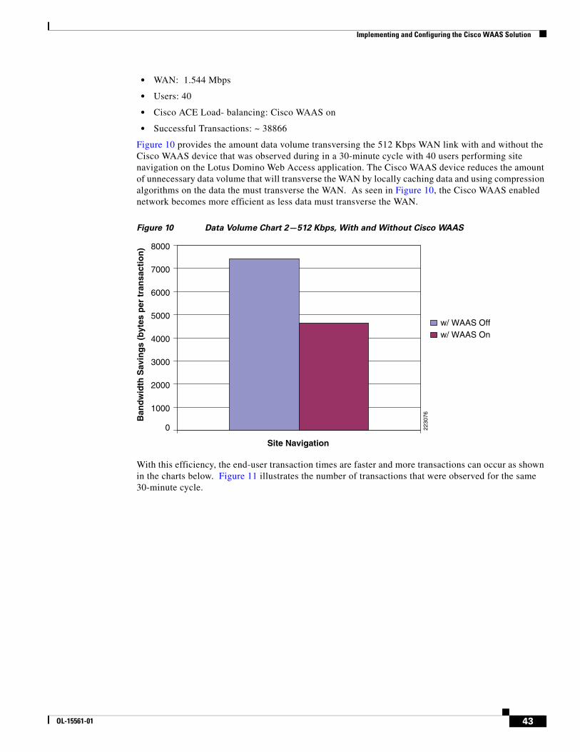
Implementing and Configuring the Cisco WAAS Solution
• WAN: 1.544 Mbps
• Users: 40
• Cisco ACE Load- balancing: Cisco WAAS on
• Successful Transactions: ~ 38866
Figure 10 provides the amount data volume transversing the 512 Kbps WAN link with and without the Cisco WAAS device that was observed during in a 30-minute cycle with 40 users performing site navigation on the Lotus Domino Web Access application. The Cisco WAAS device reduces the amount of unnecessary data volume that will transverse the WAN by locally caching data and using compression algorithms on the data the must transverse the WAN. As seen in Figure 10, the Cisco WAAS enabled network becomes more efficient as less data must transverse the WAN.
Figure 10 Data Volume Chart 2—512 Kbps, With and Without Cisco WAAS
With this efficiency, the end-user transaction times are faster and more transactions can occur as shown in the charts below. Figure 11 illustrates the number of transactions that were observed for the same 30-minute cycle.
2230
760
Site Navigation
w/ WAAS Offw/ WAAS On
7000
8000
6000
5000
4000
3000
2000
1000
Ban
dw
idth
Sav
ing
s (b
ytes
per
tra
nsa
ctio
n)
43OL-15561-01
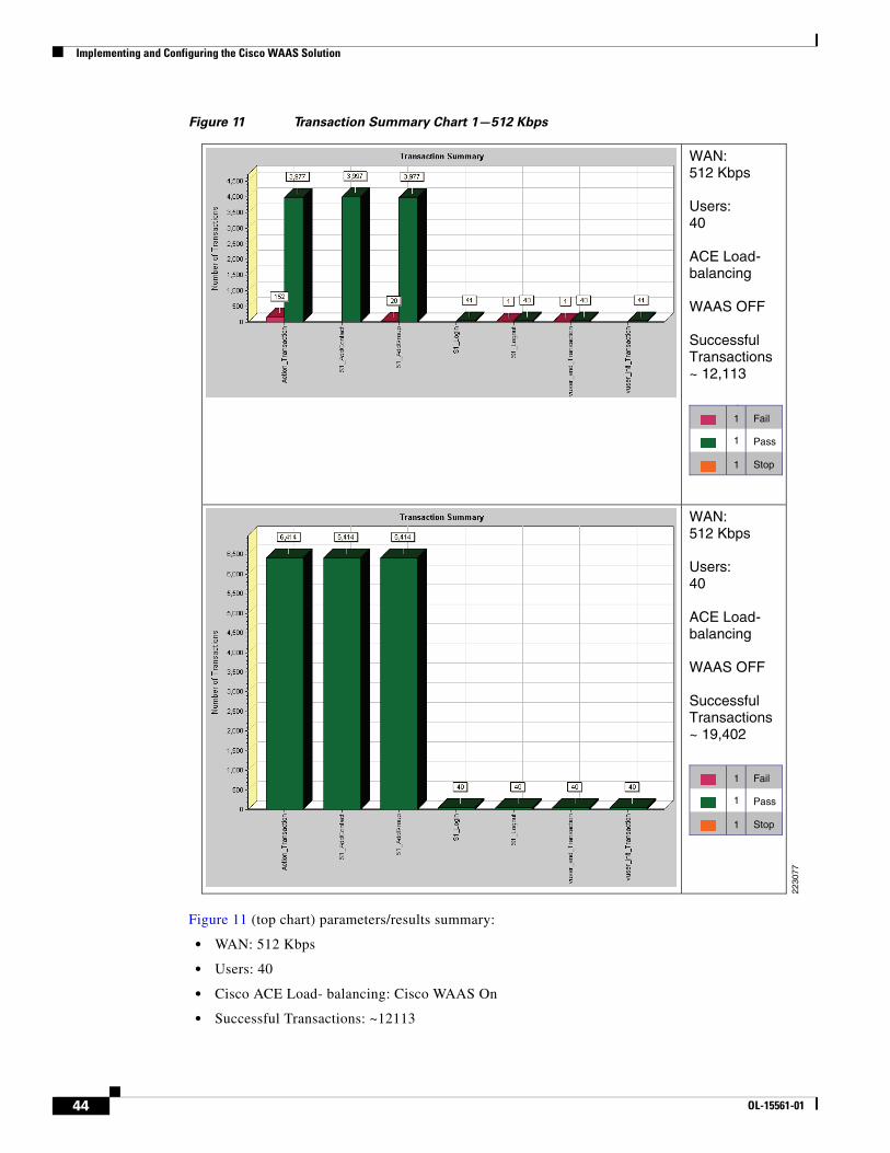
Implementing and Configuring the Cisco WAAS Solution
Figure 11 Transaction Summary Chart 1—512 Kbps
Figure 11 (top chart) parameters/results summary:
• WAN: 512 Kbps
• Users: 40
• Cisco ACE Load- balancing: Cisco WAAS On
• Successful Transactions: ~12113
WAN: 512 Kbps
Users:40
ACE Load-balancing
WAAS OFF
Successful Transactions~ 12,113
Fail1
1 Pass
Stop
WAN: 512 Kbps
Users:40
ACE Load-balancing
WAAS OFF
Successful Transactions~ 19,402
2230
77
1
Fail1
1 Pass
Stop1
44 OL-15561-01
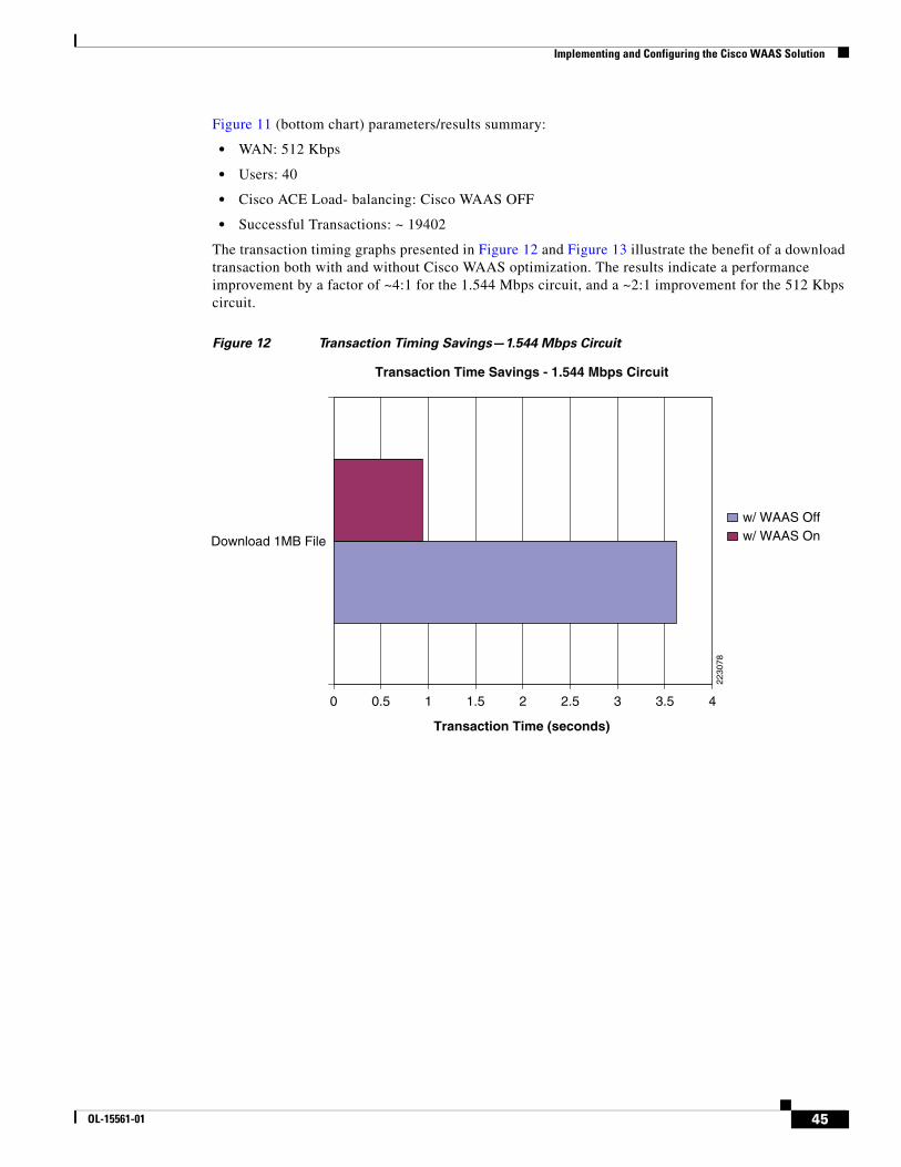
Implementing and Configuring the Cisco WAAS Solution
Figure 11 (bottom chart) parameters/results summary:
• WAN: 512 Kbps
• Users: 40
• Cisco ACE Load- balancing: Cisco WAAS OFF
• Successful Transactions: ~ 19402
The transaction timing graphs presented in Figure 12 and Figure 13 illustrate the benefit of a download transaction both with and without Cisco WAAS optimization. The results indicate a performance improvement by a factor of ~4:1 for the 1.544 Mbps circuit, and a ~2:1 improvement for the 512 Kbps circuit.
Figure 12 Transaction Timing Savings—1.544 Mbps Circuit
2230
78
0
Transaction Time (seconds)
Transaction Time Savings - 1.544 Mbps Circuit
0.5 1 1.5 2 2.5 3 3.5 4
w/ WAAS Off
Download 1MB File w/ WAAS On
45OL-15561-01
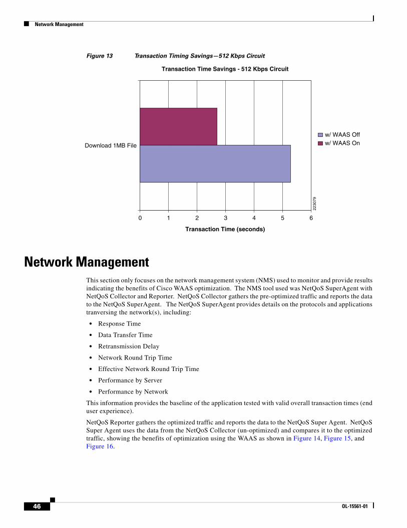
Network Management
Figure 13 Transaction Timing Savings—512 Kbps Circuit
Network Management This section only focuses on the network management system (NMS) used to monitor and provide results indicating the benefits of Cisco WAAS optimization. The NMS tool used was NetQoS SuperAgent with NetQoS Collector and Reporter. NetQoS Collector gathers the pre-optimized traffic and reports the data to the NetQoS SuperAgent. The NetQoS SuperAgent provides details on the protocols and applications tranversing the network(s), including:
• Response Time
• Data Transfer Time
• Retransmission Delay
• Network Round Trip Time
• Effective Network Round Trip Time
• Performance by Server
• Performance by Network
This information provides the baseline of the application tested with valid overall transaction times (end user experience).
NetQoS Reporter gathers the optimized traffic and reports the data to the NetQoS Super Agent. NetQoS Super Agent uses the data from the NetQoS Collector (un-optimized) and compares it to the optimized traffic, showing the benefits of optimization using the WAAS as shown in Figure 14, Figure 15, and Figure 16.
2230
79
0
Transaction Time (seconds)
Transaction Time Savings - 512 Kbps Circuit
1 2 3 4 5 6
w/ WAAS Off
Download 1MB File w/ WAAS On
46 OL-15561-01
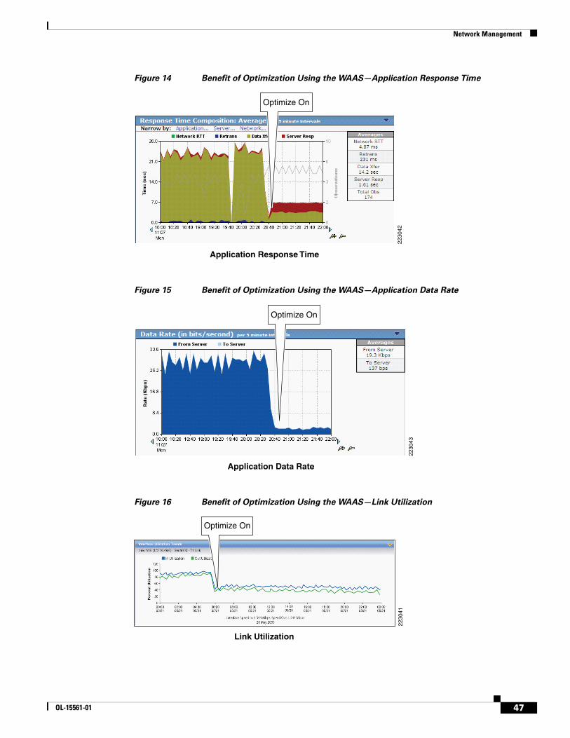
Network Management
Figure 14 Benefit of Optimization Using the WAAS—Application Response Time
Figure 15 Benefit of Optimization Using the WAAS—Application Data Rate
Figure 16 Benefit of Optimization Using the WAAS—Link Utilization
Application Response Time
2230
42
Optimize On
Application Data Rate
2230
43
Optimize On
Link Utilization
Optimize On
2230
41
47OL-15561-01
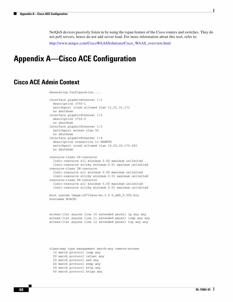
Appendix A—Cisco ACE Configuration
NetQoS devices passively listen in by using the rspan feature of the Cisco routers and switches. They do not poll servers, hence do not add server load. For more information about this tool, refer to:
http://www.netqos.com/CiscoWAASSolutions/Cisco_WAAS_overview.html
Appendix A—Cisco ACE Configuration
Cisco ACE Admin ContextGenerating Configuration....
interface gigabitEthernet 1/1 description 3750-1 switchport trunk allowed vlan 11,21,31,171 no shutdowninterface gigabitEthernet 1/2 description 3750-2 no shutdowninterface gigabitEthernet 1/3 switchport access vlan 50 no shutdowninterface gigabitEthernet 1/4 description connection to WANRTR switchport trunk allowed vlan 10,20,30,170,500 no shutdown
resource-class CX-resource limit-resource all minimum 0.00 maximum unlimited limit-resource sticky minimum 0.01 maximum unlimitedresource-class IN-resource limit-resource all minimum 0.00 maximum unlimited limit-resource sticky minimum 0.01 maximum unlimitedresource-class PS-resource limit-resource all minimum 0.00 maximum unlimited limit-resource sticky minimum 0.01 maximum unlimited
boot system image:c4710ace-mz.3.0.0_AB0_0.500.binhostname DCACE1
access-list anyone line 10 extended permit ip any any access-list anyone line 11 extended permit icmp any any access-list anyone line 12 extended permit tcp any any
class-map type management match-any remote-access 10 match protocol icmp any 20 match protocol telnet any 30 match protocol ssh any 40 match protocol snmp any 50 match protocol http any 60 match protocol https any
48 OL-15561-01

Appendix A—Cisco ACE Configuration
policy-map type management first-match remote-mgt class remote-access permit
interface vlan 10 ip address 10.1.10.7 255.255.255.0 service-policy input remote-mgt no shutdowninterface vlan 20 ip address 10.1.20.100 255.255.255.0 no shutdowninterface vlan 30 ip address 10.1.30.100 255.255.255.0 peer ip address 10.1.30.200 255.255.255.0 service-policy input remote-mgt no shutdowninterface vlan 100 ip address 10.1.100.100 255.255.255.0 no shutdowninterface vlan 500 ip address 10.50.50.2 255.255.255.0 no shutdown
ft interface vlan 50 ip address 1.1.1.1 255.255.255.0 peer ip address 1.1.1.2 255.255.255.0 no shutdown
ft peer 1 heartbeat interval 300 heartbeat count 10 ft-interface vlan 50ft group 2 peer 1 peer priority 99 associate-context Admin inservice
ip route 0.0.0.0 0.0.0.0 10.1.30.1
context citrix description CITRIX Testing allocate-interface vlan 20-21 member CX-resourcecontext inotes description INOTES Testing allocate-interface vlan 10-11 member IN-resourcecontext Lotus iNotes description LOTUS INOTES Testing allocate-interface vlan 30-31 member PS-resource
ft group 3 peer 1 peer priority 99 associate-context inotes inserviceft group 4 peer 1 peer priority 99
49OL-15561-01
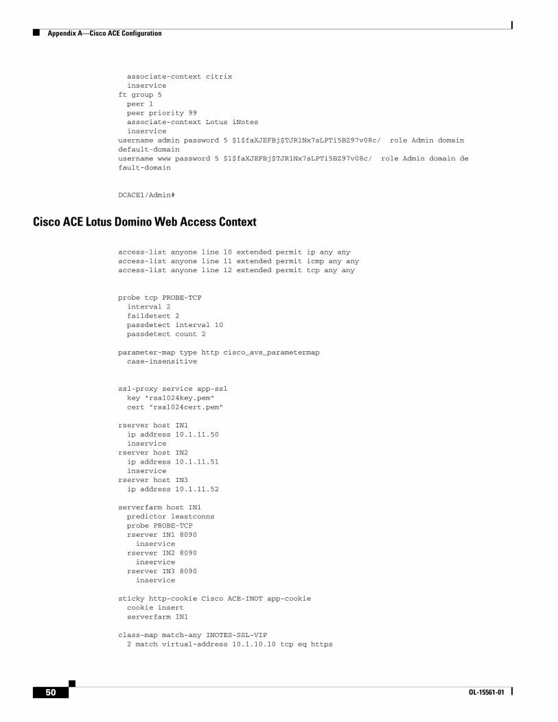
Appendix A—Cisco ACE Configuration
associate-context citrix inserviceft group 5 peer 1 peer priority 99 associate-context Lotus iNotes inserviceusername admin password 5 $1$faXJEFBj$TJR1Nx7sLPTi5BZ97v08c/ role Admin domain default-domain username www password 5 $1$faXJEFBj$TJR1Nx7sLPTi5BZ97v08c/ role Admin domain default-domain
DCACE1/Admin#
Cisco ACE Lotus Domino Web Access Context
access-list anyone line 10 extended permit ip any any access-list anyone line 11 extended permit icmp any any access-list anyone line 12 extended permit tcp any any
probe tcp PROBE-TCP interval 2 faildetect 2 passdetect interval 10 passdetect count 2
parameter-map type http cisco_avs_parametermap case-insensitive
ssl-proxy service app-ssl key "rsa1024key.pem" cert "rsa1024cert.pem"
rserver host IN1 ip address 10.1.11.50 inservicerserver host IN2 ip address 10.1.11.51 inservicerserver host IN3 ip address 10.1.11.52
serverfarm host IN1 predictor leastconns probe PROBE-TCP rserver IN1 8090 inservice rserver IN2 8090 inservice rserver IN3 8090 inservice
sticky http-cookie Cisco ACE-INOT app-cookie cookie insert serverfarm IN1
class-map match-any INOTES-SSL-VIP 2 match virtual-address 10.1.10.10 tcp eq https
50 OL-15561-01

Appendix A—Cisco ACE Configuration
class-map match-any INOTES-VIP 2 match virtual-address 10.1.10.10 tcp eq www class-map type management match-any remote-access 10 match protocol icmp any 20 match protocol telnet any 30 match protocol ssh any 40 match protocol snmp any 50 match protocol http any 60 match protocol https any
policy-map type management first-match remote-mgt class remote-access permitpolicy-map type loadbalance first-match INOTES-VIP-l7slb class class-default sticky-serverfarm app-cookiepolicy-map multi-match LB-VIP class INOTES-VIP loadbalance vip inservice loadbalance policy INOTES-VIP-l7slb loadbalance vip icmp-reply appl-parameter http advanced-options cisco_avs_parametermap class INOTES-SSL-VIP loadbalance vip inservice loadbalance policy INOTES-VIP-l7slb loadbalance vip icmp-reply appl-parameter http advanced-options cisco_avs_parametermap ssl-proxy server "app-ssl"
interface vlan 10 ip address 10.1.10.5 255.255.255.0 alias 10.1.10.2 255.255.255.0 peer ip address 10.1.10.6 255.255.255.0 access-group input anyone access-group output anyone service-policy input remote-mgt service-policy input LB-VIP no shutdowninterface vlan 11 ip address 10.1.11.2 255.255.255.0 alias 10.1.11.1 255.255.255.0 peer ip address 10.1.11.3 255.255.255.0 access-group input anyone access-group output anyone service-policy input remote-mgt no shutdown
role RSERVER-MOD rule 1 permit modify feature rserver
ip route 0.0.0.0 0.0.0.0 10.1.10.1username cisco_inotes password 5 $1$aXv9VJ4w$SRNJixvS5Cj4UULIDCV4v. role Admin domain default-domain username admin password 5 admin role Network-Monitor domain default-domain username cisco_test password 5 $1$m8e2GwOU$ty2Q6v5RAQ0z/2DnXKiFe. role Network-Monitor domain default-domain username inotes password 5 $1$0h05Peb.$6NADoU3ot8QRjaSnqYBMy/ role RSERVER-MOD domain default-domain
51OL-15561-01
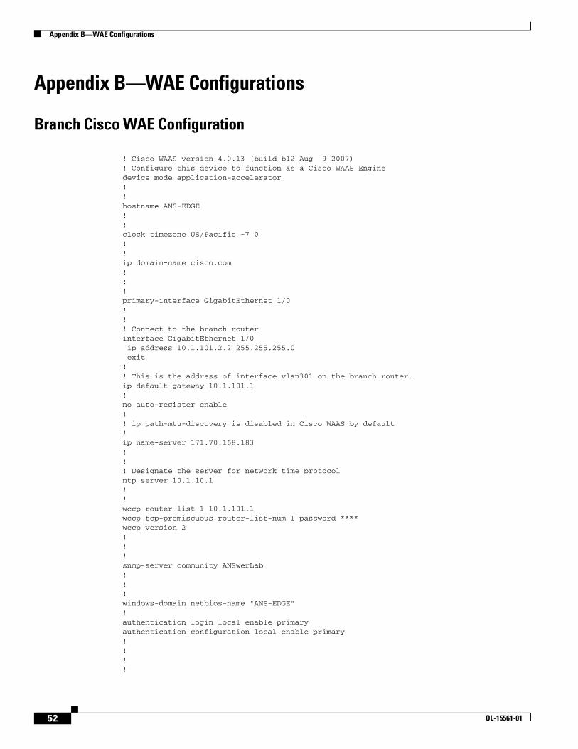
Appendix B—WAE Configurations
Appendix B—WAE Configurations
Branch Cisco WAE Configuration
! Cisco WAAS version 4.0.13 (build b12 Aug 9 2007)! Configure this device to function as a Cisco WAAS Enginedevice mode application-accelerator!!hostname ANS-EDGE!!clock timezone US/Pacific -7 0!!ip domain-name cisco.com!!!primary-interface GigabitEthernet 1/0!!! Connect to the branch routerinterface GigabitEthernet 1/0 ip address 10.1.101.2.2 255.255.255.0 exit!! This is the address of interface vlan301 on the branch router.ip default-gateway 10.1.101.1!no auto-register enable!! ip path-mtu-discovery is disabled in Cisco WAAS by default!ip name-server 171.70.168.183!!! Designate the server for network time protocolntp server 10.1.10.1!!wccp router-list 1 10.1.101.1wccp tcp-promiscuous router-list-num 1 password ****wccp version 2!!!snmp-server community ANSwerLab!!!windows-domain netbios-name "ANS-EDGE"!authentication login local enable primaryauthentication configuration local enable primary!!!!
52 OL-15561-01
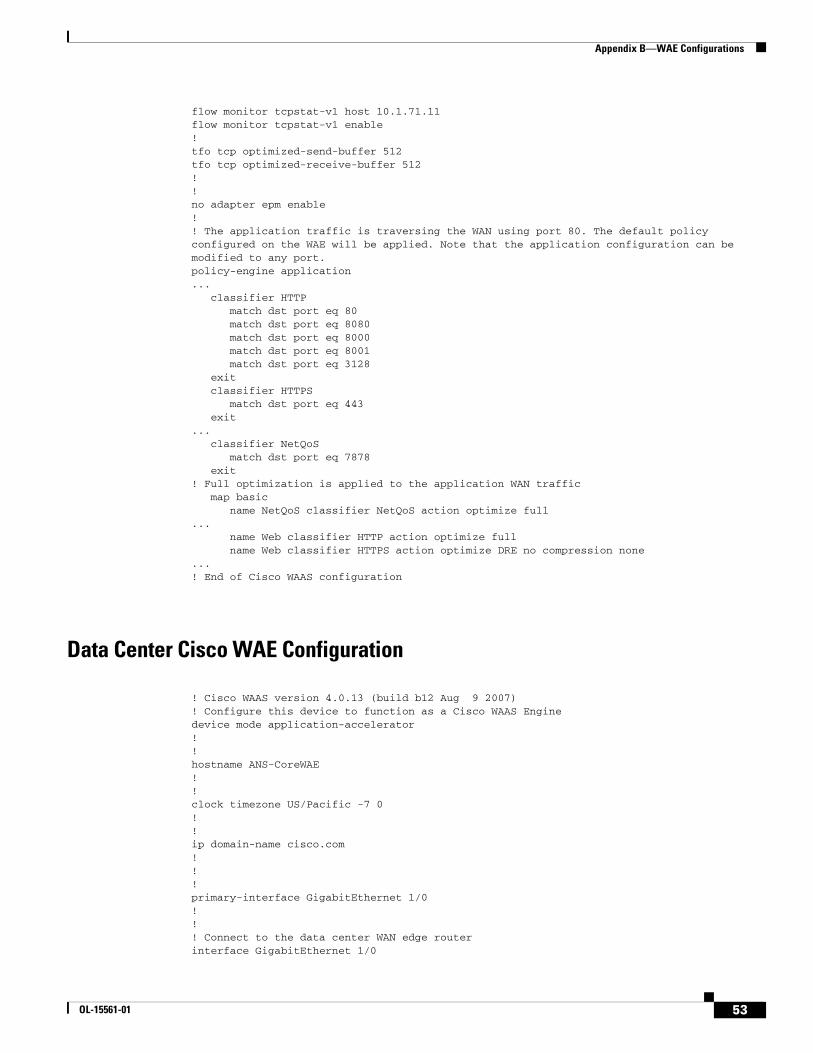
Appendix B—WAE Configurations
flow monitor tcpstat-v1 host 10.1.71.11flow monitor tcpstat-v1 enable!tfo tcp optimized-send-buffer 512tfo tcp optimized-receive-buffer 512!!no adapter epm enable!! The application traffic is traversing the WAN using port 80. The default policy configured on the WAE will be applied. Note that the application configuration can be modified to any port.policy-engine application... classifier HTTP match dst port eq 80 match dst port eq 8080 match dst port eq 8000 match dst port eq 8001 match dst port eq 3128 exit classifier HTTPS match dst port eq 443 exit... classifier NetQoS match dst port eq 7878 exit! Full optimization is applied to the application WAN traffic map basic name NetQoS classifier NetQoS action optimize full... name Web classifier HTTP action optimize full name Web classifier HTTPS action optimize DRE no compression none...! End of Cisco WAAS configuration
Data Center Cisco WAE Configuration
! Cisco WAAS version 4.0.13 (build b12 Aug 9 2007)! Configure this device to function as a Cisco WAAS Enginedevice mode application-accelerator!!hostname ANS-CoreWAE!!clock timezone US/Pacific -7 0!!ip domain-name cisco.com!!!primary-interface GigabitEthernet 1/0!!! Connect to the data center WAN edge routerinterface GigabitEthernet 1/0
53OL-15561-01

Appendix B—WAE Configurations
ip address 10.1.100.100.2 255.255.255.0 exit!!! This is the address of interface GigabitEthernet2/0 on data center WAN edge router.ip default-gateway 10.1.100.100.1!no auto-register enable!! ip path-mtu-discovery is disabled in Cisco WAAS by default!!!! Designate the server for network time protocolntp server 10.1.10.1!!wccp router-list 1 10.1.100.100.1wccp tcp-promiscuous router-list-num 1 password ****wccp version 2!!!snmp-server community ANSwerLab!!!windows-domain netbios-name "ANS-COREWAE"!authentication login local enable primaryauthentication configuration local enable primary!!!!!flow monitor tcpstat-v1 host 10.1.71.11flow monitor tcpstat-v1 enable!tfo tcp optimized-send-buffer 2048tfo tcp optimized-receive-buffer 2048!!! The application traffic is traversing the WAN using port 80. The default policy configured on the WAE will be applied. Note that the application configuration can be modified to any port.policy-engine application... classifier HTTP match dst port eq 80 match dst port eq 8080 match dst port eq 8000 match dst port eq 8001 match dst port eq 3128 exit classifier HTTPS match dst port eq 443 exit... classifier NetQoS match dst port eq 7878 exit! Full optimization is applied to the application WAN traffic map basic
54 OL-15561-01
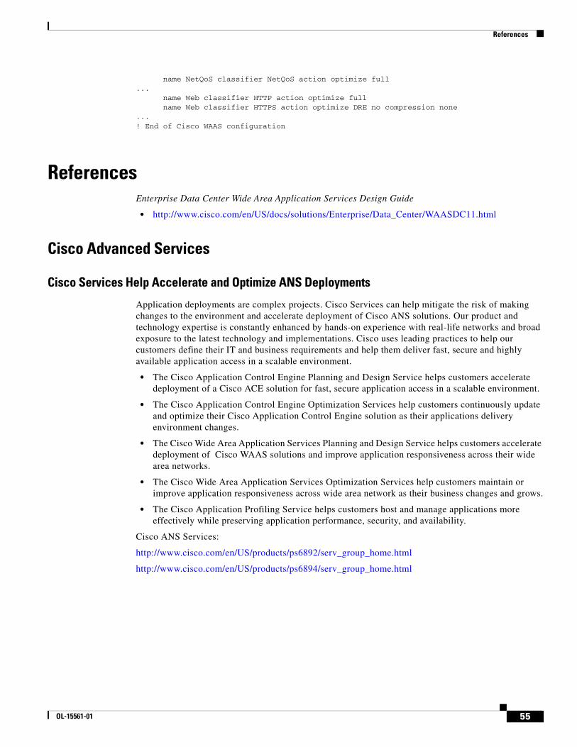
References
name NetQoS classifier NetQoS action optimize full... name Web classifier HTTP action optimize full name Web classifier HTTPS action optimize DRE no compression none...! End of Cisco WAAS configuration
ReferencesEnterprise Data Center Wide Area Application Services Design Guide
• http://www.cisco.com/en/US/docs/solutions/Enterprise/Data_Center/WAASDC11.html
Cisco Advanced Services
Cisco Services Help Accelerate and Optimize ANS Deployments
Application deployments are complex projects. Cisco Services can help mitigate the risk of making changes to the environment and accelerate deployment of Cisco ANS solutions. Our product and technology expertise is constantly enhanced by hands-on experience with real-life networks and broad exposure to the latest technology and implementations. Cisco uses leading practices to help our customers define their IT and business requirements and help them deliver fast, secure and highly available application access in a scalable environment.
• The Cisco Application Control Engine Planning and Design Service helps customers accelerate deployment of a Cisco ACE solution for fast, secure application access in a scalable environment.
• The Cisco Application Control Engine Optimization Services help customers continuously update and optimize their Cisco Application Control Engine solution as their applications delivery environment changes.
• The Cisco Wide Area Application Services Planning and Design Service helps customers accelerate deployment of Cisco WAAS solutions and improve application responsiveness across their wide area networks.
• The Cisco Wide Area Application Services Optimization Services help customers maintain or improve application responsiveness across wide area network as their business changes and grows.
• The Cisco Application Profiling Service helps customers host and manage applications more effectively while preserving application performance, security, and availability.
Cisco ANS Services:
http://www.cisco.com/en/US/products/ps6892/serv_group_home.html
http://www.cisco.com/en/US/products/ps6894/serv_group_home.html
55OL-15561-01
Cisco Validated Design
Cisco Validated Design The Cisco Validated Design Program consists of systems and solutions designed, tested, and documented to facilitate faster, more reliable, and more predictable customer deployments. For more information visit www.cisco.com/go/validateddesigns.
ALL DESIGNS, SPECIFICATIONS, STATEMENTS, INFORMATION, AND RECOMMENDATIONS (COLLECTIVELY, "DESIGNS") IN THIS MANUAL ARE PRESENTED "AS IS," WITH ALL FAULTS. CISCO AND ITS SUPPLIERS DISCLAIM ALL WARRANTIES, INCLUDING, WITHOUT LIMITATION, THE WARRANTY OF MERCHANTABILITY, FITNESS FOR A PARTICULAR PURPOSE AND NONINFRINGEMENT OR ARISING FROM A COURSE OF DEALING, USAGE, OR TRADE PRACTICE. IN NO EVENT SHALL CISCO OR ITS SUPPLIERS BE LIABLE FOR ANY INDIRECT, SPECIAL, CONSEQUENTIAL, OR INCIDENTAL DAMAGES, INCLUDING, WITHOUT LIMITATION, LOST PROFITS OR LOSS OR DAMAGE TO DATA ARISING OUT OF THE USE OR INABILITY TO USE THE DESIGNS, EVEN IF CISCO OR ITS SUPPLIERS HAVE BEEN ADVISED OF THE POSSIBILITY OF SUCH DAMAGES.
THE DESIGNS ARE SUBJECT TO CHANGE WITHOUT NOTICE. USERS ARE SOLELY RESPONSIBLE FOR THEIR APPLICATION OF THE DESIGNS. THE DESIGNS DO NOT CONSTITUTE THE TECHNICAL OR OTHER PROFESSIONAL ADVICE OF CISCO, ITS SUPPLIERS OR PARTNERS. USERS SHOULD CONSULT THEIR OWN TECHNICAL ADVISORS BEFORE IMPLEMENTING THE DESIGNS. RESULTS MAY VARY DEPENDING ON FACTORS NOT TESTED BY CISCO.
CCDE, CCENT, Cisco Eos, Cisco Lumin, Cisco Nexus, Cisco StadiumVision, Cisco TelePresence, the Cisco logo, DCE, and Welcome to the Human Network are trademarks; Changing the Way We Work, Live, Play, and Learn and Cisco Store are service marks; and Access Registrar, Aironet, AsyncOS, Bringing the Meeting To You, Catalyst, CCDA, CCDP, CCIE, CCIP, CCNA, CCNP, CCSP, CCVP, Cisco, the Cisco Certified Internetwork Expert logo, Cisco IOS, Cisco Press, Cisco Systems, Cisco Systems Capital, the Cisco Systems logo, Cisco Unity, Collaboration Without Limitation, EtherFast, EtherSwitch, Event Center, Fast Step, Follow Me Browsing, FormShare, GigaDrive, HomeLink, Internet Quotient, IOS, iPhone, iQ Expertise, the iQ logo, iQ Net Readiness Scorecard, iQuick Study, IronPort, the IronPort logo, LightStream, Linksys, MediaTone, MeetingPlace, MeetingPlace Chime Sound, MGX, Networkers, Networking Academy, Network Registrar, PCNow, PIX, PowerPanels, ProConnect, ScriptShare, SenderBase, SMARTnet, Spectrum Expert, StackWise, The Fastest Way to Increase Your Internet Quotient, TransPath, WebEx, and the WebEx logo are registered trademarks of Cisco Systems, Inc. and/or its affiliates in the United States and certain other countries.
All other trademarks mentioned in this document or Website are the property of their respective owners. The use of the word partner does not imply a partnership relationship between Cisco and any other company. (0807R)
56 OL-15561-01