Embed Size (px)
Citation preview
Cisco Catalyst 9300 Series Switches By Cisco Systems, Inc.
FIPS 140-2 Non-Proprietary Security Policy Level 1 Validation
Version 1.1
May 8th, 2020
Table of Contents
1 INTRODUCTION .................................................................................................................. 3
1.1 PURPOSE ............................................................................................................................. 3 1.2 MODULES VALIDATION LEVEL ........................................................................................... 3 1.3 REFERENCES ....................................................................................................................... 4 1.4 TERMINOLOGY ................................................................................................................... 4
1.5 DOCUMENT ORGANIZATION ............................................................................................... 4
2 CISCO SYSTEMS CATALYST 9300 SERIES SWITCHES ............................................ 5
2.1 CRYPTOGRAPHIC MODULES INTERFACES AND PHYSICAL CHARACTERISTICS ..................... 6 2.2 ROLES, SERVICES AND AUTHENTICATION .......................................................................... 8
2.2.1 User Role ...................................................................................................... 8
2.2.2 Crypto-Officer Role ........................................................................................ 9 2.2.3 Unauthorized Role ....................................................................................... 11
2.2.4 Services Available in Non-FIPS Mode of Operation .................................... 11 2.3 CRYPTOGRAPHIC ALGORITHMS ........................................................................................ 13 2.4 CRYPTOGRAPHIC KEY/CSP MANAGEMENT ...................................................................... 15 2.5 SELF-TESTS ...................................................................................................................... 19
2.5.1 Power-On Self-Tests (POSTs) .................................................................... 19 2.5.2 Conditional Tests ......................................................................................... 20
2.6 PHYSICAL SECURITY......................................................................................................... 21
3 SECURE OPERATION ...................................................................................................... 21
3.1 SYSTEM INITIALIZATION AND CONFIGURATION ................................................................ 21
1 Introduction
1.1 Purpose This document is the non-proprietary Cryptographic Module Security Policy for the Cisco Catalyst 9300 Series Switches running
IOS-XE Firmware Versions 16.9.2 or 16.12. This security policy describes how the modules listed below meet the security
requirements of FIPS 140-2 level 1, and how to operate the switches with on-board crypto enabled in a secure FIPS 140-2 mode.
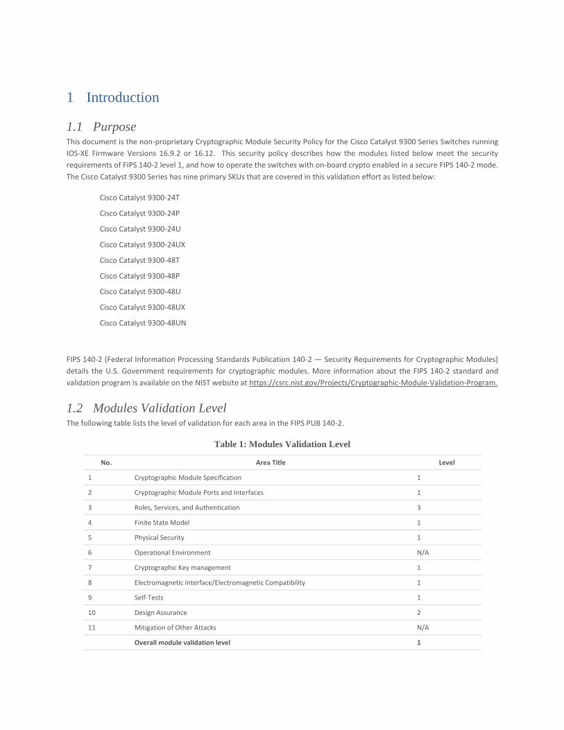
The Cisco Catalyst 9300 Series has nine primary SKUs that are covered in this validation effort as listed below:
Cisco Catalyst 9300-24T
Cisco Catalyst 9300-24P
Cisco Catalyst 9300-24U
Cisco Catalyst 9300-24UX
Cisco Catalyst 9300-48T
Cisco Catalyst 9300-48P
Cisco Catalyst 9300-48U
Cisco Catalyst 9300-48UX
Cisco Catalyst 9300-48UN
FIPS 140-2 (Federal Information Processing Standards Publication 140-2 — Security Requirements for Cryptographic Modules)
details the U.S. Government requirements for cryptographic modules. More information about the FIPS 140-2 standard and
validation program is available on the NIST website at https://csrc.nist.gov/Projects/Cryptographic-Module-Validation-Program.
1.2 Modules Validation Level The following table lists the level of validation for each area in the FIPS PUB 140-2.
Table 1: Modules Validation Level
No. Area Title Level
1 Cryptographic Module Specification 1
2 Cryptographic Module Ports and Interfaces 1
3 Roles, Services, and Authentication 3
4 Finite State Model 1
5 Physical Security 1
6 Operational Environment N/A
7 Cryptographic Key management 1
8 Electromagnetic Interface/Electromagnetic Compatibility 1
9 Self-Tests 1
10 Design Assurance 2
11 Mitigation of Other Attacks N/A
Overall module validation level 1
1.3 References This document deals only with operations and capabilities of the modules in the technical terms of a FIPS 140-2 cryptographic
module security policy. More information is available on the switches from the following sources:
The Cisco Systems website contains information on the full line of Cisco products. Please refer to the following websites for:
Cisco Catalyst 9300 Series Switches -
https://www.cisco.com/c/en/us/products/switches/catalyst-9300-series-switches/index.html
For answers to technical or sales related questions, please refer to the contacts listed on the Cisco Systems website at
www.cisco.com.
The NIST Validated Modules website (http://csrc.nist.gov/groups/STM/cmvp/validation.html) contains contact information for
answers to technical or sales-related questions for the modules.
1.4 Terminology In this document, the Cisco Catalyst 9300 Series Switches is referred to as C9300 switches, the switches, the devices, the
cryptographic modules, or the modules.
1.5 Document Organization The Security Policy document is part of the FIPS 140-2 Submission Package. In addition to this document, the Submission Package
contains:
Vendor Evidence document Finite State Machine Other supporting documentation as additional references
This document provides an overview of the Cisco Catalyst 9300 Series Switches and explains the secure configuration and
operation of the modules. This introduction section is followed by Section 2, which details the general features and functionality
of the switches. Section 3 specifically addresses the required configuration for the FIPS-mode of operation.
With the exception of this Non-Proprietary Security Policy, the FIPS 140-2 Validation Submission Documentation is Cisco-
proprietary and is releasable only under appropriate non-disclosure agreements. For access to these documents, please contact
Cisco Systems.
2 Cisco Systems Catalyst 9300 Series Switches Cisco Catalyst 9300 Series Switches are the next generation of enterprise-class stackable access-layer switches that are part of
the Cisco Catalyst 9000 family. These switches also support full IEEE802.3at PoE+, Cisco UPOE, modular and field-replaceable
network modules, redundant fans, and power supplies. In addition, the Cisco Catalyst 9300-based models support a variety of
uplink modules for both copper and fiber uplink support. These models add even more flexibility to the interface choices that
you can make in a single Cisco Catalyst 9300 Series Switches or in a stack of Cisco Catalyst 9300 Series Switches.
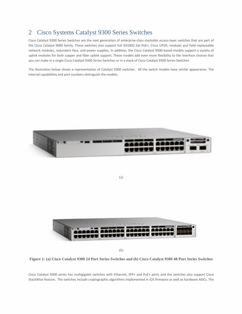
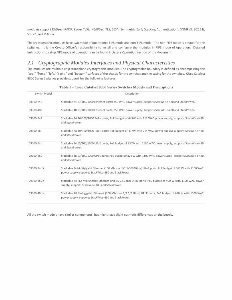
The illustration below shows a representation of Catalyst 9300 switches. All the switch models have similar appearance. The
internal capabilities and port numbers distinguish the models.
(a)
(b)
Figure 1: (a) Cisco Catalyst 9300 24 Port Series Switches and (b) Cisco Catalyst 9300 48 Port Series Switches
Cisco Catalyst 9300 series has multigigabit switches with Ethernet, SFP+ and PoE+ ports and the switches also support Cisco
StackWise feature. The switches include cryptographic algorithms implemented in IOS firmware as well as hardware ASICs. The
modules support RADsec (RADIUS over TLS), IKE/IPSec, TLS, SESA (Symmetric Early Stacking Authentication), SNMPv3, 802.11i,
SSHv2, and MACsec.
The cryptographic modules have two mode of operations: FIPS mode and non-FIPS mode. The non-FIPS mode is default for the
switches. It is the Crypto-Officer’s responsibility to install and configure the modules in FIPS mode of operation. Detailed
instructions to setup FIPS mode of operation can be found in Secure Operation section of this document.
2.1 Cryptographic Modules Interfaces and Physical Characteristics The modules are multiple-chip standalone cryptographic modules. The cryptographic boundary is defined as encompassing the
“top,” “front,” “left,” “right,” and “bottom” surfaces of the chassis for the switches and the casing for the switches. Cisco Catalyst
9300 Series Switches provide support for the following features:
Table 2 - Cisco Catalyst 9300 Series Switches Models and Descriptions
Switch Model Description
C9300-24T Stackable 24 10/100/1000 Ethernet ports; 350 WAC power supply; supports StackWise-480 and StackPower.
C9300-48T Stackable 48 10/100/1000 Ethernet ports; 350 WAC power supply; supports StackWise-480 and StackPower.
C9300-24P Stackable 24 10/100/1000 PoE+ ports; PoE budget of 445W with 715 WAC power supply; supports StackWise-480
and StackPower.
C9300-48P Stackable 48 10/100/1000 PoE+ ports; PoE budget of 437W with 715 WAC power supply; supports StackWise-480
and StackPower.
C9300-24U Stackable 24 10/100/1000 UPoE ports; PoE budget of 830W with 1100 WAC power supply; supports StackWise-480
and StackPower.
C9300-48U Stackable 48 10/100/1000 UPoE ports; PoE budget of 822 W with 1100 WAC power supply; supports StackWise-480
and StackPower.
C9300-24UX Stackable 24 Multigigabit Ethernet (100 Mbps or 1/2.5/5/10Gbps) UPoE ports; PoE budget of 560 W with 1100 WAC
power supply; supports StackWise-480 and StackPower.
C9300-48UX Stackable 48 (12 Multigigabit Ethernet and 36 2.5Gbps) UPoE ports; PoE budget of 490 W with 1100 WAC power
supply; supports StackWise-480 and StackPower.
C9300-48UN Stackable 48 Multigigabit Ethernet (100 Mbps or 1/2.5/5 Gbps) UPoE ports; PoE budget of 610 W with 1100 WAC
power supply; supports StackWise-480 and StackPower.
All the switch models have similar components, but might have slight cosmetic differences on the bezels.
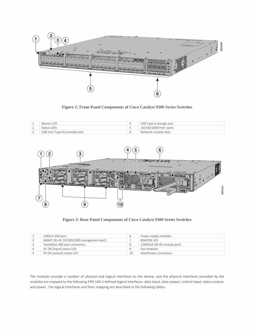
Figure 2: Front Panel Components of Cisco Catalyst 9300 Series Switches
1 Beacon LED 4 USB Type A storage port
2 Status LEDs 5 10/100/1000 PoE+ ports
3 USB mini-Type B (console) port 6 Network module slots
Figure 3: Rear Panel Components of Cisco Catalyst 9300 Series Swtiches
1 USB3.0–SSD port 6 Power supply modules
2 MGMT (RJ-45 10/100/1000 management port) 7 BEACON LED
3 StackWise-480 port connectors 8 CONSOLE (RJ-45 console port)
4 AC OK (input) status LED 9 Fan modules
5 PS OK (output) status LED 10 StackPower connectors
The modules provide a number of physical and logical interfaces to the device, and the physical interfaces provided by the
modules are mapped to the following FIPS 140-2 defined logical interfaces: data input, data output, control input, status output,
and power. The logical interfaces and their mapping are described in the following tables.
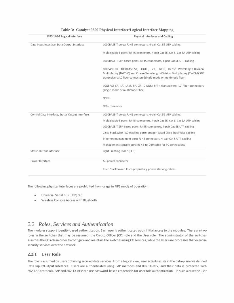
Table 3: Catalyst 9300 Physical Interface/Logical Interface Mapping
FIPS 140-2 Logical Interface Physical Interfaces and Cabling
Data Input Interface, Data Output Interface 1000BASE-T ports: RJ-45 connectors, 4-pair Cat 5E UTP cabling
Multigigabit-T ports: RJ-45 connectors, 4-pair Cat 5E, Cat 6, Cat 6A UTP cabling
1000BASE-T SFP-based ports: RJ-45 connectors, 4-pair Cat 5E UTP cabling
100BASE-FX, 1000BASE-SX, -LX/LH, -ZX, -BX10, Dense Wavelength-Division
Multiplexing (DWDM) and Coarse Wavelength-Division Multiplexing (CWDM) SFP
transceivers: LC fiber connectors (single-mode or multimode fiber)
10GBASE-SR, LR, LRM, ER, ZR, DWDM SFP+ transceivers: LC fiber connectors
(single-mode or multimode fiber)
QSFP
SFP+ connector
Control Data Interface, Status Output Interface 1000BASE-T ports: RJ-45 connectors, 4-pair Cat 5E UTP cabling
Multigigabit-T ports: RJ-45 connectors, 4-pair Cat 5E, Cat 6, Cat 6A UTP cabling
1000BASE-T SFP-based ports: RJ-45 connectors, 4-pair Cat 5E UTP cabling
Cisco StackWise-480 stacking ports: copper-based Cisco StackWise cabling
Ethernet management port: RJ-45 connectors, 4-pair Cat 5 UTP cabling
Management console port: RJ-45-to-DB9 cable for PC connections
Status Output Interface Light Emitting Diode (LED)
Power Interface AC power connector
Cisco StackPower: Cisco proprietary power stacking cables
The following physical interfaces are prohibited from usage in FIPS mode of operation:
• Universal Serial Bus (USB) 3.0
• Wireless Console Access with Bluetooth
2.2 Roles, Services and Authentication The modules support identity-based authentication. Each user is authenticated upon initial access to the modules. There are two
roles in the switches that may be assumed: the Crypto-Officer (CO) role and the User role. The administrator of the switches
assumes the CO role in order to configure and maintain the switches using CO services, while the Users are processes that exercise
security services over the network.
2.2.1 User Role
The role is assumed by users obtaining secured data services. From a logical view, user activity exists in the data-plane via defined
Data Input/Output Intefaces. Users are authenticated using EAP methods and 802.1X-REV, and their data is protected with
802.1AE protocols. EAP and 802.1X-REV can use password-based credentials for User role authentication – in such a case the user
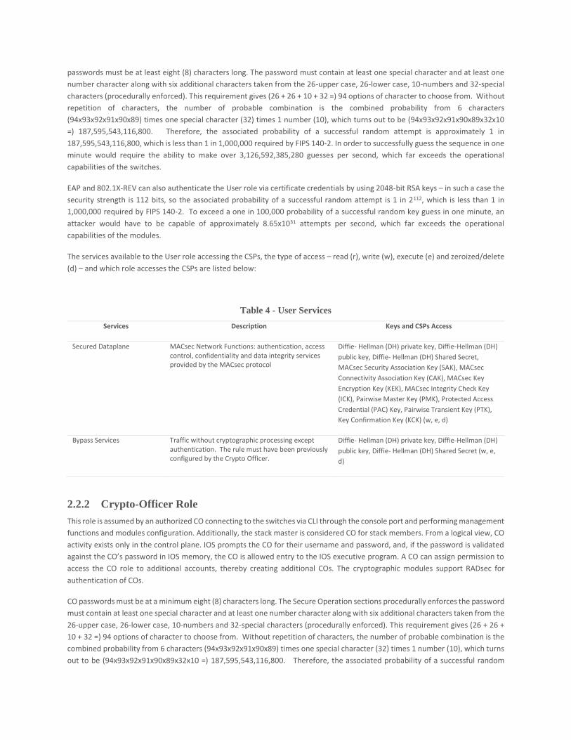
passwords must be at least eight (8) characters long. The password must contain at least one special character and at least one
number character along with six additional characters taken from the 26-upper case, 26-lower case, 10-numbers and 32-special
characters (procedurally enforced). This requirement gives (26 + 26 + 10 + 32 =) 94 options of character to choose from. Without
repetition of characters, the number of probable combination is the combined probability from 6 characters
(94x93x92x91x90x89) times one special character (32) times 1 number (10), which turns out to be (94x93x92x91x90x89x32x10
=) 187,595,543,116,800. Therefore, the associated probability of a successful random attempt is approximately 1 in
187,595,543,116,800, which is less than 1 in 1,000,000 required by FIPS 140-2. In order to successfully guess the sequence in one
minute would require the ability to make over 3,126,592,385,280 guesses per second, which far exceeds the operational
capabilities of the switches.
EAP and 802.1X-REV can also authenticate the User role via certificate credentials by using 2048-bit RSA keys – in such a case the
security strength is 112 bits, so the associated probability of a successful random attempt is 1 in 2112, which is less than 1 in
1,000,000 required by FIPS 140-2. To exceed a one in 100,000 probability of a successful random key guess in one minute, an
attacker would have to be capable of approximately 8.65x1031 attempts per second, which far exceeds the operational
capabilities of the modules.
The services available to the User role accessing the CSPs, the type of access – read (r), write (w), execute (e) and zeroized/delete
(d) – and which role accesses the CSPs are listed below:
Table 4 - User Services
Services Description Keys and CSPs Access
Secured Dataplane
MACsec Network Functions: authentication, access control, confidentiality and data integrity services provided by the MACsec protocol
Diffie- Hellman (DH) private key, Diffie-Hellman (DH)
public key, Diffie- Hellman (DH) Shared Secret,
MACsec Security Association Key (SAK), MACsec
Connectivity Association Key (CAK), MACsec Key
Encryption Key (KEK), MACsec Integrity Check Key
(ICK), Pairwise Master Key (PMK), Protected Access
Credential (PAC) Key, Pairwise Transient Key (PTK),
Key Confirmation Key (KCK) (w, e, d)
Bypass Services Traffic without cryptographic processing except authentication. The rule must have been previously configured by the Crypto Officer.
Diffie- Hellman (DH) private key, Diffie-Hellman (DH)
public key, Diffie- Hellman (DH) Shared Secret (w, e,
d)
2.2.2 Crypto-Officer Role
This role is assumed by an authorized CO connecting to the switches via CLI through the console port and performing management
functions and modules configuration. Additionally, the stack master is considered CO for stack members. From a logical view, CO
activity exists only in the control plane. IOS prompts the CO for their username and password, and, if the password is validated
against the CO’s password in IOS memory, the CO is allowed entry to the IOS executive program. A CO can assign permission to
access the CO role to additional accounts, thereby creating additional COs. The cryptographic modules support RADsec for
authentication of COs.
CO passwords must be at a minimum eight (8) characters long. The Secure Operation sections procedurally enforces the password
must contain at least one special character and at least one number character along with six additional characters taken from the
26-upper case, 26-lower case, 10-numbers and 32-special characters (procedurally enforced). This requirement gives (26 + 26 +
10 + 32 =) 94 options of character to choose from. Without repetition of characters, the number of probable combination is the
combined probability from 6 characters (94x93x92x91x90x89) times one special character (32) times 1 number (10), which turns
out to be (94x93x92x91x90x89x32x10 =) 187,595,543,116,800. Therefore, the associated probability of a successful random
attempt is approximately 1 in 187,595,543,116,800, which is less than 1 in 1,000,000 required by FIPS 140-2. In order to
successfully guess the sequence in one minute would require the ability to make over 3,126,592,385,280 guesses per second,
which far exceeds the operational capabilities of the modules.
Additionally, on a stack, the CO is authenticated via possession of a SESA Authorization key that is 128 bits long. So, an attacker
would have a 1 in 2128 chance of a successful authentication which is much stronger than the one in a million-chance required by
FIPS 140-2. To exceed a one in 100,000 probability of a successful random key guess in one minute, an attacker would have to be
capable of approximately 5.67x1036 attempts per second, which is less than 1 in 100,000 and far exceeds the operational
capabilities of the modules.
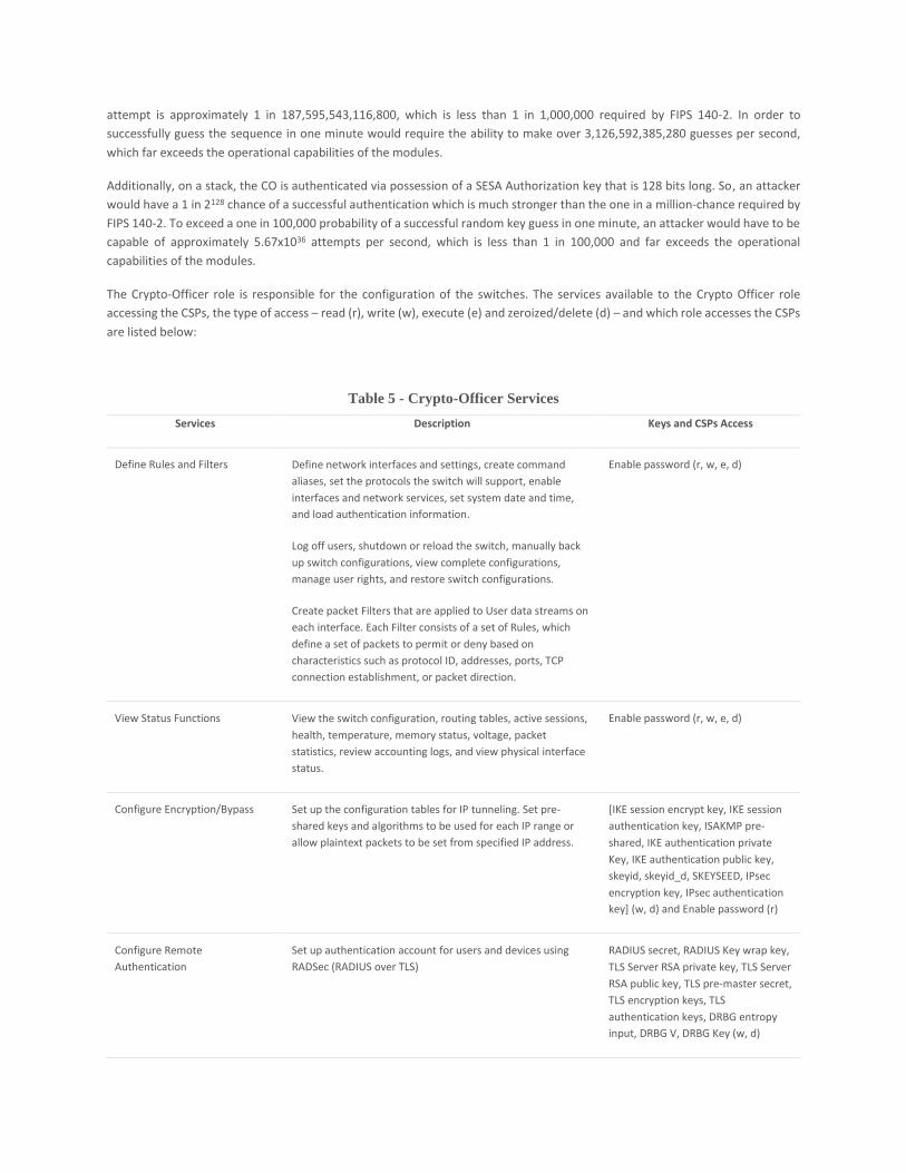
The Crypto-Officer role is responsible for the configuration of the switches. The services available to the Crypto Officer role
accessing the CSPs, the type of access – read (r), write (w), execute (e) and zeroized/delete (d) – and which role accesses the CSPs
are listed below:
Table 5 - Crypto-Officer Services
Services Description Keys and CSPs Access
Define Rules and Filters Define network interfaces and settings, create command
aliases, set the protocols the switch will support, enable
interfaces and network services, set system date and time,
and load authentication information.
Log off users, shutdown or reload the switch, manually back
up switch configurations, view complete configurations,
manage user rights, and restore switch configurations.
Create packet Filters that are applied to User data streams on
each interface. Each Filter consists of a set of Rules, which
define a set of packets to permit or deny based on
characteristics such as protocol ID, addresses, ports, TCP
connection establishment, or packet direction.
Enable password (r, w, e, d)
View Status Functions View the switch configuration, routing tables, active sessions,
health, temperature, memory status, voltage, packet
statistics, review accounting logs, and view physical interface
status.
Enable password (r, w, e, d)
Configure Encryption/Bypass Set up the configuration tables for IP tunneling. Set pre-
shared keys and algorithms to be used for each IP range or
allow plaintext packets to be set from specified IP address.
[IKE session encrypt key, IKE session
authentication key, ISAKMP pre-
shared, IKE authentication private
Key, IKE authentication public key,
skeyid, skeyid_d, SKEYSEED, IPsec
encryption key, IPsec authentication
key] (w, d) and Enable password (r)
Configure Remote
Authentication
Set up authentication account for users and devices using
RADSec (RADIUS over TLS)
RADIUS secret, RADIUS Key wrap key,
TLS Server RSA private key, TLS Server
RSA public key, TLS pre-master secret,
TLS encryption keys, TLS
authentication keys, DRBG entropy
input, DRBG V, DRBG Key (w, d)

Services Description Keys and CSPs Access
SESA Configure Secure Stacking (SESA) manually on each of the
member switches.
SESA Authorization Key, SESA Master
Session Key, SESA Derived Session
Keys (w, e, d)
HTTPs HTTP server over TLS (1.0) TLS Server RSA private key, TLS Server
RSA public key, TLS pre-master secret,
TLS encryption keys, TLS
authentication keys, DRBG entropy
input, DRBG V, DRBG Key (w, e, d)
SSH v2 Configure SSH v2 parameter, provide entry and output of
CSPs.
DH private DH public key, DH Shared
Secret, SSH RSA private key, SSH RSA
public key, SSH session key, SSH
session authentication key, DRBG
entropy input, DRBG V, DRBG Key (w,
e, d)
SNMPv3 Configure SNMPv3 MIB and monitor status [SNMPv3 Password, snmpEngineID]
(r, w, d), SNMP session key, DRBG
entropy input, DRBG V, DRBG Key (w,
e, d)
IPsec VPN Configure IPsec VPN parameters, provide entry and output of
CSPs.
skeyid, skeyid_d, SKEYSEED,IKE
session encrypt key, IKE session
authentication key, ISAKMP pre-
shared, IKE authentication private
Key, IKE authentication public key,
IPsec encryption key, IPsec
authentication key, DRBG entropy
input, DRBG V, DRBG Key (w, e, d)
Self-Tests Execute the FIPS 140 start-up tests on demand N/A
User services The Crypto Officer has access to all User services. User Password (r, w, e, d)
Zeroization Zeroize cryptographic keys/CSPs by running the zeroization
methods classified in table 8, Zeroization column.
All CSPs (d)
2.2.3 Unauthorized Role
The services for someone without an authorized role are: passing traffic through the devices, view the status output from the
modules’ LED pins, and cycle power.
2.2.4 Services Available in Non-FIPS Mode of Operation
The cryptographic modules in addition to FIPS mode of operation can operate in a non-FIPS mode of operation. This is not a
recommended operational mode but because the associated RFC’s for the following protocols allow for non-approved algorithms
and non-approved key sizes a non-approved mode of operation exist. The modules are considered to be in a non-FIPS mode of
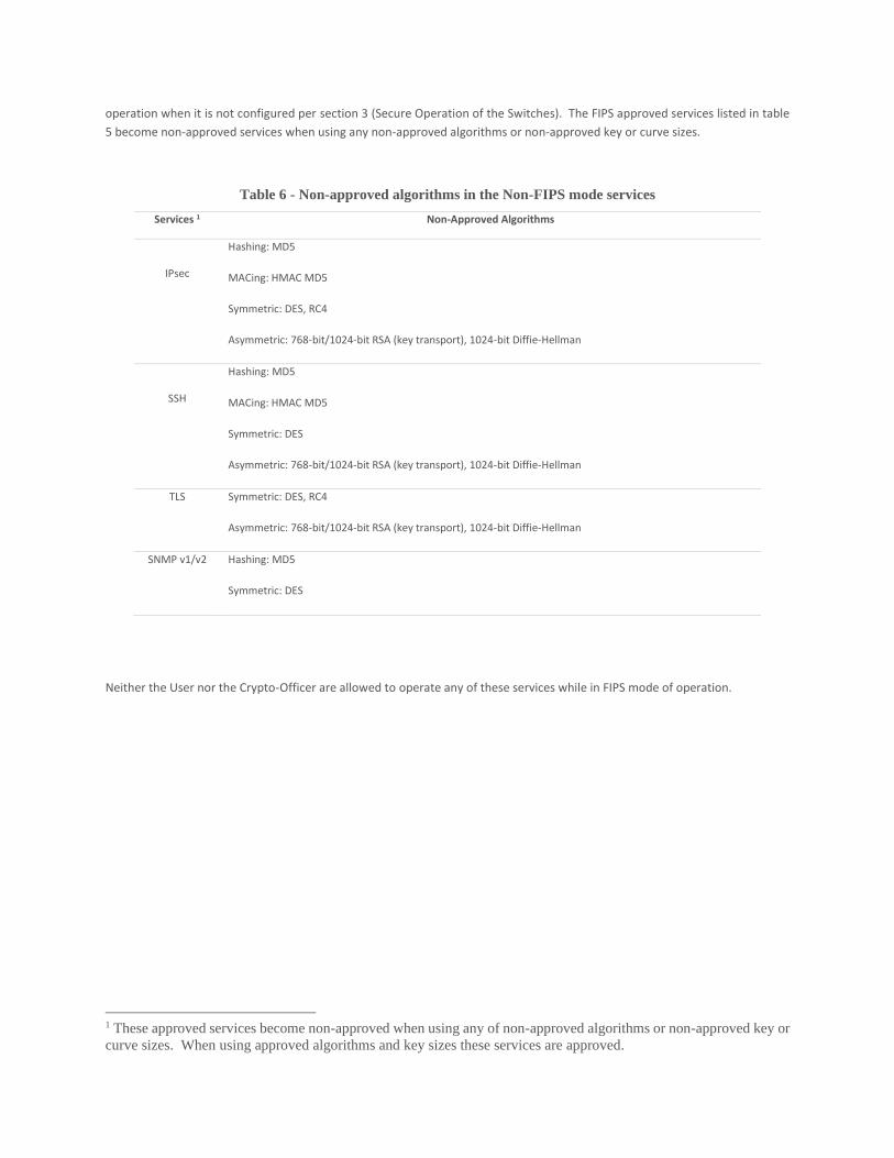
operation when it is not configured per section 3 (Secure Operation of the Switches). The FIPS approved services listed in table
5 become non-approved services when using any non-approved algorithms or non-approved key or curve sizes.
Table 6 - Non-approved algorithms in the Non-FIPS mode services
Services 1 Non-Approved Algorithms
IPsec
Hashing: MD5
MACing: HMAC MD5
Symmetric: DES, RC4
Asymmetric: 768-bit/1024-bit RSA (key transport), 1024-bit Diffie-Hellman
SSH
Hashing: MD5
MACing: HMAC MD5
Symmetric: DES
Asymmetric: 768-bit/1024-bit RSA (key transport), 1024-bit Diffie-Hellman
TLS Symmetric: DES, RC4
Asymmetric: 768-bit/1024-bit RSA (key transport), 1024-bit Diffie-Hellman
SNMP v1/v2 Hashing: MD5
Symmetric: DES
Neither the User nor the Crypto-Officer are allowed to operate any of these services while in FIPS mode of operation.
1 These approved services become non-approved when using any of non-approved algorithms or non-approved key or
curve sizes. When using approved algorithms and key sizes these services are approved.
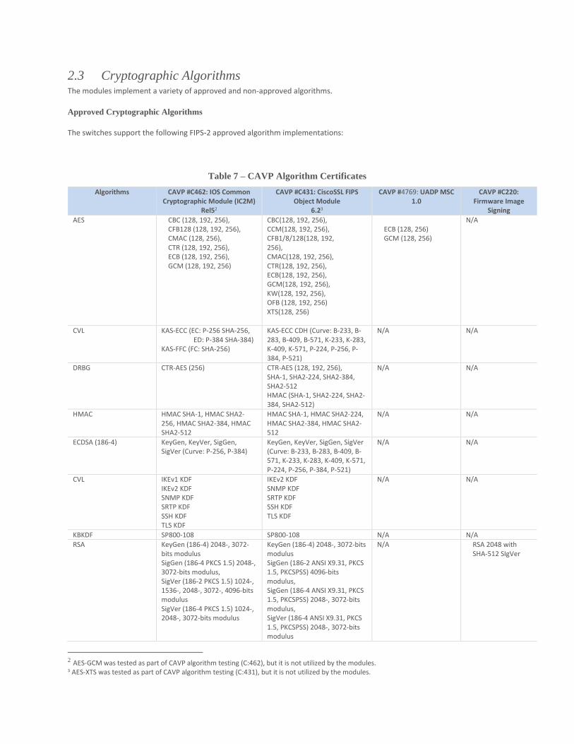
2.3 Cryptographic Algorithms The modules implement a variety of approved and non-approved algorithms.
Approved Cryptographic Algorithms
The switches support the following FIPS-2 approved algorithm implementations:
Table 7 – CAVP Algorithm Certificates
Algorithms CAVP #C462: IOS Common Cryptographic Module (IC2M)
Rel52
CAVP #C431: CiscoSSL FIPS Object Module
6.23
CAVP #4769: UADP MSC 1.0
CAVP #C220: Firmware Image
Signing
AES CBC (128, 192, 256), CFB128 (128, 192, 256), CMAC (128, 256), CTR (128, 192, 256), ECB (128, 192, 256), GCM (128, 192, 256)
CBC(128, 192, 256), CCM(128, 192, 256), CFB1/8/128(128, 192, 256), CMAC(128, 192, 256), CTR(128, 192, 256), ECB(128, 192, 256), GCM(128, 192, 256), KW(128, 192, 256), OFB (128, 192, 256) XTS(128, 256)
ECB (128, 256) GCM (128, 256)
N/A
CVL KAS-ECC (EC: P-256 SHA-256, ED: P-384 SHA-384) KAS-FFC (FC: SHA-256)
KAS-ECC CDH (Curve: B-233, B-283, B-409, B-571, K-233, K-283, K-409, K-571, P-224, P-256, P-384, P-521)
N/A N/A
DRBG CTR-AES (256) CTR-AES (128, 192, 256), SHA-1, SHA2-224, SHA2-384, SHA2-512 HMAC (SHA-1, SHA2-224, SHA2-384, SHA2-512)
N/A N/A
HMAC HMAC SHA-1, HMAC SHA2-256, HMAC SHA2-384, HMAC SHA2-512
HMAC SHA-1, HMAC SHA2-224, HMAC SHA2-384, HMAC SHA2-512
N/A N/A
ECDSA (186-4) KeyGen, KeyVer, SigGen, SigVer (Curve: P-256, P-384)
KeyGen, KeyVer, SigGen, SigVer (Curve: B-233, B-283, B-409, B-571, K-233, K-283, K-409, K-571, P-224, P-256, P-384, P-521)
N/A N/A
CVL IKEv1 KDF IKEv2 KDF SNMP KDF SRTP KDF SSH KDF TLS KDF
IKEv2 KDF SNMP KDF SRTP KDF SSH KDF TLS KDF
N/A N/A
KBKDF SP800-108 SP800-108 N/A N/A
RSA KeyGen (186-4) 2048-, 3072-bits modulus SigGen (186-4 PKCS 1.5) 2048-, 3072-bits modulus, SigVer (186-2 PKCS 1.5) 1024-, 1536-, 2048-, 3072-, 4096-bits modulus SigVer (186-4 PKCS 1.5) 1024-, 2048-, 3072-bits modulus
KeyGen (186-4) 2048-, 3072-bits modulus SigGen (186-2 ANSI X9.31, PKCS 1.5, PKCSPSS) 4096-bits modulus, SigGen (186-4 ANSI X9.31, PKCS 1.5, PKCSPSS) 2048-, 3072-bits modulus, SigVer (186-4 ANSI X9.31, PKCS 1.5, PKCSPSS) 2048-, 3072-bits modulus
N/A RSA 2048 with SHA-512 SIgVer
2 AES-GCM was tested as part of CAVP algorithm testing (C:462), but it is not utilized by the modules. 3 AES-XTS was tested as part of CAVP algorithm testing (C:431), but it is not utilized by the modules.
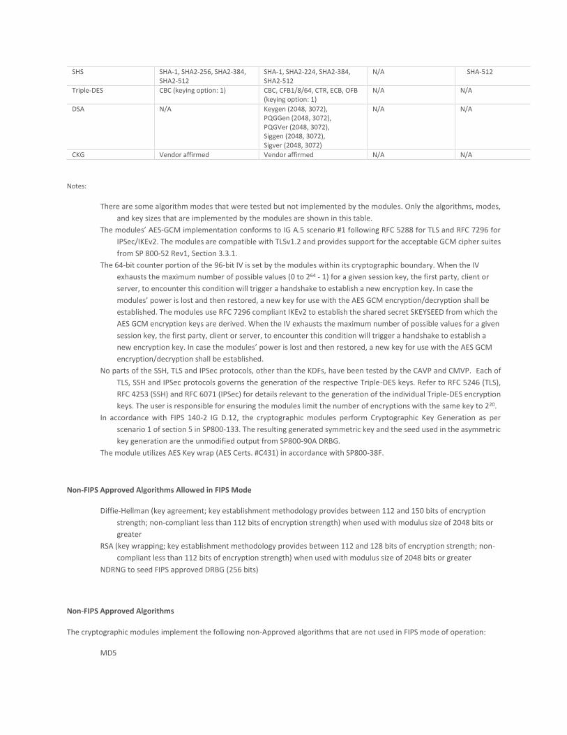
SHS SHA-1, SHA2-256, SHA2-384, SHA2-512
SHA-1, SHA2-224, SHA2-384, SHA2-512
N/A SHA-512
Triple-DES CBC (keying option: 1) CBC, CFB1/8/64, CTR, ECB, OFB (keying option: 1)
N/A N/A
DSA N/A Keygen (2048, 3072), PQGGen (2048, 3072), PQGVer (2048, 3072), Siggen (2048, 3072), Sigver (2048, 3072)
N/A N/A
CKG Vendor affirmed Vendor affirmed N/A N/A
Notes:
There are some algorithm modes that were tested but not implemented by the modules. Only the algorithms, modes,
and key sizes that are implemented by the modules are shown in this table.
The modules’ AES-GCM implementation conforms to IG A.5 scenario #1 following RFC 5288 for TLS and RFC 7296 for
IPSec/IKEv2. The modules are compatible with TLSv1.2 and provides support for the acceptable GCM cipher suites
from SP 800-52 Rev1, Section 3.3.1.
The 64-bit counter portion of the 96-bit IV is set by the modules within its cryptographic boundary. When the IV
exhausts the maximum number of possible values (0 to 264 - 1) for a given session key, the first party, client or
server, to encounter this condition will trigger a handshake to establish a new encryption key. In case the
modules’ power is lost and then restored, a new key for use with the AES GCM encryption/decryption shall be
established. The modules use RFC 7296 compliant IKEv2 to establish the shared secret SKEYSEED from which the
AES GCM encryption keys are derived. When the IV exhausts the maximum number of possible values for a given
session key, the first party, client or server, to encounter this condition will trigger a handshake to establish a
new encryption key. In case the modules’ power is lost and then restored, a new key for use with the AES GCM
encryption/decryption shall be established.
No parts of the SSH, TLS and IPSec protocols, other than the KDFs, have been tested by the CAVP and CMVP. Each of
TLS, SSH and IPSec protocols governs the generation of the respective Triple-DES keys. Refer to RFC 5246 (TLS),
RFC 4253 (SSH) and RFC 6071 (IPSec) for details relevant to the generation of the individual Triple-DES encryption
keys. The user is responsible for ensuring the modules limit the number of encryptions with the same key to 220.
In accordance with FIPS 140-2 IG D.12, the cryptographic modules perform Cryptographic Key Generation as per
scenario 1 of section 5 in SP800-133. The resulting generated symmetric key and the seed used in the asymmetric
key generation are the unmodified output from SP800-90A DRBG.
The module utilizes AES Key wrap (AES Certs. #C431) in accordance with SP800-38F.
Non-FIPS Approved Algorithms Allowed in FIPS Mode
Diffie-Hellman (key agreement; key establishment methodology provides between 112 and 150 bits of encryption
strength; non-compliant less than 112 bits of encryption strength) when used with modulus size of 2048 bits or
greater
RSA (key wrapping; key establishment methodology provides between 112 and 128 bits of encryption strength; non-
compliant less than 112 bits of encryption strength) when used with modulus size of 2048 bits or greater
NDRNG to seed FIPS approved DRBG (256 bits)
Non-FIPS Approved Algorithms
The cryptographic modules implement the following non-Approved algorithms that are not used in FIPS mode of operation:
MD5
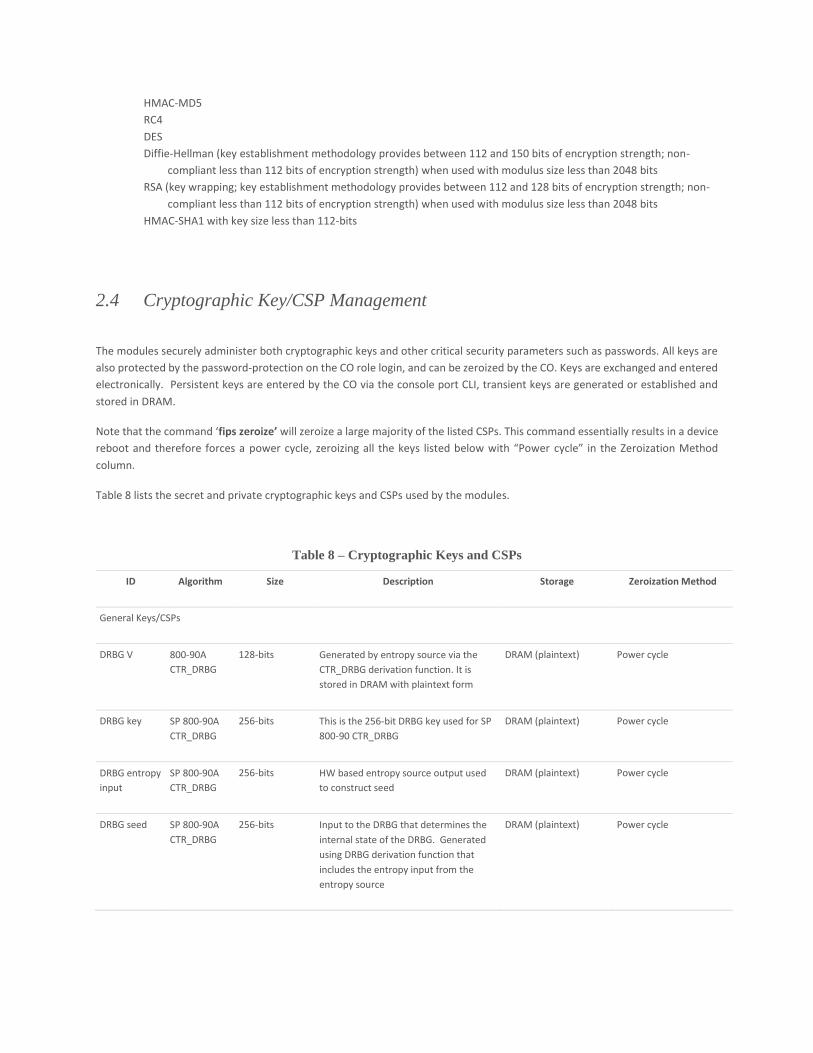
HMAC-MD5
RC4
DES
Diffie-Hellman (key establishment methodology provides between 112 and 150 bits of encryption strength; non-
compliant less than 112 bits of encryption strength) when used with modulus size less than 2048 bits
RSA (key wrapping; key establishment methodology provides between 112 and 128 bits of encryption strength; non-
compliant less than 112 bits of encryption strength) when used with modulus size less than 2048 bits
HMAC-SHA1 with key size less than 112-bits
2.4 Cryptographic Key/CSP Management
The modules securely administer both cryptographic keys and other critical security parameters such as passwords. All keys are
also protected by the password-protection on the CO role login, and can be zeroized by the CO. Keys are exchanged and entered
electronically. Persistent keys are entered by the CO via the console port CLI, transient keys are generated or established and
stored in DRAM.
Note that the command ‘fips zeroize’ will zeroize a large majority of the listed CSPs. This command essentially results in a device
reboot and therefore forces a power cycle, zeroizing all the keys listed below with “Power cycle” in the Zeroization Method
column.
Table 8 lists the secret and private cryptographic keys and CSPs used by the modules.
Table 8 – Cryptographic Keys and CSPs
ID Algorithm Size Description Storage Zeroization Method
General Keys/CSPs
DRBG V 800-90A
CTR_DRBG
128-bits Generated by entropy source via the
CTR_DRBG derivation function. It is
stored in DRAM with plaintext form
DRAM (plaintext) Power cycle
DRBG key SP 800-90A
CTR_DRBG
256-bits This is the 256-bit DRBG key used for SP
800-90 CTR_DRBG
DRAM (plaintext) Power cycle
DRBG entropy
input
SP 800-90A
CTR_DRBG
256-bits HW based entropy source output used
to construct seed
DRAM (plaintext) Power cycle
DRBG seed SP 800-90A
CTR_DRBG
256-bits Input to the DRBG that determines the
internal state of the DRBG. Generated
using DRBG derivation function that
includes the entropy input from the
entropy source
DRAM (plaintext) Power cycle
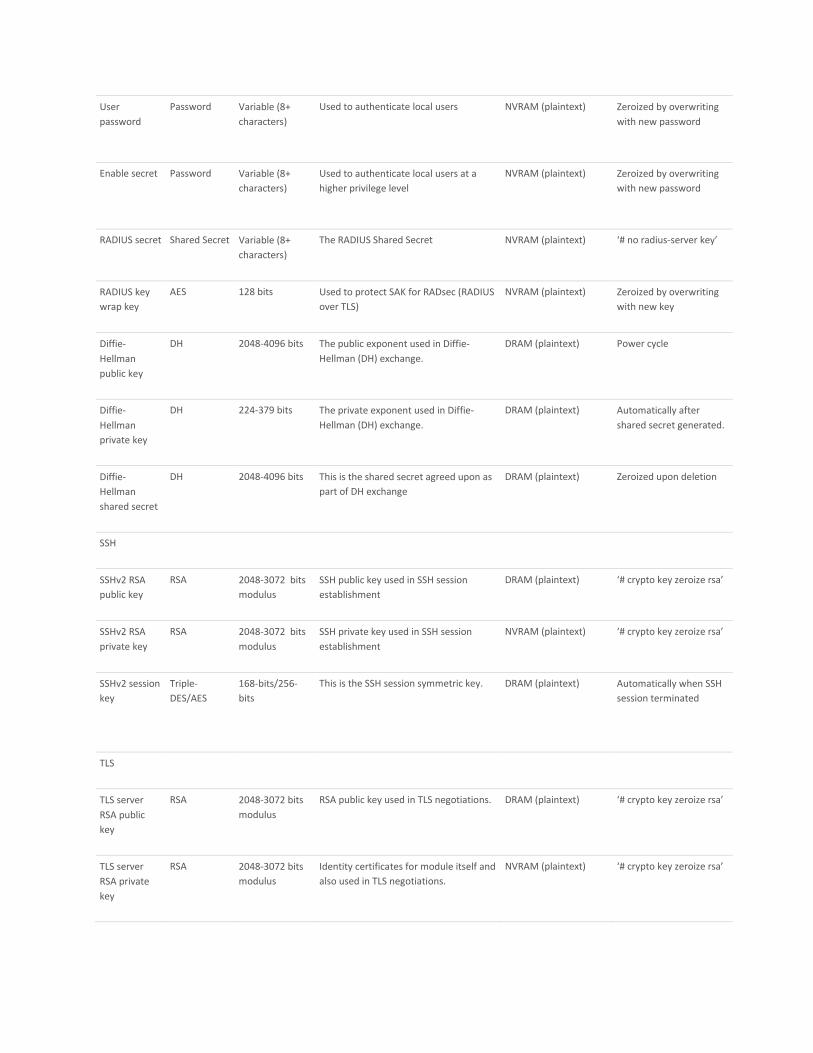
User
password
Password Variable (8+
characters)
Used to authenticate local users NVRAM (plaintext) Zeroized by overwriting
with new password
Enable secret Password Variable (8+
characters)
Used to authenticate local users at a
higher privilege level
NVRAM (plaintext) Zeroized by overwriting
with new password
RADIUS secret Shared Secret Variable (8+
characters)
The RADIUS Shared Secret NVRAM (plaintext) ‘# no radius-server key’
RADIUS key
wrap key
AES 128 bits Used to protect SAK for RADsec (RADIUS
over TLS)
NVRAM (plaintext) Zeroized by overwriting
with new key
Diffie-
Hellman
public key
DH 2048-4096 bits The public exponent used in Diffie-
Hellman (DH) exchange.
DRAM (plaintext) Power cycle
Diffie-
Hellman
private key
DH 224-379 bits The private exponent used in Diffie-
Hellman (DH) exchange.
DRAM (plaintext) Automatically after
shared secret generated.
Diffie-
Hellman
shared secret
DH 2048-4096 bits This is the shared secret agreed upon as
part of DH exchange
DRAM (plaintext) Zeroized upon deletion
SSH
SSHv2 RSA
public key
RSA 2048-3072 bits
modulus
SSH public key used in SSH session
establishment
DRAM (plaintext) ‘# crypto key zeroize rsa’
SSHv2 RSA
private key
RSA 2048-3072 bits
modulus
SSH private key used in SSH session
establishment
NVRAM (plaintext) ‘# crypto key zeroize rsa’
SSHv2 session
key
Triple-
DES/AES
168-bits/256-
bits
This is the SSH session symmetric key. DRAM (plaintext) Automatically when SSH
session terminated
TLS
TLS server
RSA public
key
RSA 2048-3072 bits
modulus
RSA public key used in TLS negotiations. DRAM (plaintext) ‘# crypto key zeroize rsa’
TLS server
RSA private
key
RSA 2048-3072 bits
modulus
Identity certificates for module itself and
also used in TLS negotiations.
NVRAM (plaintext) ‘# crypto key zeroize rsa’
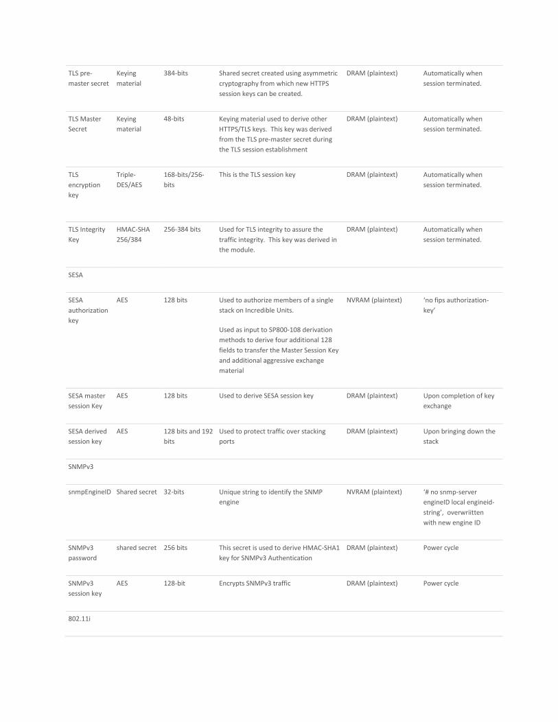
TLS pre-
master secret
Keying
material
384-bits Shared secret created using asymmetric
cryptography from which new HTTPS
session keys can be created.
DRAM (plaintext) Automatically when
session terminated.
TLS Master
Secret
Keying
material
48-bits Keying material used to derive other
HTTPS/TLS keys. This key was derived
from the TLS pre-master secret during
the TLS session establishment
DRAM (plaintext) Automatically when
session terminated.
TLS
encryption
key
Triple-
DES/AES
168-bits/256-
bits
This is the TLS session key DRAM (plaintext) Automatically when
session terminated.
TLS Integrity
Key
HMAC-SHA
256/384
256-384 bits Used for TLS integrity to assure the
traffic integrity. This key was derived in
the module.
DRAM (plaintext) Automatically when
session terminated.
SESA
SESA
authorization
key
AES 128 bits Used to authorize members of a single
stack on Incredible Units.
Used as input to SP800-108 derivation
methods to derive four additional 128
fields to transfer the Master Session Key
and additional aggressive exchange
material
NVRAM (plaintext) ‘no fips authorization-
key’
SESA master
session Key
AES 128 bits Used to derive SESA session key DRAM (plaintext) Upon completion of key
exchange
SESA derived
session key
AES 128 bits and 192
bits
Used to protect traffic over stacking
ports
DRAM (plaintext) Upon bringing down the
stack
SNMPv3
snmpEngineID Shared secret 32-bits Unique string to identify the SNMP
engine
NVRAM (plaintext) ‘# no snmp-server
engineID local engineid-
string’, overwriitten
with new engine ID
SNMPv3
password
shared secret 256 bits This secret is used to derive HMAC-SHA1
key for SNMPv3 Authentication
DRAM (plaintext) Power cycle
SNMPv3
session key
AES 128-bit Encrypts SNMPv3 traffic DRAM (plaintext) Power cycle
802.11i
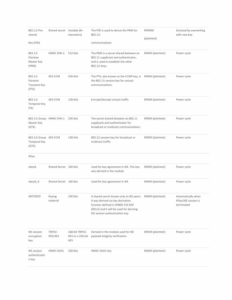
802.11i Pre-
shared
Key (PSK)
Shared secret Variable (8+
characters)
The PSK is used to derive the PMK for
802.11i
communications
NVRAM
(plaintext)
Zeroized by overwriting
with new key
802.11i
Pairwise
Master Key
(PMK)
HMAC SHA-1 512-bits The PMK is a secret shared between an
802.11 supplicant and authenticator,
and is used to establish the other
802.11i keys.
DRAM (plaintext) Power cycle
802.11i
Pairwise
Transient Key
(PTK)
AES-CCM 256-bits The PTK, also known as the CCMP key, is
the 802.11i session key for unicast
communications.
DRAM (plaintext) Power cycle
802.11i
Temporal Key
(TK)
AES-CCM 128-bits Encrypt/decrypt unicast traffic DRAM (plaintext) Power cycle
802.11i Group
Master Key
(GTK)
HMAC SHA-1 256 bits The secret shared between an 802.11
supplicant and authenticator for
broadcast or multicast communications.
DRAM (plaintext) Power cycle
802.11i Group
Temporal Key
(GTK)
AES-CCM 128-bits 802.11i session key for broadcast or
multicast traffic
DRAM (plaintext) Power cycle
IPSec
skeyid Shared Secret 160 bits Used for key agreement in IKE. This key
was derived in the module
DRAM (plaintext) Power cycle
skeyid_d Shared Secret 160 bits Used for key agreement in IKE DRAM (plaintext) Power cycle
SKEYSEED Keying
material
160 bits A shared secret known only to IKE peers.
It was derived via key derivation
function defined in SP800-135 KDF
(IKEv2) and it will be used for deriving
IKE session authentication key.
DRAM (plaintext) Automatically when
IPSec/IKE session is
terminated
IKE session
encryption
key
TRIPLE-
DES/AES
168-bit TRIPLE-
DES or a 256-bit
AES
Derived in the module used for IKE
payload integrity verification
DRAM (plaintext) Power cycle
IKE session
authenticatio
n key
HMAC-SHA1 160 bits HMAC-SHA1 key DRAM (plaintext) Power cycle
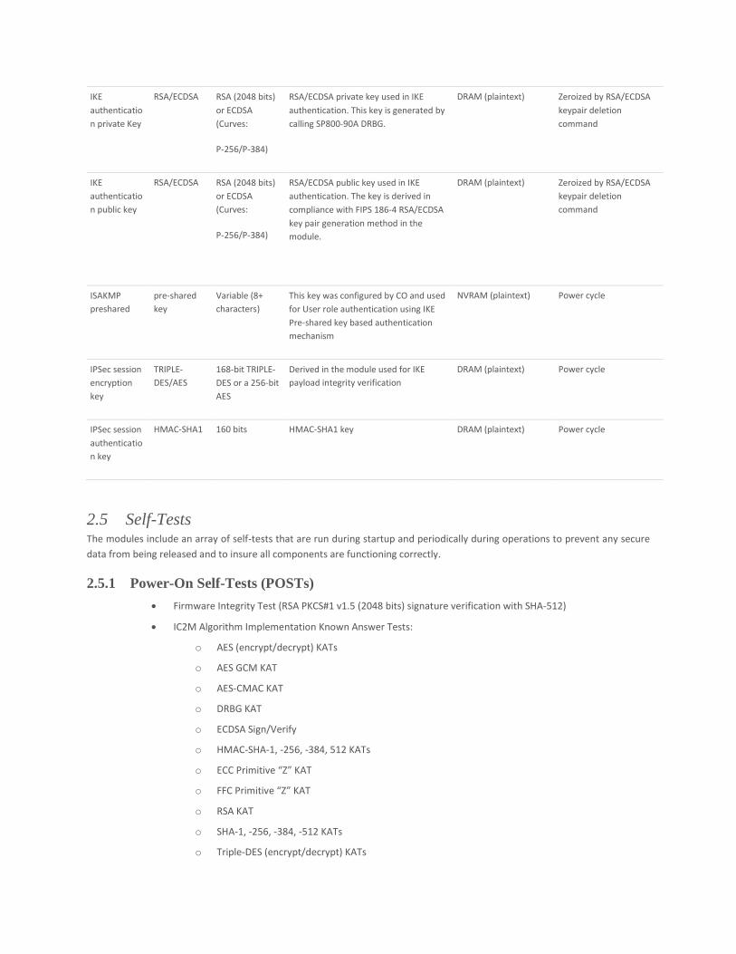
IKE
authenticatio
n private Key
RSA/ECDSA RSA (2048 bits)
or ECDSA
(Curves:
P-256/P-384)
RSA/ECDSA private key used in IKE
authentication. This key is generated by
calling SP800-90A DRBG.
DRAM (plaintext) Zeroized by RSA/ECDSA
keypair deletion
command
IKE
authenticatio
n public key
RSA/ECDSA RSA (2048 bits)
or ECDSA
(Curves:
P-256/P-384)
RSA/ECDSA public key used in IKE
authentication. The key is derived in
compliance with FIPS 186-4 RSA/ECDSA
key pair generation method in the
module.
DRAM (plaintext) Zeroized by RSA/ECDSA
keypair deletion
command
ISAKMP
preshared
pre-shared
key
Variable (8+
characters)
This key was configured by CO and used
for User role authentication using IKE
Pre-shared key based authentication
mechanism
NVRAM (plaintext) Power cycle
IPSec session
encryption
key
TRIPLE-
DES/AES
168-bit TRIPLE-
DES or a 256-bit
AES
Derived in the module used for IKE
payload integrity verification
DRAM (plaintext) Power cycle
IPSec session
authenticatio
n key
HMAC-SHA1 160 bits HMAC-SHA1 key DRAM (plaintext) Power cycle
2.5 Self-Tests The modules include an array of self-tests that are run during startup and periodically during operations to prevent any secure
data from being released and to insure all components are functioning correctly.
2.5.1 Power-On Self-Tests (POSTs)
• Firmware Integrity Test (RSA PKCS#1 v1.5 (2048 bits) signature verification with SHA-512)
• IC2M Algorithm Implementation Known Answer Tests:
o AES (encrypt/decrypt) KATs
o AES GCM KAT
o AES-CMAC KAT
o DRBG KAT
o ECDSA Sign/Verify
o HMAC-SHA-1, -256, -384, 512 KATs
o ECC Primitive “Z” KAT
o FFC Primitive “Z” KAT
o RSA KAT
o SHA-1, -256, -384, -512 KATs
o Triple-DES (encrypt/decrypt) KATs
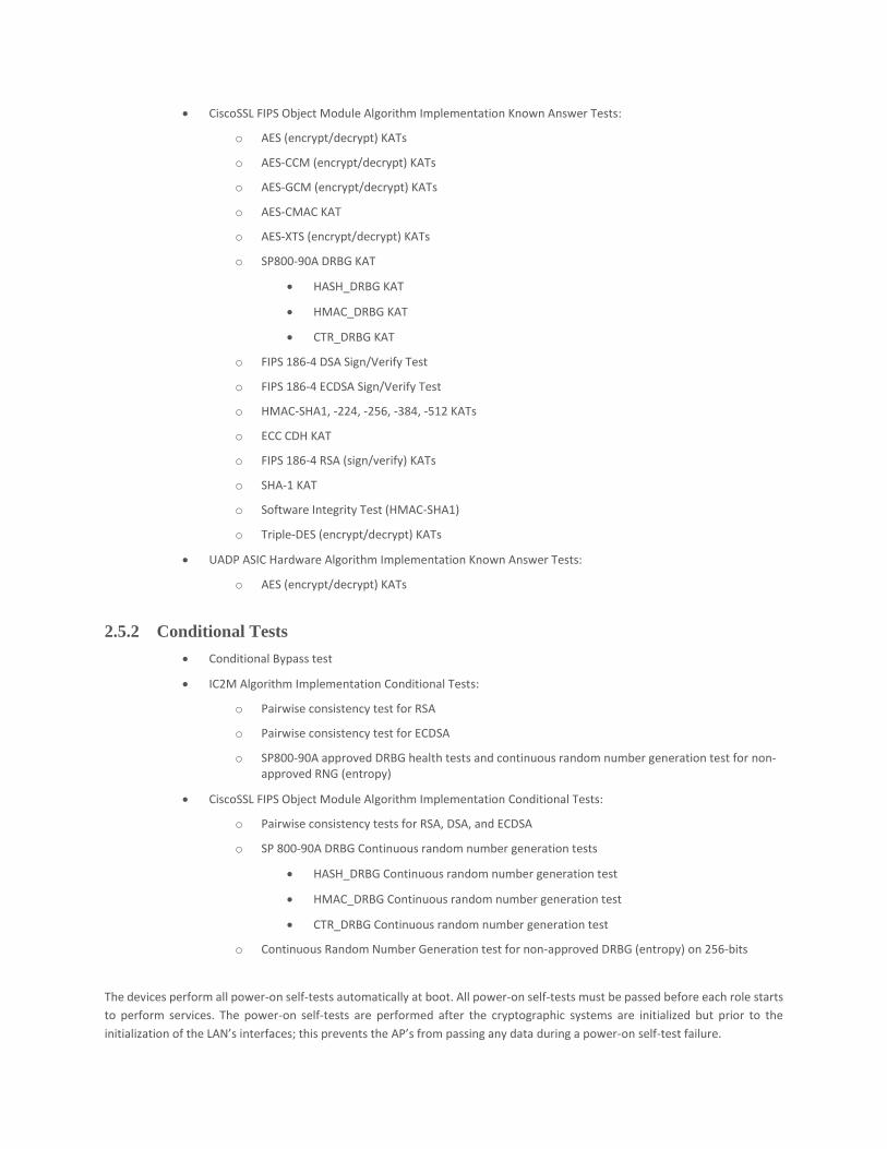
• CiscoSSL FIPS Object Module Algorithm Implementation Known Answer Tests:
o AES (encrypt/decrypt) KATs
o AES-CCM (encrypt/decrypt) KATs
o AES-GCM (encrypt/decrypt) KATs
o AES-CMAC KAT
o AES-XTS (encrypt/decrypt) KATs
o SP800-90A DRBG KAT
• HASH_DRBG KAT
• HMAC_DRBG KAT
• CTR_DRBG KAT
o FIPS 186-4 DSA Sign/Verify Test
o FIPS 186-4 ECDSA Sign/Verify Test
o HMAC-SHA1, -224, -256, -384, -512 KATs
o ECC CDH KAT
o FIPS 186-4 RSA (sign/verify) KATs
o SHA-1 KAT
o Software Integrity Test (HMAC-SHA1)
o Triple-DES (encrypt/decrypt) KATs
• UADP ASIC Hardware Algorithm Implementation Known Answer Tests:
o AES (encrypt/decrypt) KATs
2.5.2 Conditional Tests
• Conditional Bypass test
• IC2M Algorithm Implementation Conditional Tests:
o Pairwise consistency test for RSA
o Pairwise consistency test for ECDSA
o SP800-90A approved DRBG health tests and continuous random number generation test for non-approved RNG (entropy)
• CiscoSSL FIPS Object Module Algorithm Implementation Conditional Tests:
o Pairwise consistency tests for RSA, DSA, and ECDSA
o SP 800-90A DRBG Continuous random number generation tests
• HASH_DRBG Continuous random number generation test
• HMAC_DRBG Continuous random number generation test
• CTR_DRBG Continuous random number generation test
o Continuous Random Number Generation test for non-approved DRBG (entropy) on 256-bits
The devices perform all power-on self-tests automatically at boot. All power-on self-tests must be passed before each role starts
to perform services. The power-on self-tests are performed after the cryptographic systems are initialized but prior to the
initialization of the LAN’s interfaces; this prevents the AP’s from passing any data during a power-on self-test failure.
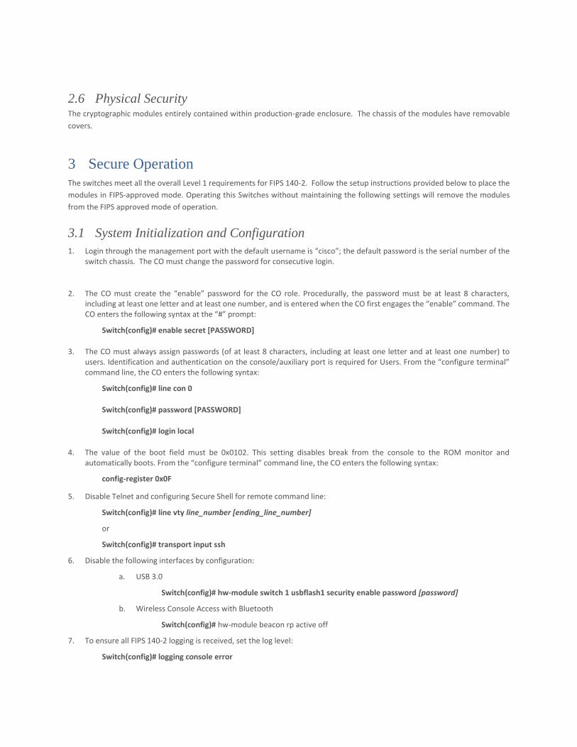
2.6 Physical Security The cryptographic modules entirely contained within production-grade enclosure. The chassis of the modules have removable
covers.
3 Secure Operation The switches meet all the overall Level 1 requirements for FIPS 140-2. Follow the setup instructions provided below to place the
modules in FIPS-approved mode. Operating this Switches without maintaining the following settings will remove the modules
from the FIPS approved mode of operation.
3.1 System Initialization and Configuration
1. Login through the management port with the default username is “cisco”; the default password is the serial number of the switch chassis. The CO must change the password for consecutive login.
2. The CO must create the “enable” password for the CO role. Procedurally, the password must be at least 8 characters, including at least one letter and at least one number, and is entered when the CO first engages the “enable” command. The CO enters the following syntax at the “#” prompt:
Switch(config)# enable secret [PASSWORD]
3. The CO must always assign passwords (of at least 8 characters, including at least one letter and at least one number) to users. Identification and authentication on the console/auxiliary port is required for Users. From the “configure terminal” command line, the CO enters the following syntax:
Switch(config)# line con 0
Switch(config)# password [PASSWORD]
Switch(config)# login local
4. The value of the boot field must be 0x0102. This setting disables break from the console to the ROM monitor and automatically boots. From the “configure terminal” command line, the CO enters the following syntax:
config-register 0x0F
5. Disable Telnet and configuring Secure Shell for remote command line:
Switch(config)# line vty line_number [ending_line_number]
or
Switch(config)# transport input ssh
6. Disable the following interfaces by configuration:
a. USB 3.0
Switch(config)# hw-module switch 1 usbflash1 security enable password [password]
b. Wireless Console Access with Bluetooth
Switch(config)# hw-module beacon rp active off
7. To ensure all FIPS 140-2 logging is received, set the log level:
Switch(config)# logging console error

8. The CO enables secure stacking (SESA) but configuring the Authorization key: Switch(config)# fips authorization-key <128 bit, i.e, 16 hex byte key>
9. The CO may configure the modules to use RADsec for authentication. If the modules are configured to use RADsec, the Crypto Officer must define RADIUS or shared secret keys that are at least 8 characters long, including at least one letter and at least one number.
10. The CO shall only assign users to a privilege level 1 (the default).
11. The CO shall not assign a command to any privilege level other than its default.