Embed Size (px)
Citation preview
Cisco Catalyst
Virtual Switching SystemBRKCRS-3035
Shawn WargoTechnical Marketing Engineer
© 2015 Cisco and/or its affiliates. All rights reserved.BRKCRS-3035 Cisco Public
Key Objectives
• Understand the Key Benefits of VSS
Network Design
• Understand the VSS Architecture and
how a VSS behaves differently than a
Standalone system
• Understand common VSS deployment
Best Practices
© 2015 Cisco and/or its affiliates. All rights reserved.BRKCRS-3035 Cisco Public
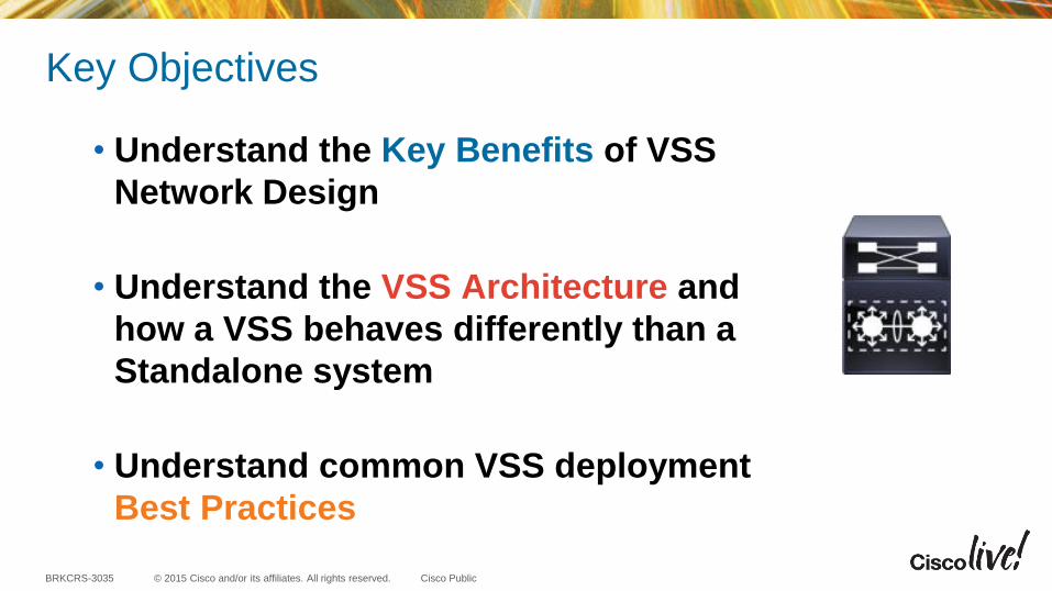
Presentation Legend
3
Reference Materials
Standalone (Multilayer) Switch
Virtual Switching System (VSS)
Key Points to Remember
Layer 2 Link
Layer 3 Link
© 2015 Cisco and/or its affiliates. All rights reserved.BRKCRS-3035 Cisco Public
Agenda
• Why VSS?
• VSS Conversion and VSS Architecture
• Hardware and Software Requirements
• VSS High Availability and Dual Active
• VSS Redundant Supervisors
• VSL Design Considerations
• VSS Software Upgrades
• Best Practices and Summary
4
Why VSS ?
© 2015 Cisco and/or its affiliates. All rights reserved.BRKCRS-3035 Cisco Public 6
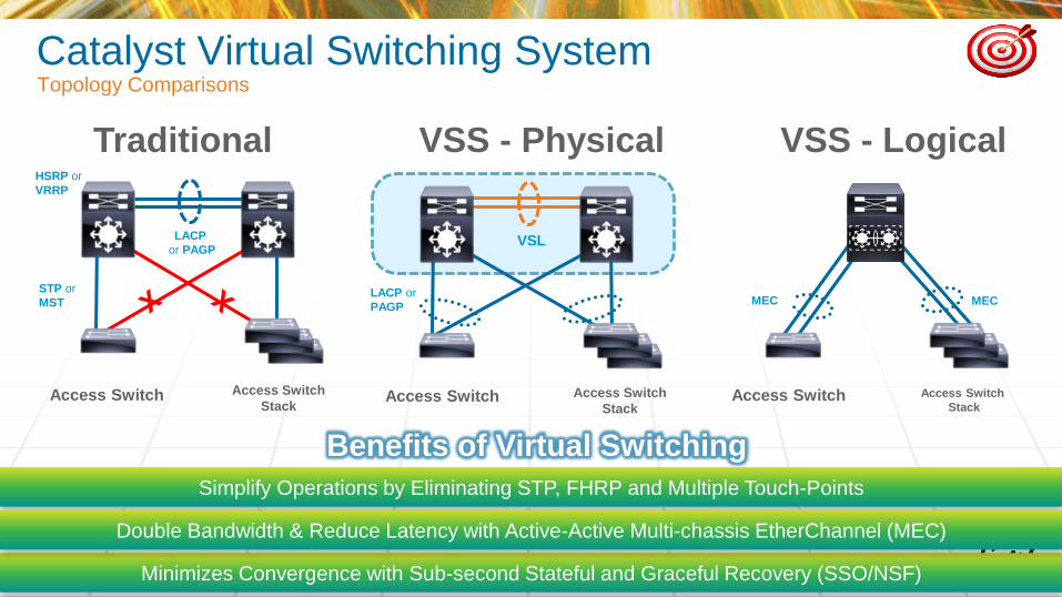
Simplify Operations by Eliminating STP, FHRP and Multiple Touch-Points
Minimizes Convergence with Sub-second Stateful and Graceful Recovery (SSO/NSF)
Double Bandwidth & Reduce Latency with Active-Active Multi-chassis EtherChannel (MEC)
Benefits of Virtual Switching
Catalyst Virtual Switching SystemTopology Comparisons
Traditional
Access Switch
LACP
or PAGP
STP or
MST
HSRP or
VRRP
Access Switch
Stack
VSS - Physical
LACP or
PAGP
VSL
Access Switch Access Switch
Stack
VSS - Logical
Access Switch
Stack
MEC
Access Switch
MEC
© 2015 Cisco and/or its affiliates. All rights reserved.BRKCRS-3035 Cisco Public
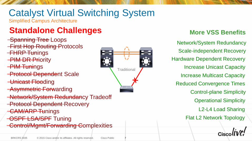
Catalyst Virtual Switching SystemSimplified Campus Architecture
Simplified and Scalable Network Design– Centralized and Redundant System Architecture
– Single Unified Management Per Layer
– Multi-Terabit Distributed Switching Capacity
Deterministic Network Performance– Inter-Chassis System and Network-level Redundancy
– Protocol and Scale Independent Resiliency
Supported Platforms:– 6800X – Sup2T
– 6500E – Sup2T / Sup720
– 4500E – Sup7E / Sup8E
– 4500X
PIM DR Priority
Spanning Tree LoopsFirst Hop Routing ProtocolsFHRP Tunings
PIM Tunings
Protocol Dependent Scale
Unicast Flooding
Asymmetric Forwarding
Protocol Dependent Recovery
Network/System Redundancy Tradeoff
CAM/ARP Tunings
OSPF LSA/SPF TuningControl/Mgmt/Forwarding Complexities
Standalone Challenges
Increase Unicast Capacity
Increase Multicast Capacity
Control-plane Simplicity
Operational Simplicity
Flat L2 Network Topology
Hardware Dependent Recovery
Network/System Redundancy
L2-L4 Load Sharing
Scale-independent Recovery
Reduced Convergence Times
More VSS Benefits
VSS
Traditional
7
© 2015 Cisco and/or its affiliates. All rights reserved.BRKCRS-3035 Cisco Public
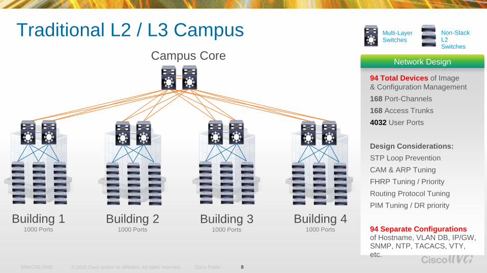
Building 11000 Ports
Building 21000 Ports
Building 31000 Ports
Building 41000 Ports
Campus Core
94 Total Devices of Image
& Configuration Management
168 Port-Channels
168 Access Trunks
4032 User Ports
Design Considerations:
STP Loop Prevention
CAM & ARP Tuning
FHRP Tuning / Priority
Routing Protocol Tuning
PIM Tuning / DR priority
94 Separate Configurations of Hostname, VLAN DB, IP/GW, SNMP, NTP, TACACS, VTY, etc.
Network Design
Traditional L2 / L3 Campus Multi-Layer Switches
Non-Stack L2 Switches
8
© 2015 Cisco and/or its affiliates. All rights reserved.BRKCRS-3035 Cisco Public
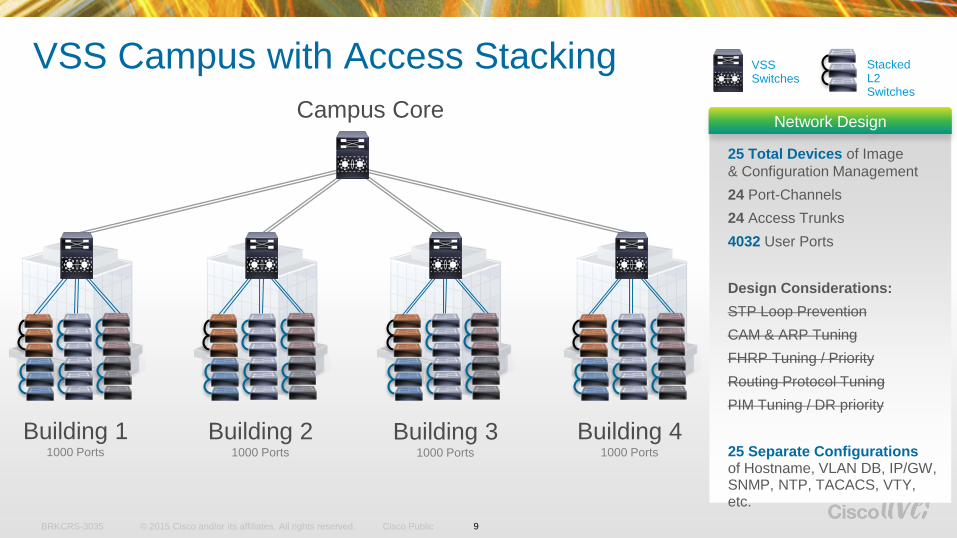
VSS
VSS Campus with Access Stacking
25 Total Devices of Image
& Configuration Management
24 Port-Channels
24 Access Trunks
4032 User Ports
Design Considerations:
STP Loop Prevention
CAM & ARP Tuning
FHRP Tuning / Priority
Routing Protocol Tuning
PIM Tuning / DR priority
25 Separate Configurations of Hostname, VLAN DB, IP/GW, SNMP, NTP, TACACS, VTY, etc.
Network Design
VSS Switches
Stacked L2 Switches
Campus Core
Building 11000 Ports
Building 21000 Ports
Building 31000 Ports
Building 41000 Ports
9
© 2015 Cisco and/or its affiliates. All rights reserved.BRKCRS-3035 Cisco Public
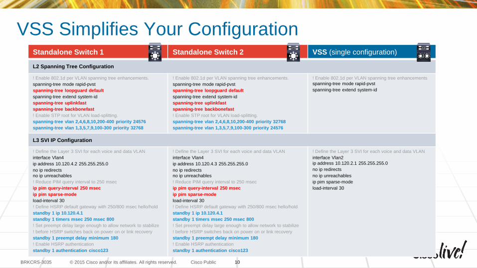
VSS Simplifies Your ConfigurationStandalone Switch 1 Standalone Switch 2 VSS (single configuration)
L2 Spanning Tree Configuration
! Enable 802.1d per VLAN spanning tree enhancements.
spanning-tree mode rapid-pvst
spanning-tree loopguard default
spanning-tree extend system-id
spanning-tree uplinkfast
spanning-tree backbonefast
! Enable STP root for VLAN load-splitting.
spanning-tree vlan 2,4,6,8,10,200-400 priority 24576
spanning-tree vlan 1,3,5,7,9,100-300 priority 32768
! Enable 802.1d per VLAN spanning tree enhancements.
spanning-tree mode rapid-pvst
spanning-tree loopguard default
spanning-tree extend system-id
spanning-tree uplinkfast
spanning-tree backbonefast
! Enable STP root for VLAN load-splitting.
spanning-tree vlan 2,4,6,8,10,200-400 priority 32768
spanning-tree vlan 1,3,5,7,9,100-300 priority 24576
! Enable 802.1d per VLAN spanning tree enhancements
spanning-tree mode rapid-pvst
spanning-tree extend system-id
L3 SVI IP Configuration
! Define the Layer 3 SVI for each voice and data VLAN
interface Vlan4
ip address 10.120.4.2 255.255.255.0
no ip redirects
no ip unreachables
! Reduce PIM query interval to 250 msec
ip pim query-interval 250 msec
ip pim sparse-mode
load-interval 30
! Define HSRP default gateway with 250/800 msec hello/hold
standby 1 ip 10.120.4.1
standby 1 timers msec 250 msec 800
! Set preempt delay large enough to allow network to stabilize
! before HSRP switches back on power on or link recovery
standby 1 preempt delay minimum 180
! Enable HSRP authentication
standby 1 authentication cisco123
! Define the Layer 3 SVI for each voice and data VLAN
interface Vlan4
ip address 10.120.4.3 255.255.255.0
no ip redirects
no ip unreachables
! Reduce PIM query interval to 250 msec
ip pim query-interval 250 msec
ip pim sparse-mode
load-interval 30
! Define HSRP default gateway with 250/800 msec hello/hold
standby 1 ip 10.120.4.1
standby 1 timers msec 250 msec 800
! Set preempt delay large enough to allow network to stabilize
! before HSRP switches back on power on or link recovery
standby 1 preempt delay minimum 180
! Enable HSRP authentication
standby 1 authentication cisco123
! Define the Layer 3 SVI for each voice and data VLAN
interface Vlan2
ip address 10.120.2.1 255.255.255.0
no ip redirects
no ip unreachables
ip pim sparse-mode
load-interval 30
10

VSS Conversion Process
© 2015 Cisco and/or its affiliates. All rights reserved.BRKCRS-3035 Cisco Public
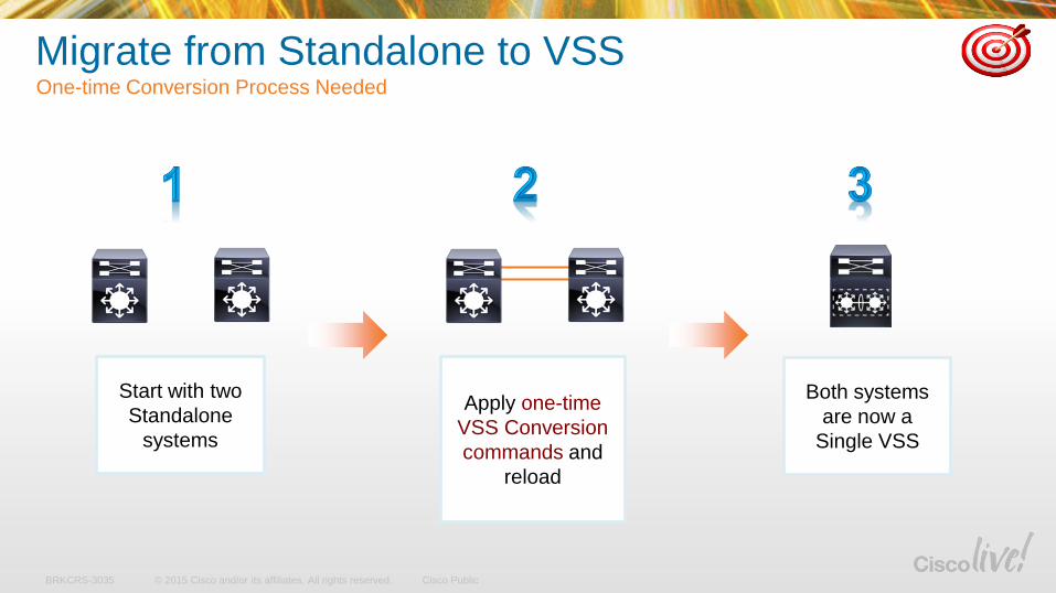
Migrate from Standalone to VSSOne-time Conversion Process Needed
Start with two
Standalone
systems
Both systems
are now a
Single VSS
Apply one-time
VSS Conversion
commands and
reload
© 2015 Cisco and/or its affiliates. All rights reserved.BRKCRS-3035 Cisco Public
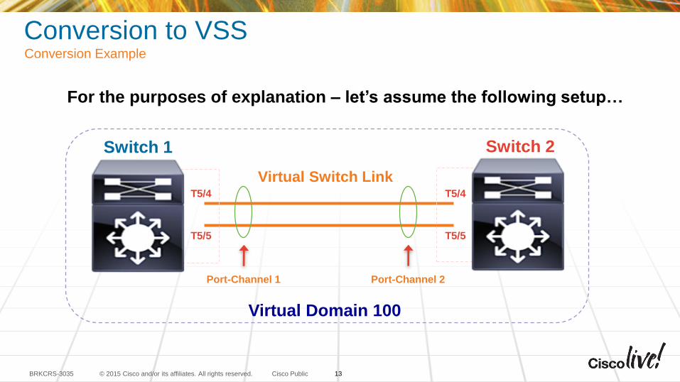
Conversion to VSSConversion Example
For the purposes of explanation – let’s assume the following setup…
Virtual Switch LinkT5/4
T5/5
T5/4
T5/5
Port-Channel 1 Port-Channel 2
Virtual Domain 100
Switch 1 Switch 2
13
© 2015 Cisco and/or its affiliates. All rights reserved.BRKCRS-3035 Cisco Public
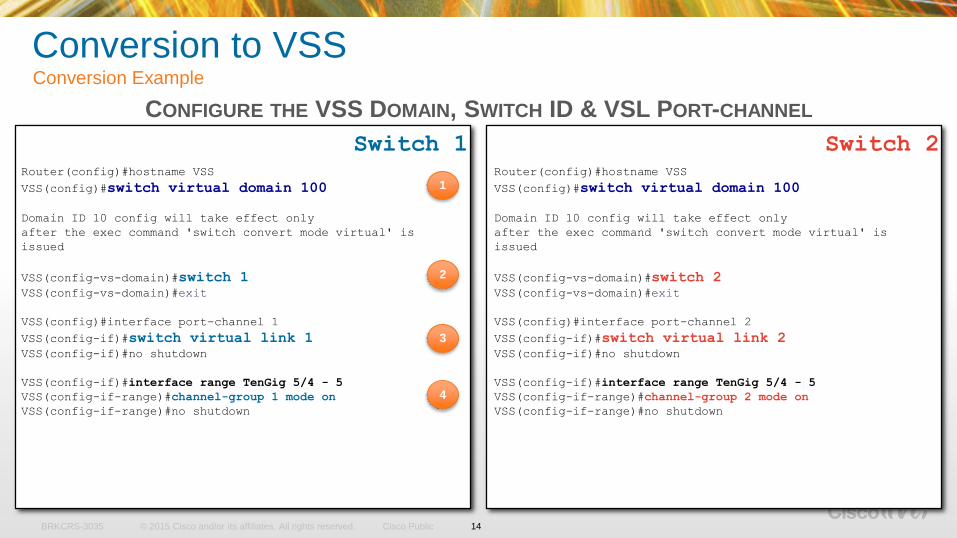
Conversion to VSS Conversion Example
CONFIGURE THE VSS DOMAIN, SWITCH ID & VSL PORT-CHANNEL
Switch 2Router(config)#hostname VSS
VSS(config)#switch virtual domain 100
Domain ID 10 config will take effect only
after the exec command 'switch convert mode virtual' is
issued
VSS(config-vs-domain)#switch 1VSS(config-vs-domain)#exit
VSS(config)#interface port-channel 1
VSS(config-if)#switch virtual link 1VSS(config-if)#no shutdown
VSS(config-if)#interface range TenGig 5/4 - 5
VSS(config-if-range)#channel-group 1 mode on
VSS(config-if-range)#no shutdown
Router(config)#hostname VSS
VSS(config)#switch virtual domain 100
Domain ID 10 config will take effect only
after the exec command 'switch convert mode virtual' is
issued
VSS(config-vs-domain)#switch 2VSS(config-vs-domain)#exit
VSS(config)#interface port-channel 2
VSS(config-if)#switch virtual link 2VSS(config-if)#no shutdown
VSS(config-if)#interface range TenGig 5/4 - 5
VSS(config-if-range)#channel-group 2 mode on
VSS(config-if-range)#no shutdown
Switch 1
1
2
3
14
4
© 2015 Cisco and/or its affiliates. All rights reserved.BRKCRS-3035 Cisco Public
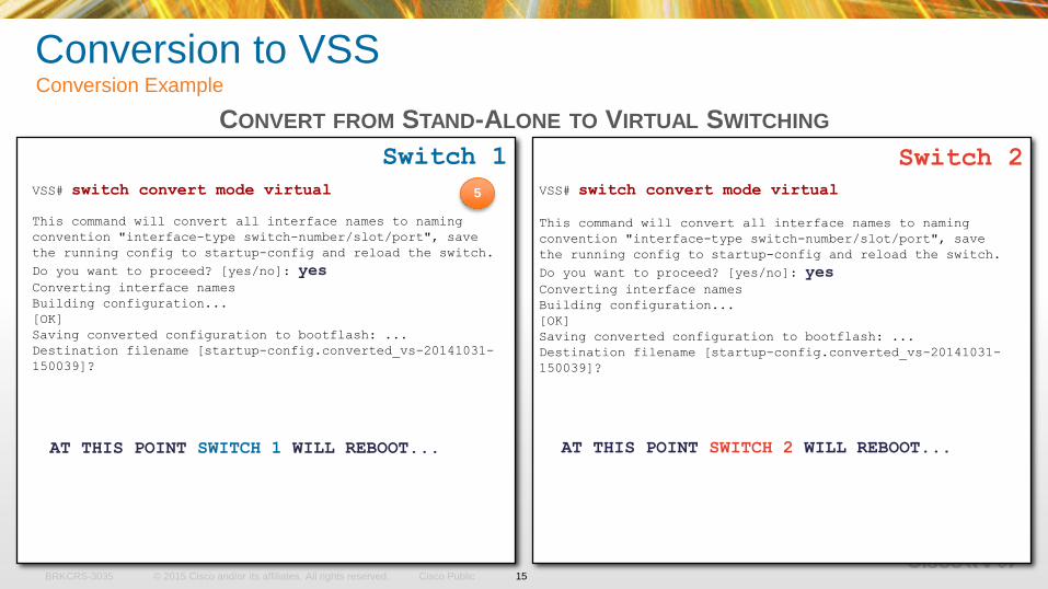
VSS# switch convert mode virtual
This command will convert all interface names to naming
convention "interface-type switch-number/slot/port", save
the running config to startup-config and reload the switch.
Do you want to proceed? [yes/no]: yesConverting interface names
Building configuration...
[OK]
Saving converted configuration to bootflash: ...
Destination filename [startup-config.converted_vs-20141031-
150039]?
Switch 2
VSS# switch convert mode virtual
This command will convert all interface names to naming
convention "interface-type switch-number/slot/port", save
the running config to startup-config and reload the switch.
Do you want to proceed? [yes/no]: yesConverting interface names
Building configuration...
[OK]
Saving converted configuration to bootflash: ...
Destination filename [startup-config.converted_vs-20141031-
150039]?
Switch 1
5
AT THIS POINT SWITCH 1 WILL REBOOT... AT THIS POINT SWITCH 2 WILL REBOOT...
CONVERT FROM STAND-ALONE TO VIRTUAL SWITCHING
15
Conversion to VSS Conversion Example
© 2015 Cisco and/or its affiliates. All rights reserved.BRKCRS-3035 Cisco Public
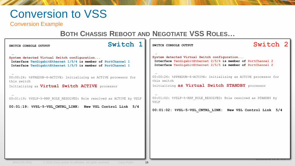
SWITCH CONSOLE OUTPUT
…
System detected Virtual Switch configuration...
Interface TenGigabitEthernet 1/5/4 is member of PortChannel 1
Interface TenGigabitEthernet 1/5/5 is member of PortChannel 1
…
00:00:26: %PFREDUN-6-ACTIVE: Initializing as ACTIVE processor for
this switch
Initializing as Virtual Switch ACTIVE processor
…
00:01:19: %VSLP-5-RRP_ROLE_RESOLVED: Role resolved as ACTIVE by VSLP
00:01:19: %VSL-5-VSL_CNTRL_LINK: New VSL Control Link 5/4
SWITCH CONSOLE OUTPUT
…
System detected Virtual Switch configuration...
Interface TenGigabitEthernet 2/5/4 is member of PortChannel 2
Interface TenGigabitEthernet 2/5/5 is member of PortChannel 2
…
00:00:26: %PFREDUN-6-ACTIVE: Initializing as ACTIVE processor for
this switch
Initializing as Virtual Switch STANDBY processor
…
00:01:02: %VSLP-5-RRP_ROLE_RESOLVED: Role resolved as STANDBY by
VSLP
00:01:02: %VSL-5-VSL_CNTRL_LINK: New VSL Control Link 5/4
Switch 1 Switch 2
BOTH CHASSIS REBOOT AND NEGOTIATE VSS ROLES…
16
Conversion to VSS Conversion Example
© 2015 Cisco and/or its affiliates. All rights reserved.BRKCRS-3035 Cisco Public
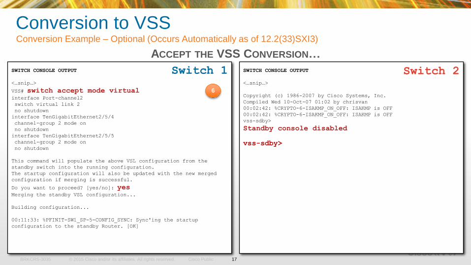
SWITCH CONSOLE OUTPUT
<…snip…>
VSS# switch accept mode virtualinterface Port-channel2
switch virtual link 2
no shutdown
interface TenGigabitEthernet2/5/4
channel-group 2 mode on
no shutdown
interface TenGigabitEthernet2/5/5
channel-group 2 mode on
no shutdown
This command will populate the above VSL configuration from the
standby switch into the running configuration.
The startup configuration will also be updated with the new merged
configuration if merging is successful.
Do you want to proceed? [yes/no]: yesMerging the standby VSL configuration...
Building configuration...
00:11:33: %PFINIT-SW1_SP-5-CONFIG_SYNC: Sync'ing the startup
configuration to the standby Router. [OK]
SWITCH CONSOLE OUTPUT
<…snip…>
Copyright (c) 1986-2007 by Cisco Systems, Inc.
Compiled Wed 10-Oct-07 01:02 by chrisvan
00:02:42: %CRYPTO-6-ISAKMP_ON_OFF: ISAKMP is OFF
00:02:42: %CRYPTO-6-ISAKMP_ON_OFF: ISAKMP is OFF
vss-sdby>
Standby console disabled
vss-sdby>
Switch 2Switch 1
Conversion to VSSConversion Example – Optional (Occurs Automatically as of 12.2(33)SXI3)
6
ACCEPT THE VSS CONVERSION…
17
© 2015 Cisco and/or its affiliates. All rights reserved.BRKCRS-3035 Cisco Public
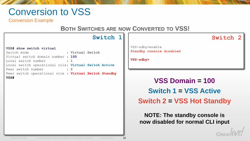
VSS Domain = 100
Switch 1 = VSS Active
Switch 2 = VSS Hot Standby
NOTE: The standby console is
now disabled for normal CLI input
VSS-sdby>enable
Standby console disabled
VSS-sdby>
Switch 2Switch 1
VSS# show switch virtual
Switch mode : Virtual Switch
Virtual switch domain number : 100
Local switch number : 1
Local switch operational role: Virtual Switch Active
Peer switch number : 2
Peer switch operational role : Virtual Switch Standby
VSS#
18
BOTH SWITCHES ARE NOW CONVERTED TO VSS!
Conversion to VSS Conversion Example
© 2015 Cisco and/or its affiliates. All rights reserved.BRKCRS-3035 Cisco Public
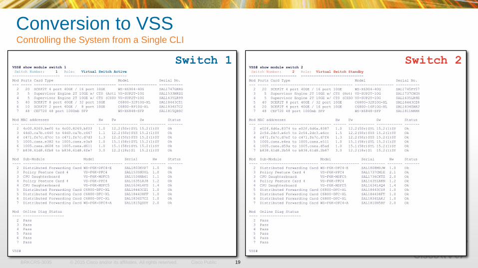
Switch 2Switch 1VSS# show module switch 1
Switch Number: 1 Role: Virtual Switch Active
---------------------- -----------------------------
Mod Ports Card Type Model Serial No.
--- ----- -------------------------------------- ------------------ -----------
2 20 DCEF2T 4 port 40GE / 16 port 10GE WS-X6904-40G SAL1747GKRG
3 5 Supervisor Engine 2T 10GE w/ CTS (Acti VS-SUP2T-10G SAL1533M8ZG
4 5 Supervisor Engine 2T 10GE w/ CTS (CSSO VS-SUP2T-10G SAL1635LR99
5 40 DCEF2T 8 port 40GE / 32 port 10GE C6800-32P10G-XL SAL18443CZ1
6 10 DCEF2T 2 port 40GE / 8 port 10GE C6800-8P10G-XL SAL1834Z7C2
7 48 CEF720 48 port 1000mb SFP WS-X6848-SFP SAL1815QBSC
Mod MAC addresses Hw Fw Sw Status
--- ---------------------------------- ------ ------------ ------------ -------
2 4c00.8269.bef0 to 4c00.8269.bf03 1.0 12.2(50r)SYL 15.2(1)SY Ok
3 44d3.ca7b.c440 to 44d3.ca7b.c447 1.1 12.2(50r)SYS 15.2(1)SY Ok
4 c471.fe7c.d7cc to c471.fe7c.d7d3 1.3 12.2(50r)SYS 15.2(1)SY Ok
5 1005.caea.e382 to 1005.caea.e3a9 1.0 15.1(58r)SYL 15.2(1)SY Ok
6 1005.caea.d608 to 1005.caea.d611 1.0 15.1(58r)SYL 15.2(1)SY Ok
7 b838.61d8.6fb8 to b838.61d8.6fe7 3.0 12.2(18r)S1 15.2(1)SY Ok
Mod Sub-Module Model Serial Hw Status
---- --------------------------- ------------------ ----------- ------- -------
2 Distributed Forwarding Card WS-F6K-DFC4-E SAL1803KVP7 1.0 Ok
3 Policy Feature Card 4 VS-F6K-PFC4 SAL1535NU0L 1.0 Ok
3 CPU Daughterboard VS-F6K-MSFC5 SAL1534NA61 1.1 Ok
4 Policy Feature Card 4 VS-F6K-PFC4 SAL1635LRJ8 1.2 Ok
4 CPU Daughterboard VS-F6K-MSFC5 SAL1634L4FS 1.4 Ok
5 Distributed Forwarding Card C6800-DFC-XL SAL18443CZ1 1.0 Ok
5 Distributed Forwarding Card C6800-DFC-XL SAL184438FF 1.0 Ok
6 Distributed Forwarding Card C6800-DFC-XL SAL1834Z7C2 1.0 Ok
7 Distributed Forwarding Card WS-F6K-DFC4-A SAL1815QDDY 2.0 Ok
Mod Online Diag Status
---- -------------------
2 Pass
3 Pass
4 Pass
5 Pass
6 Pass
7 Pass
VSS#
Conversion to VSSControlling the System from a Single CLI
VSS# show module switch 2
Switch Number: 2 Role: Virtual Switch Standby
---------------------- -----------------------------
Mod Ports Card Type Model Serial No.
--- ----- -------------------------------------- ------------------ -----------
2 20 DCEF2T 4 port 40GE / 16 port 10GE WS-X6904-40G SAL1745FY57
3 5 Supervisor Engine 2T 10GE w/ CTS (Hot) VS-SUP2T-10G SAL1737CNCH
4 5 Supervisor Engine 2T 10GE w/ CTS (CSSO VS-SUP2T-10G SAL1635LR9E
5 40 DCEF2T 8 port 40GE / 32 port 10GE C6800-32P10G-XL SAL18443CZ8
6 20 DCEF2T 4 port 40GE / 16 port 10GE C6800-16P10G-XL SAL1834ZAKJ
7 48 CEF720 48 port 1000mb SFP WS-X6848-SFP SAL1811NKKK
Mod MAC addresses Hw Fw Sw Status
--- ---------------------------------- ------ ------------ ------------ -------
2 e02f.6d6a.8374 to e02f.6d6a.8387 1.0 12.2(50r)SYL 15.2(1)SY Ok
3 2c54.2dc3.e6c5 to 2c54.2dc3.e6cc 1.5 12.2(50r)SYS 15.2(1)SY Ok
4 c471.fe7c.d7ef to c471.fe7c.d7f6 1.3 12.2(50r)SYS 15.2(1)SY Ok
5 1005.caea.e4ea to 1005.caea.e511 1.0 15.1(58r)SYL 15.2(1)SY Ok
6 1005.caea.d59a to 1005.caea.d5ad 1.0 15.1(58r)SYL 15.2(1)SY Ok
7 b838.61d8.2b58 to b838.61d8.2b87 3.0 12.2(18r)S1 15.2(1)SY Ok
Mod Sub-Module Model Serial Hw Status
---- --------------------------- ------------------ ----------- ------- -------
2 Distributed Forwarding Card WS-F6K-DFC4-E SAL1808MDJW 1.0 Ok
3 Policy Feature Card 4 VS-F6K-PFC4 SAL1737CM1E 2.1 Ok
3 CPU Daughterboard VS-F6K-MSFC5 SAL1736CKTZ 2.0 Ok
4 Policy Feature Card 4 VS-F6K-PFC4 SAL1635LRKN 1.2 Ok
4 CPU Daughterboard VS-F6K-MSFC5 SAL1634L4Q4 1.4 Ok
5 Distributed Forwarding Card C6800-DFC-XL SAL18443CZ8 1.0 Ok
5 Distributed Forwarding Card C6800-DFC-XL SAL184438FT 1.0 Ok
6 Distributed Forwarding Card C6800-DFC-XL SAL1834ZAKJ 1.0 Ok
7 Distributed Forwarding Card WS-F6K-DFC4-A SAL1810N58F 2.0 Ok
Mod Online Diag Status
---- -------------------
2 Pass
3 Pass
4 Pass
5 Pass
6 Pass
7 Pass
VSS#
19
© 2015 Cisco and/or its affiliates. All rights reserved.BRKCRS-3035 Cisco Public
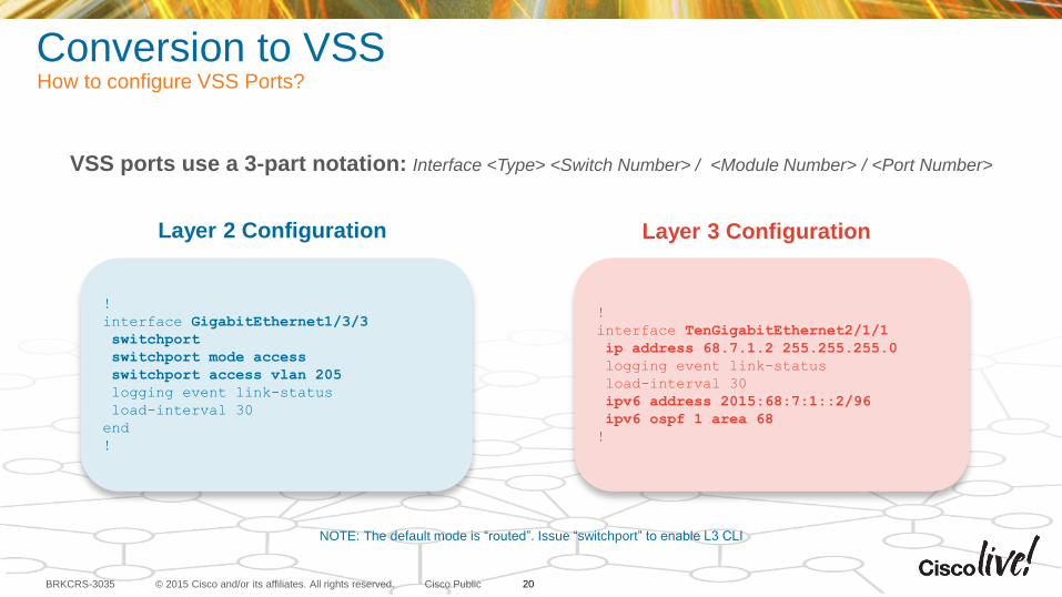
Conversion to VSSHow to configure VSS Ports?
VSS ports use a 3-part notation: Interface <Type> <Switch Number> / <Module Number> / <Port Number>
Layer 2 Configuration
!
interface GigabitEthernet1/3/3
switchport
switchport mode access
switchport access vlan 205
logging event link-status
load-interval 30
end
!
Layer 3 Configuration
!
interface TenGigabitEthernet2/1/1
ip address 68.7.1.2 255.255.255.0
logging event link-status
load-interval 30
ipv6 address 2015:68:7:1::2/96
ipv6 ospf 1 area 68
!
NOTE: The default mode is “routed”. Issue “switchport” to enable L3 CLI
20
VSS Architecture
© 2015 Cisco and/or its affiliates. All rights reserved.BRKCRS-3035 Cisco Public
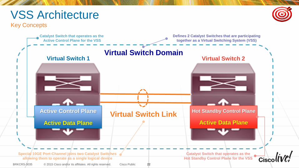
VSS ArchitectureKey Concepts
Virtual Switch Domain
Virtual Switch Link
Special 10GE Port-Channel joins two Catalyst Switches
allowing them to operate as a single logical device
Active Control Plane
Active Data Plane
Hot Standby Control Plane
Active Data Plane
Virtual Switch 1 Virtual Switch 2
Catalyst Switch that operates as the
Hot Standby Control Plane for the VSS
Defines 2 Catalyst Switches that are participating
together as a Virtual Switching System (VSS)
Catalyst Switch that operates as the
Active Control Plane for the VSS
22
© 2015 Cisco and/or its affiliates. All rights reserved.BRKCRS-3035 Cisco Public
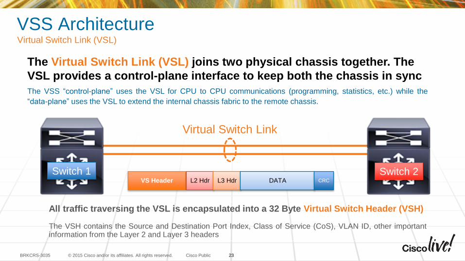
VSS ArchitectureVirtual Switch Link (VSL)
The Virtual Switch Link (VSL) joins two physical chassis together. The
VSL provides a control-plane interface to keep both the chassis in sync
The VSS “control-plane” uses the VSL for CPU to CPU communications (programming, statistics, etc.) while the
“data-plane” uses the VSL to extend the internal chassis fabric to the remote chassis.
All traffic traversing the VSL is encapsulated into a 32 Byte Virtual Switch Header (VSH)
The VSH contains the Source and Destination Port Index, Class of Service (CoS), VLAN ID, other importantinformation from the Layer 2 and Layer 3 headers
Virtual Switch Link
VS Header L2 Hdr L3 Hdr DATA CRC
23
Switch 1 Switch 2
© 2015 Cisco and/or its affiliates. All rights reserved.BRKCRS-3035 Cisco Public
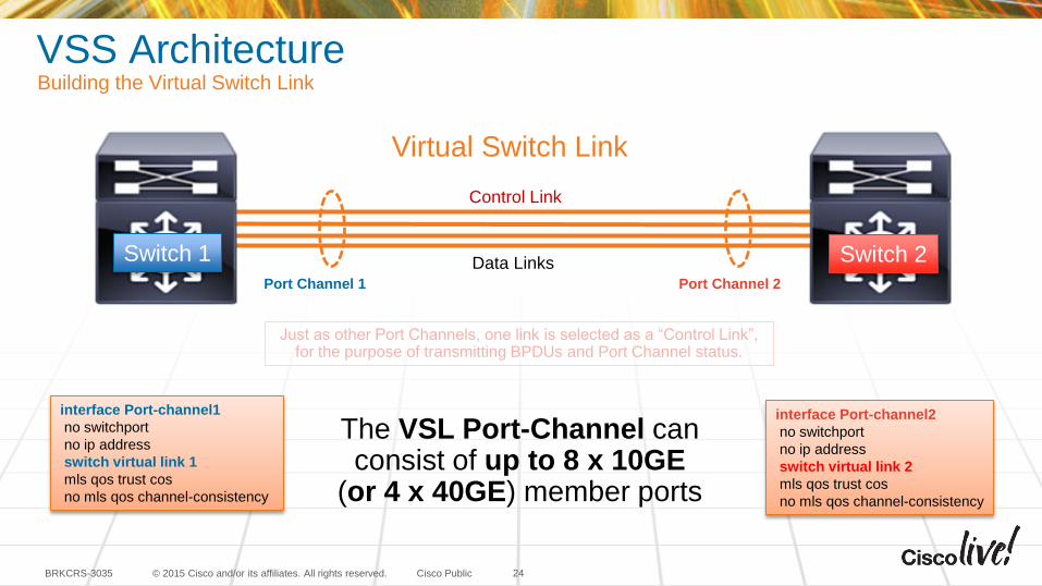
VSS ArchitectureBuilding the Virtual Switch Link
24
interface Port-channel1
no switchport
no ip address
switch virtual link 1
mls qos trust cos
no mls qos channel-consistency
Port Channel 1 Port Channel 2
Control Link
Data Links
Virtual Switch Link
Switch 1 Switch 2
interface Port-channel2
no switchport
no ip address
switch virtual link 2
mls qos trust cos
no mls qos channel-consistency
Just as other Port Channels, one link is selected as a “Control Link”, for the purpose of transmitting BPDUs and Port Channel status.
The VSL Port-Channel can consist of up to 8 x 10GE
(or 4 x 40GE) member ports
© 2015 Cisco and/or its affiliates. All rights reserved.BRKCRS-3035 Cisco Public 25
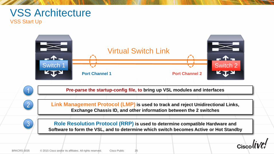
Pre-parse the startup-config file, to bring up VSL modules and interfaces1
Link Management Protocol (LMP) is used to track and reject Unidirectional Links,
Exchange Chassis ID, and other information between the 2 switches 2
Role Resolution Protocol (RRP) is used to determine compatible Hardware and
Software to form the VSL, and to determine which switch becomes Active or Hot Standby3
Virtual Switch Link
Port Channel 1 Port Channel 2
VSS ArchitectureVSS Start Up
Switch 1 Switch 2
© 2015 Cisco and/or its affiliates. All rights reserved.BRKCRS-3035 Cisco Public 26
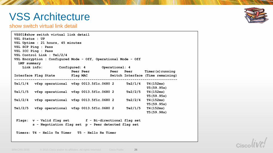
VSS01#show switch virtual link detail
VSL Status : UP
VSL Uptime : 21 hours, 45 minutes
VSL SCP Ping : Pass
VSL ICC Ping : Pass
VSL Control Link : Te1/2/4
VSL Encryption : Configured Mode - Off, Operational Mode - Off
LMP summary
Link info: Configured: 4 Operational: 4
Peer Peer Peer Peer Timer(s)running
Interface Flag State Flag MAC Switch Interface (Time remaining)
--------------------------------------------------------------------------------
Te1/1/4 vfsp operational vfsp 0013.5f1c.0680 2 Te2/1/4 T4(152ms)
T5(59.95s)
Te1/1/5 vfsp operational vfsp 0013.5f1c.0680 2 Te2/2/5 T4(152ms)
T5(59.95s)
Te1/2/4 vfsp operational vfsp 0013.5f1c.0680 2 Te2/2/4 T4(152ms)
T5(59.95s)
Te1/2/5 vfsp operational vfsp 0013.5f1c.0680 2 Te2/1/5 T4(152ms)
T5(59.98s)
Flags: v - Valid flag set f - Bi-directional flag set
s - Negotiation flag set p - Peer detected flag set
Timers: T4 - Hello Tx Timer T5 - Hello Rx Timer
VSS Architectureshow switch virtual link detail
© 2015 Cisco and/or its affiliates. All rights reserved.BRKCRS-3035 Cisco Public
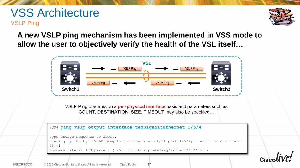
VSS ArchitectureVSLP Ping
A new VSLP ping mechanism has been implemented in VSS mode to
allow the user to objectively verify the health of the VSL itself…
VSL
Switch1 Switch2
VSLP Ping
VSS# ping vslp output interface tenGigabitEthernet 1/5/4
Type escape sequence to abort.
Sending 5, 100-byte VSLP ping to peer-sup via output port 1/5/4, timeout is 2 seconds:
!!!!!
Success rate is 100 percent (5/5), round-trip min/avg/max = 12/12/16 ms
VSLP Ping operates on a per-physical interface basis and parameters such as
COUNT, DESTINATION, SIZE, TIMEOUT may also be specified…
VSLP Ping
VSLP PingVSLP Ping
27
© 2015 Cisco and/or its affiliates. All rights reserved.BRKCRS-3035 Cisco Public
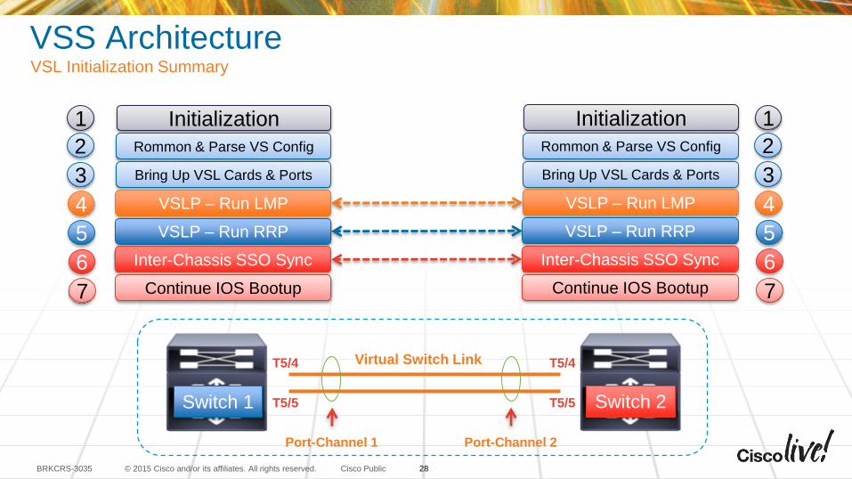
VSS ArchitectureVSL Initialization Summary
Virtual Switch LinkT5/4
T5/5
T5/4
T5/5
Port-Channel 1 Port-Channel 2
Initialization
Rommon & Parse VS Config
Bring Up VSL Cards & Ports
VSLP – Run LMP
VSLP – Run RRP
Inter-Chassis SSO Sync
Continue IOS Bootup
Initialization
Rommon & Parse VS Config
Bring Up VSL Cards & Ports
VSLP – Run LMP
VSLP – Run RRP
Inter-Chassis SSO Sync
Continue IOS Bootup
1
2
3
4
5
6
7
1
2
3
4
5
6
7
28
Switch 1 Switch 2
© 2015 Cisco and/or its affiliates. All rights reserved.BRKCRS-3035 Cisco Public
VSS ArchitectureConfiguration Consistency Check
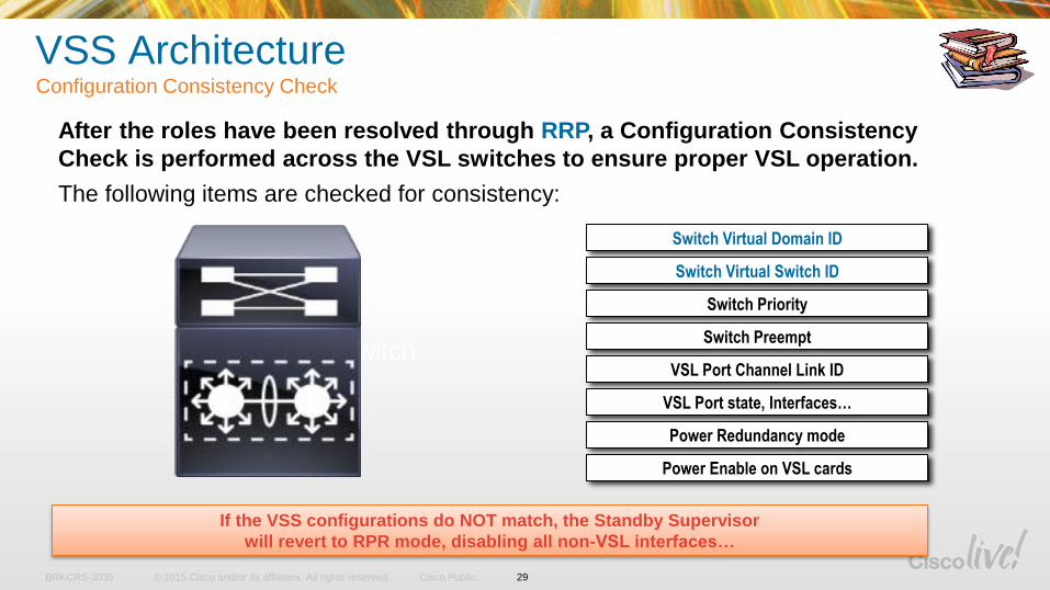
After the roles have been resolved through RRP, a Configuration Consistency
Check is performed across the VSL switches to ensure proper VSL operation.
The following items are checked for consistency:
Switch Virtual Domain ID
Switch Virtual Switch ID
Switch Priority
Switch Preempt
VSL Port Channel Link ID
VSL Port state, Interfaces…
Power Redundancy mode
Power Enable on VSL cards
If the VSS configurations do NOT match, the Standby Supervisor
will revert to RPR mode, disabling all non-VSL interfaces…
Virtual Switch
29
© 2015 Cisco and/or its affiliates. All rights reserved.BRKCRS-3035 Cisco Public
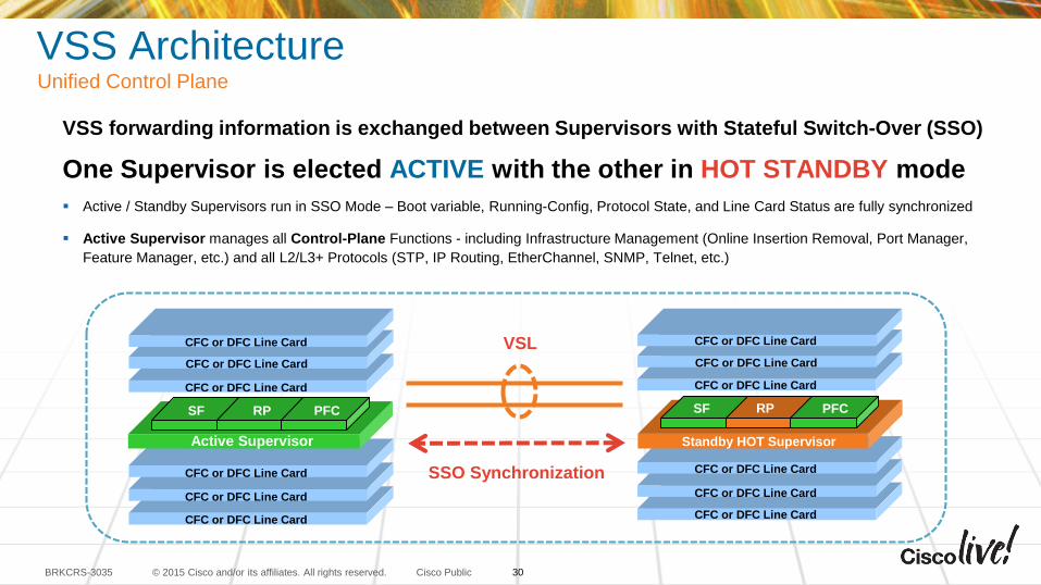
VSS ArchitectureUnified Control Plane
VSS forwarding information is exchanged between Supervisors with Stateful Switch-Over (SSO)
One Supervisor is elected ACTIVE with the other in HOT STANDBY mode
Active / Standby Supervisors run in SSO Mode – Boot variable, Running-Config, Protocol State, and Line Card Status are fully synchronized
Active Supervisor manages all Control-Plane Functions - including Infrastructure Management (Online Insertion Removal, Port Manager,
Feature Manager, etc.) and all L2/L3+ Protocols (STP, IP Routing, EtherChannel, SNMP, Telnet, etc.)
VSL
CFC or DFC Line Card
CFC or DFC Line Card
CFC or DFC Line Card
CFC or DFC Line Card
CFC or DFC Line Card
Standby HOT Supervisor
SF RP PFC
CFC or DFC Line Card
Active Supervisor
SF RP PFC
CFC or DFC Line Card
CFC or DFC Line Card
CFC or DFC Line Card
CFC or DFC Line Card
CFC or DFC Line Card
CFC or DFC Line Card
SSO Synchronization
30
© 2015 Cisco and/or its affiliates. All rights reserved.BRKCRS-3035 Cisco Public
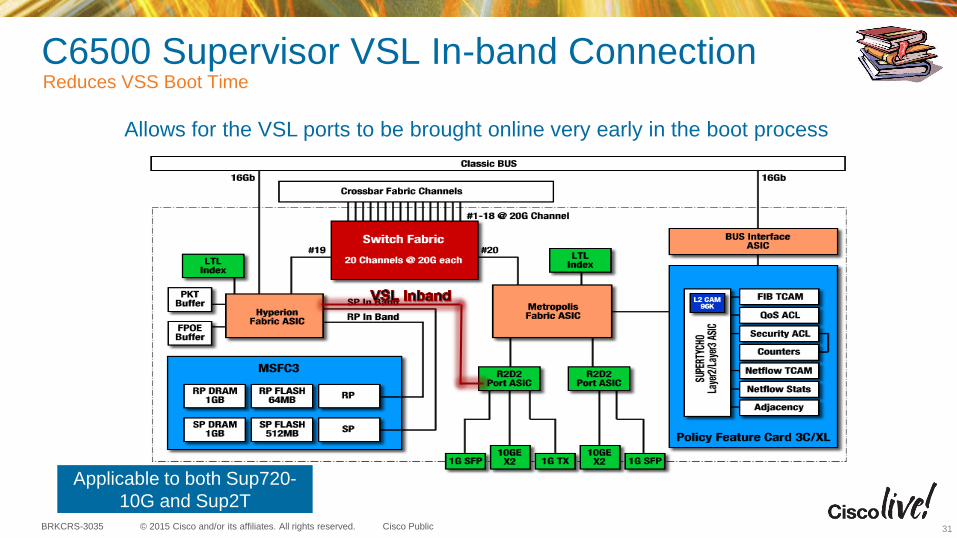
C6500 Supervisor VSL In-band ConnectionReduces VSS Boot Time
31
Allows for the VSL ports to be brought online very early in the boot process
Applicable to both Sup720-
10G and Sup2T
© 2015 Cisco and/or its affiliates. All rights reserved.BRKCRS-3035 Cisco Public
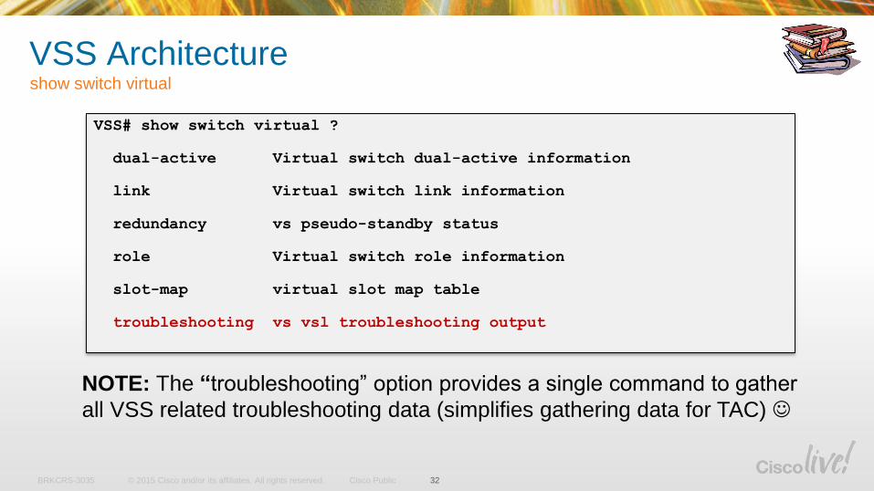
VSS Architectureshow switch virtual
32
VSS# show switch virtual ?
dual-active Virtual switch dual-active information
link Virtual switch link information
redundancy vs pseudo-standby status
role Virtual switch role information
slot-map virtual slot map table
troubleshooting vs vsl troubleshooting output
NOTE: The “troubleshooting” option provides a single command to gather
all VSS related troubleshooting data (simplifies gathering data for TAC)
© 2015 Cisco and/or its affiliates. All rights reserved.BRKCRS-3035 Cisco Public
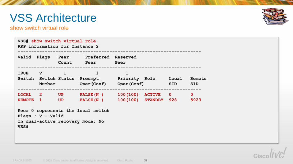
VSS Architectureshow switch virtual role
33
VSS# show switch virtual role
RRP information for Instance 2
--------------------------------------------------------------------
Valid Flags Peer Preferred Reserved
Count Peer Peer
--------------------------------------------------------------------
TRUE V 1 1 1
Switch Switch Status Preempt Priority Role Local Remote
Number Oper(Conf) Oper(Conf) SID SID
--------------------------------------------------------------------
LOCAL 2 UP FALSE(N ) 100(100) ACTIVE 0 0
REMOTE 1 UP FALSE(N ) 100(100) STANDBY 928 5923
Peer 0 represents the local switch
Flags : V - Valid
In dual-active recovery mode: No
VSS#
© 2015 Cisco and/or its affiliates. All rights reserved.BRKCRS-3035 Cisco Public
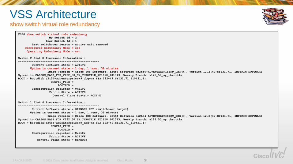
VSS Architectureshow switch virtual role redundancy
34
VSS# show switch virtual role redundancy
My Switch Id = 2
Peer Switch Id = 1
Last switchover reason = active unit removed
Configured Redundancy Mode = sso
Operating Redundancy Mode = sso
Switch 2 Slot 8 Processor Information :
-----------------------------------------------
Current Software state = ACTIVE
Uptime in current state = 1 day, 1 hour, 39 minutes
Image Version = Cisco IOS Software, s2t54 Software (s2t54-ADVENTERPRISEK9_DBG-M), Version 12.2(49)SY131.71, INTERIM SOFTWARE
Synced to CARSON_BASE_FOR_V122_50_SY_THROTTLE_121610_101313, Weekly Branch: v122_50_sy_throttle
BOOT = bootdisk:s2t54-adventerprisek9_dbg-mz.SSA.122-49.SY131.71_110421,1;
CONFIG_FILE =
BOOTLDR =
Configuration register = 0x2102
Fabric State = ACTIVE
Control Plane State = ACTIVE
Switch 1 Slot 6 Processor Information :
-----------------------------------------------
Current Software state = STANDBY HOT (switchover target)
Uptime in current state = 1 day, 1 hour, 35 minutes
Image Version = Cisco IOS Software, s2t54 Software (s2t54-ADVENTERPRISEK9_DBG-M), Version 12.2(49)SY131.71, INTERIM SOFTWARE
Synced to CARSON_BASE_FOR_V122_50_SY_THROTTLE_121610_101313, Weekly Branch: v122_50_sy_throttle
BOOT = bootdisk:s2t54-adventerprisek9_dbg-mz.SSA.122-49.SY131.71_110421,1;
CONFIG_FILE =
BOOTLDR =
Configuration register = 0x2102
Fabric State = ACTIVE
Control Plane State = STANDBY
© 2015 Cisco and/or its affiliates. All rights reserved.BRKCRS-3035 Cisco Public
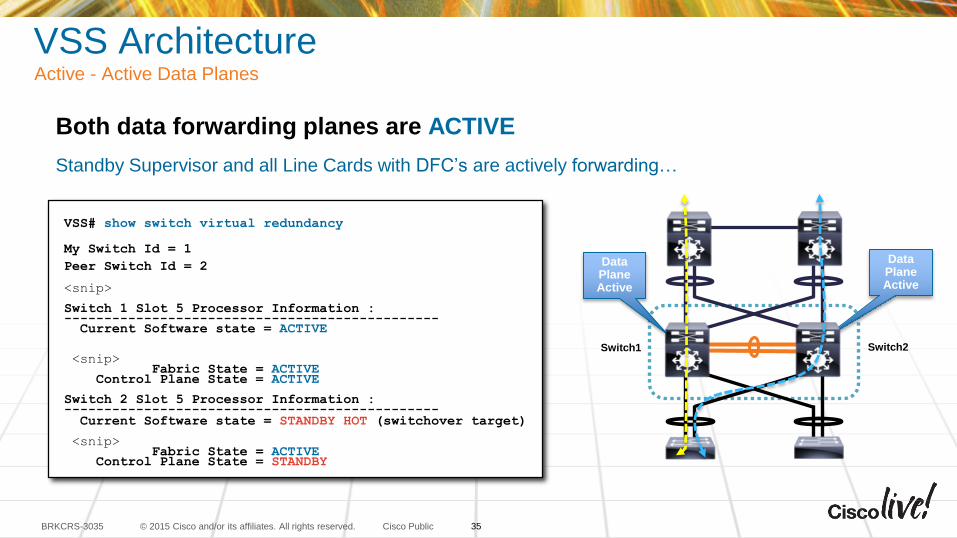
VSS ArchitectureActive - Active Data Planes
Both data forwarding planes are ACTIVE
Standby Supervisor and all Line Cards with DFC’s are actively forwarding…
VSS# show switch virtual redundancy
My Switch Id = 1
Peer Switch Id = 2
<snip>
Switch 1 Slot 5 Processor Information :-----------------------------------------------
Current Software state = ACTIVE
<snip>Fabric State = ACTIVE
Control Plane State = ACTIVE
Switch 2 Slot 5 Processor Information :-----------------------------------------------
Current Software state = STANDBY HOT (switchover target)
<snip>Fabric State = ACTIVE
Control Plane State = STANDBY
Data PlaneActive
Data Plane Active
Switch1 Switch2
35
© 2015 Cisco and/or its affiliates. All rights reserved.BRKCRS-3035 Cisco Public
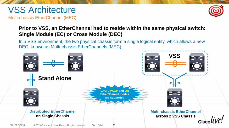
VSS ArchitectureMulti-chassis EtherChannel (MEC)
Prior to VSS, an EtherChannel had to reside within the same physical switch:
Single Module (EC) or Cross Module (DEC)
In a VSS environment, the two physical chassis form a single logical entity, which allows a new
DEC, known as Multi-chassis EtherChannels (MEC)
Distributed EtherChannel
on Single ChassisMulti-chassis EtherChannel
across 2 VSS Chassis
VSS
Stand Alone
LACP, PAGP and ON
EtherChannel modes
are supported
36
© 2015 Cisco and/or its affiliates. All rights reserved.BRKCRS-3035 Cisco Public
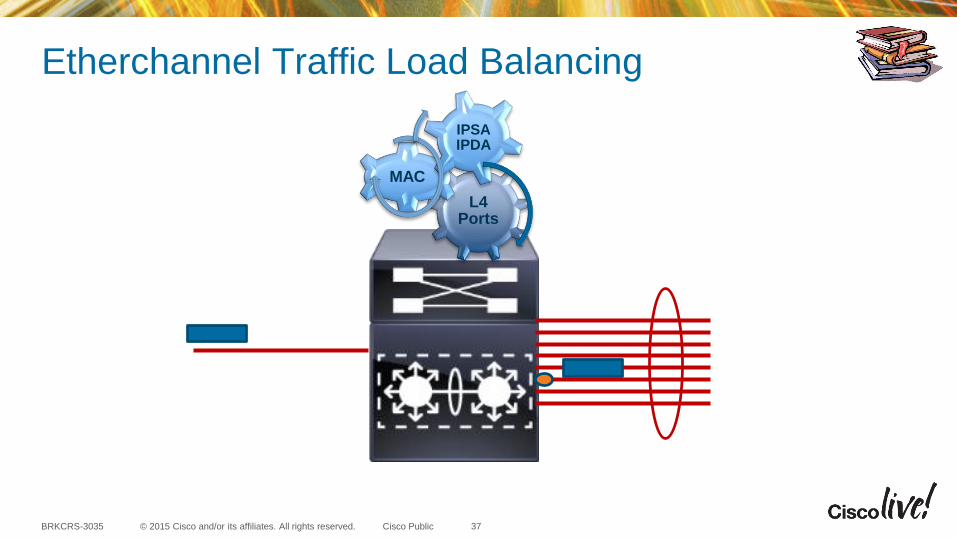
Etherchannel Traffic Load Balancing
L4 Ports
MAC
IPSA IPDA
37
© 2015 Cisco and/or its affiliates. All rights reserved.BRKCRS-3035 Cisco Public
VSS
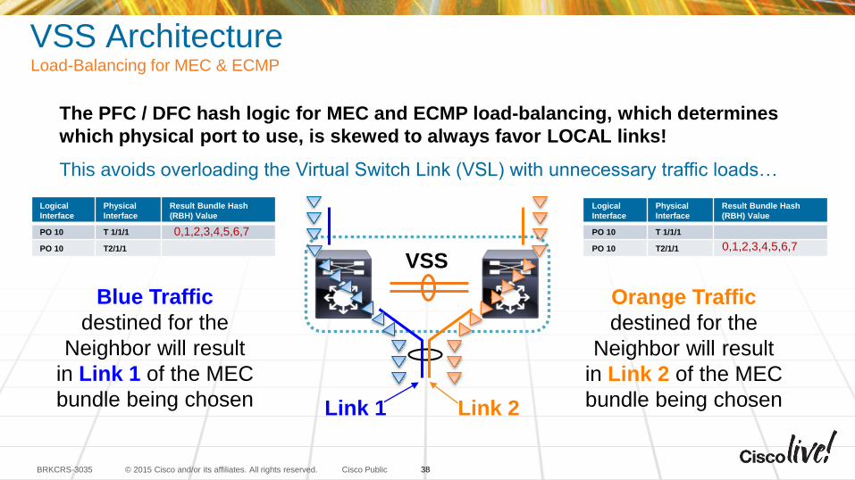
VSS ArchitectureLoad-Balancing for MEC & ECMP
The PFC / DFC hash logic for MEC and ECMP load-balancing, which determines
which physical port to use, is skewed to always favor LOCAL links!
This avoids overloading the Virtual Switch Link (VSL) with unnecessary traffic loads…
Link 1 Link 2
Blue Traffic
destined for the
Neighbor will result
in Link 1 of the MEC
bundle being chosen
Orange Traffic
destined for the
Neighbor will result
in Link 2 of the MEC
bundle being chosen
38
Logical
Interface
Physical
Interface
Result Bundle Hash
(RBH) Value
PO 10 T 1/1/1
PO 10 T2/1/1
Logical
Interface
Physical
Interface
Result Bundle Hash
(RBH) Value
PO 10 T 1/1/1
PO 10 T2/1/1
0,1,2,3,4,5,6,7
0,1,2,3,4,5,6,7
© 2015 Cisco and/or its affiliates. All rights reserved.BRKCRS-3035 Cisco Public
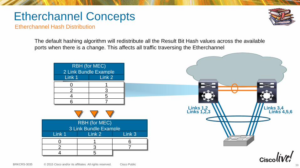
Etherchannel ConceptsEtherchannel Hash Distribution
The default hashing algorithm will redistribute all the Result Bit Hash values across the available
ports when there is a change. This affects all traffic traversing the Etherchannel
RBH (for MEC)
2 Link Bundle ExampleLink 1 Link 2
0 12 34 56 7
RBH (for MEC)
3 Link Bundle Example
0 12 34 5
67
Link 1 Link 2 Link 3
Links 1,2 Links 3,4Links 1,2,3 Links 4,5,6
39
© 2015 Cisco and/or its affiliates. All rights reserved.BRKCRS-3035 Cisco Public
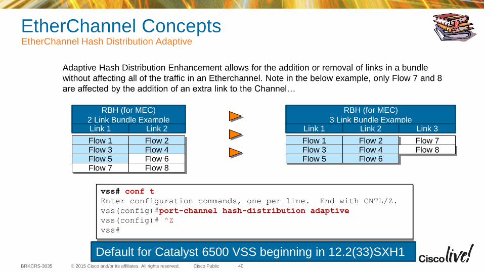
EtherChannel ConceptsEtherChannel Hash Distribution Adaptive
40
Adaptive Hash Distribution Enhancement allows for the addition or removal of links in a bundle
without affecting all of the traffic in an Etherchannel. Note in the below example, only Flow 7 and 8
are affected by the addition of an extra link to the Channel…
RBH (for MEC)
2 Link Bundle Example
RBH (for MEC)
3 Link Bundle Example
Flow 1 Flow 2Flow 3 Flow 4Flow 5 Flow 6
Flow 7Flow 8
Link 1 Link 2
Flow 1 Flow 2Flow 3 Flow 4Flow 5 Flow 6Flow 7 Flow 8
Link 1 Link 2 Link 3
vss# conf t
Enter configuration commands, one per line. End with CNTL/Z.
vss(config)#port-channel hash-distribution adaptive
vss(config)# ^Z
vss#
Default for Catalyst 6500 VSS beginning in 12.2(33)SXH1
© 2015 Cisco and/or its affiliates. All rights reserved.BRKCRS-3035 Cisco Public
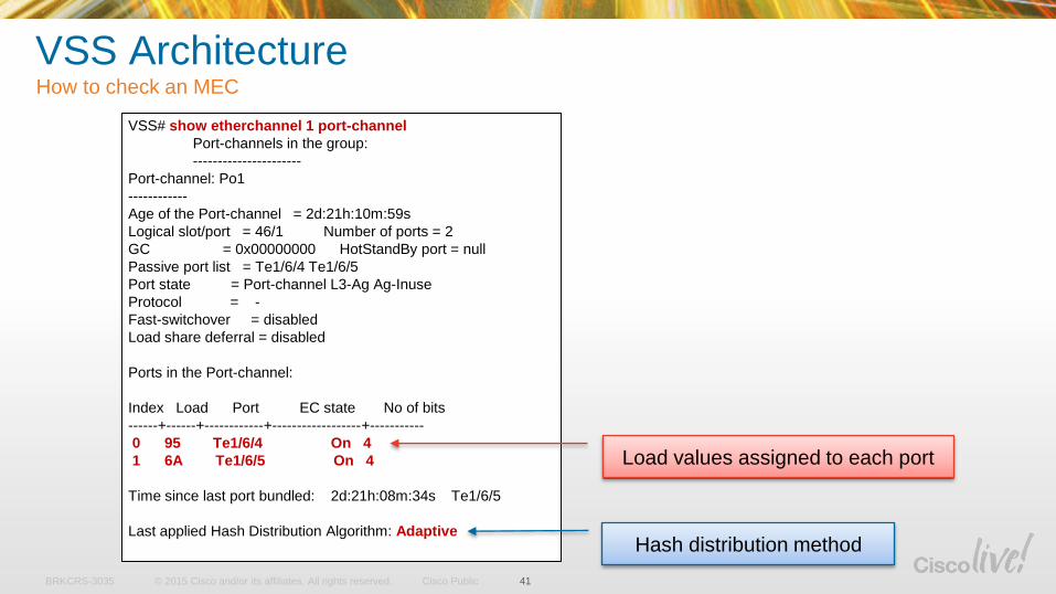
VSS# show etherchannel 1 port-channel
Port-channels in the group:
----------------------
Port-channel: Po1
------------
Age of the Port-channel = 2d:21h:10m:59s
Logical slot/port = 46/1 Number of ports = 2
GC = 0x00000000 HotStandBy port = null
Passive port list = Te1/6/4 Te1/6/5
Port state = Port-channel L3-Ag Ag-Inuse
Protocol = -
Fast-switchover = disabled
Load share deferral = disabled
Ports in the Port-channel:
Index Load Port EC state No of bits
------+------+------------+------------------+-----------
0 95 Te1/6/4 On 4
1 6A Te1/6/5 On 4
Time since last port bundled: 2d:21h:08m:34s Te1/6/5
Last applied Hash Distribution Algorithm: Adaptive
VSS ArchitectureHow to check an MEC
41
Load values assigned to each port
Hash distribution method
© 2015 Cisco and/or its affiliates. All rights reserved.BRKCRS-3035 Cisco Public
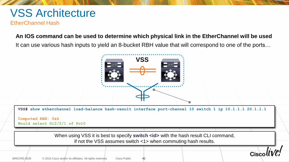
VSS ArchitectureEtherChannel Hash
VSS# show etherchannel load-balance hash-result interface port-channel 10 switch 1 ip 10.1.1.1 20.1.1.1
Computed RBH: 0x4
Would select Gi2/2/1 of Po10
An IOS command can be used to determine which physical link in the EtherChannel will be used
It can use various hash inputs to yield an 8-bucket RBH value that will correspond to one of the ports…
When using VSS it is best to specify switch <id> with the hash result CLI command,
if not the VSS assumes switch <1> when commuting hash results.
VSS
42
© 2015 Cisco and/or its affiliates. All rights reserved.BRKCRS-3035 Cisco Public
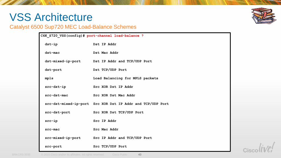
VSS ArchitectureCatalyst 6500 Sup720 MEC Load-Balance Schemes
43
C6K_S720_VSS(config)# port-channel load-balance ?
dst-ip Dst IP Addr
dst-mac Dst Mac Addr
dst-mixed-ip-port Dst IP Addr and TCP/UDP Port
dst-port Dst TCP/UDP Port
mpls Load Balancing for MPLS packets
src-dst-ip Src XOR Dst IP Addr
src-dst-mac Src XOR Dst Mac Addr
src-dst-mixed-ip-port Src XOR Dst IP Addr and TCP/UDP Port
src-dst-port Src XOR Dst TCP/UDP Port
src-ip Src IP Addr
src-mac Src Mac Addr
src-mixed-ip-port Src IP Addr and TCP/UDP Port
src-port Src TCP/UDP Port
© 2015 Cisco and/or its affiliates. All rights reserved.BRKCRS-3035 Cisco Public
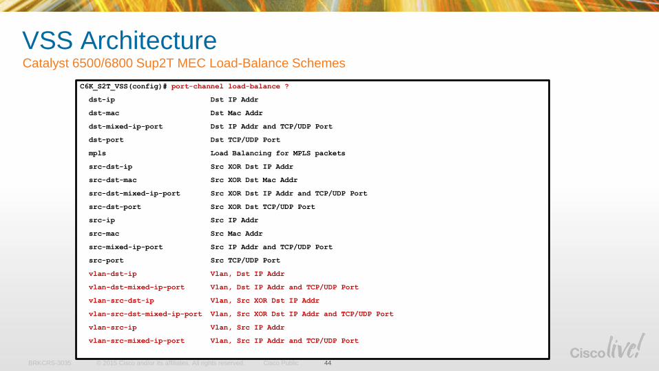
VSS ArchitectureCatalyst 6500/6800 Sup2T MEC Load-Balance Schemes
44
C6K_S2T_VSS(config)# port-channel load-balance ?
dst-ip Dst IP Addr
dst-mac Dst Mac Addr
dst-mixed-ip-port Dst IP Addr and TCP/UDP Port
dst-port Dst TCP/UDP Port
mpls Load Balancing for MPLS packets
src-dst-ip Src XOR Dst IP Addr
src-dst-mac Src XOR Dst Mac Addr
src-dst-mixed-ip-port Src XOR Dst IP Addr and TCP/UDP Port
src-dst-port Src XOR Dst TCP/UDP Port
src-ip Src IP Addr
src-mac Src Mac Addr
src-mixed-ip-port Src IP Addr and TCP/UDP Port
src-port Src TCP/UDP Port
vlan-dst-ip Vlan, Dst IP Addr
vlan-dst-mixed-ip-port Vlan, Dst IP Addr and TCP/UDP Port
vlan-src-dst-ip Vlan, Src XOR Dst IP Addr
vlan-src-dst-mixed-ip-port Vlan, Src XOR Dst IP Addr and TCP/UDP Port
vlan-src-ip Vlan, Src IP Addr
vlan-src-mixed-ip-port Vlan, Src IP Addr and TCP/UDP Port
© 2015 Cisco and/or its affiliates. All rights reserved.BRKCRS-3035 Cisco Public
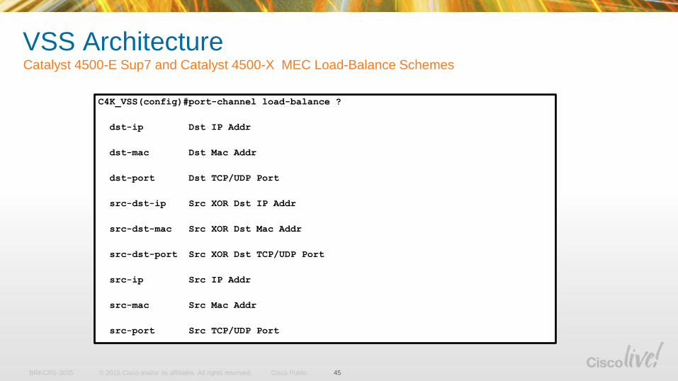
VSS ArchitectureCatalyst 4500-E Sup7 and Catalyst 4500-X MEC Load-Balance Schemes
45
C4K_VSS(config)#port-channel load-balance ?
dst-ip Dst IP Addr
dst-mac Dst Mac Addr
dst-port Dst TCP/UDP Port
src-dst-ip Src XOR Dst IP Addr
src-dst-mac Src XOR Dst Mac Addr
src-dst-port Src XOR Dst TCP/UDP Port
src-ip Src IP Addr
src-mac Src Mac Addr
src-port Src TCP/UDP Port
© 2015 Cisco and/or its affiliates. All rights reserved.BRKCRS-3035 Cisco Public
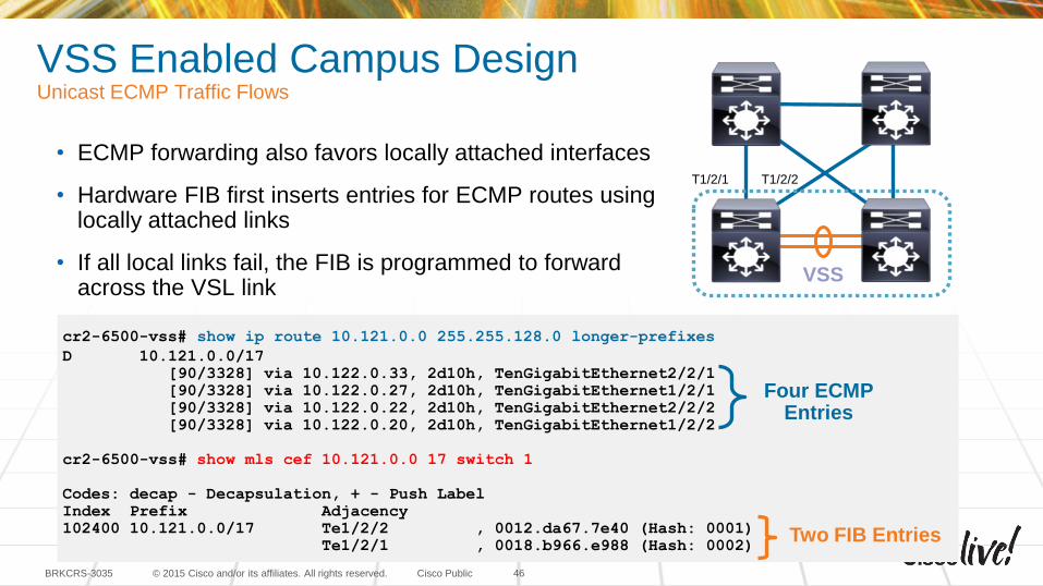
VSS Enabled Campus DesignUnicast ECMP Traffic Flows
46
• ECMP forwarding also favors locally attached interfaces
• Hardware FIB first inserts entries for ECMP routes using locally attached links
• If all local links fail, the FIB is programmed to forward across the VSL link
cr2-6500-vss# show ip route 10.121.0.0 255.255.128.0 longer-prefixes
D 10.121.0.0/17
[90/3328] via 10.122.0.33, 2d10h, TenGigabitEthernet2/2/1
[90/3328] via 10.122.0.27, 2d10h, TenGigabitEthernet1/2/1
[90/3328] via 10.122.0.22, 2d10h, TenGigabitEthernet2/2/2
[90/3328] via 10.122.0.20, 2d10h, TenGigabitEthernet1/2/2
cr2-6500-vss# show mls cef 10.121.0.0 17 switch 1
Codes: decap - Decapsulation, + - Push Label
Index Prefix Adjacency
102400 10.121.0.0/17 Te1/2/2 , 0012.da67.7e40 (Hash: 0001)
Te1/2/1 , 0018.b966.e988 (Hash: 0002)
Four ECMP Entries
Two FIB Entries
T1/2/1 T1/2/2
VSS
VSS Hardware and Software Requirements
© 2015 Cisco and/or its affiliates. All rights reserved.BRKCRS-3035 Cisco Public
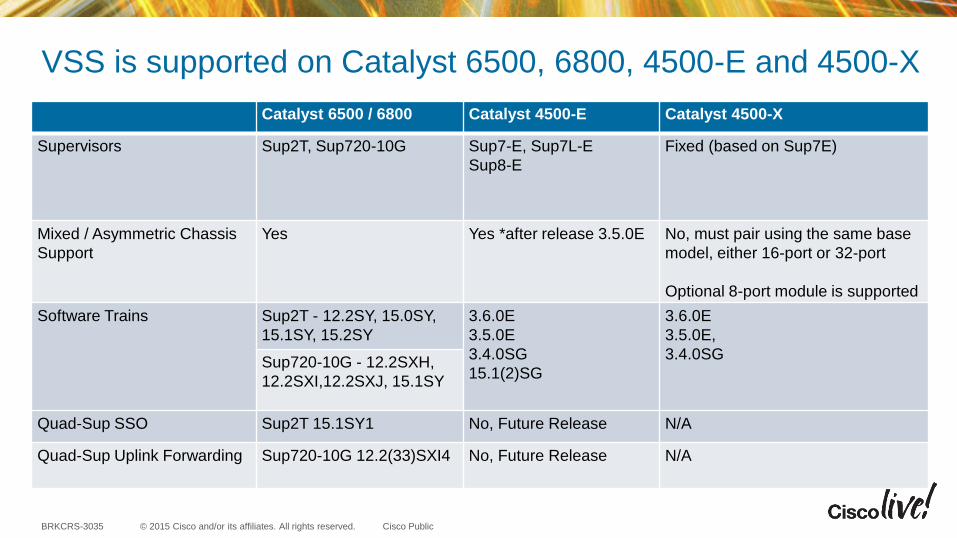
VSS is supported on Catalyst 6500, 6800, 4500-E and 4500-X
Catalyst 6500 / 6800 Catalyst 4500-E Catalyst 4500-X
Supervisors Sup2T, Sup720-10G Sup7-E, Sup7L-E
Sup8-E
Fixed (based on Sup7E)
Mixed / Asymmetric Chassis
Support
Yes Yes *after release 3.5.0E No, must pair using the same base
model, either 16-port or 32-port
Optional 8-port module is supported
Software Trains Sup2T - 12.2SY, 15.0SY,
15.1SY, 15.2SY
3.6.0E
3.5.0E
3.4.0SG
15.1(2)SG
3.6.0E
3.5.0E,
3.4.0SGSup720-10G - 12.2SXH,
12.2SXI,12.2SXJ, 15.1SY
Quad-Sup SSO Sup2T 15.1SY1 No, Future Release N/A
Quad-Sup Uplink Forwarding Sup720-10G 12.2(33)SXI4 No, Future Release N/A
© 2015 Cisco and/or its affiliates. All rights reserved.BRKCRS-3035 Cisco Public
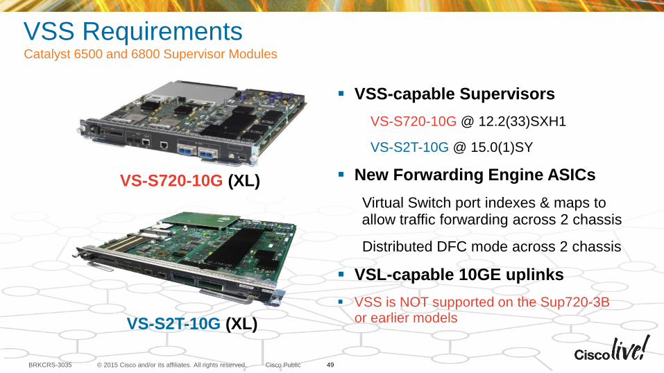
VSS RequirementsCatalyst 6500 and 6800 Supervisor Modules
VSS-capable Supervisors
VS-S720-10G @ 12.2(33)SXH1
VS-S2T-10G @ 15.0(1)SY
New Forwarding Engine ASICs
Virtual Switch port indexes & maps to allow traffic forwarding across 2 chassis
Distributed DFC mode across 2 chassis
VSL-capable 10GE uplinks
VSS is NOT supported on the Sup720-3B or earlier models
VS-S720-10G (XL)
VS-S2T-10G (XL)
49
© 2015 Cisco and/or its affiliates. All rights reserved.BRKCRS-3035 Cisco Public
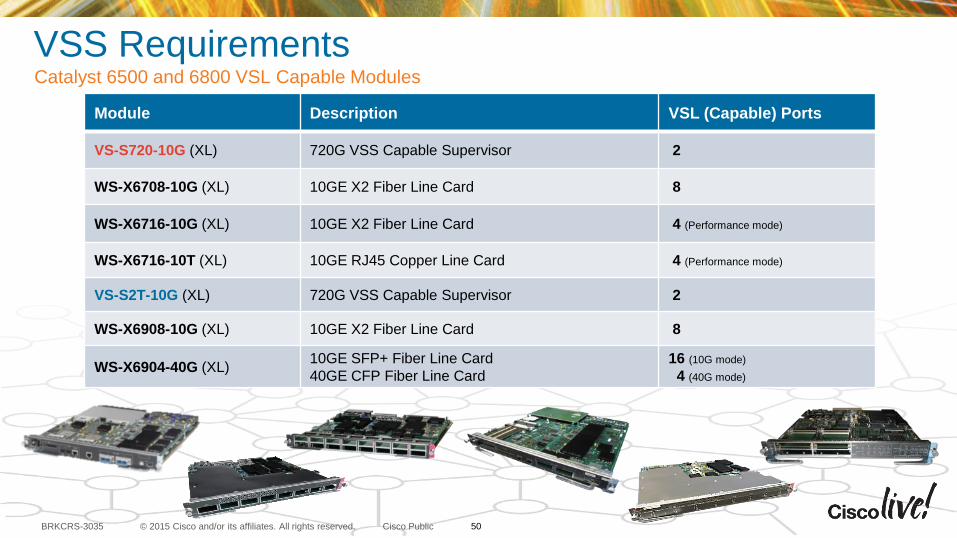
VSS RequirementsCatalyst 6500 and 6800 VSL Capable Modules
Module Description VSL (Capable) Ports
VS-S720-10G (XL) 720G VSS Capable Supervisor 2
WS-X6708-10G (XL) 10GE X2 Fiber Line Card 8
WS-X6716-10G (XL) 10GE X2 Fiber Line Card 4 (Performance mode)
WS-X6716-10T (XL) 10GE RJ45 Copper Line Card 4 (Performance mode)
VS-S2T-10G (XL) 720G VSS Capable Supervisor 2
WS-X6908-10G (XL) 10GE X2 Fiber Line Card 8
WS-X6904-40G (XL) 10GE SFP+ Fiber Line Card
40GE CFP Fiber Line Card
16 (10G mode)
4 (40G mode)
50
© 2015 Cisco and/or its affiliates. All rights reserved.BRKCRS-3035 Cisco Public
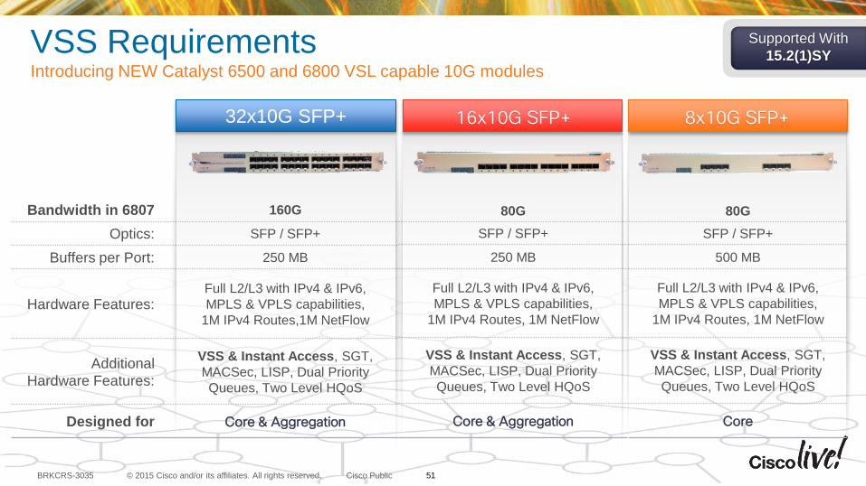
Bandwidth in 6807 160G
Optics: SFP / SFP+
Buffers per Port: 250 MB
Hardware Features:Full L2/L3 with IPv4 & IPv6,
MPLS & VPLS capabilities,
1M IPv4 Routes,1M NetFlow
Additional
Hardware Features:
VSS & Instant Access, SGT,
MACSec, LISP, Dual Priority
Queues, Two Level HQoS
Designed for Core & Aggregation
80G
SFP / SFP+
250 MB
Full L2/L3 with IPv4 & IPv6,
MPLS & VPLS capabilities,
1M IPv4 Routes, 1M NetFlow
VSS & Instant Access, SGT,
MACSec, LISP, Dual Priority
Queues, Two Level HQoS
Core & Aggregation
80G
SFP / SFP+
500 MB
Full L2/L3 with IPv4 & IPv6,
MPLS & VPLS capabilities,
1M IPv4 Routes, 1M NetFlow
VSS & Instant Access, SGT,
MACSec, LISP, Dual Priority
Queues, Two Level HQoS
Core
32x10G SFP+ 16x10G SFP+ 8x10G SFP+
Supported With
15.2(1)SYVSS RequirementsIntroducing NEW Catalyst 6500 and 6800 VSL capable 10G modules
51
© 2015 Cisco and/or its affiliates. All rights reserved.BRKCRS-3035 Cisco Public
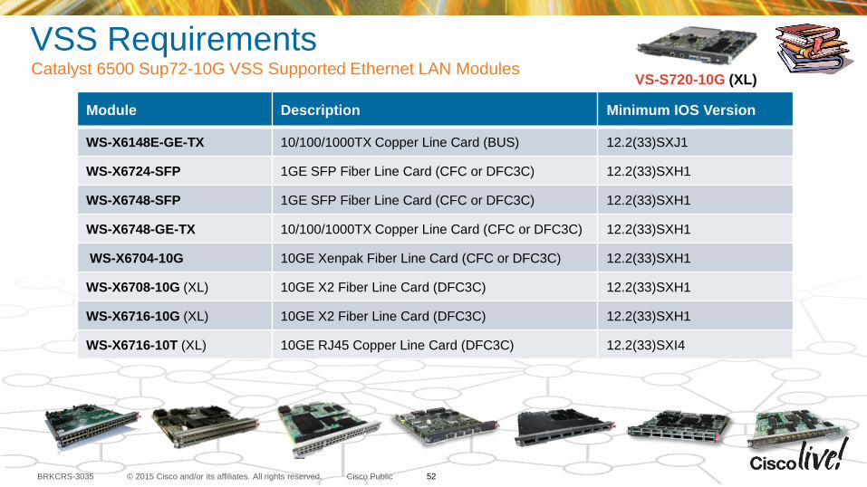
VSS RequirementsCatalyst 6500 Sup72-10G VSS Supported Ethernet LAN Modules
Module Description Minimum IOS Version
WS-X6148E-GE-TX 10/100/1000TX Copper Line Card (BUS) 12.2(33)SXJ1
WS-X6724-SFP 1GE SFP Fiber Line Card (CFC or DFC3C) 12.2(33)SXH1
WS-X6748-SFP 1GE SFP Fiber Line Card (CFC or DFC3C) 12.2(33)SXH1
WS-X6748-GE-TX 10/100/1000TX Copper Line Card (CFC or DFC3C) 12.2(33)SXH1
WS-X6704-10G 10GE Xenpak Fiber Line Card (CFC or DFC3C) 12.2(33)SXH1
WS-X6708-10G (XL) 10GE X2 Fiber Line Card (DFC3C) 12.2(33)SXH1
WS-X6716-10G (XL) 10GE X2 Fiber Line Card (DFC3C) 12.2(33)SXH1
WS-X6716-10T (XL) 10GE RJ45 Copper Line Card (DFC3C) 12.2(33)SXI4
VS-S720-10G (XL)
52
© 2015 Cisco and/or its affiliates. All rights reserved.BRKCRS-3035 Cisco Public
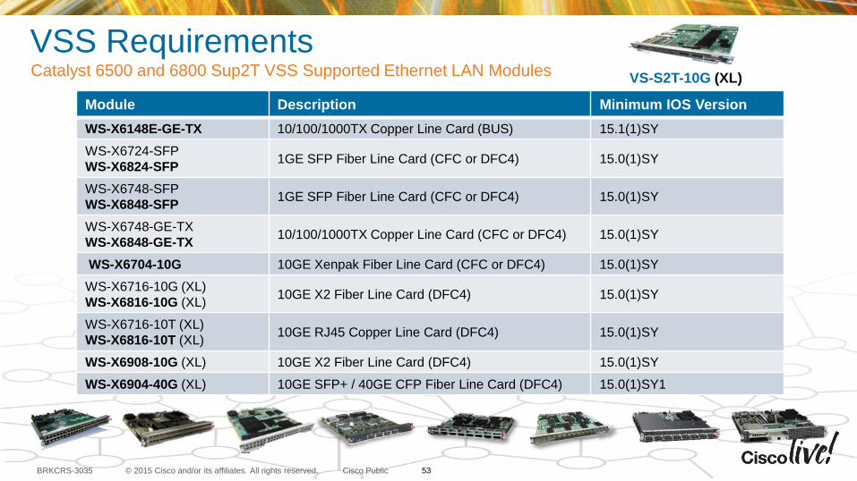
VSS RequirementsCatalyst 6500 and 6800 Sup2T VSS Supported Ethernet LAN Modules
Module Description Minimum IOS Version
WS-X6148E-GE-TX 10/100/1000TX Copper Line Card (BUS) 15.1(1)SY
WS-X6724-SFP
WS-X6824-SFP1GE SFP Fiber Line Card (CFC or DFC4) 15.0(1)SY
WS-X6748-SFP
WS-X6848-SFP1GE SFP Fiber Line Card (CFC or DFC4) 15.0(1)SY
WS-X6748-GE-TX
WS-X6848-GE-TX10/100/1000TX Copper Line Card (CFC or DFC4) 15.0(1)SY
WS-X6704-10G 10GE Xenpak Fiber Line Card (CFC or DFC4) 15.0(1)SY
WS-X6716-10G (XL)
WS-X6816-10G (XL) 10GE X2 Fiber Line Card (DFC4) 15.0(1)SY
WS-X6716-10T (XL)
WS-X6816-10T (XL) 10GE RJ45 Copper Line Card (DFC4) 15.0(1)SY
WS-X6908-10G (XL) 10GE X2 Fiber Line Card (DFC4) 15.0(1)SY
WS-X6904-40G (XL) 10GE SFP+ / 40GE CFP Fiber Line Card (DFC4) 15.0(1)SY1
VS-S2T-10G (XL)
53
© 2015 Cisco and/or its affiliates. All rights reserved.BRKCRS-3035 Cisco Public
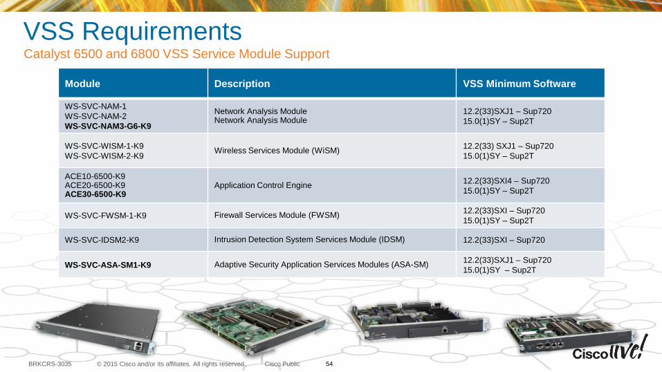
VSS RequirementsCatalyst 6500 and 6800 VSS Service Module Support
Module Description VSS Minimum Software
WS-SVC-NAM-1
WS-SVC-NAM-2
WS-SVC-NAM3-G6-K9
Network Analysis ModuleNetwork Analysis Module
12.2(33)SXJ1 – Sup720
15.0(1)SY – Sup2T
WS-SVC-WISM-1-K9
WS-SVC-WISM-2-K9Wireless Services Module (WiSM)
12.2(33) SXJ1 – Sup720
15.0(1)SY – Sup2T
ACE10-6500-K9ACE20-6500-K9ACE30-6500-K9
Application Control Engine12.2(33)SXI4 – Sup720
15.0(1)SY – Sup2T
WS-SVC-FWSM-1-K9 Firewall Services Module (FWSM)12.2(33)SXI – Sup720
15.0(1)SY – Sup2T
WS-SVC-IDSM2-K9 Intrusion Detection System Services Module (IDSM) 12.2(33)SXI – Sup720
WS-SVC-ASA-SM1-K9 Adaptive Security Application Services Modules (ASA-SM)12.2(33)SXJ1 – Sup720
15.0(1)SY – Sup2T
54
© 2015 Cisco and/or its affiliates. All rights reserved.BRKCRS-3035 Cisco Public
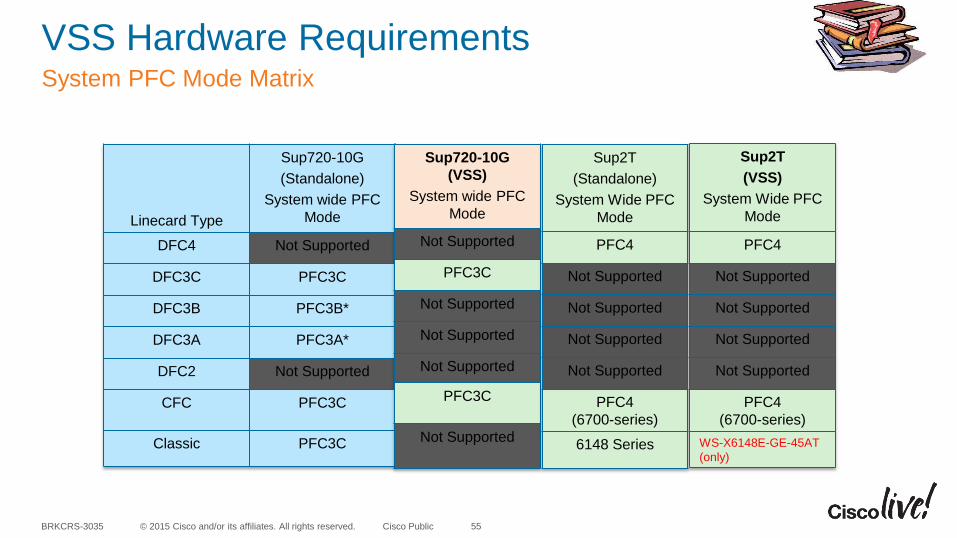
VSS Hardware RequirementsSystem PFC Mode Matrix
55
Linecard Type
Sup720-10G
(Standalone)
System wide PFC
Mode
DFC4 Not Supported
DFC3C PFC3C
DFC3B PFC3B*
DFC3A PFC3A*
DFC2 Not Supported
CFC PFC3C
Classic PFC3C
Sup720-10G
(VSS)
System wide PFC
Mode
Not Supported
PFC3C
Not Supported
Not Supported
Not Supported
PFC3C
Not Supported
Sup2T
(Standalone)
System Wide PFC
Mode
PFC4
Not Supported
Not Supported
Not Supported
Not Supported
PFC4
(6700-series)
6148 Series
Sup2T
(VSS)
System Wide PFC
Mode
PFC4
Not Supported
Not Supported
Not Supported
Not Supported
PFC4
(6700-series)
WS-X6148E-GE-45AT
(only)
© 2015 Cisco and/or its affiliates. All rights reserved.BRKCRS-3035 Cisco Public
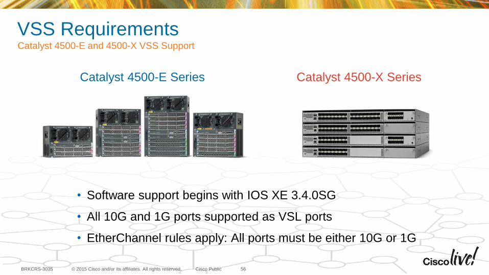
VSS RequirementsCatalyst 4500-E and 4500-X VSS Support
56
• Software support begins with IOS XE 3.4.0SG
• All 10G and 1G ports supported as VSL ports
• EtherChannel rules apply: All ports must be either 10G or 1G
Catalyst 4500-E Series Catalyst 4500-X Series
© 2015 Cisco and/or its affiliates. All rights reserved.BRKCRS-3035 Cisco Public
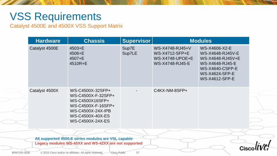
VSS RequirementsCatalyst 4500E and 4500X VSS Support Matrix
57
Hardware Chassis Supervisor Modules
Catalyst 4500E 4503+E
4506+E
4507+E
4510R+E
Sup7E
Sup7LE
WS-X4748-RJ45+V
WS-X4712-SFP+E
WS-X4748-UPOE+E
WS-X4748-RJ45-E
WS-X4606-X2-E
WS-X4648-RJ45V-E
WS-X4648-RJ45V+E
WS-X4648-RJ45-E
WS-X4640-CSFP-E
WS-X4624-SFP-E
WS-X4612-SFP-E
Catalyst 4500X WS-C4500X-32SFP+
WS-C4500X-F-32SFP+
WS-C4500X16SFP+
WS-C4500X-F-16SFP+
WS-C4500X-24X-IPB
WS-C4500X-40X-ES
WS-C4500X-24X-ES
- C4KX-NM-8SFP+
All supported 4500-E series modules are VSL capable
Legacy modules WS-45XX and WS-42XX are not supported
© 2015 Cisco and/or its affiliates. All rights reserved.BRKCRS-3035 Cisco Public
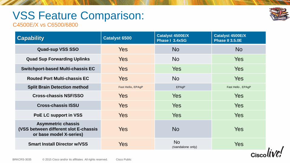
VSS Feature Comparison: C4500E/X vs C6500/6800
Capability Catalyst 6500Catalyst 4500E/X
Phase I 3.4xSG
Catalyst 4500E/X
Phase II 3.5.0E
Quad-sup VSS SSO Yes No No
Quad Sup Forwarding Uplinks Yes No Yes
Switchport-based Multi-chassis EC Yes Yes Yes
Routed Port Multi-chassis EC Yes No Yes
Split Brain Detection method Fast Hello, EPAgP EPAgP Fast Hello , EPAgP
Cross-chassis NSF/SSO Yes Yes Yes
Cross-chassis ISSU Yes Yes Yes
PoE LC support in VSS Yes Yes Yes
Asymmetric chassis
(VSS between different slot E-chassis
or base model X-series)Yes No Yes
Smart Install Director w/VSS Yes No(Standalone only)
Yes
© 2015 Cisco and/or its affiliates. All rights reserved.BRKCRS-3035 Cisco Public
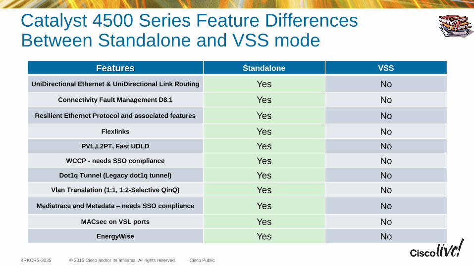
Catalyst 4500 Series Feature Differences Between Standalone and VSS mode
Features Standalone VSS
UniDirectional Ethernet & UniDirectional Link Routing Yes No
Connectivity Fault Management D8.1 Yes No
Resilient Ethernet Protocol and associated features Yes No
Flexlinks Yes No
PVL,L2PT, Fast UDLD Yes No
WCCP - needs SSO compliance Yes No
Dot1q Tunnel (Legacy dot1q tunnel) Yes No
Vlan Translation (1:1, 1:2-Selective QinQ) Yes No
Mediatrace and Metadata – needs SSO compliance Yes No
MACsec on VSL ports Yes No
EnergyWise Yes No
© 2015 Cisco and/or its affiliates. All rights reserved.BRKCRS-3035 Cisco Public
VSS RequirementsAlways Verify Supported Hardware with Software Release Notes
• Catalyst 6800/6500/4500 modular platforms are designed for very long product lifecycles
• Investment Protection is a key design criteria
• Overtime older hardware support is not carried forward with the newest software releases in order to minimize complexity, optimize performance, increase feature velocity or all of the above
• New features are sometimes phased in with only the most relevant hardware support in the initial release
60
Before every deployment always read the Release Notes for the planned software release and check the Supported Hardware section to verify all components are supported.
High Availability
© 2015 Cisco and/or its affiliates. All rights reserved.BRKCRS-3035 Cisco Public
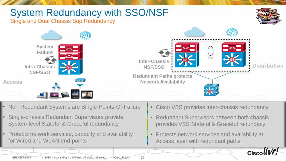
System Redundancy with SSO/NSFSingle and Dual Chassis Sup Redundancy
Network Outage
SiSi
Access
• Non-Redundant Systems are Single-Points-Of-Failure
• Single-chassis Redundant Supervisors provide
System-level Stateful & Graceful redundancy
• Protects network services, capacity and availability
for Wired and WLAN end-points
• Cisco VSS provides inter-chassis redundancy
• Redundant Supervisors between both chassis
provides VSS Stateful & Graceful redundacy
• Protects network services and availability at
Access layer with redundant paths
SiSi
SiSi SiSi
Distribution
VSL
Inter-Chassis
NSF/SSO
Redundant Paths protects
Network Availability
System
Failure
Intra-Chassis
NSF/SSO
62
© 2015 Cisco and/or its affiliates. All rights reserved.BRKCRS-3035 Cisco Public
Virtual Switch Hot StandbyVirtual Switch Active
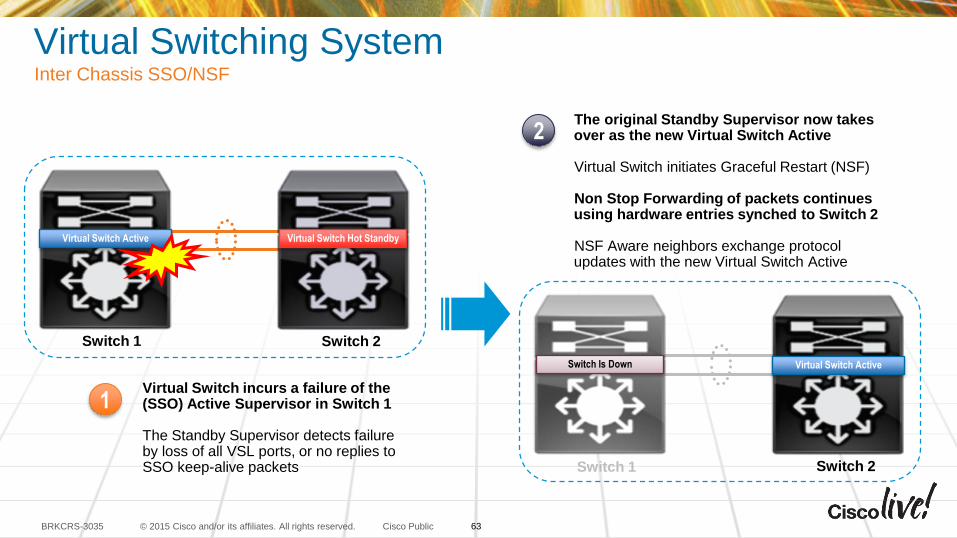
Virtual Switch incurs a failure of the (SSO) Active Supervisor in Switch 1
The Standby Supervisor detects failure by loss of all VSL ports, or no replies to SSO keep-alive packets
1
2The original Standby Supervisor now takes over as the new Virtual Switch Active
Virtual Switch initiates Graceful Restart (NSF)
Non Stop Forwarding of packets continues using hardware entries synched to Switch 2
NSF Aware neighbors exchange protocol updates with the new Virtual Switch Active
Switch 1 Switch 2
Virtual Switching SystemInter Chassis SSO/NSF
Switch 1 Switch 2
Switch Is Down Virtual Switch Active
63
© 2015 Cisco and/or its affiliates. All rights reserved.BRKCRS-3035 Cisco Public
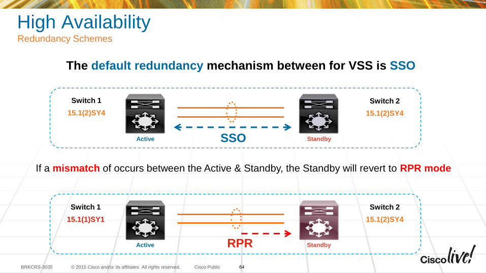
High AvailabilityRedundancy Schemes
The default redundancy mechanism between for VSS is SSO
If a mismatch of occurs between the Active & Standby, the Standby will revert to RPR mode
Switch 1
15.1(2)SY4
Switch 2
15.1(2)SY4
Switch 1
15.1(1)SY1
Switch 2
15.1(2)SY4
Active Standby
RPR
SSO
Active Standby
64
© 2015 Cisco and/or its affiliates. All rights reserved.BRKCRS-3035 Cisco Public
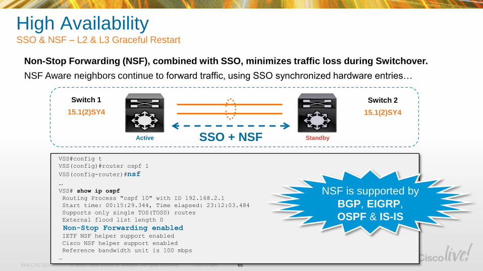
Non-Stop Forwarding (NSF), combined with SSO, minimizes traffic loss during Switchover.
NSF Aware neighbors continue to forward traffic, using SSO synchronized hardware entries…
VSS#config t
VSS(config)#router ospf 1
VSS(config-router)#nsf
…
VSS# show ip ospf
Routing Process "ospf 10" with ID 192.168.2.1
Start time: 00:15:29.344, Time elapsed: 23:12:03.484
Supports only single TOS(TOS0) routes
External flood list length 0
Non-Stop Forwarding enabledIETF NSF helper support enabled
Cisco NSF helper support enabled
Reference bandwidth unit is 100 mbps
…
High AvailabilitySSO & NSF – L2 & L3 Graceful Restart
Switch 1
15.1(2)SY4
Switch 2
15.1(2)SY4
Active StandbySSO + NSF
NSF is supported by
BGP, EIGRP,
OSPF & IS-IS
65

© 2015 Cisco and/or its affiliates. All rights reserved.BRKCRS-3035 Cisco Public
High AvailabilityFailure of MEC member – Upstream Traffic
No Change in Network Topology
Convergence time is determined by
Neighbor EtherChannel recalculation
Neighbor EtherChannel convergence is typically ~100-200ms
Only the flows on the Failed Link(s) are affected (recalculated)
1
3
2
66
© 2015 Cisco and/or its affiliates. All rights reserved.BRKCRS-3035 Cisco Public
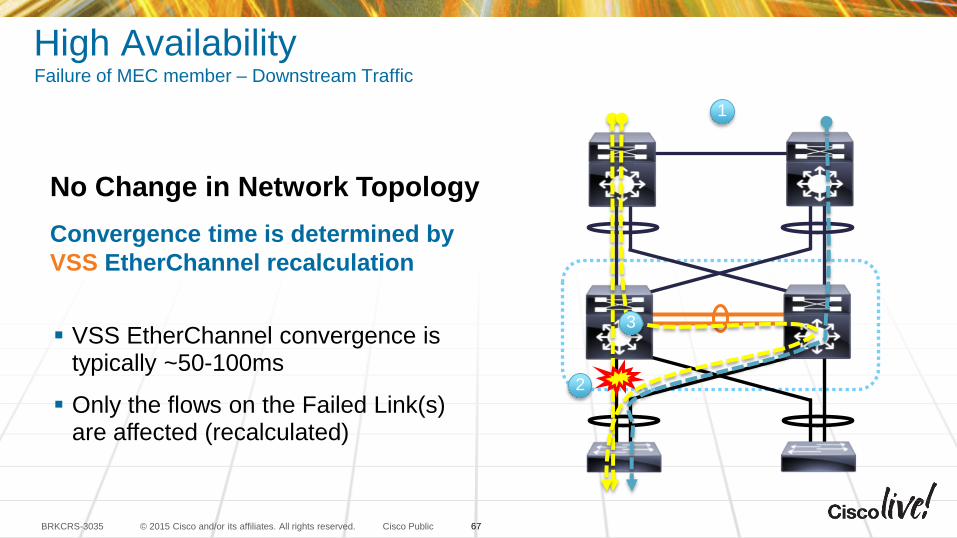
High AvailabilityFailure of MEC member – Downstream Traffic
No Change in Network Topology
Convergence time is determined by
VSS EtherChannel recalculation
VSS EtherChannel convergence is typically ~50-100ms
Only the flows on the Failed Link(s) are affected (recalculated)
1
2
3
67
Dual-Active Scenarios
© 2015 Cisco and/or its affiliates. All rights reserved.BRKCRS-3035 Cisco Public
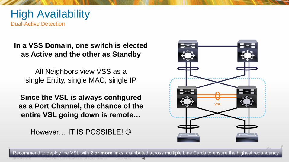
High AvailabilityDual-Active Detection
In a VSS Domain, one switch is elected
as Active and the other as Standby
All Neighbors view VSS as a
single Entity, single MAC, single IP
Since the VSL is always configured
as a Port Channel, the chance of the
entire VSL going down is remote…
However… IT IS POSSIBLE!
Recommend to deploy the VSL with 2 or more links, distributed across multiple Line Cards to ensure the highest redundancy
VSL
69
© 2015 Cisco and/or its affiliates. All rights reserved.BRKCRS-3035 Cisco Public
High AvailabilityDual-Active Detection
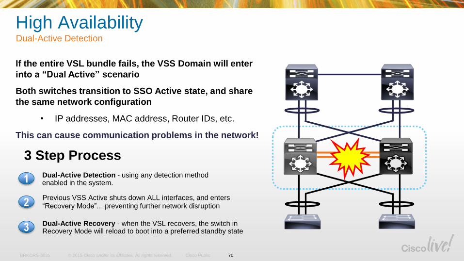
If the entire VSL bundle fails, the VSS Domain will enter
into a “Dual Active” scenario
Both switches transition to SSO Active state, and share
the same network configuration
• IP addresses, MAC address, Router IDs, etc.
This can cause communication problems in the network!
3 Step Process
Dual-Active Detection - using any detection method enabled in the system. 1
Previous VSS Active shuts down ALL interfaces, and enters “Recovery Mode”… preventing further network disruption2
Dual-Active Recovery - when the VSL recovers, the switch in Recovery Mode will reload to boot into a preferred standby state3
VSL
70
© 2015 Cisco and/or its affiliates. All rights reserved.BRKCRS-3035 Cisco Public
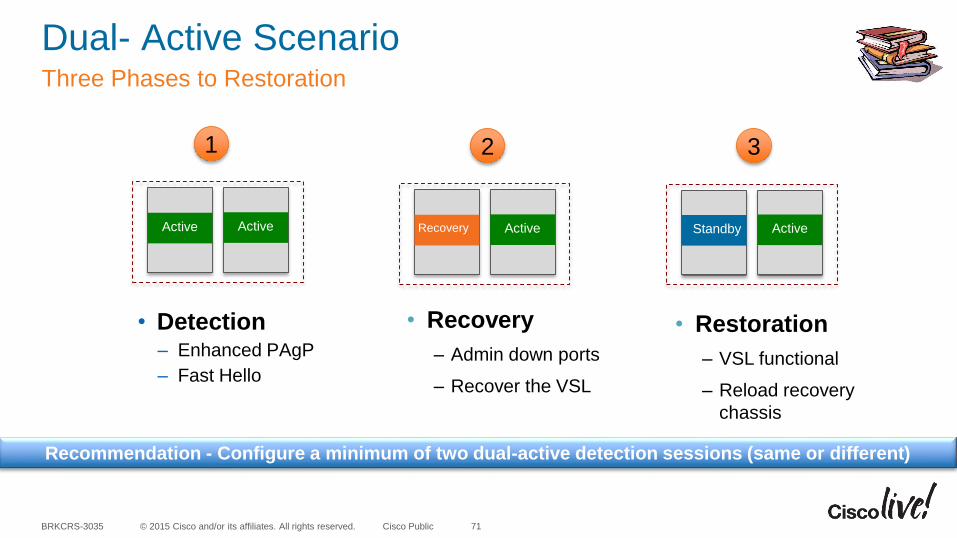
Dual- Active ScenarioThree Phases to Restoration
71
• Detection– Enhanced PAgP
– Fast Hello
1
Active Active Recovery Active
• Recovery
‒ Admin down ports
‒ Recover the VSL
2
Standby Active
• Restoration
‒ VSL functional
‒ Reload recovery
chassis
3
Recommendation - Configure a minimum of two dual-active detection sessions (same or different)
© 2015 Cisco and/or its affiliates. All rights reserved.BRKCRS-3035 Cisco Public
StandbyActive
Switch 1 Switch 2
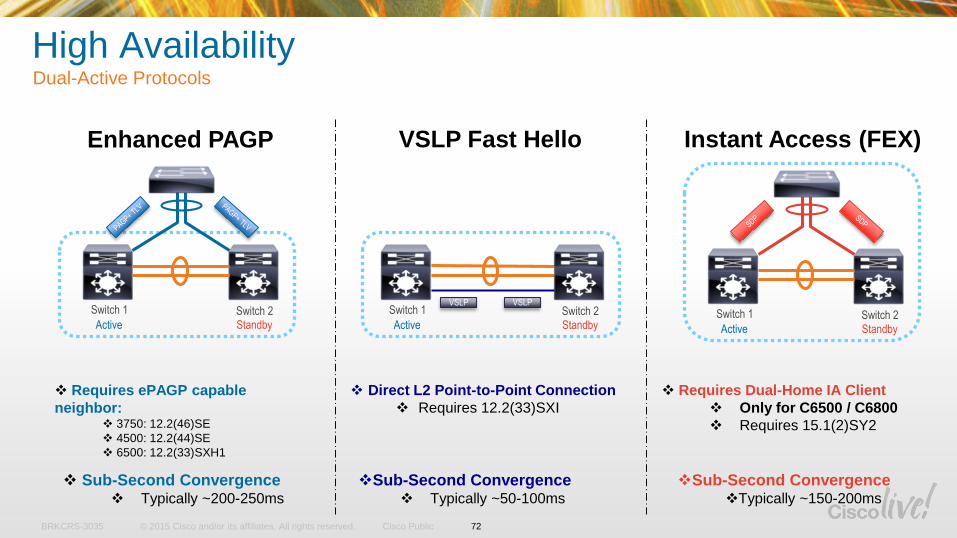
Enhanced PAGP Instant Access (FEX)
VSLP
VSLP Fast Hello
Requires ePAGP capable
neighbor: 3750: 12.2(46)SE
4500: 12.2(44)SE
6500: 12.2(33)SXH1
Direct L2 Point-to-Point Connection
Requires 12.2(33)SXI
Requires Dual-Home IA Client
Only for C6500 / C6800
Requires 15.1(2)SY2
Sub-Second Convergence Typically ~200-250ms
Sub-Second Convergence Typically ~50-100ms
Sub-Second ConvergenceTypically ~150-200ms
High AvailabilityDual-Active Protocols
StandbyActive
Switch 1 Switch 2VSLP
72
StandbyActive
Switch 1 Switch 2
© 2015 Cisco and/or its affiliates. All rights reserved.BRKCRS-3035 Cisco Public
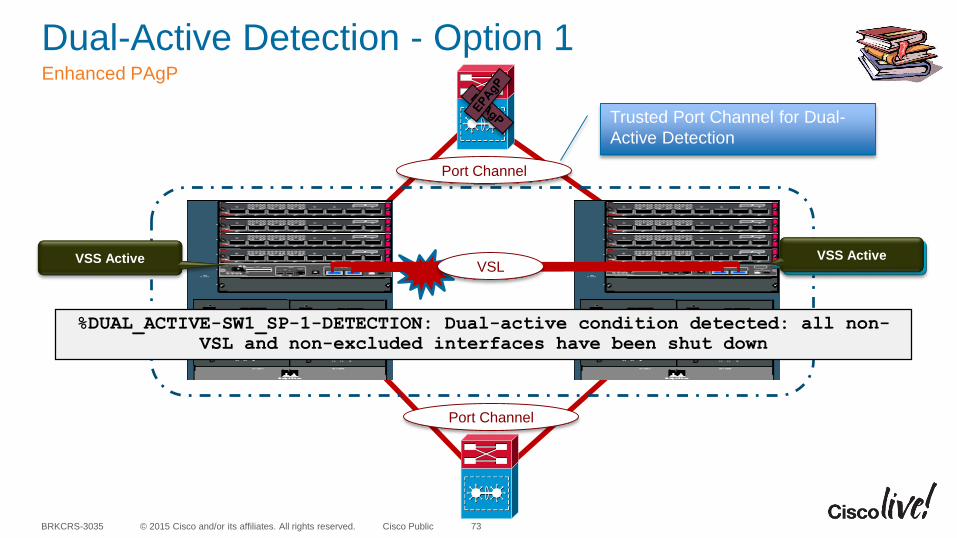
Dual-Active Detection - Option 1Enhanced PAgP
73
VSS Active VSS StandbyVSS Active
Port Channel
Port Channel
VSL
%DUAL_ACTIVE-SW1_SP-1-DETECTION: Dual-active condition detected: all non-
VSL and non-excluded interfaces have been shut down
Trusted Port Channel for Dual-
Active Detection
© 2015 Cisco and/or its affiliates. All rights reserved.BRKCRS-3035 Cisco Public
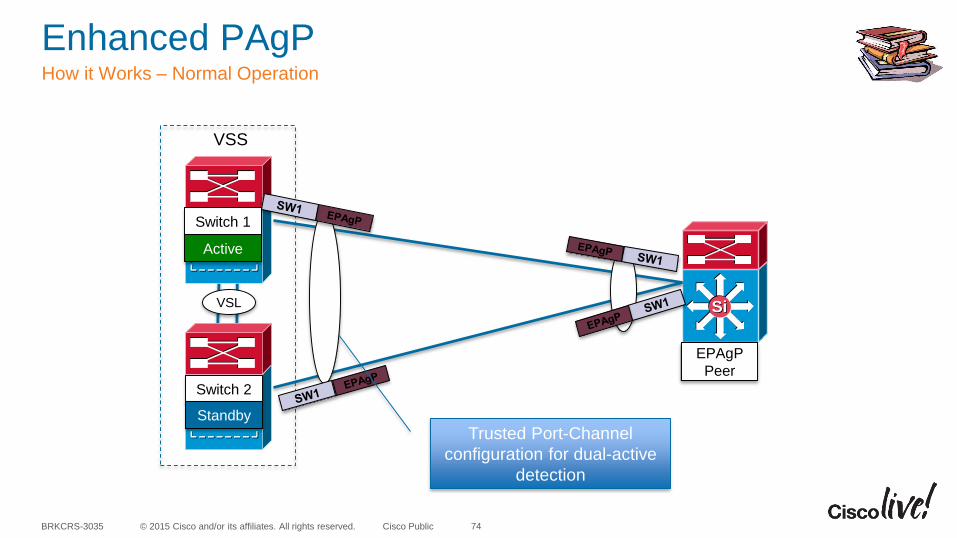
Enhanced PAgPHow it Works – Normal Operation
74
SiSi
Switch 2
Switch 1
Active
Standby
EPAgP
Peer
VSL
VSS
Trusted Port-Channel
configuration for dual-active
detection
© 2015 Cisco and/or its affiliates. All rights reserved.BRKCRS-3035 Cisco Public
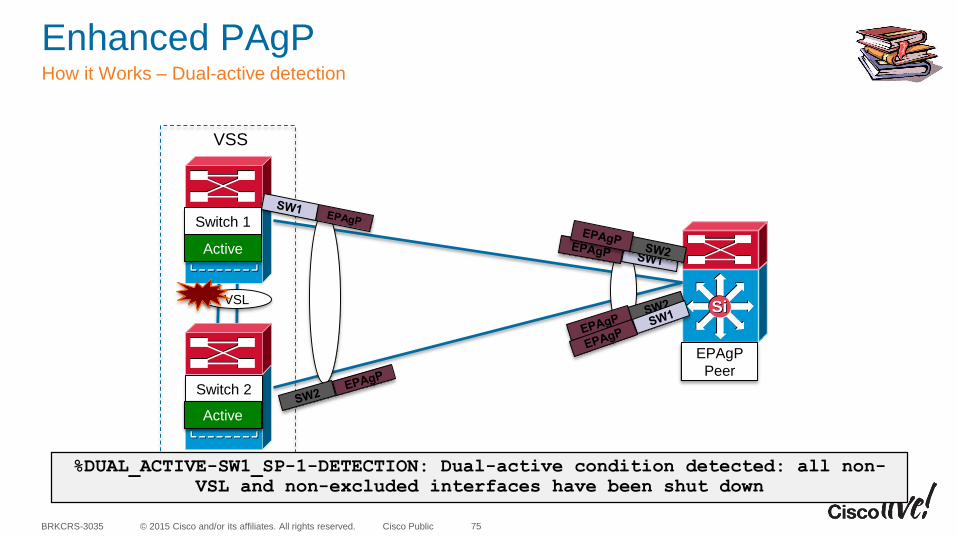
VSL
Enhanced PAgPHow it Works – Dual-active detection
75
SiSi
Switch 2
Switch 1
Active
Standby
EPAgP
Peer
VSS
Active
%DUAL_ACTIVE-SW1_SP-1-DETECTION: Dual-active condition detected: all non-
VSL and non-excluded interfaces have been shut down
© 2015 Cisco and/or its affiliates. All rights reserved.BRKCRS-3035 Cisco Public
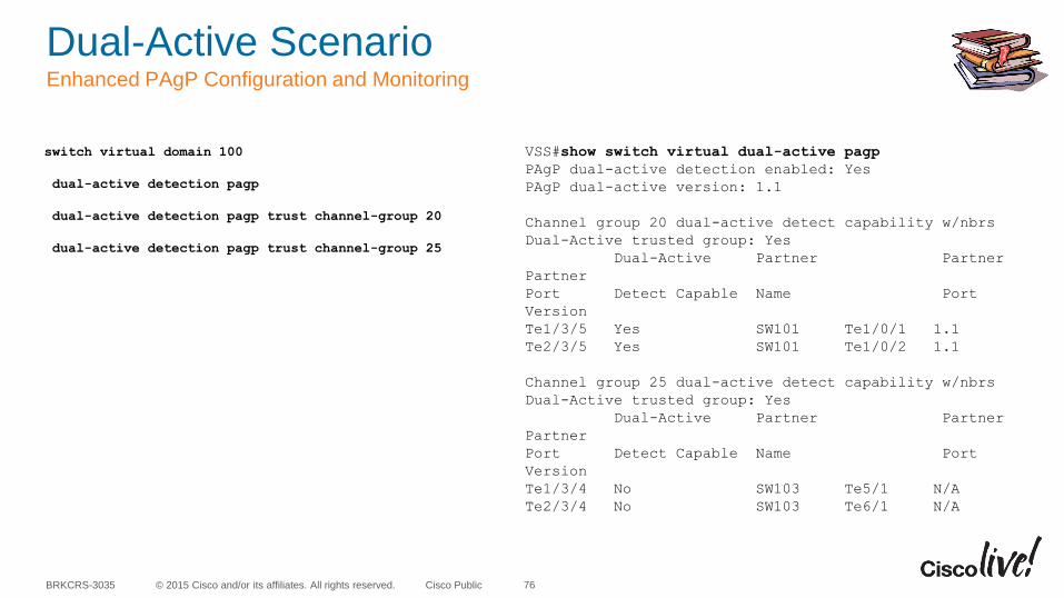
Dual-Active ScenarioEnhanced PAgP Configuration and Monitoring
76
switch virtual domain 100
dual-active detection pagp
dual-active detection pagp trust channel-group 20
dual-active detection pagp trust channel-group 25
VSS#show switch virtual dual-active pagp
PAgP dual-active detection enabled: Yes
PAgP dual-active version: 1.1
Channel group 20 dual-active detect capability w/nbrs
Dual-Active trusted group: Yes
Dual-Active Partner Partner
Partner
Port Detect Capable Name Port
Version
Te1/3/5 Yes SW101 Te1/0/1 1.1
Te2/3/5 Yes SW101 Te1/0/2 1.1
Channel group 25 dual-active detect capability w/nbrs
Dual-Active trusted group: Yes
Dual-Active Partner Partner
Partner
Port Detect Capable Name Port
Version
Te1/3/4 No SW103 Te5/1 N/A
Te2/3/4 No SW103 Te6/1 N/A
© 2015 Cisco and/or its affiliates. All rights reserved.BRKCRS-3035 Cisco Public
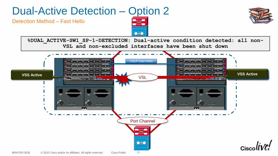
Dual-Active Detection – Option 2Detection Method – Fast Hello
77
VSS Active VSS StandbyVSS Active
Port Channel
Port Channel
VSL
%DUAL_ACTIVE-SW1_SP-1-DETECTION: Dual-active condition detected: all non-
VSL and non-excluded interfaces have been shut down
VSLP Fast Hello
© 2015 Cisco and/or its affiliates. All rights reserved.BRKCRS-3035 Cisco Public
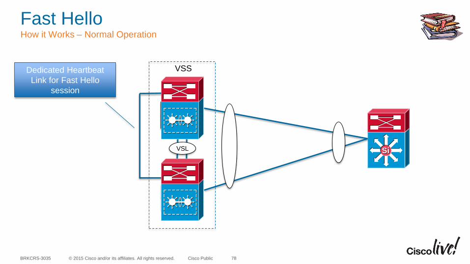
Fast Hello How it Works – Normal Operation
78
SiSi
Switch 2
Switch 1
Active
Standby
VSL
VSSDedicated Heartbeat
Link for Fast Hello
session
© 2015 Cisco and/or its affiliates. All rights reserved.BRKCRS-3035 Cisco Public
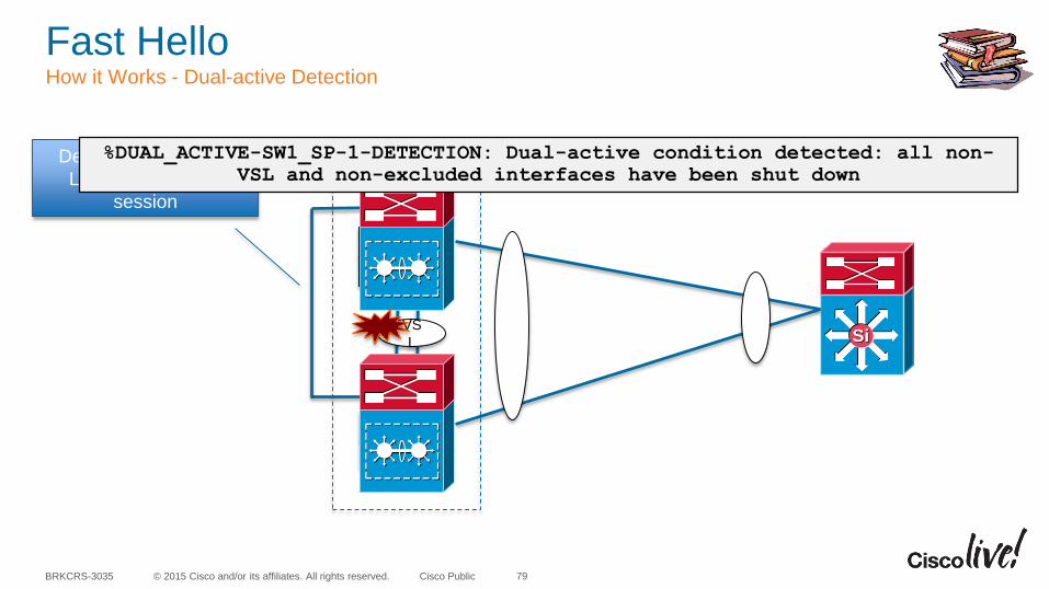
Fast Hello How it Works - Dual-active Detection
79
SiSi
Switch 2
Switch 1
Active
Standby
VS
L
VSSDedicated Heartbeat
Link for Fast Hello
session
%DUAL_ACTIVE-SW1_SP-1-DETECTION: Dual-active condition detected: all non-
VSL and non-excluded interfaces have been shut down
© 2015 Cisco and/or its affiliates. All rights reserved.BRKCRS-3035 Cisco Public
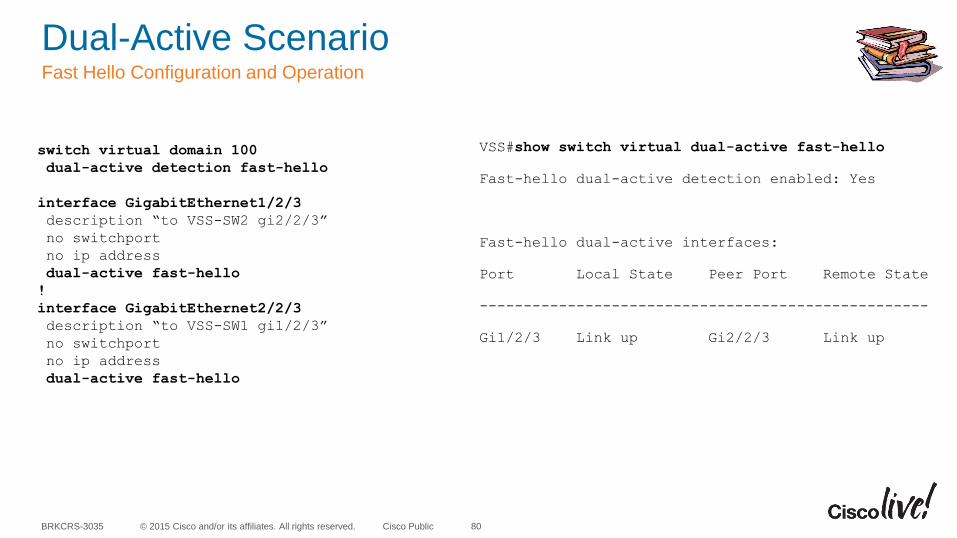
Dual-Active ScenarioFast Hello Configuration and Operation
80
VSS#show switch virtual dual-active fast-hello
Fast-hello dual-active detection enabled: Yes
Fast-hello dual-active interfaces:
Port Local State Peer Port Remote State
---------------------------------------------------
Gi1/2/3 Link up Gi2/2/3 Link up
switch virtual domain 100
dual-active detection fast-hello
interface GigabitEthernet1/2/3
description “to VSS-SW2 gi2/2/3”
no switchport
no ip address
dual-active fast-hello
!
interface GigabitEthernet2/2/3
description “to VSS-SW1 gi1/2/3”
no switchport
no ip address
dual-active fast-hello
© 2015 Cisco and/or its affiliates. All rights reserved.BRKCRS-3035 Cisco Public
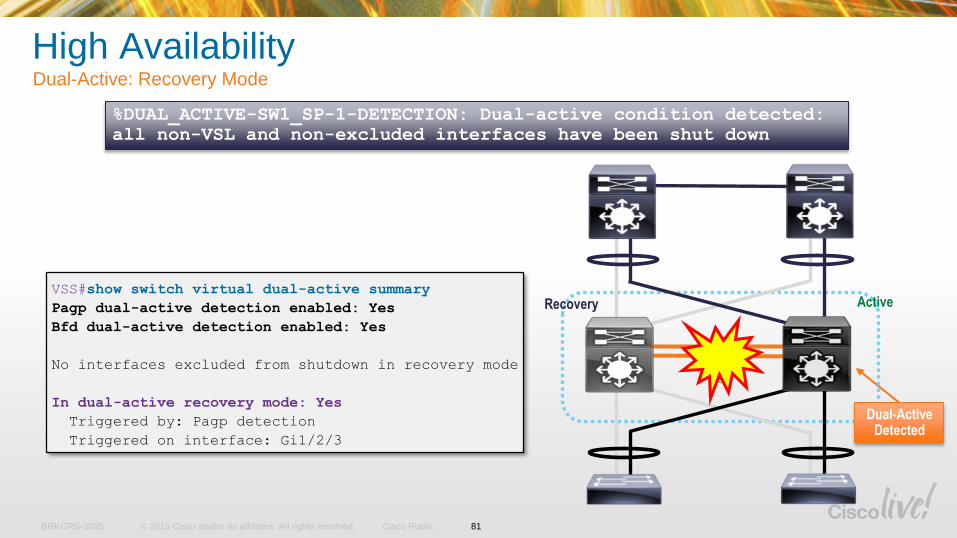
%DUAL_ACTIVE-SW1_SP-1-DETECTION: Dual-active condition detected:
all non-VSL and non-excluded interfaces have been shut down
VSS#show switch virtual dual-active summary
Pagp dual-active detection enabled: Yes
Bfd dual-active detection enabled: Yes
No interfaces excluded from shutdown in recovery mode
In dual-active recovery mode: Yes
Triggered by: Pagp detection
Triggered on interface: Gi1/2/3
High AvailabilityDual-Active: Recovery Mode
VSL
Dual-Active Detected
Recovery Active
81
© 2015 Cisco and/or its affiliates. All rights reserved.BRKCRS-3035 Cisco Public
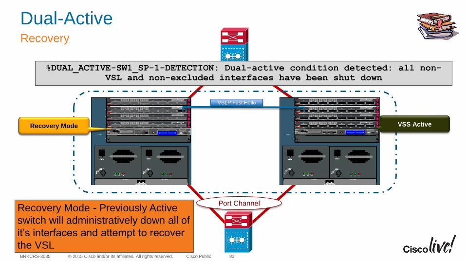
Dual-ActiveRecovery
82
VSS Active VSS Active
Port Channel
Port Channel
%DUAL_ACTIVE-SW1_SP-1-DETECTION: Dual-active condition detected: all non-
VSL and non-excluded interfaces have been shut down
VSLP Fast Hello
Recovery Mode
Recovery Mode - Previously Active
switch will administratively down all of
it’s interfaces and attempt to recover
the VSL
© 2015 Cisco and/or its affiliates. All rights reserved.BRKCRS-3035 Cisco Public
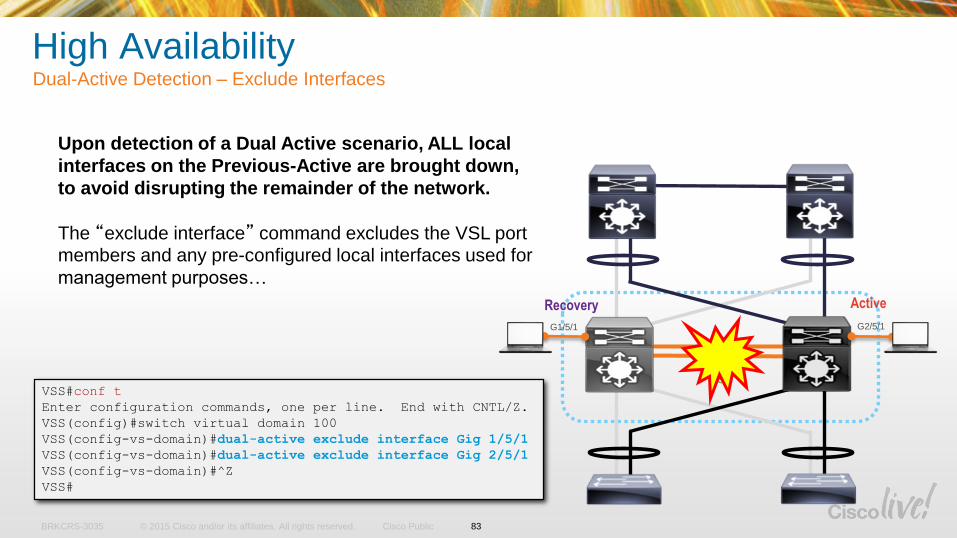
High AvailabilityDual-Active Detection – Exclude Interfaces
Upon detection of a Dual Active scenario, ALL local
interfaces on the Previous-Active are brought down,
to avoid disrupting the remainder of the network.
The “exclude interface” command excludes the VSL port
members and any pre-configured local interfaces used for
management purposes…
VSS#conf t
Enter configuration commands, one per line. End with CNTL/Z.
VSS(config)#switch virtual domain 100
VSS(config-vs-domain)#dual-active exclude interface Gig 1/5/1
VSS(config-vs-domain)#dual-active exclude interface Gig 2/5/1
VSS(config-vs-domain)#^Z
VSS#
VSL
Recovery Active
G1/5/1 G2/5/1
83
© 2015 Cisco and/or its affiliates. All rights reserved.BRKCRS-3035 Cisco Public
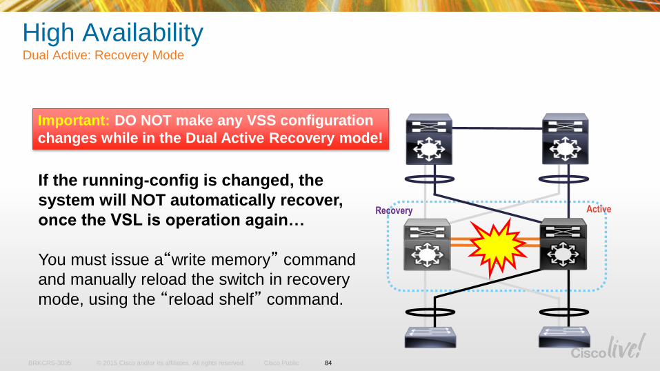
High AvailabilityDual Active: Recovery Mode
Important: DO NOT make any VSS configuration
changes while in the Dual Active Recovery mode!
If the running-config is changed, the
system will NOT automatically recover,
once the VSL is operation again…
You must issue a“write memory” command
and manually reload the switch in recovery
mode, using the “reload shelf” command.
VSL
Recovery Active
84
© 2015 Cisco and/or its affiliates. All rights reserved.BRKCRS-3035 Cisco Public
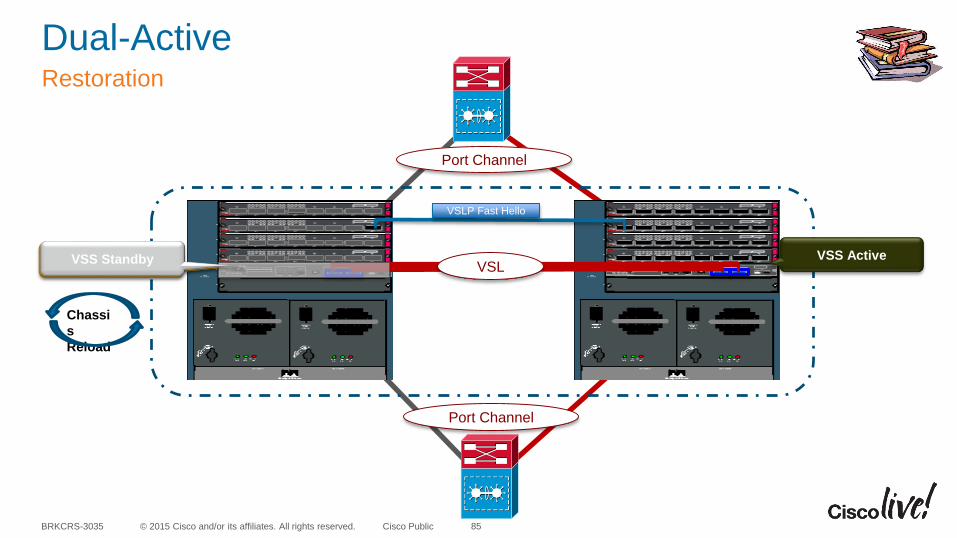
Dual-ActiveRestoration
85
VSS Active
Port Channel
Port Channel
VSLP Fast Hello
Recovery Mode VSL
Chassi
s
Reload
VSS Standby

VSS Supervisor Engine Redundancy
© 2015 Cisco and/or its affiliates. All rights reserved.BRKCRS-3035 Cisco Public
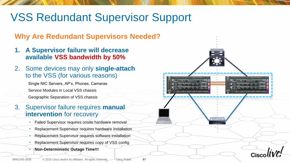
VSS Redundant Supervisor Support
1. A Supervisor failure will decrease available VSS bandwidth by 50%
2. Some devices may only single-attach to the VSS (for various reasons)
Single NIC Servers, AP’s, Phones, Cameras
Service Modules in Local VSS chassis
Geographic Separation of VSS chassis
3. Supervisor failure requires manual intervention for recovery
• Failed Supervisor requires onsite hardware removal
• Replacement Supervisor requires hardware installation
• Replacement Supervisor requires software installation
• Replacement Supervisor requires copy of VSS config
• Non-Deterministic Outage Time!!!
Why Are Redundant Supervisors Needed?
87
© 2015 Cisco and/or its affiliates. All rights reserved.BRKCRS-3035 Cisco Public
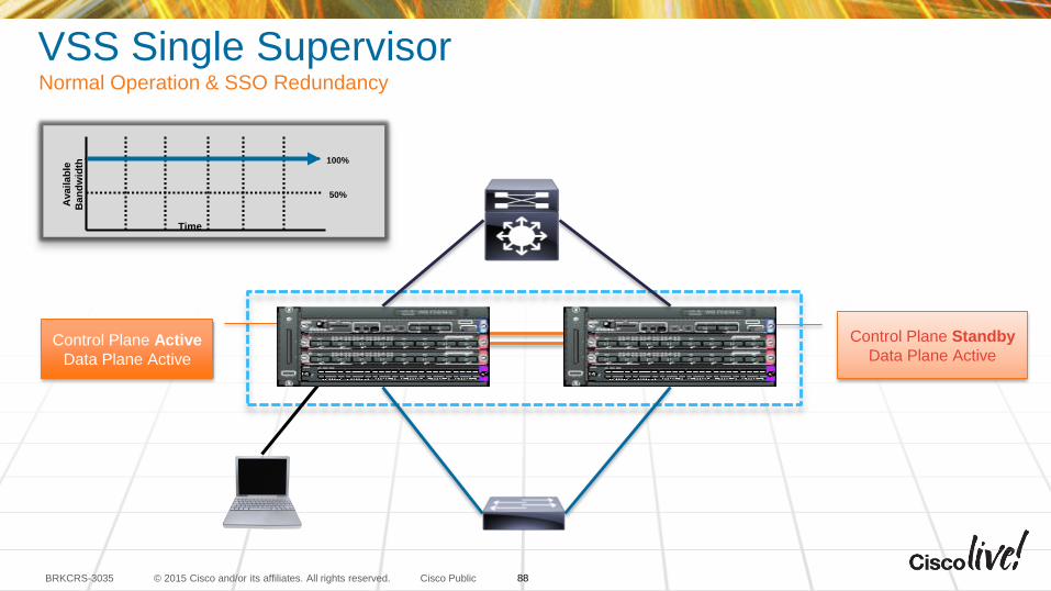
Control Plane Standby
Data Plane Active
VSS Single Supervisor Normal Operation & SSO Redundancy
Control Plane Active
Data Plane Active
100%
50%
Availab
le
Ban
dw
idth
Time
88
© 2015 Cisco and/or its affiliates. All rights reserved.BRKCRS-3035 Cisco Public
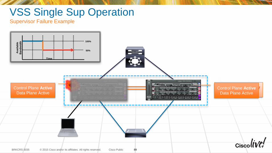
VSS Single Sup OperationSupervisor Failure Example
Control Plane Active
Data Plane Active
100%
50%
Availab
le
Ban
dw
idth
Time
Control Plane Standby
Data Plane ActiveControl Plane Active
Data Plane Active
89
© 2015 Cisco and/or its affiliates. All rights reserved.BRKCRS-3035 Cisco Public
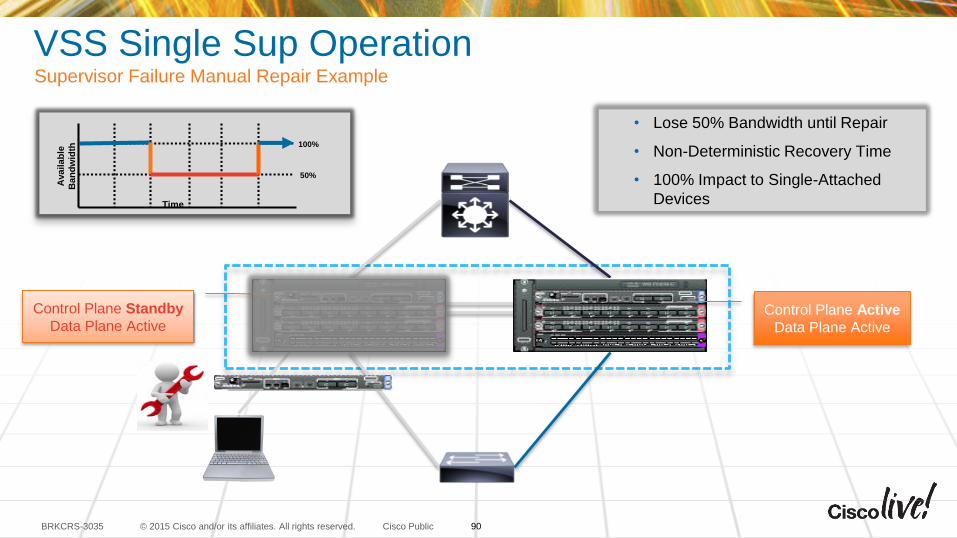
VSS Single Sup OperationSupervisor Failure Manual Repair Example
• Lose 50% Bandwidth until Repair
• Non-Deterministic Recovery Time
• 100% Impact to Single-Attached
Devices
Control Plane Standby
Data Plane Active
100%
50%
Availab
le
Ban
dw
idth
Time
Control Plane Active
Data Plane Active
90
© 2015 Cisco and/or its affiliates. All rights reserved.BRKCRS-3035 Cisco Public
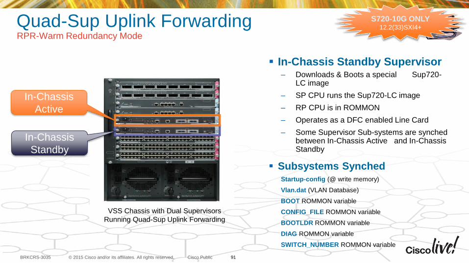
Quad-Sup Uplink Forwarding RPR-Warm Redundancy Mode
In-Chassis Standby Supervisor– Downloads & Boots a special Sup720-
LC image
– SP CPU runs the Sup720-LC image
– RP CPU is in ROMMON
– Operates as a DFC enabled Line Card
– Some Supervisor Sub-systems are synched between In-Chassis Active and In-Chassis Standby
Subsystems SynchedStartup-config (@ write memory)
Vlan.dat (VLAN Database)
BOOT ROMMON variable
CONFIG_FILE ROMMON variable
BOOTLDR ROMMON variable
DIAG ROMMON variable
SWITCH_NUMBER ROMMON variable
VSS Chassis with Dual Supervisors
Running Quad-Sup Uplink Forwarding
In-Chassis
Active
In-Chassis
Standby
91
S720-10G ONLY12.2(33)SXI4+
© 2015 Cisco and/or its affiliates. All rights reserved.BRKCRS-3035 Cisco Public
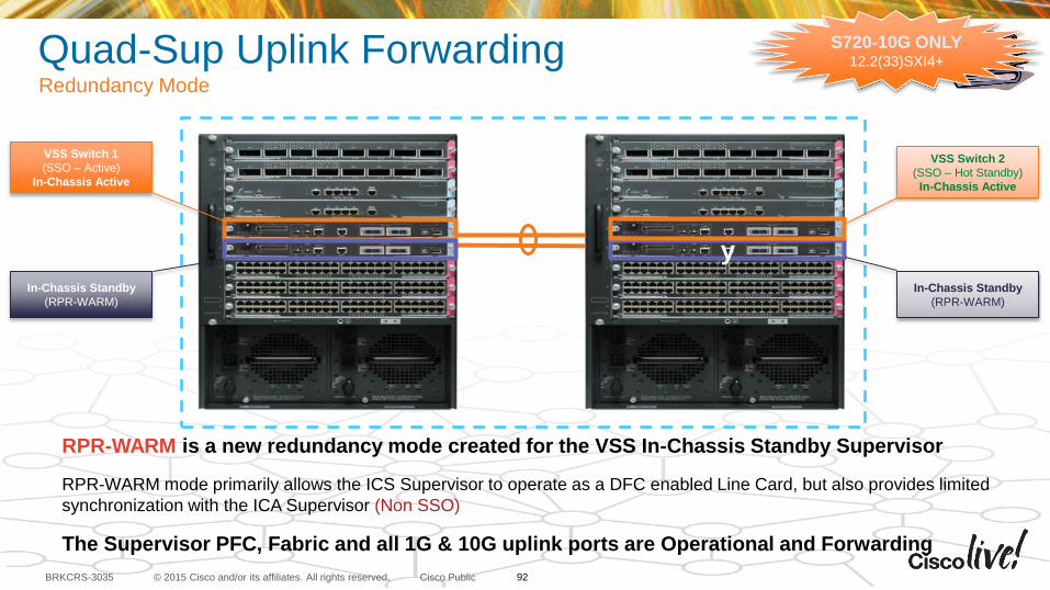
Quad-Sup Uplink Forwarding Redundancy Mode
VSS Switch 1
(SSO – Active)
In-Chassis Active
In-Chassis Standby
(RPR-WARM)
y
In-Chassis Standby
(RPR-WARM)
RPR-WARM is a new redundancy mode created for the VSS In-Chassis Standby Supervisor
RPR-WARM mode primarily allows the ICS Supervisor to operate as a DFC enabled Line Card, but also provides limited
synchronization with the ICA Supervisor (Non SSO)
The Supervisor PFC, Fabric and all 1G & 10G uplink ports are Operational and Forwarding
VSS Switch 2
(SSO – Hot Standby)
In-Chassis Active
92
S720-10G ONLY12.2(33)SXI4+
© 2015 Cisco and/or its affiliates. All rights reserved.BRKCRS-3035 Cisco Public
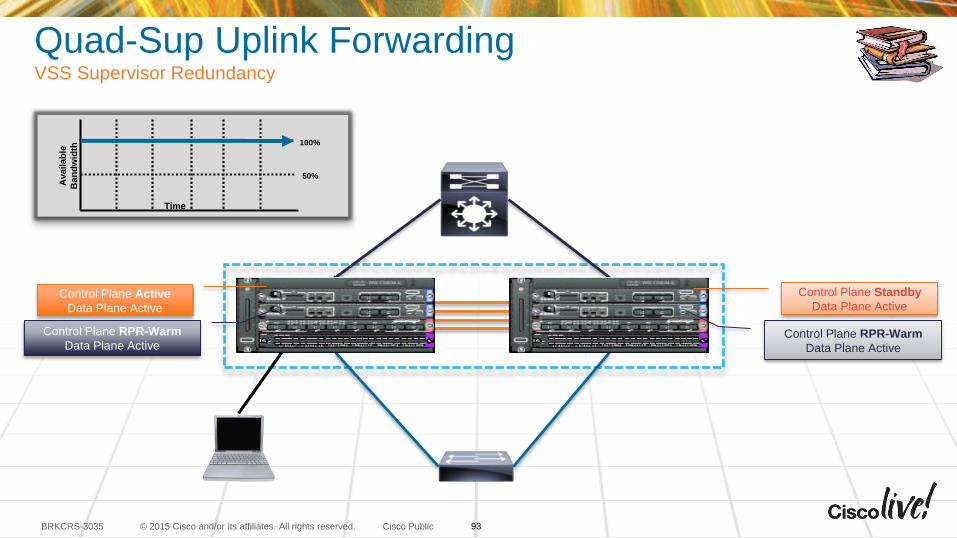
Quad-Sup Uplink ForwardingVSS Supervisor Redundancy
100%
50%
Availab
le
Ban
dw
idth
Time
Control Plane RPR-Warm
Data Plane Active
Control Plane Active
Data Plane Active
Control Plane Standby
Data Plane Active
Control Plane RPR-Warm
Data Plane Active
93
© 2015 Cisco and/or its affiliates. All rights reserved.BRKCRS-3035 Cisco Public
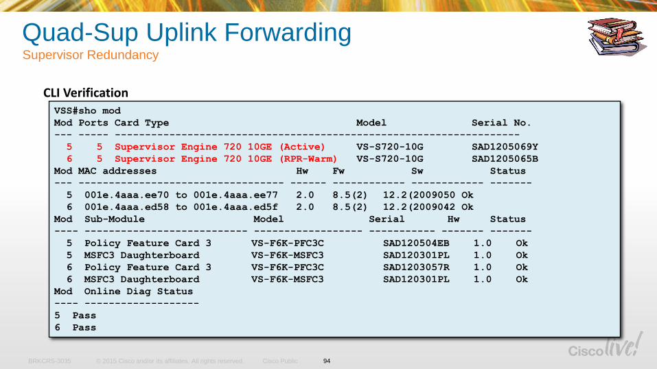
CLI Verification VSS#sho mod
Mod Ports Card Type Model Serial No.
--- ----- -------------------------------------------------------------------
5 5 Supervisor Engine 720 10GE (Active) VS-S720-10G SAD1205069Y
6 5 Supervisor Engine 720 10GE (RPR-Warm) VS-S720-10G SAD1205065B
Mod MAC addresses Hw Fw Sw Status
--- ---------------------------------- ------ ------------ ------------ -------
5 001e.4aaa.ee70 to 001e.4aaa.ee77 2.0 8.5(2) 12.2(2009050 Ok
6 001e.4aaa.ed58 to 001e.4aaa.ed5f 2.0 8.5(2) 12.2(2009042 Ok
Mod Sub-Module Model Serial Hw Status
---- --------------------------- ------------------ ----------- ------- -------
5 Policy Feature Card 3 VS-F6K-PFC3C SAD120504EB 1.0 Ok
5 MSFC3 Daughterboard VS-F6K-MSFC3 SAD120301PL 1.0 Ok
6 Policy Feature Card 3 VS-F6K-PFC3C SAD1203057R 1.0 Ok
6 MSFC3 Daughterboard VS-F6K-MSFC3 SAD120301PL 1.0 Ok
Mod Online Diag Status
---- -------------------
5 Pass
6 Pass
Quad-Sup Uplink Forwarding Supervisor Redundancy
94
© 2015 Cisco and/or its affiliates. All rights reserved.BRKCRS-3035 Cisco Public
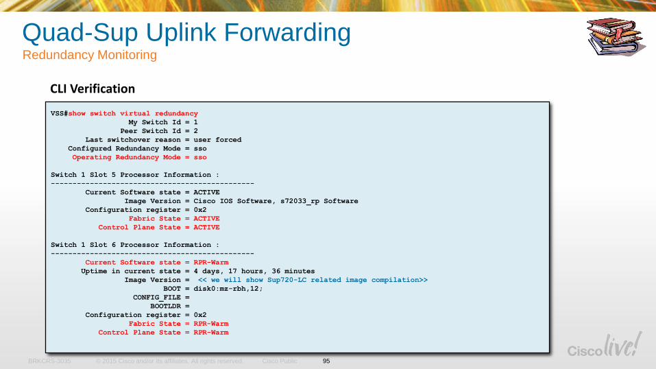
CLI Verification
VSS#show switch virtual redundancy
My Switch Id = 1
Peer Switch Id = 2
Last switchover reason = user forced
Configured Redundancy Mode = sso
Operating Redundancy Mode = sso
Switch 1 Slot 5 Processor Information :
-----------------------------------------------
Current Software state = ACTIVE
Image Version = Cisco IOS Software, s72033_rp Software
Configuration register = 0x2
Fabric State = ACTIVE
Control Plane State = ACTIVE
Switch 1 Slot 6 Processor Information :
-----------------------------------------------
Current Software state = RPR-Warm
Uptime in current state = 4 days, 17 hours, 36 minutes
Image Version = << we will show Sup720-LC related image compilation>>
BOOT = disk0:mz-rbh,12;
CONFIG_FILE =
BOOTLDR =
Configuration register = 0x2
Fabric State = RPR-Warm
Control Plane State = RPR-Warm
Quad-Sup Uplink Forwarding Redundancy Monitoring
95
© 2015 Cisco and/or its affiliates. All rights reserved.BRKCRS-3035 Cisco Public
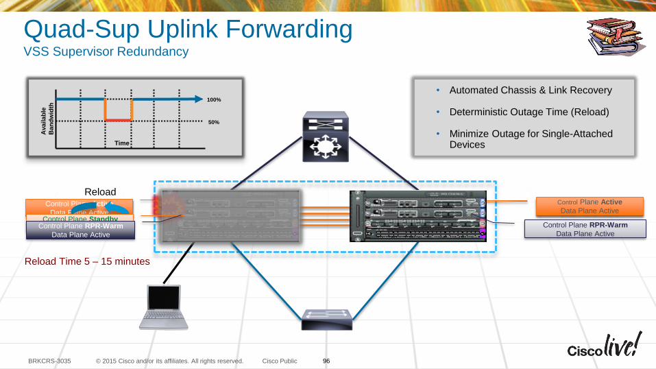
• Automated Chassis & Link Recovery
• Deterministic Outage Time (Reload)
• Minimize Outage for Single-Attached Devices
Control Plane Standby
Data Plane ActiveControl Plane Active
Data Plane Active
Reload
Control Plane Standby
Data Plane Active
Control Plane Active
Data Plane Active
Control Plane RPR-Warm
Data Plane Active
Control Plane RPR-Warm
Data Plane Active
100%
50%
Availab
le
Ban
dw
idth
Time
Reload Time 5 – 15 minutes
Quad-Sup Uplink ForwardingVSS Supervisor Redundancy
96
© 2015 Cisco and/or its affiliates. All rights reserved.BRKCRS-3035 Cisco Public
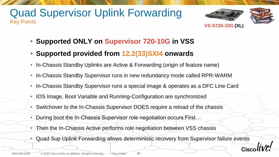
Quad Supervisor Uplink Forwarding Key Points
• Supported ONLY on Supervisor 720-10G in VSS
• Supported provided from 12.2(33)SXI4 onwards
• In-Chassis Standby Uplinks are Active & Forwarding (origin of feature name)
• In-Chassis Standby Supervisor runs in new redundancy mode called RPR-WARM
• In-Chassis Standby Supervisor runs a special image & operates as a DFC Line Card
• IOS Image, Boot Variable and Running-Configuration are synchronized
• Switchover to the In-Chassis Supervisor DOES require a reload of the chassis
• During boot the In-Chassis Supervisor role negotiation occurs First…
• Then the In-Chassis Active performs role negotiation between VSS chassis
• Quad Sup Uplink Forwarding allows deterministic recovery from Supervisor failure events
VS-S720-10G (XL)
97
VSS Quad-Sup SSOCatalyst 6500 / 6800
Sup2T Only
with IOS 15.1(1)SY1+
© 2015 Cisco and/or its affiliates. All rights reserved.BRKCRS-3035 Cisco Public
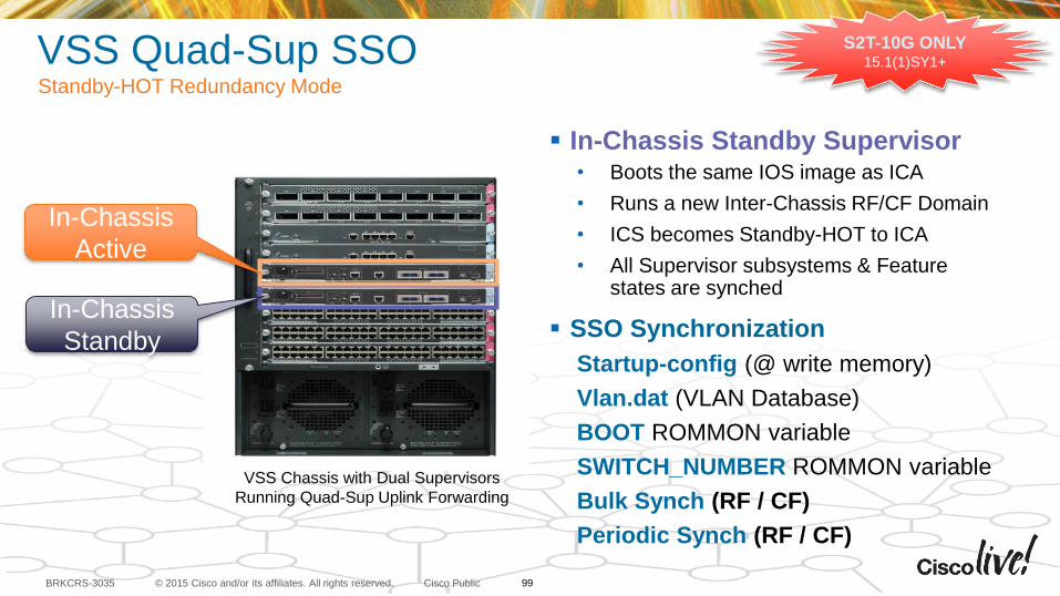
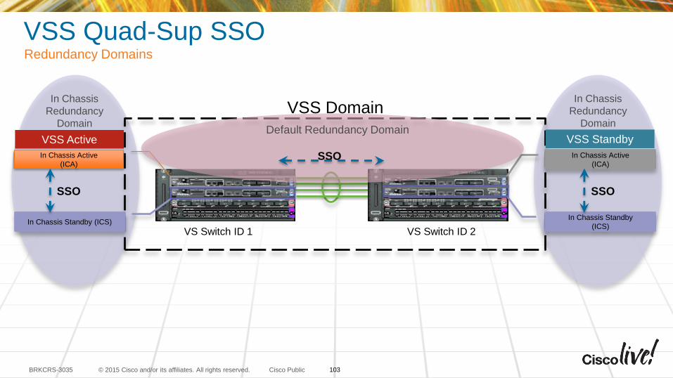
VSS Quad-Sup SSOStandby-HOT Redundancy Mode
In-Chassis Standby Supervisor• Boots the same IOS image as ICA
• Runs a new Inter-Chassis RF/CF Domain
• ICS becomes Standby-HOT to ICA
• All Supervisor subsystems & Feature states are synched
SSO Synchronization
Startup-config (@ write memory)
Vlan.dat (VLAN Database)
BOOT ROMMON variable
SWITCH_NUMBER ROMMON variable
Bulk Synch (RF / CF)
Periodic Synch (RF / CF)
VSS Chassis with Dual Supervisors
Running Quad-Sup Uplink Forwarding
In-Chassis
Active
In-Chassis
Standby
S2T-10G ONLY15.1(1)SY1+
99
© 2015 Cisco and/or its affiliates. All rights reserved.BRKCRS-3035 Cisco Public
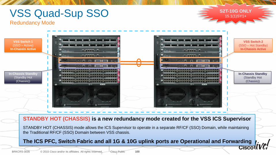
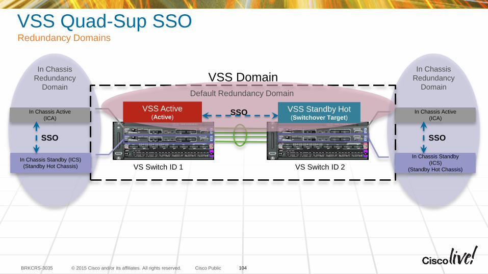
VSS Quad-Sup SSORedundancy Mode
VSS Switch 1
(SSO – Active)
In-Chassis Active
In-Chassis Standby
(Standby Hot
(Chassis))
In-Chassis Standby
(Standby Hot
(Chassis))
STANDBY HOT (CHASSIS) is a new redundancy mode created for the VSS ICS Supervisor
STANDBY HOT (CHASSIS) mode allows the ICS Supervisor to operate in a separate RF/CF (SSO) Domain, while maintaining
the Traditional RF/CF (SSO) Domain between VSS chassis.
The ICS PFC, Switch Fabric and all 1G & 10G uplink ports are Operational and Forwarding
VSS Switch 2
(SSO – Hot Standby)
In-Chassis Active
S2T-10G ONLY15.1(1)SY1+
100
© 2015 Cisco and/or its affiliates. All rights reserved.BRKCRS-3035 Cisco Public
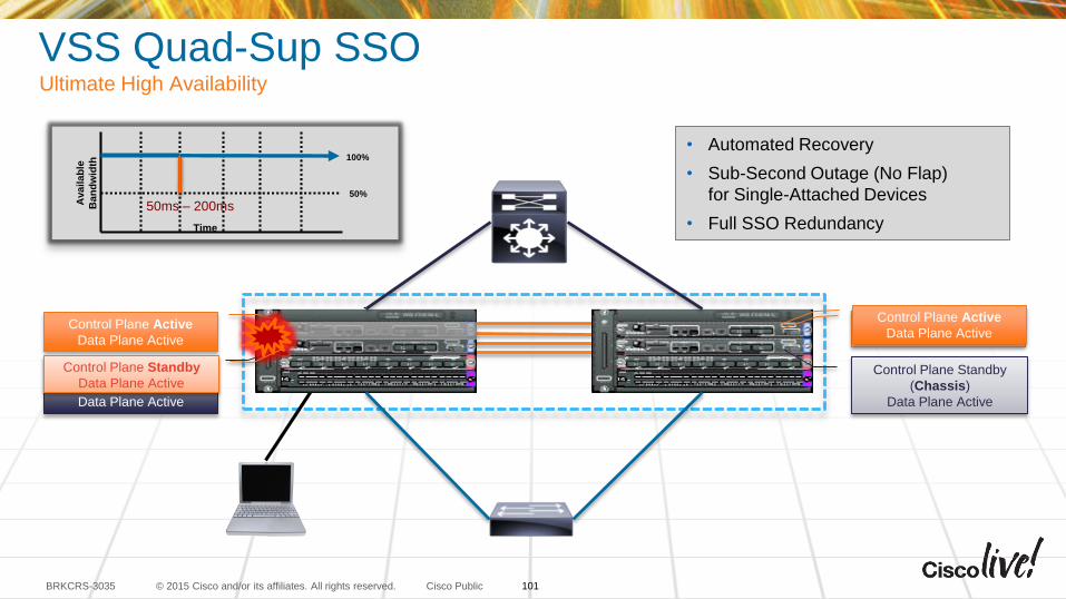
VSS Quad-Sup SSOUltimate High Availability
• Automated Recovery
• Sub-Second Outage (No Flap)
for Single-Attached Devices
• Full SSO Redundancy
Control Plane Standby
(Chassis)
Data Plane Active
Control Plane Active
Data Plane Active
Control Plane Standby
Data Plane Active
Control Plane Standby
(Chassis)
Data Plane Active
Control Plane Active
Data Plane Active
100%
50%
Availab
le
Ban
dw
idth
Time
50ms – 200ms
Control Plane Standby
Data Plane Active
101
© 2015 Cisco and/or its affiliates. All rights reserved.BRKCRS-3035 Cisco Public
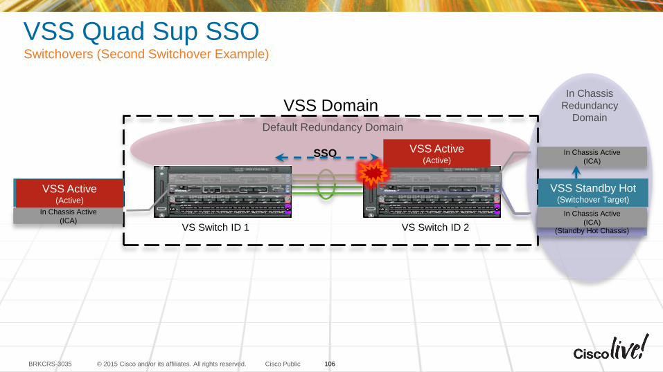
ICS
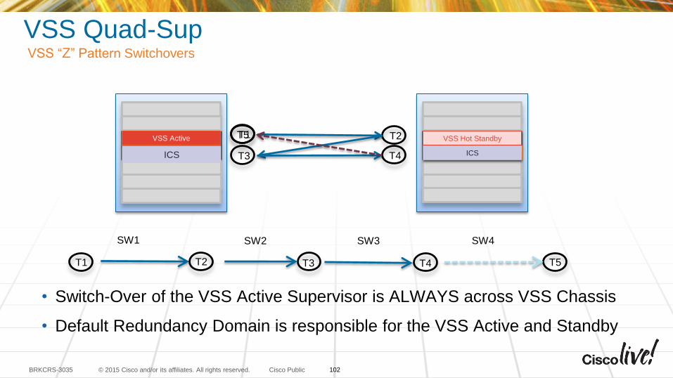
VSS Quad-SupVSS “Z” Pattern Switchovers
• Switch-Over of the VSS Active Supervisor is ALWAYS across VSS Chassis
• Default Redundancy Domain is responsible for the VSS Active and Standby
VSS Active VSS Hot Standby
ICS ICS
VSS Active
VSS Hot Standby
ICS
ICSVSS Active VSS Hot Standby
ICS ICS
VSS Active
VSS Hot Standby
ICS
ICST1
T1
T2
T2
T3
T3
T4
T4 T5
T5
SW1 SW2 SW3 SW4
VSS Active
ICS
VSS Hot Standby
ICS
102
© 2015 Cisco and/or its affiliates. All rights reserved.BRKCRS-3035 Cisco Public
In Chassis
Redundancy
Domain
In Chassis
Redundancy
Domain
VSS Quad-Sup SSORedundancy Domains
VSS Domain
In Chassis Active
(ICA)
In Chassis Standby (ICS)
In Chassis Active
(ICA)
In Chassis Standby
(ICS)VS Switch ID 1 VS Switch ID 2
VSS Active VSS Standby
SSO SSO
Default Redundancy Domain
SSO
103
© 2015 Cisco and/or its affiliates. All rights reserved.BRKCRS-3035 Cisco Public
In Chassis
Redundancy
Domain
In Chassis
Redundancy
Domain
VSS Quad-Sup SSORedundancy Domains
VSS Domain
In Chassis Active
(ICA)
In Chassis Standby (ICS)
(Standby Hot Chassis)
In Chassis Active
(ICA)
In Chassis Standby
(ICS)
(Standby Hot Chassis)VS Switch ID 1 VS Switch ID 2
Default Redundancy Domain
SSOVSS Active(Active)
VSS Standby Hot(Switchover Target)
SSO SSO
104
© 2015 Cisco and/or its affiliates. All rights reserved.BRKCRS-3035 Cisco Public
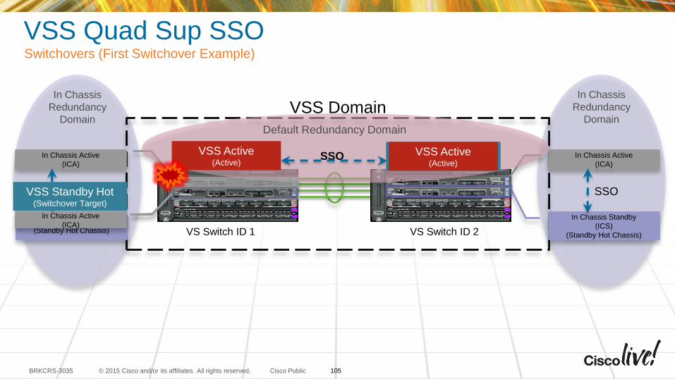
VSS Quad Sup SSOSwitchovers (First Switchover Example)
In Chassis
Redundancy
Domain
In Chassis
Redundancy
DomainVSS Domain
In Chassis Active
(ICA)
In Chassis Standby (ICS)
(Standby Hot Chassis)
In Chassis Active
(ICA)
In Chassis Standby
(ICS)
(Standby Hot Chassis)VS Switch ID 1 VS Switch ID 2
Default Redundancy Domain
SSOVSS Active(Active)
VSS Standby Hot(Switchover Target)
SSO SSO
VSS Active(Active)
VSS Standby Hot(Switchover Target)
In Chassis Active
(ICA)
105
© 2015 Cisco and/or its affiliates. All rights reserved.BRKCRS-3035 Cisco Public
Default Redundancy Domain
VSS Quad Sup SSOSwitchovers (Second Switchover Example)
In Chassis
Redundancy
DomainVSS Domain
In Chassis Active
(ICA)
In Chassis Standby
(ICS)
(Standby Hot Chassis)VS Switch ID 1 VS Switch ID 2
SSO
SSO
VSS Active(Active)
VSS Standby Hot(Switchover Target)
In Chassis Active
(ICA)
VSS Active(Active)
VSS Standby Hot(Switchover Target)
In Chassis Active
(ICA)
106
© 2015 Cisco and/or its affiliates. All rights reserved.BRKCRS-3035 Cisco Public
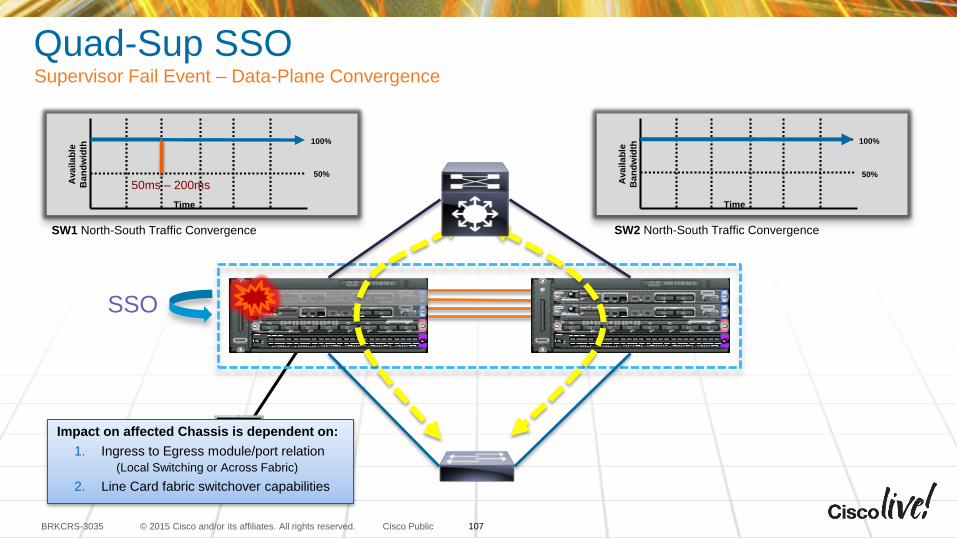
Quad-Sup SSO Supervisor Fail Event – Data-Plane Convergence
SSO
SW1 North-South Traffic Convergence SW2 North-South Traffic Convergence
100%
50%
Availab
le
Ban
dw
idth
Time
50ms – 200ms
100%
50%
Availab
le
Ban
dw
idth
Time
Impact on affected Chassis is dependent on:
1. Ingress to Egress module/port relation
(Local Switching or Across Fabric)
2. Line Card fabric switchover capabilities
107
© 2015 Cisco and/or its affiliates. All rights reserved.BRKCRS-3035 Cisco Public
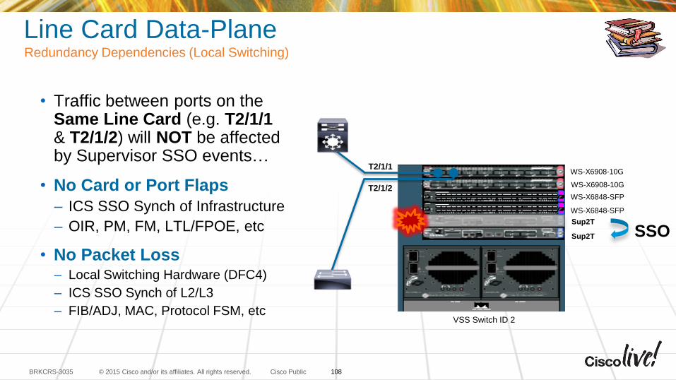
Line Card Data-PlaneRedundancy Dependencies (Local Switching)
• Traffic between ports on the Same Line Card (e.g. T2/1/1 & T2/1/2) will NOT be affected by Supervisor SSO events…
• No Card or Port Flaps
– ICS SSO Synch of Infrastructure
– OIR, PM, FM, LTL/FPOE, etc
• No Packet Loss– Local Switching Hardware (DFC4)
– ICS SSO Synch of L2/L3
– FIB/ADJ, MAC, Protocol FSM, etc
WS-X6908-10G
WS-X6848-SFP
Sup2T
Sup2T
WS-X6908-10G
WS-X6848-SFP
T2/1/1
T2/1/2
SSO
VSS Switch ID 2
108
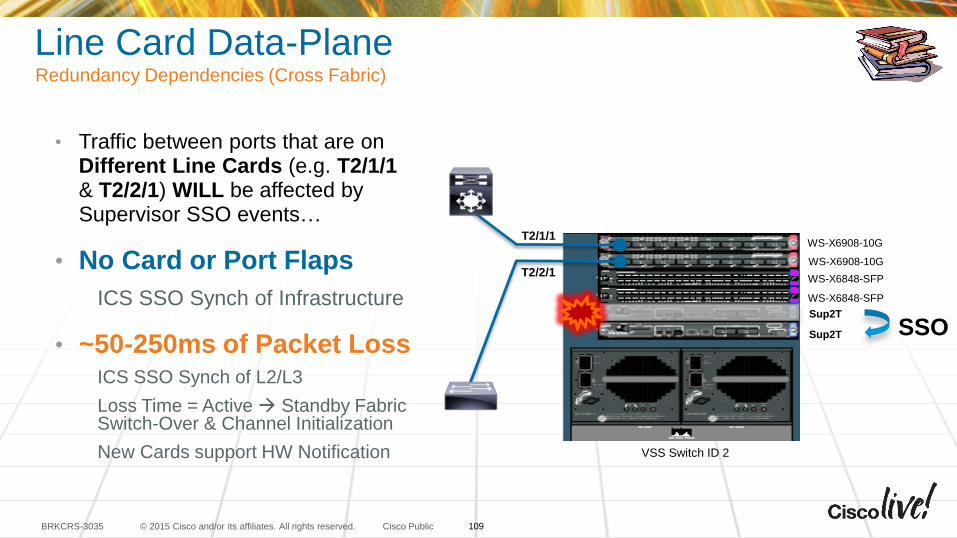
© 2015 Cisco and/or its affiliates. All rights reserved.BRKCRS-3035 Cisco Public
Line Card Data-PlaneRedundancy Dependencies (Cross Fabric)
WS-X6908-10G
WS-X6848-SFP
Sup2T
Sup2T
WS-X6908-10G
WS-X6848-SFP
T2/1/1
T2/2/1
SSO
VSS Switch ID 2
• Traffic between ports that are on Different Line Cards (e.g. T2/1/1 & T2/2/1) WILL be affected by Supervisor SSO events…
• No Card or Port Flaps
ICS SSO Synch of Infrastructure
• ~50-250ms of Packet LossICS SSO Synch of L2/L3
Loss Time = Active Standby Fabric Switch-Over & Channel Initialization
New Cards support HW Notification
109
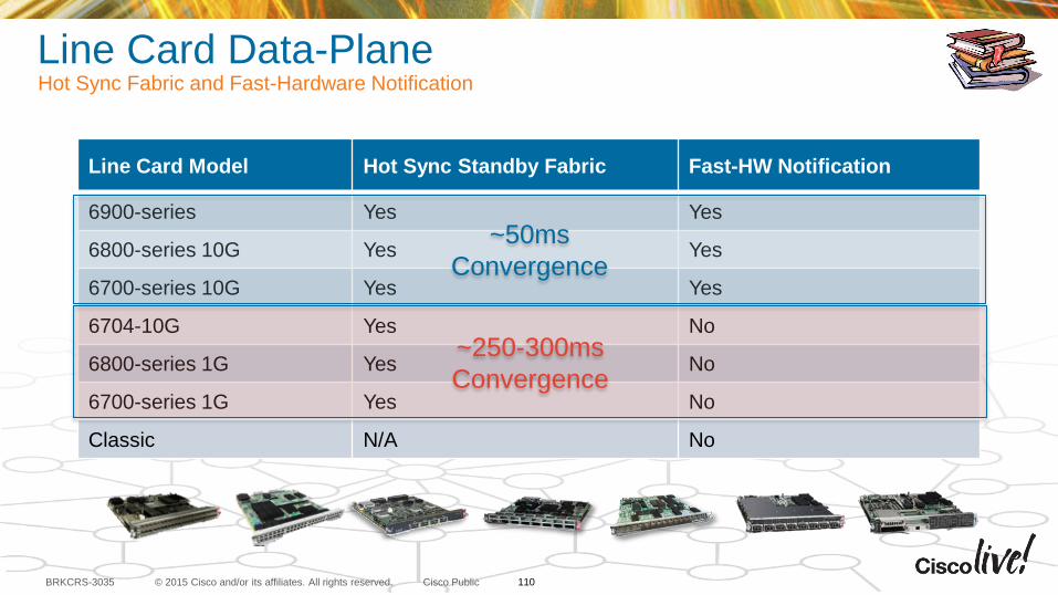
© 2015 Cisco and/or its affiliates. All rights reserved.BRKCRS-3035 Cisco Public
Line Card Data-PlaneHot Sync Fabric and Fast-Hardware Notification
Line Card Model Hot Sync Standby Fabric Fast-HW Notification
6900-series Yes Yes
6800-series 10G Yes Yes
6700-series 10G Yes Yes
6704-10G Yes No
6800-series 1G Yes No
6700-series 1G Yes No
Classic N/A No
~50ms
Convergence
~250-300ms
Convergence
110
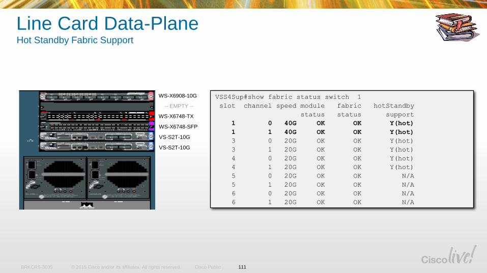
© 2015 Cisco and/or its affiliates. All rights reserved.BRKCRS-3035 Cisco Public
Line Card Data-Plane Hot Standby Fabric Support
VSS4Sup#show fabric status switch 1
slot channel speed module fabric hotStandby
status status support
1 0 40G OK OK Y(hot)
1 1 40G OK OK Y(hot)
3 0 20G OK OK Y(hot)
3 1 20G OK OK Y(hot)
4 0 20G OK OK Y(hot)
4 1 20G OK OK Y(hot)
5 0 20G OK OK N/A
5 1 20G OK OK N/A
6 0 20G OK OK N/A
6 1 20G OK OK N/A
WS-X6908-10G
WS-X6748-TX
WS-X6748-SFP
VS-S2T-10G
VS-S2T-10G
-- EMPTY --
111
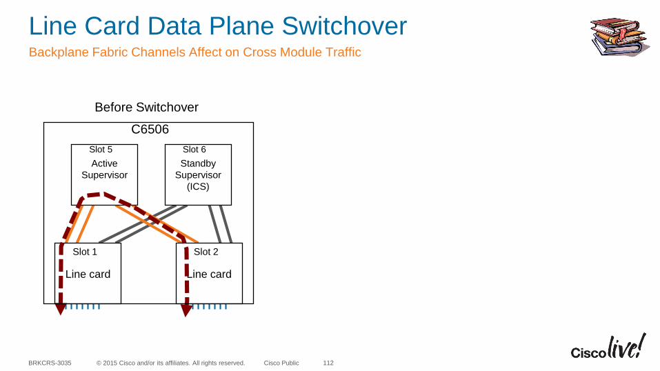
© 2015 Cisco and/or its affiliates. All rights reserved.BRKCRS-3035 Cisco Public
Line Card Data Plane Switchover Backplane Fabric Channels Affect on Cross Module Traffic
112
Active
Supervisor
Standby
Supervisor
(ICS)
Line card Line card
Slot 5 Slot 6
Slot 1 Slot 2
C6506
Before Switchover
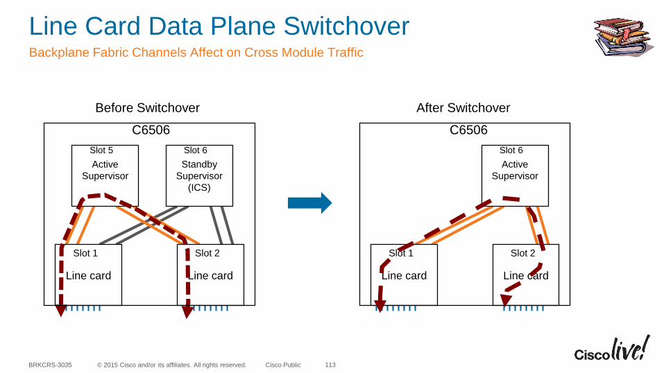
© 2015 Cisco and/or its affiliates. All rights reserved.BRKCRS-3035 Cisco Public
Line Card Data Plane Switchover Backplane Fabric Channels Affect on Cross Module Traffic
113
Active
Supervisor
Standby
Supervisor
(ICS)
Line card Line card
Slot 5 Slot 6
Slot 1 Slot 2
Active
Supervisor
Line card Line card
Slot 6
Slot 1 Slot 2
C6506C6506
Before Switchover After Switchover
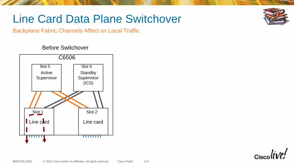
© 2015 Cisco and/or its affiliates. All rights reserved.BRKCRS-3035 Cisco Public
Line Card Data Plane Switchover Backplane Fabric Channels Affect on Local Traffic
114
Active
Supervisor
Standby
Supervisor
(ICS)
Line card Line card
Slot 5 Slot 6
Slot 1 Slot 2
C6506
Before Switchover
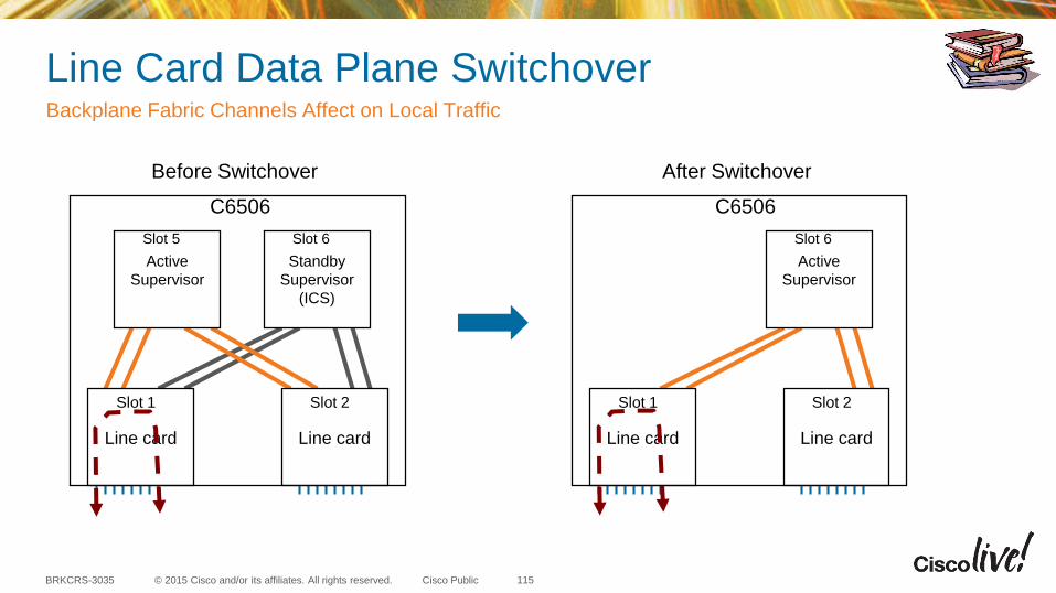
© 2015 Cisco and/or its affiliates. All rights reserved.BRKCRS-3035 Cisco Public
Line Card Data Plane Switchover Backplane Fabric Channels Affect on Local Traffic
115
Active
Supervisor
Standby
Supervisor
(ICS)
Line card Line card
Slot 5 Slot 6
Slot 1 Slot 2
Active
Supervisor
Line card Line card
Slot 6
Slot 1 Slot 2
C6506C6506
Before Switchover After Switchover
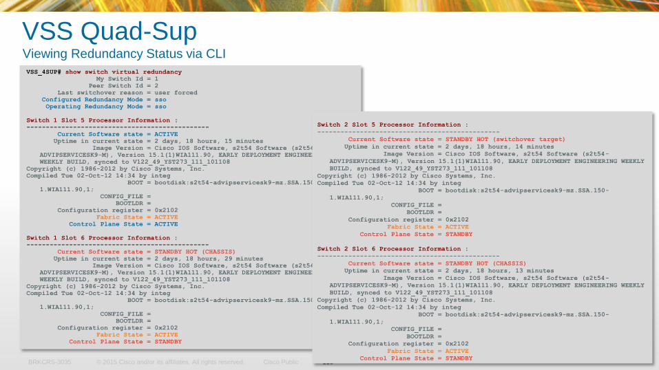
© 2015 Cisco and/or its affiliates. All rights reserved.BRKCRS-3035 Cisco Public 116
VSS Quad-SupViewing Redundancy Status via CLI
VSS_4SUP# show switch virtual redundancy
My Switch Id = 1
Peer Switch Id = 2
Last switchover reason = user forced
Configured Redundancy Mode = sso
Operating Redundancy Mode = sso
Switch 1 Slot 5 Processor Information :
-----------------------------------------------
Current Software state = ACTIVE
Uptime in current state = 2 days, 18 hours, 15 minutes
Image Version = Cisco IOS Software, s2t54 Software (s2t54-
ADVIPSERVICESK9-M), Version 15.1(1)WIA111.90, EARLY DEPLOYMENT ENGINEERING
WEEKLY BUILD, synced to V122_49_YST273_111_101108
Copyright (c) 1986-2012 by Cisco Systems, Inc.
Compiled Tue 02-Oct-12 14:34 by integ
BOOT = bootdisk:s2t54-advipservicesk9-mz.SSA.150-
1.WIA111.90,1;
CONFIG_FILE =
BOOTLDR =
Configuration register = 0x2102
Fabric State = ACTIVE
Control Plane State = ACTIVE
Switch 1 Slot 6 Processor Information :
-----------------------------------------------
Current Software state = STANDBY HOT (CHASSIS)
Uptime in current state = 2 days, 18 hours, 29 minutes
Image Version = Cisco IOS Software, s2t54 Software (s2t54-
ADVIPSERVICESK9-M), Version 15.1(1)WIA111.90, EARLY DEPLOYMENT ENGINEERING
WEEKLY BUILD, synced to V122_49_YST273_111_101108
Copyright (c) 1986-2012 by Cisco Systems, Inc.
Compiled Tue 02-Oct-12 14:34 by integ
BOOT = bootdisk:s2t54-advipservicesk9-mz.SSA.150-
1.WIA111.90,1;
CONFIG_FILE =
BOOTLDR =
Configuration register = 0x2102
Fabric State = ACTIVE
Control Plane State = STANDBY
Switch 2 Slot 5 Processor Information :
-----------------------------------------------
Current Software state = STANDBY HOT (switchover target)
Uptime in current state = 2 days, 18 hours, 14 minutes
Image Version = Cisco IOS Software, s2t54 Software (s2t54-
ADVIPSERVICESK9-M), Version 15.1(1)WIA111.90, EARLY DEPLOYMENT ENGINEERING WEEKLY
BUILD, synced to V122_49_YST273_111_101108
Copyright (c) 1986-2012 by Cisco Systems, Inc.
Compiled Tue 02-Oct-12 14:34 by integ
BOOT = bootdisk:s2t54-advipservicesk9-mz.SSA.150-
1.WIA111.90,1;
CONFIG_FILE =
BOOTLDR =
Configuration register = 0x2102
Fabric State = ACTIVE
Control Plane State = STANDBY
Switch 2 Slot 6 Processor Information :
-----------------------------------------------
Current Software state = STANDBY HOT (CHASSIS)
Uptime in current state = 2 days, 18 hours, 13 minutes
Image Version = Cisco IOS Software, s2t54 Software (s2t54-
ADVIPSERVICESK9-M), Version 15.1(1)WIA111.90, EARLY DEPLOYMENT ENGINEERING WEEKLY
BUILD, synced to V122_49_YST273_111_101108
Copyright (c) 1986-2012 by Cisco Systems, Inc.
Compiled Tue 02-Oct-12 14:34 by integ
BOOT = bootdisk:s2t54-advipservicesk9-mz.SSA.150-
1.WIA111.90,1;
CONFIG_FILE =
BOOTLDR =
Configuration register = 0x2102
Fabric State = ACTIVE
Control Plane State = STANDBY
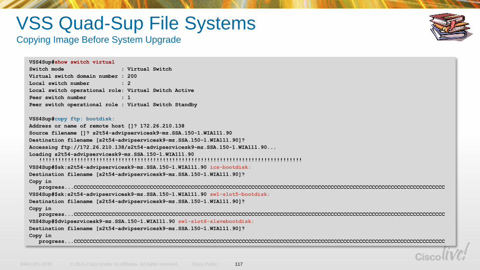
© 2015 Cisco and/or its affiliates. All rights reserved.BRKCRS-3035 Cisco Public
VSS Quad-Sup File SystemsCopying Image Before System Upgrade
VSS4Sup#show switch virtual
Switch mode : Virtual Switch
Virtual switch domain number : 200
Local switch number : 2
Local switch operational role: Virtual Switch Active
Peer switch number : 1
Peer switch operational role : Virtual Switch Standby
VSS4Sup#copy ftp: bootdisk:
Address or name of remote host []? 172.26.210.138
Source filename []? s2t54-advipservicesk9-mz.SSA.150-1.WIA111.90
Destination filename [s2t54-advipservicesk9-mz.SSA.150-1.WIA111.90]?
Accessing ftp://172.26.210.138/s2t54-advipservicesk9-mz.SSA.150-1.WIA111.90...
Loading s2t54-advipservicesk9-mz.SSA.150-1.WIA111.90
!!!!!!!!!!!!!!!!!!!!!!!!!!!!!!!!!!!!!!!!!!!!!!!!!!!!!!!!!!!!!!!!!!!!!!!!!!!!!!!!!!!
VSS4Sup#$sk:s2t54-advipservicesk9-mz.SSA.150-1.WIA111.90 ics-bootdisk:
Destination filename [s2t54-advipservicesk9-mz.SSA.150-1.WIA111.90]?
Copy in
progress...CCCCCCCCCCCCCCCCCCCCCCCCCCCCCCCCCCCCCCCCCCCCCCCCCCCCCCCCCCCCCCCCCCCCCCCCCCCCCCCCCCCCCCCCCCCCCCCCCCCCCCCCCCCCCCCCCCCCC
VSS4Sup#$sk:s2t54-advipservicesk9-mz.SSA.150-1.WIA111.90 sw1-slot5-bootdisk:
Destination filename [s2t54-advipservicesk9-mz.SSA.150-1.WIA111.90]?
Copy in
progress...CCCCCCCCCCCCCCCCCCCCCCCCCCCCCCCCCCCCCCCCCCCCCCCCCCCCCCCCCCCCCCCCCCCCCCCCCCCCCCCCCCCCCCCCCCCCCCCCCCCCCCCCCCCCCCCCCCCCC
VSS4Sup#$dvipservicesk9-mz.SSA.150-1.WIA111.90 sw1-slot6-slavebootdisk:
Destination filename [s2t54-advipservicesk9-mz.SSA.150-1.WIA111.90]?
Copy in
progress...CCCCCCCCCCCCCCCCCCCCCCCCCCCCCCCCCCCCCCCCCCCCCCCCCCCCCCCCCCCCCCCCCCCCCCCCCCCCCCCCCCCCCCCCCCCCCCCCCCCCCCCCCCCCCCCCCCCCC
117
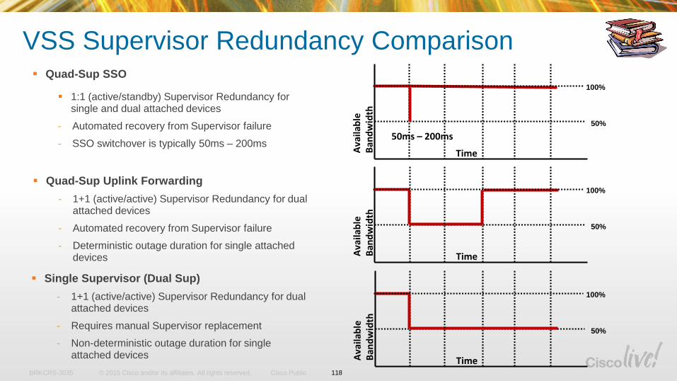
© 2015 Cisco and/or its affiliates. All rights reserved.BRKCRS-3035 Cisco Public
VSS Supervisor Redundancy Comparison
100%
50%
Ava
ilab
le
Ban
dw
idth
Time
Quad-Sup Uplink Forwarding
- 1+1 (active/active) Supervisor Redundancy for dual attached devices
- Automated recovery from Supervisor failure
- Deterministic outage duration for single attached devices
100%
50%
Ava
ilab
le
Ban
dw
idth
Time
Quad-Sup SSO
1:1 (active/standby) Supervisor Redundancy for single and dual attached devices
- Automated recovery from Supervisor failure
- SSO switchover is typically 50ms – 200ms50ms – 200ms
100%
50%
Ava
ilab
le
Ban
dw
idth
Time
Single Supervisor (Dual Sup)
- 1+1 (active/active) Supervisor Redundancy for dual attached devices
- Requires manual Supervisor replacement
- Non-deterministic outage duration for single attached devices
118
© 2015 Cisco and/or its affiliates. All rights reserved.BRKCRS-3035 Cisco Public
Migrate to VSS Quad Sup SSO
Key Steps in migrating to Quad Sup SSO
• Upgrade the existing Sup2T VSS to version 15.1(1)SY1 or above
• Establish a console connection for each supervisor module in the VSS
• Prepare the ICS supervisor module to boot the same image version as the active VSS
• Insert the redundant supervisor module into the chassis (it does not matter which VSS
chassis the redundant supervisor is inserted into first, the VSS active or VSS standby)
• Verify the newly inserted supervisor boots as the ICS
• Configure and connect the ICS supervisor TenGigabit uplink ports into the VSL
(optional, but recommended for configuration with an ICS in each chassis)
119
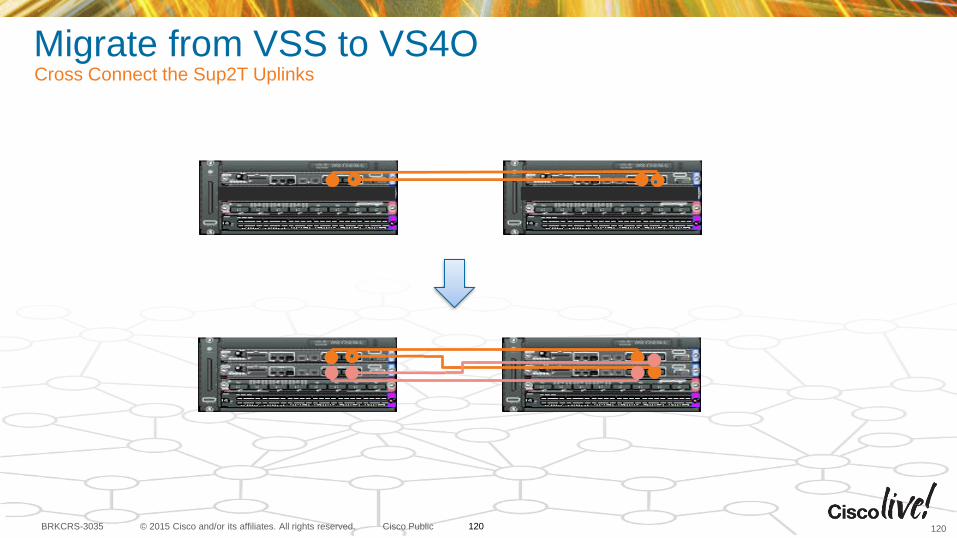
© 2015 Cisco and/or its affiliates. All rights reserved.BRKCRS-3035 Cisco Public
Migrate from VSS to VS4OCross Connect the Sup2T Uplinks
120120
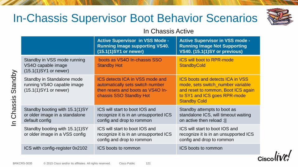
© 2015 Cisco and/or its affiliates. All rights reserved.BRKCRS-3035 Cisco Public
In-Chassis Supervisor Boot Behavior Scenarios
Active Supervisor in VSS Mode -
Running Image supporting VS40.
(15.1(1)SY1 or newer)
Active Supervisor in VSS mode -
Running Image Not Supporting
VS40. (15.1(1)SY or previous)
Standby in VSS mode running
VS4O capable image
(15.1(1)SY1 or newer)
boots as VS4O In-chassis SSO
Standby Hot
ICS will boot to RPR-mode
StandbyCold
Standby in Standalone mode
running VS4O capable image
(15.1(1)SY1 or newer)
ICS detects ICA in VSS mode and
automatically sets switch number
then resets and boots as VS4O In-
chassis SSO Standby Hot
ICS boots and detects ICA in VSS
mode, sets switch_number variable
and reset to rommon, Boot ICS again
to SY1 and ICS goes RPR-mode
Standby Cold
Standby booting with 15.1(1)SY
or older image in a standalone
default config
ICS will start to boot IOS and
recognize it is in an unsupported ICS
config and drop to rommon
Standby attempts to boot as
standalone ICS, will timeout waiting
on active then reload :||
Standby booting with 15.1(1)SY
or older image in a VSS config
ICS will start to boot IOS and
recognize it is in an unsupported ICS
config and drop to rommon
ICS will start to boot IOS and
recognize it is in an unsupported ICS
config and drop to rommon
ICS with config-register 0x2102 ICS boots to rommon ICS boots to rommon
121
In Chassis Active
In C
ha
ssis
Sta
nd
by
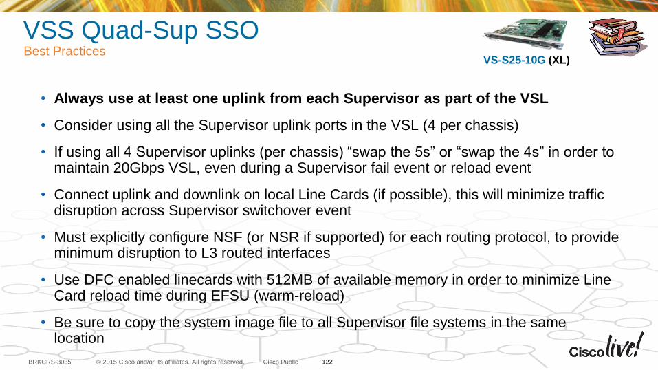
© 2015 Cisco and/or its affiliates. All rights reserved.BRKCRS-3035 Cisco Public
VSS Quad-Sup SSOBest Practices
• Always use at least one uplink from each Supervisor as part of the VSL
• Consider using all the Supervisor uplink ports in the VSL (4 per chassis)
• If using all 4 Supervisor uplinks (per chassis) “swap the 5s” or “swap the 4s” in order to maintain 20Gbps VSL, even during a Supervisor fail event or reload event
• Connect uplink and downlink on local Line Cards (if possible), this will minimize traffic disruption across Supervisor switchover event
• Must explicitly configure NSF (or NSR if supported) for each routing protocol, to provide minimum disruption to L3 routed interfaces
• Use DFC enabled linecards with 512MB of available memory in order to minimize Line Card reload time during EFSU (warm-reload)
• Be sure to copy the system image file to all Supervisor file systems in the same location
VS-S25-10G (XL)
122
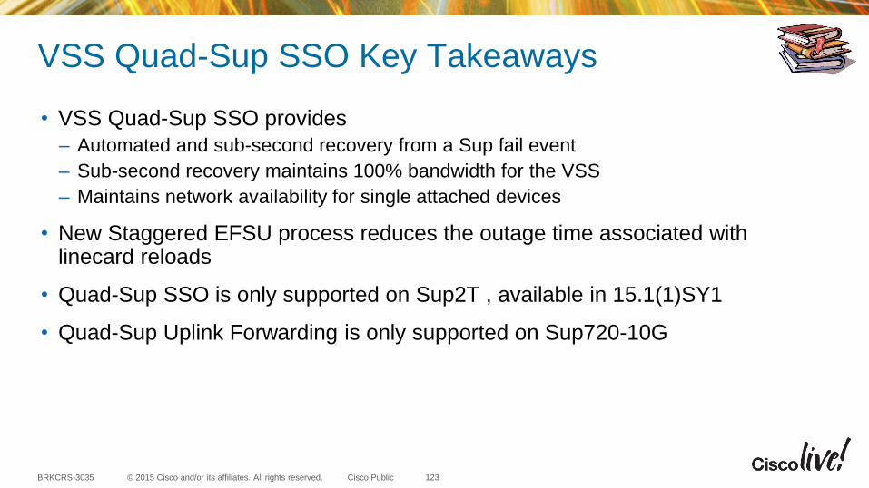
© 2015 Cisco and/or its affiliates. All rights reserved.BRKCRS-3035 Cisco Public
VSS Quad-Sup SSO Key Takeaways
• VSS Quad-Sup SSO provides
– Automated and sub-second recovery from a Sup fail event
– Sub-second recovery maintains 100% bandwidth for the VSS
– Maintains network availability for single attached devices
• New Staggered EFSU process reduces the outage time associated with linecard reloads
• Quad-Sup SSO is only supported on Sup2T , available in 15.1(1)SY1
• Quad-Sup Uplink Forwarding is only supported on Sup720-10G
123
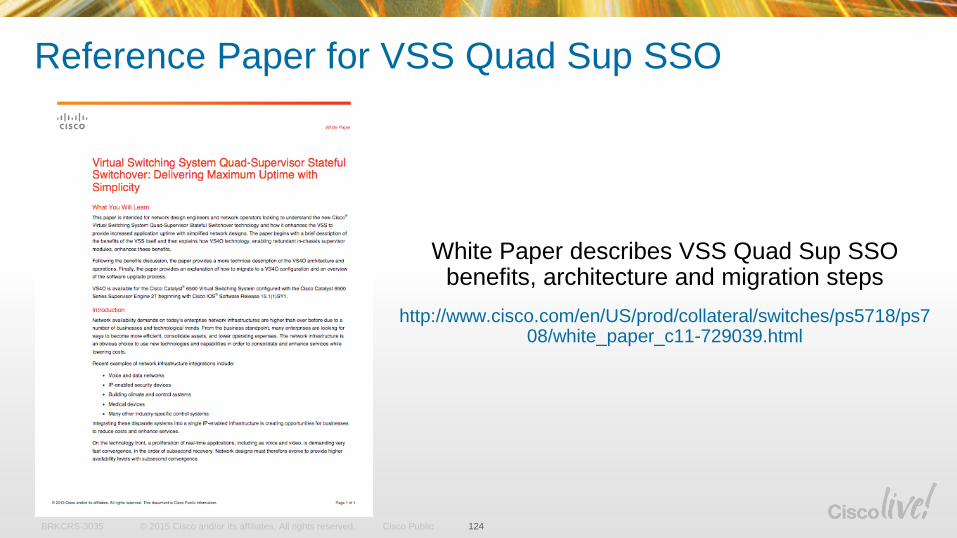
© 2015 Cisco and/or its affiliates. All rights reserved.BRKCRS-3035 Cisco Public
Reference Paper for VSS Quad Sup SSO
124
White Paper describes VSS Quad Sup SSO benefits, architecture and migration steps
http://www.cisco.com/en/US/prod/collateral/switches/ps5718/ps708/white_paper_c11-729039.html
VSL Design Considerations
12
5
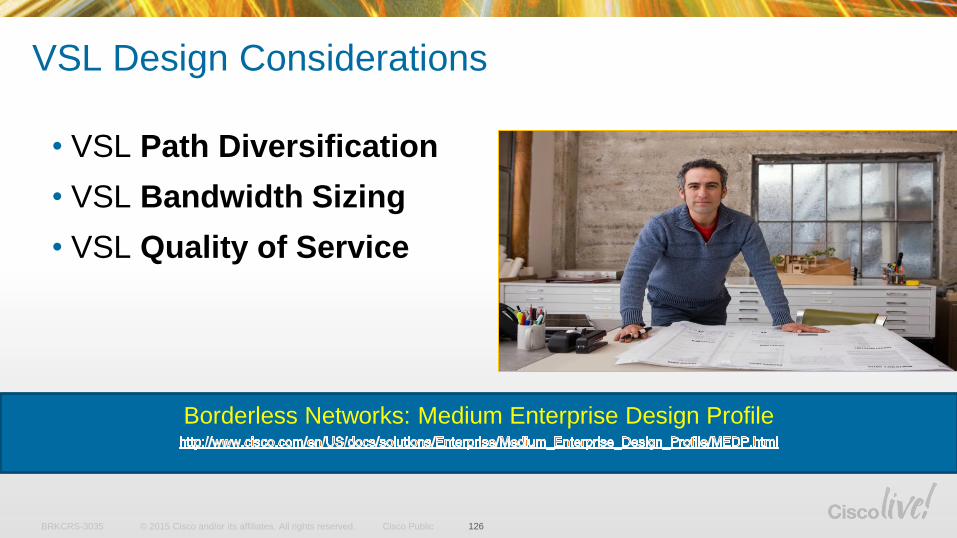
© 2015 Cisco and/or its affiliates. All rights reserved.BRKCRS-3035 Cisco Public
VSL Design Considerations
126
• VSL Path Diversification
• VSL Bandwidth Sizing
• VSL Quality of Service
Borderless Networks: Medium Enterprise Design Profile
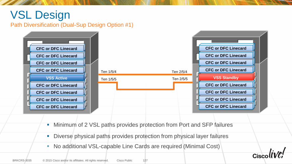
© 2015 Cisco and/or its affiliates. All rights reserved.BRKCRS-3035 Cisco Public
Minimum of 2 VSL paths provides protection from Port and SFP failures
Diverse physical paths provides protection from physical layer failures
No additional VSL-capable Line Cards are required (Minimal Cost)
127
CFC or DFC Linecard
CFC or DFC Linecard
CFC or DFC Linecard
CFC or DFC Linecard
VSS Active
CFC or DFC Linecard
CFC or DFC Linecard
CFC or DFC Linecard
CFC or DFC Linecard
CFC or DFC Linecard
CFC or DFC Linecard
CFC or DFC Linecard
CFC or DFC Linecard
VSS Standby
CFC or DFC Linecard
CFC or DFC Linecard
CFC or DFC Linecard
CFC or DFC Linecard
Ten 1/5/4 Ten 2/5/4
Ten 1/5/5 Ten 2/5/5
VSL DesignPath Diversification (Dual-Sup Design Option #1)
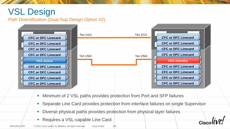
© 2015 Cisco and/or its affiliates. All rights reserved.BRKCRS-3035 Cisco Public
Minimum of 2 VSL paths provides protection from Port and SFP failures
Separate Line Card provides protection from interface failures on single Supervisor
Diverse physical paths provides protection from physical layer failures
Requires a VSL-capable Line Card
CFC or DFC Linecard
CFC or DFC Linecard
CFC or DFC Linecard
CFC or DFC Linecard
VSS Active
CFC or DFC Linecard
CFC or DFC Linecard
CFC or DFC Linecard
CFC or DFC Linecard
CFC or DFC Linecard
CFC or DFC Linecard
CFC or DFC Linecard
CFC or DFC Linecard
VSS Standby
CFC or DFC Linecard
CFC or DFC Linecard
CFC or DFC Linecard
CFC or DFC Linecard
Ten 1/5/4 Ten 2/5/4
Ten 1/1/1 Ten 2/1/1
VSL DesignPath Diversification (Dual-Sup Design Option #2)
128
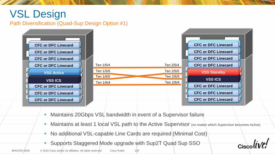
© 2015 Cisco and/or its affiliates. All rights reserved.BRKCRS-3035 Cisco Public
CFC or DFC Linecard
CFC or DFC Linecard
CFC or DFC Linecard
VSS ICS
VSS Standby
CFC or DFC Linecard
CFC or DFC Linecard
CFC or DFC Linecard
CFC or DFC Linecard
Maintains 20Gbps VSL bandwidth in event of a Supervisor failure
Maintains at least 1 local VSL path to the Active Supervisor (no matter which Supervisor becomes Active)
No additional VSL-capable Line Cards are required (Minimal Cost)
Supports Staggered Mode upgrade with Sup2T Quad Sup SSO
129
CFC or DFC Linecard
CFC or DFC Linecard
CFC or DFC Linecard
VSS ICS
VSS Active
CFC or DFC Linecard
CFC or DFC Linecard
CFC or DFC Linecard
CFC or DFC Linecard
Ten 2/5/5
Ten 2/6/5
Ten 1/5/5
Ten 1/6/5
Ten 1/5/4 Ten 2/5/4
Ten 1/6/4 Ten 2/6/4
VSL DesignPath Diversification (Quad-Sup Design Option #1)
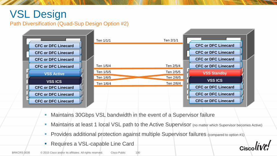
© 2015 Cisco and/or its affiliates. All rights reserved.BRKCRS-3035 Cisco Public
CFC or DFC Linecard
CFC or DFC Linecard
CFC or DFC Linecard
VSS ICS
VSS Standby
CFC or DFC Linecard
CFC or DFC Linecard
CFC or DFC Linecard
CFC or DFC Linecard
130
CFC or DFC Linecard
CFC or DFC Linecard
CFC or DFC Linecard
VSS ICS
VSS Active
CFC or DFC Linecard
CFC or DFC Linecard
CFC or DFC Linecard
CFC or DFC Linecard
Ten 2/5/5
Ten 2/6/5
Ten 1/5/5
Ten 1/6/5
Ten 1/5/4 Ten 2/5/4
Ten 1/6/4 Ten 2/6/4
VSL DesignPath Diversification (Quad-Sup Design Option #2)
Maintains 30Gbps VSL bandwidth in the event of a Supervisor failure
Maintains at least 1 local VSL path to the Active Supervisor (no matter which Supervisor becomes Active)
Provides additional protection against multiple Supervisor failures (compared to option #1)
Requires a VSL-capable Line Card
Ten 1/1/1 Ten 2/1/1

© 2015 Cisco and/or its affiliates. All rights reserved.BRKCRS-3035 Cisco Public
Virtual Switch Link interfaces are restricted from QoS policy changes
- Class of Service based queuing is automatically added to the VSL port channel interfaces on Sup720-10G, this is not applicable on systems (trust cos)
- Default CoS to Queue mapping is enforced
- Interface Maximum Transmission Unit (MTU) size is automatically set to 9216 bytes
Critical control traffic is automatically marked and receives priority queuing
- Control traffic is set with CoS=5 BPDU=1
- Marked in VSL Header (VSH)
Virtual Switch Link Built In QoS
interface Port-channel1
no switchport
no ip address
switch virtual link 1
mls qos trust cos
no mls qos channel-consistency
Q3Q2Q1
Sup720-10G Example
131
Pri
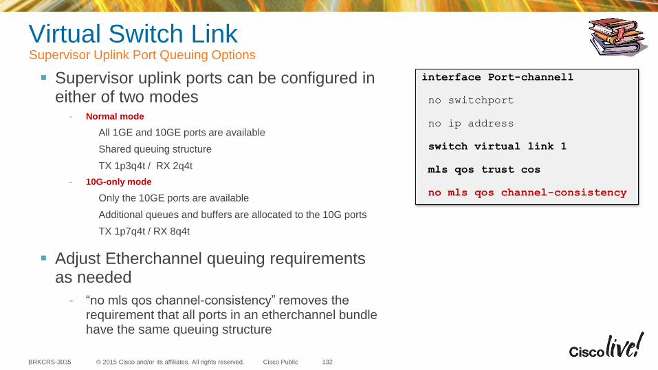
© 2015 Cisco and/or its affiliates. All rights reserved.BRKCRS-3035 Cisco Public
Supervisor uplink ports can be configured in either of two modes
- Normal mode
All 1GE and 10GE ports are available
Shared queuing structure
TX 1p3q4t / RX 2q4t
- 10G-only mode
Only the 10GE ports are available
Additional queues and buffers are allocated to the 10G ports
TX 1p7q4t / RX 8q4t
Adjust Etherchannel queuing requirements as needed
- “no mls qos channel-consistency” removes the requirement that all ports in an etherchannel bundle have the same queuing structure
Virtual Switch LinkSupervisor Uplink Port Queuing Options
interface Port-channel1
no switchport
no ip address
switch virtual link 1
mls qos trust cos
no mls qos channel-consistency
132
VSS In-Service Software Upgrades
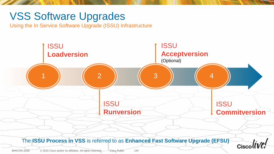
© 2015 Cisco and/or its affiliates. All rights reserved.BRKCRS-3035 Cisco Public
VSS Software UpgradesUsing the In Service Software Upgrade (ISSU) Infrastructure
134
The ISSU Process in VSS is referred to as Enhanced Fast Software Upgrade (EFSU)
1
ISSU
Loadversion
3
ISSU
Acceptversion(Optional)
2
ISSU
Runversion
4
ISSU
Commitversion
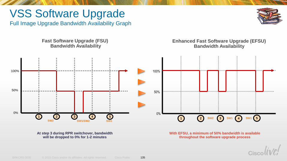
© 2015 Cisco and/or its affiliates. All rights reserved.BRKCRS-3035 Cisco Public
VSS Software Upgrade Full Image Upgrade Bandwidth Availability Graph
1 2 3
100%
50%
4 5
0%
100%
50%
0%
1 2 3 4 5
Fast Software Upgrade (FSU)Bandwidth Availability
Enhanced Fast Software Upgrade (EFSU) Bandwidth Availability
With EFSU, a minimum of 50% bandwidth is available throughout the software upgrade process
At step 3 during RPR switchover, bandwidth will be dropped to 0% for 1-2 minutes
SW2 SW1 SW1SW2 SW1/SW2 SW1
135
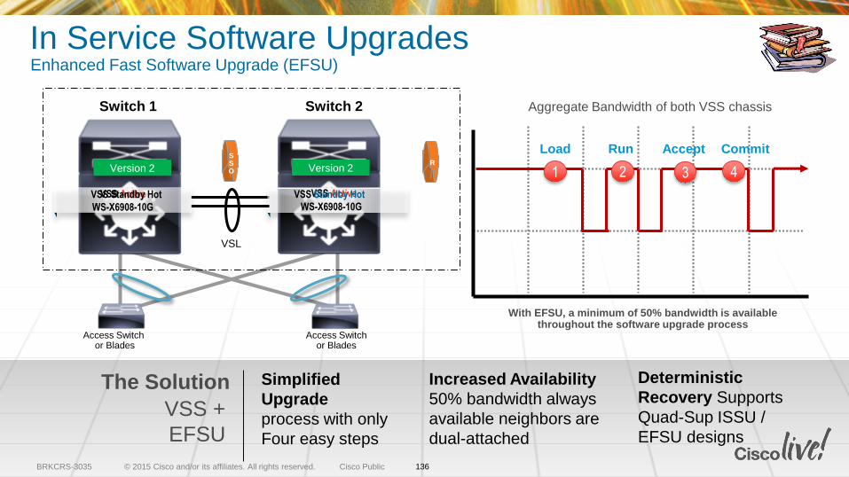
© 2015 Cisco and/or its affiliates. All rights reserved.BRKCRS-3035 Cisco Public
In Service Software UpgradesEnhanced Fast Software Upgrade (EFSU)
Switch 1 Switch 2
The Solution
VSS +
EFSU
Increased Availability
50% bandwidth always
available neighbors are
dual-attached
Simplified
Upgrade
process with only
Four easy steps
Deterministic
Recovery Supports
Quad-Sup ISSU /
EFSU designs
VSS ActiveVSS Standby HotWS-X6908-10G
R
With EFSU, a minimum of 50% bandwidth is available throughout the software upgrade process
Aggregate Bandwidth of both VSS chassis
Load Run Accept CommitSSO
VSL
VSS Active
WS-X6908-10G
VSS Standby Hot
Access Switchor Blades
Access Switch or Blades
Version 1 Version 2 Version 1 Version 2
136
1 2 43
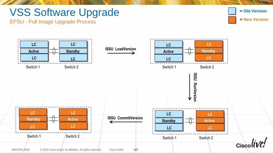
© 2015 Cisco and/or its affiliates. All rights reserved.BRKCRS-3035 Cisco Public
VSS Software Upgrade EFSU - Full Image Upgrade Process
ISSU LoadVersion
ISS
U R
un
Versio
n
ISSU CommitVersion
Switch 1 Switch 2
StandbyActive
LC
LCLC
LC
Switch 1 Switch 2
Active
LC
LC
Standby
LC
LC
= Old Version
= New Version
Switch 1 Switch 2
Standby Active
LC
LC
LC
LC
Switch 1 Switch 2
Standby
LC
LC
Active
LC
LC
137
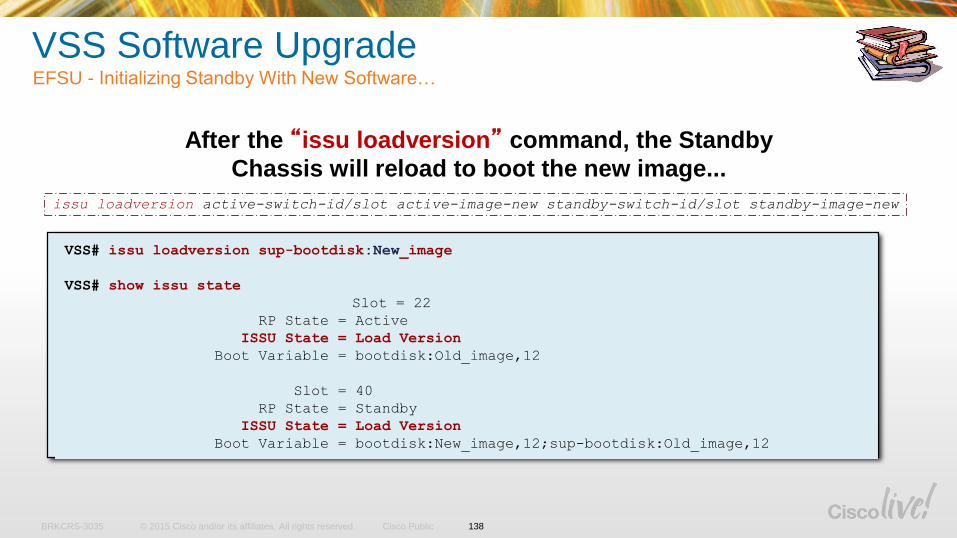
© 2015 Cisco and/or its affiliates. All rights reserved.BRKCRS-3035 Cisco Public
VSS Software Upgrade EFSU - Initializing Standby With New Software…
After the “issu loadversion” command, the Standby
Chassis will reload to boot the new image...
VSS# issu loadversion sup-bootdisk:New_image
VSS# show issu state
Slot = 22
RP State = Active
ISSU State = Load Version
Boot Variable = bootdisk:Old_image,12
Slot = 40
RP State = Standby
ISSU State = Load Version
Boot Variable = bootdisk:New_image,12;sup-bootdisk:Old_image,12
issu loadversion active-switch-id/slot active-image-new standby-switch-id/slot standby-image-new
138
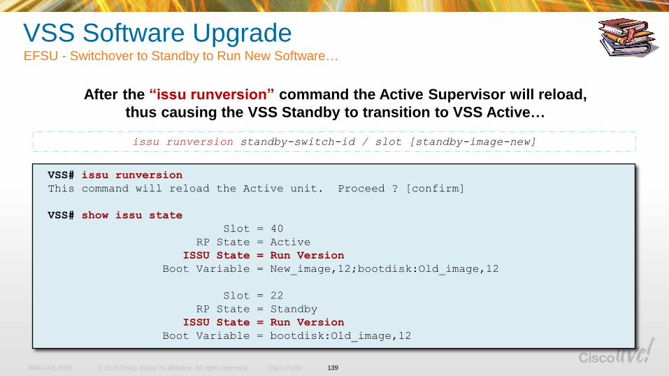
© 2015 Cisco and/or its affiliates. All rights reserved.BRKCRS-3035 Cisco Public
After the “issu runversion” command the Active Supervisor will reload,
thus causing the VSS Standby to transition to VSS Active…
VSS# issu runversion
This command will reload the Active unit. Proceed ? [confirm]
VSS# show issu state
Slot = 40
RP State = Active
ISSU State = Run Version
Boot Variable = New_image,12;bootdisk:Old_image,12
Slot = 22
RP State = Standby
ISSU State = Run Version
Boot Variable = bootdisk:Old_image,12
issu runversion standby-switch-id / slot [standby-image-new]
VSS Software Upgrade EFSU - Switchover to Standby to Run New Software…
139
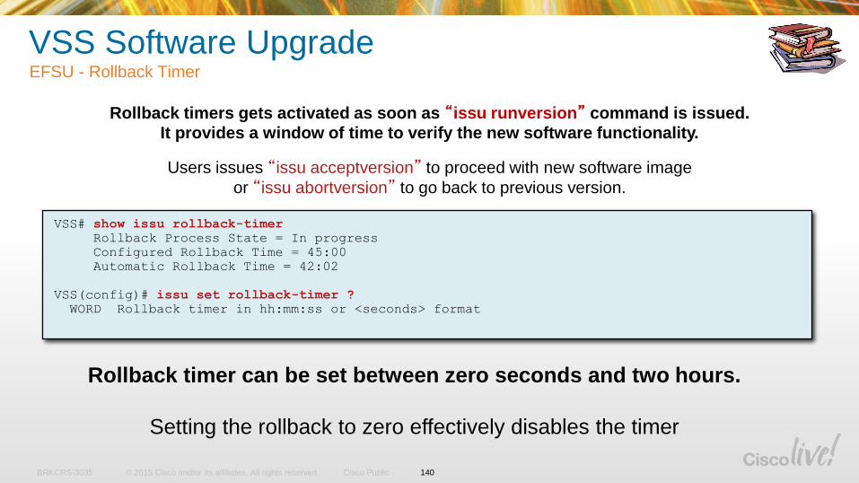
© 2015 Cisco and/or its affiliates. All rights reserved.BRKCRS-3035 Cisco Public
VSS Software Upgrade EFSU - Rollback Timer
VSS# show issu rollback-timer
Rollback Process State = In progress
Configured Rollback Time = 45:00
Automatic Rollback Time = 42:02
VSS(config)# issu set rollback-timer ?
WORD Rollback timer in hh:mm:ss or <seconds> format
Rollback timers gets activated as soon as “issu runversion” command is issued.
It provides a window of time to verify the new software functionality.
Users issues “issu acceptversion” to proceed with new software image
or “issu abortversion” to go back to previous version.
Rollback timer can be set between zero seconds and two hours.
Setting the rollback to zero effectively disables the timer
140
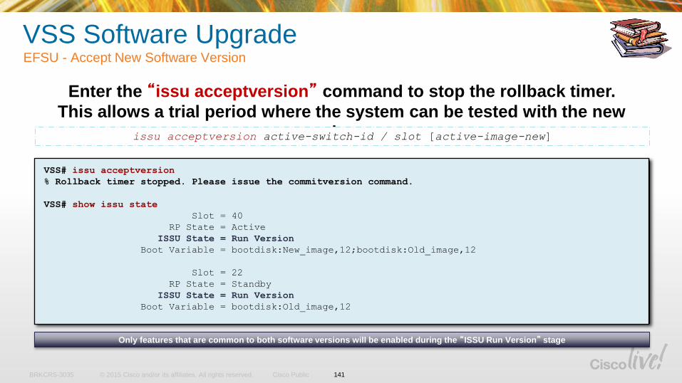
© 2015 Cisco and/or its affiliates. All rights reserved.BRKCRS-3035 Cisco Public
VSS Software Upgrade EFSU - Accept New Software Version
Enter the “issu acceptversion” command to stop the rollback timer.
This allows a trial period where the system can be tested with the new
image.
VSS# issu acceptversion
% Rollback timer stopped. Please issue the commitversion command.
VSS# show issu state
Slot = 40
RP State = Active
ISSU State = Run Version
Boot Variable = bootdisk:New_image,12;bootdisk:Old_image,12
Slot = 22
RP State = Standby
ISSU State = Run Version
Boot Variable = bootdisk:Old_image,12
issu acceptversion active-switch-id / slot [active-image-new]
Only features that are common to both software versions will be enabled during the “ISSU Run Version” stage
141
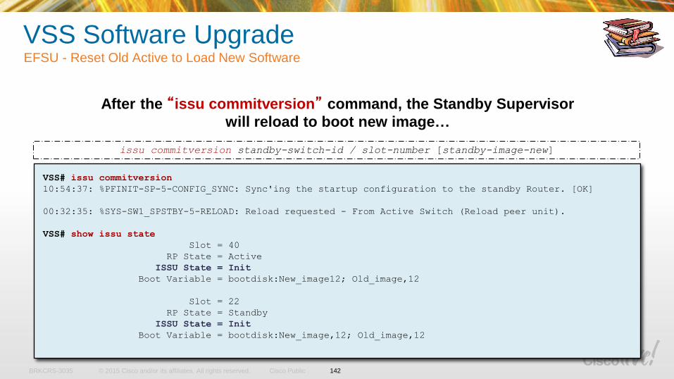
© 2015 Cisco and/or its affiliates. All rights reserved.BRKCRS-3035 Cisco Public
VSS Software Upgrade EFSU - Reset Old Active to Load New Software
After the “issu commitversion” command, the Standby Supervisor
will reload to boot new image…
VSS# issu commitversion
10:54:37: %PFINIT-SP-5-CONFIG_SYNC: Sync'ing the startup configuration to the standby Router. [OK]
00:32:35: %SYS-SW1_SPSTBY-5-RELOAD: Reload requested - From Active Switch (Reload peer unit).
VSS# show issu state
Slot = 40
RP State = Active
ISSU State = Init
Boot Variable = bootdisk:New_image12; Old_image,12
Slot = 22
RP State = Standby
ISSU State = Init
Boot Variable = bootdisk:New_image,12; Old_image,12
issu commitversion standby-switch-id / slot-number [standby-image-new]
142
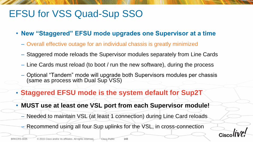
© 2015 Cisco and/or its affiliates. All rights reserved.BRKCRS-3035 Cisco Public
EFSU for VSS Quad-Sup SSO
• New “Staggered” EFSU mode upgrades one Supervisor at a time
– Overall effective outage for an individual chassis is greatly minimized
– Staggered mode reloads the Supervisor modules separately from Line Cards
– Line Cards must reload (to boot / run the new software), during the process
– Optional “Tandem” mode will upgrade both Supervisors modules per chassis (same as process with Dual Sup VSS)
• Staggered EFSU mode is the system default for Sup2T
• MUST use at least one VSL port from each Supervisor module!
– Needed to maintain VSL (at least 1 connection) during Line Card reloads
– Recommend using all four Sup uplinks for the VSL, in cross-connection
143
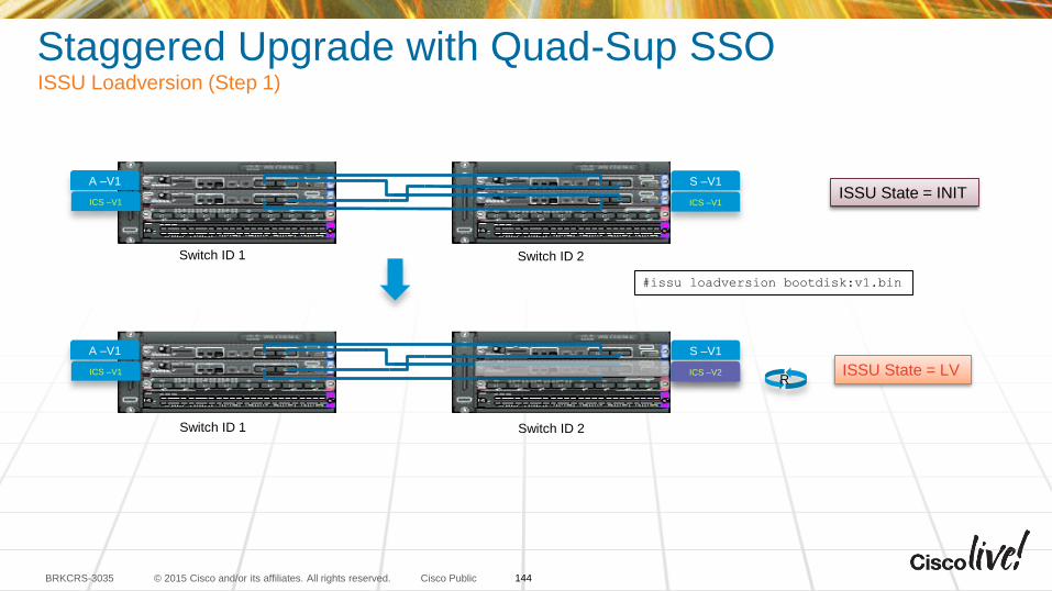
© 2015 Cisco and/or its affiliates. All rights reserved.BRKCRS-3035 Cisco Public
Staggered Upgrade with Quad-Sup SSOISSU Loadversion (Step 1)
A –V1
ICS –V1
S –V1
ICS –V1
R
#issu loadversion bootdisk:v1.bin
ISSU State = INIT
ISSU State = LV
Switch ID 1 Switch ID 2
ICS –V1
A –V1
ICS –V1
S –V1
Switch ID 1 Switch ID 2
ICS –V2
144
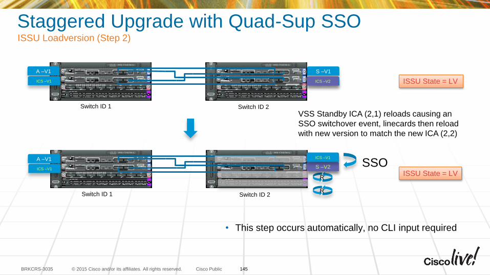
© 2015 Cisco and/or its affiliates. All rights reserved.BRKCRS-3035 Cisco Public
Staggered Upgrade with Quad-Sup SSOISSU Loadversion (Step 2)
• This step occurs automatically, no CLI input required
A –V1
ICS –V1
S –V1
ICS –V1
R
ICS –V2
ISSU State = LV
ISSU State = LV
R
Switch ID 1 Switch ID 2
A –V1
ICS –V1
S –V1
ICS –V2
Switch ID 1 Switch ID 2
VSS Standby ICA (2,1) reloads causing an
SSO switchover event, linecards then reload
with new version to match the new ICA (2,2)
SSOS –V2
ICS –V1
145
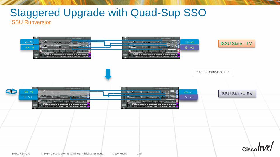
© 2015 Cisco and/or its affiliates. All rights reserved.BRKCRS-3035 Cisco Public
Staggered Upgrade with Quad-Sup SSOISSU Runversion
A –V1
ICS –V1
S –V1
ICS –V1
R
ISSU State = LVICS –V1
S –V2
#issu runversion
A –V1
ICS –V1
S –V1
ICS –V1
ICS –V1
S –V2S –V1
ICS –V1ISSU State = RV
A –V2
146
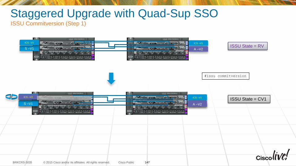
© 2015 Cisco and/or its affiliates. All rights reserved.BRKCRS-3035 Cisco Public
Staggered Upgrade with Quad-Sup SSOISSU Commitversion (Step 1)
R
ISSU State = RV
#issu commitversion
ISSU State = CV1A –V1
ICS –V1
S –V1
ICS –V1
ICS –V1
S –V2S –V1
ICS –V1
A –V2
ICS –V2
ICS –V1
S –V1
ICS –V1
A –V2
147
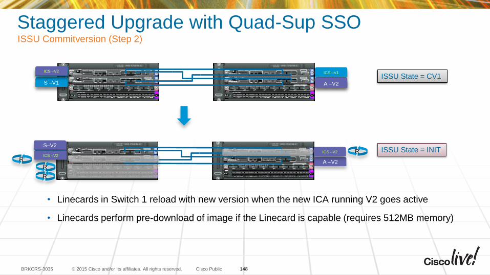
© 2015 Cisco and/or its affiliates. All rights reserved.BRKCRS-3035 Cisco Public
Staggered Upgrade with Quad-Sup SSOISSU Commitversion (Step 2)
• Linecards in Switch 1 reload with new version when the new ICA running V2 goes active
• Linecards perform pre-download of image if the Linecard is capable (requires 512MB memory)
R
ISSU State = CV1
ISSU State = INITICS –V1S –V1
A –V2
ICS –V2
A –V1
ICS –V1
S –V1
ICS –V1
ICS –V1
S –V2S –V1
ICS –V1
A –V2
ICS –V2
RICS –V2
S–V2
ICS –V2
R
R
148
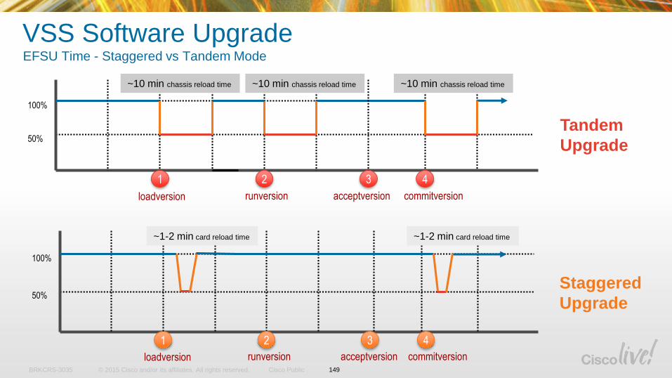
© 2015 Cisco and/or its affiliates. All rights reserved.BRKCRS-3035 Cisco Public
VSS Software UpgradeEFSU Time - Staggered vs Tandem Mode
1 2 3 4
100%
50%
loadversion runversion acceptversion commitversion
~10 min chassis reload time ~10 min chassis reload time ~10 min chassis reload time
1 2 3 4
100%
50%
loadversion runversion acceptversion commitversion
~1-2 min card reload time ~1-2 min card reload time
Tandem
Upgrade
Staggered
Upgrade
149
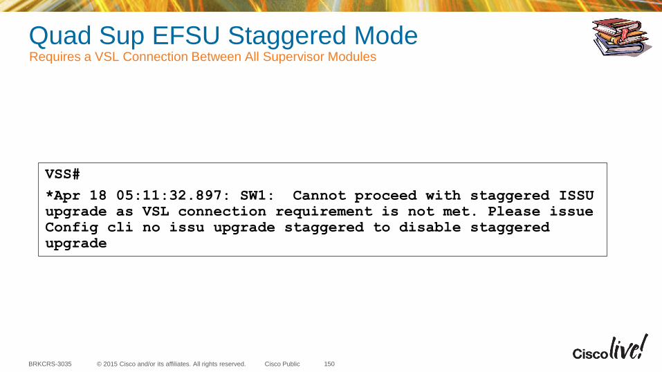
© 2015 Cisco and/or its affiliates. All rights reserved.BRKCRS-3035 Cisco Public
Quad Sup EFSU Staggered Mode Requires a VSL Connection Between All Supervisor Modules
150
VSS#
*Apr 18 05:11:32.897: SW1: Cannot proceed with staggered ISSU
upgrade as VSL connection requirement is not met. Please issue
Config cli no issu upgrade staggered to disable staggered
upgrade
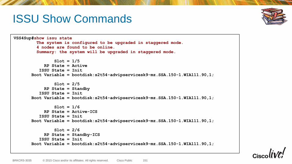
© 2015 Cisco and/or its affiliates. All rights reserved.BRKCRS-3035 Cisco Public
ISSU Show Commands
VSS4Sup#show issu state
The system is configured to be upgraded in staggered mode.
4 nodes are found to be online.
Summary: the system will be upgraded in staggered mode.
Slot = 1/5
RP State = Active
ISSU State = Init
Boot Variable = bootdisk:s2t54-advipservicesk9-mz.SSA.150-1.WIA111.90,1;
Slot = 2/5
RP State = Standby
ISSU State = Init
Boot Variable = bootdisk:s2t54-advipservicesk9-mz.SSA.150-1.WIA111.90,1;
Slot = 1/6
RP State = Active-ICS
ISSU State = Init
Boot Variable = bootdisk:s2t54-advipservicesk9-mz.SSA.150-1.WIA111.90,1;
Slot = 2/6
RP State = Standby-ICS
ISSU State = Init
Boot Variable = bootdisk:s2t54-advipservicesk9-mz.SSA.150-1.WIA111.90,1;
151
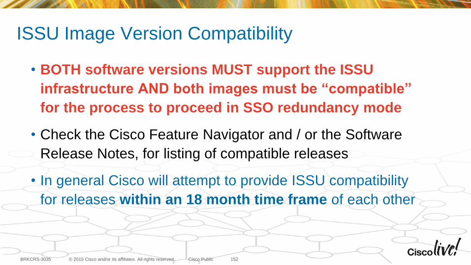
© 2015 Cisco and/or its affiliates. All rights reserved.BRKCRS-3035 Cisco Public
ISSU Image Version Compatibility
152
• BOTH software versions MUST support the ISSU
infrastructure AND both images must be “compatible”
for the process to proceed in SSO redundancy mode
• Check the Cisco Feature Navigator and / or the Software
Release Notes, for listing of compatible releases
• In general Cisco will attempt to provide ISSU compatibility
for releases within an 18 month time frame of each other
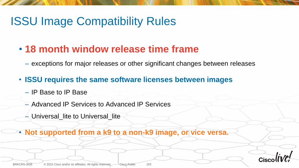
© 2015 Cisco and/or its affiliates. All rights reserved.BRKCRS-3035 Cisco Public
ISSU Image Compatibility Rules
153
• 18 month window release time frame
– exceptions for major releases or other significant changes between releases
• ISSU requires the same software licenses between images
– IP Base to IP Base
– Advanced IP Services to Advanced IP Services
– Universal_lite to Universal_lite
• Not supported from a k9 to a non-k9 image, or vice versa.
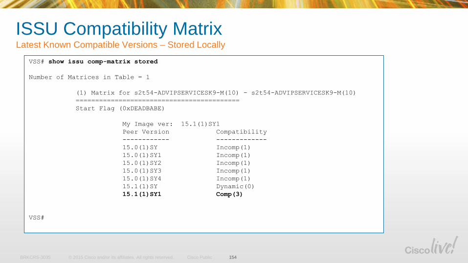
© 2015 Cisco and/or its affiliates. All rights reserved.BRKCRS-3035 Cisco Public
ISSU Compatibility Matrix Latest Known Compatible Versions – Stored Locally
154
VSS# show issu comp-matrix stored
Number of Matrices in Table = 1
(1) Matrix for s2t54-ADVIPSERVICESK9-M(10) - s2t54-ADVIPSERVICESK9-M(10)
==========================================
Start Flag (0xDEADBABE)
My Image ver: 15.1(1)SY1
Peer Version Compatibility
------------ -------------
15.0(1)SY Incomp(1)
15.0(1)SY1 Incomp(1)
15.0(1)SY2 Incomp(1)
15.0(1)SY3 Incomp(1)
15.0(1)SY4 Incomp(1)
15.1(1)SY Dynamic(0)
15.1(1)SY1 Comp(3)
VSS#
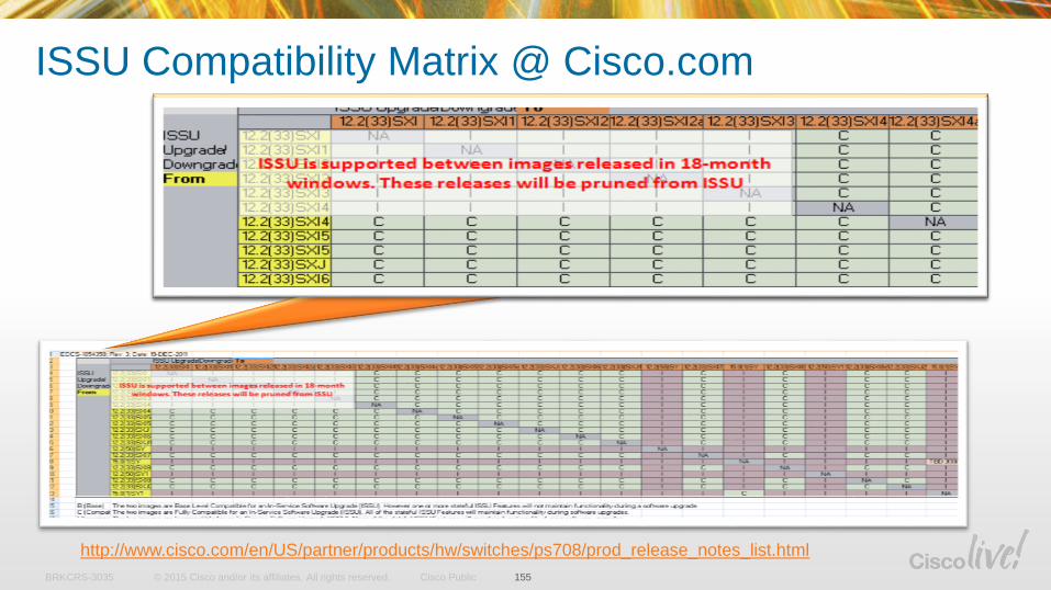
© 2015 Cisco and/or its affiliates. All rights reserved.BRKCRS-3035 Cisco Public
http://www.cisco.com/en/US/partner/products/hw/switches/ps708/prod_release_notes_list.html
ISSU Compatibility Matrix @ Cisco.com
155
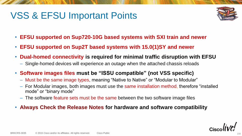
© 2015 Cisco and/or its affiliates. All rights reserved.BRKCRS-3035 Cisco Public
VSS & EFSU Important Points
• EFSU supported on Sup720-10G based systems with SXI train and newer
• EFSU supported on Sup2T based systems with 15.0(1)SY and newer
• Dual-homed connectivity is required for minimal traffic disruption with EFSU
– Single-homed devices will experience an outage when the attached chassis reloads
• Software images files must be “ISSU compatible” (not VSS specific)
– Must be the same image types, meaning “Native to Native” or “Modular to Modular”
– For Modular images, both images must use the same installation method, therefore “installed mode” or “binary mode”
– The software feature sets must be the same between the two software image files
• Always Check the Release Notes for hardware and software compatibility
156
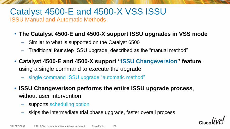
© 2015 Cisco and/or its affiliates. All rights reserved.BRKCRS-3035 Cisco Public
Catalyst 4500-E and 4500-X VSS ISSUISSU Manual and Automatic Methods
157
• The Catalyst 4500-E and 4500-X support ISSU upgrades in VSS mode
– Similar to what is supported on the Catalyst 6500
– Traditional four step ISSU upgrade, described as the “manual method”
• Catalyst 4500-E and 4500-X support “ISSU Changeversion” feature,
using a single command to execute the upgrade
– single command ISSU upgrade “automatic method”
• ISSU Changeverison performs the entire ISSU upgrade process,
without user intervention
– supports scheduling option
– skips the intermediate trial phase upgrade, faster overall process
Deployment Considerations and Best Practices
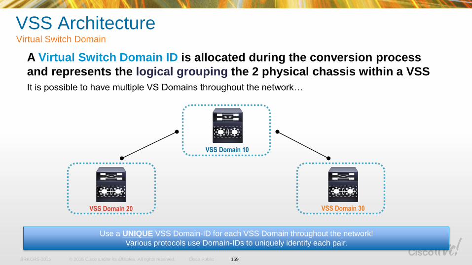
© 2015 Cisco and/or its affiliates. All rights reserved.BRKCRS-3035 Cisco Public
VSS ArchitectureVirtual Switch Domain
A Virtual Switch Domain ID is allocated during the conversion process
and represents the logical grouping the 2 physical chassis within a VSS
It is possible to have multiple VS Domains throughout the network…
Use a UNIQUE VSS Domain-ID for each VSS Domain throughout the network!
Various protocols use Domain-IDs to uniquely identify each pair.
VSS Domain 10
VSS Domain 20 VSS Domain 30
159
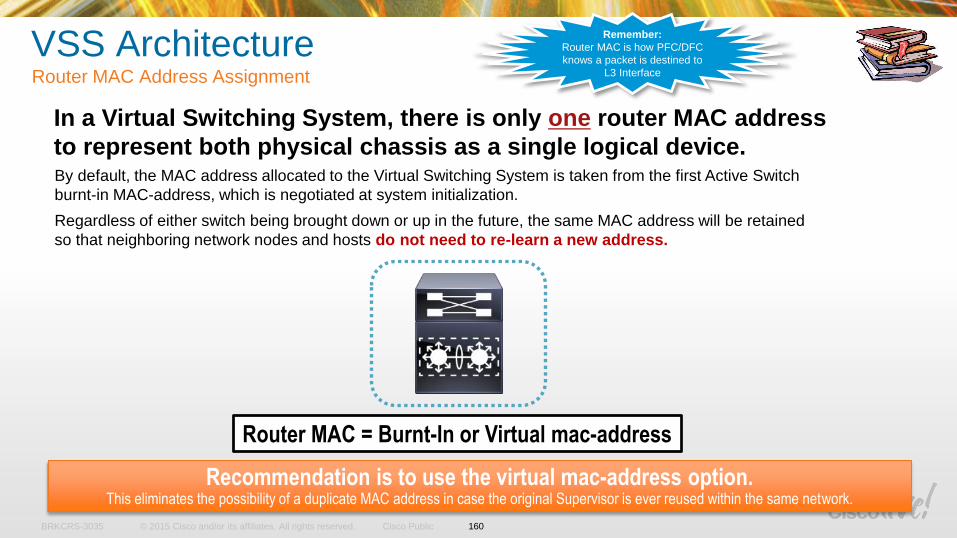
© 2015 Cisco and/or its affiliates. All rights reserved.BRKCRS-3035 Cisco Public
VSS ArchitectureRouter MAC Address Assignment
In a Virtual Switching System, there is only one router MAC address
to represent both physical chassis as a single logical device.
Router MAC = Burnt-In or Virtual mac-address
By default, the MAC address allocated to the Virtual Switching System is taken from the first Active Switch
burnt-in MAC-address, which is negotiated at system initialization.
Regardless of either switch being brought down or up in the future, the same MAC address will be retained
so that neighboring network nodes and hosts do not need to re-learn a new address.
Recommendation is to use the virtual mac-address option. This eliminates the possibility of a duplicate MAC address in case the original Supervisor is ever reused within the same network.
Remember:
Router MAC is how PFC/DFC
knows a packet is destined to
L3 Interface
160
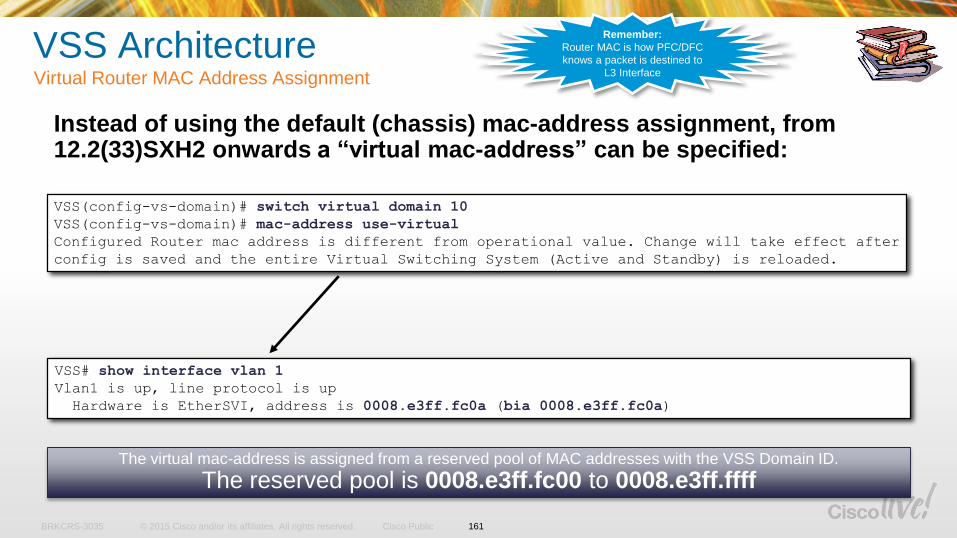
© 2015 Cisco and/or its affiliates. All rights reserved.BRKCRS-3035 Cisco Public
VSS ArchitectureVirtual Router MAC Address Assignment
Instead of using the default (chassis) mac-address assignment, from 12.2(33)SXH2 onwards a “virtual mac-address” can be specified:
VSS(config-vs-domain)# switch virtual domain 10
VSS(config-vs-domain)# mac-address use-virtual
Configured Router mac address is different from operational value. Change will take effect after
config is saved and the entire Virtual Switching System (Active and Standby) is reloaded.
The virtual mac-address is assigned from a reserved pool of MAC addresses with the VSS Domain ID.
The reserved pool is 0008.e3ff.fc00 to 0008.e3ff.ffff
VSS# show interface vlan 1
Vlan1 is up, line protocol is up
Hardware is EtherSVI, address is 0008.e3ff.fc0a (bia 0008.e3ff.fc0a)
161
Remember:
Router MAC is how PFC/DFC
knows a packet is destined to
L3 Interface
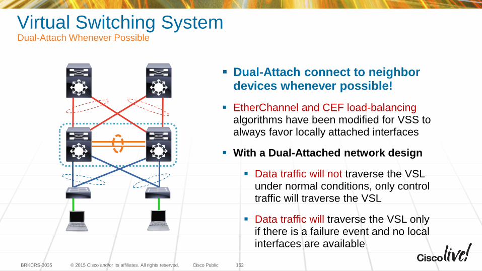
© 2015 Cisco and/or its affiliates. All rights reserved.BRKCRS-3035 Cisco Public
Virtual Switching SystemDual-Attach Whenever Possible
162
Dual-Attach connect to neighbor devices whenever possible!
EtherChannel and CEF load-balancing algorithms have been modified for VSS to always favor locally attached interfaces
With a Dual-Attached network design
Data traffic will not traverse the VSL under normal conditions, only control traffic will traverse the VSL
Data traffic will traverse the VSL only if there is a failure event and no local interfaces are available
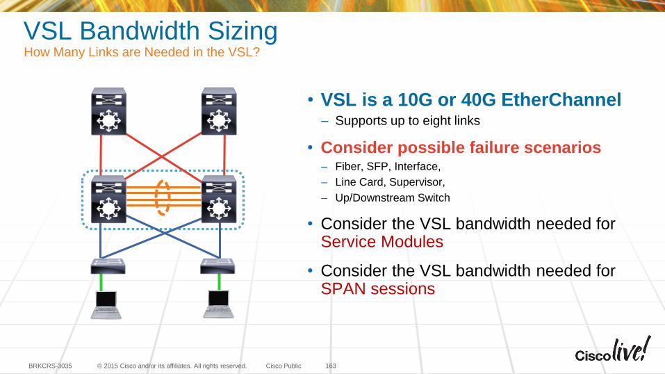
© 2015 Cisco and/or its affiliates. All rights reserved.BRKCRS-3035 Cisco Public
VSL Bandwidth SizingHow Many Links are Needed in the VSL?
163
• VSL is a 10G or 40G EtherChannel– Supports up to eight links
• Consider possible failure scenarios– Fiber, SFP, Interface,
– Line Card, Supervisor,
– Up/Downstream Switch
• Consider the VSL bandwidth needed for Service Modules
• Consider the VSL bandwidth needed for SPAN sessions
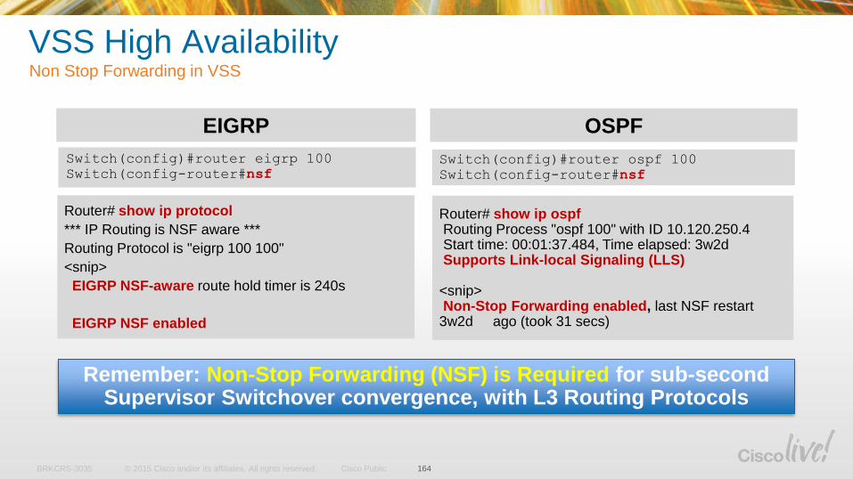
© 2015 Cisco and/or its affiliates. All rights reserved.BRKCRS-3035 Cisco Public
VSS High AvailabilityNon Stop Forwarding in VSS
164
Router# show ip ospfRouting Process "ospf 100" with ID 10.120.250.4Start time: 00:01:37.484, Time elapsed: 3w2dSupports Link-local Signaling (LLS)
<snip>Non-Stop Forwarding enabled, last NSF restart
3w2d ago (took 31 secs)
Router# show ip protocol
*** IP Routing is NSF aware ***
Routing Protocol is "eigrp 100 100"
<snip>
EIGRP NSF-aware route hold timer is 240s
EIGRP NSF enabled
Remember: Non-Stop Forwarding (NSF) is Required for sub-second Supervisor Switchover convergence, with L3 Routing Protocols
EIGRP OSPF
Switch(config)#router ospf 100
Switch(config-router#nsf
Switch(config)#router eigrp 100
Switch(config-router#nsf
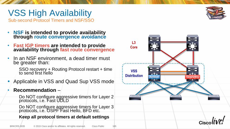
© 2015 Cisco and/or its affiliates. All rights reserved.BRKCRS-3035 Cisco Public
• NSF is intended to provide availability through route convergence avoidance
• Fast IGP timers are intended to provide availability through fast route convergence
• In an NSF environment, a dead timer must be greater than:
SSO recovery + Routing Protocol restart + time to send first hello
Applicable in VSS and Quad Sup VSS mode
• Recommendation –
Do NOT configure aggressive timers for Layer 2 protocols, i.e. Fast UDLD
Do NOT configure aggressive timers for Layer 3 protocols, i.e. OSPF Fast Hello, BFD etc.
Keep all protocol timers at default settings
VSS High AvailabilitySub-second Protocol Timers and NSF/SSO
165
VSS
Distribution
L3
Core
Active Standby
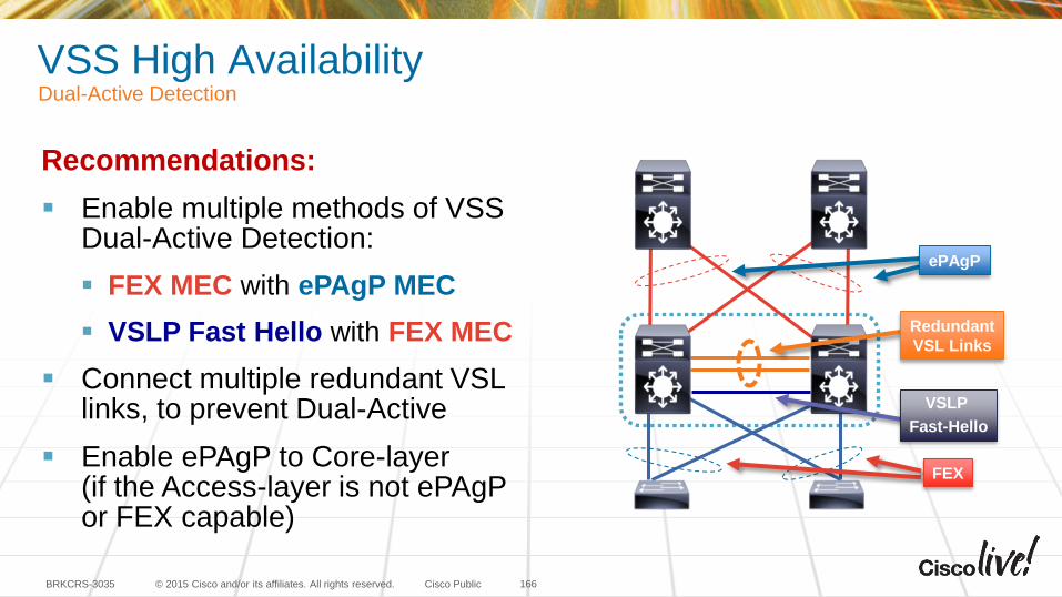
© 2015 Cisco and/or its affiliates. All rights reserved.BRKCRS-3035 Cisco Public
VSS High AvailabilityDual-Active Detection
166
VSLP
Fast-Hello
Redundant
VSL Links
ePAgP
FEX
Recommendations:
Enable multiple methods of VSS Dual-Active Detection:
FEX MEC with ePAgP MEC
VSLP Fast Hello with FEX MEC
Connect multiple redundant VSL links, to prevent Dual-Active
Enable ePAgP to Core-layer (if the Access-layer is not ePAgPor FEX capable)
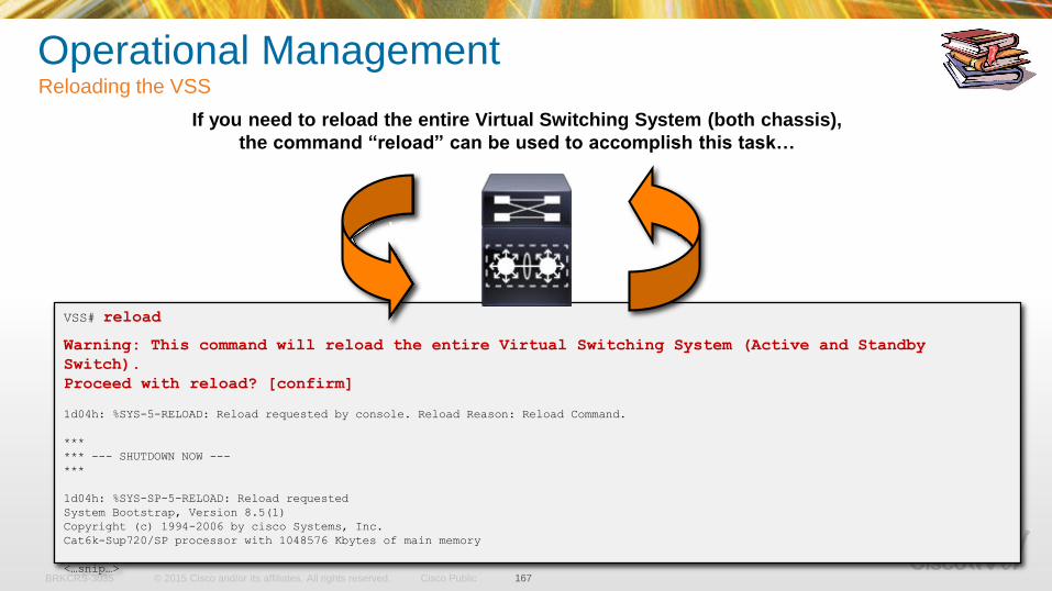
© 2015 Cisco and/or its affiliates. All rights reserved.BRKCRS-3035 Cisco Public
Operational ManagementReloading the VSS
167
If you need to reload the entire Virtual Switching System (both chassis),
the command “reload” can be used to accomplish this task…
VSS# reload
Warning: This command will reload the entire Virtual Switching System (Active and Standby
Switch).
Proceed with reload? [confirm]
1d04h: %SYS-5-RELOAD: Reload requested by console. Reload Reason: Reload Command.
***
*** --- SHUTDOWN NOW ---
***
1d04h: %SYS-SP-5-RELOAD: Reload requested
System Bootstrap, Version 8.5(1)
Copyright (c) 1994-2006 by cisco Systems, Inc.
Cat6k-Sup720/SP processor with 1048576 Kbytes of main memory
<…snip…>
Virtual Switch
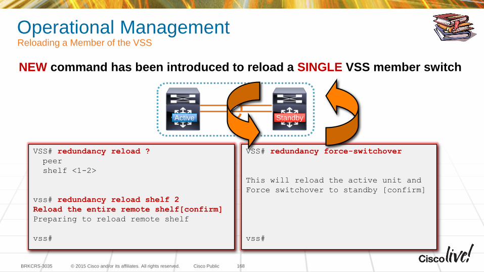
© 2015 Cisco and/or its affiliates. All rights reserved.BRKCRS-3035 Cisco Public
Operational ManagementReloading a Member of the VSS
168
VSS# redundancy reload ?
peer
shelf <1-2>
vss# redundancy reload shelf 2
Reload the entire remote shelf[confirm]
Preparing to reload remote shelf
vss#
VSS# redundancy force-switchover
This will reload the active unit and
Force switchover to standby [confirm]
vss#
NEW command has been introduced to reload a SINGLE VSS member switch
Active Standby
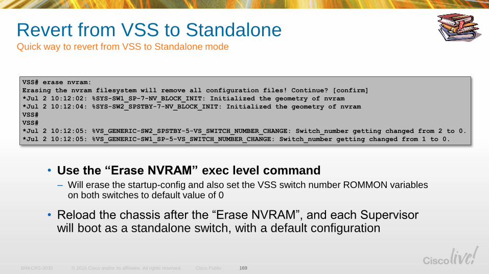
© 2015 Cisco and/or its affiliates. All rights reserved.BRKCRS-3035 Cisco Public
Revert from VSS to StandaloneQuick way to revert from VSS to Standalone mode
169
• Use the “Erase NVRAM” exec level command– Will erase the startup-config and also set the VSS switch number ROMMON variables
on both switches to default value of 0
• Reload the chassis after the “Erase NVRAM”, and each Supervisor will boot as a standalone switch, with a default configuration
VSS# erase nvram:
Erasing the nvram filesystem will remove all configuration files! Continue? [confirm]
*Jul 2 10:12:02: %SYS-SW1_SP-7-NV_BLOCK_INIT: Initialized the geometry of nvram
*Jul 2 10:12:04: %SYS-SW2_SPSTBY-7-NV_BLOCK_INIT: Initialized the geometry of nvram
VSS#
VSS#
*Jul 2 10:12:05: %VS_GENERIC-SW2_SPSTBY-5-VS_SWITCH_NUMBER_CHANGE: Switch_number getting changed from 2 to 0.
*Jul 2 10:12:05: %VS_GENERIC-SW1_SP-5-VS_SWITCH_NUMBER_CHANGE: Switch_number getting changed from 1 to 0.
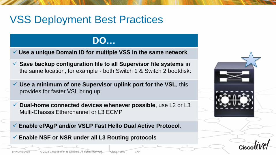
© 2015 Cisco and/or its affiliates. All rights reserved.BRKCRS-3035 Cisco Public
VSS Deployment Best Practices
170
DO… Use a unique Domain ID for multiple VSS in the same network
Save backup configuration file to all Supervisor file systems in
the same location, for example - both Switch 1 & Switch 2 bootdisk:
Use a minimum of one Supervisor uplink port for the VSL, this
provides for faster VSL bring up.
Dual-home connected devices whenever possible, use L2 or L3
Multi-Chassis Etherchannel or L3 ECMP
Enable ePAgP and/or VSLP Fast Hello Dual Active Protocol.
Enable NSF or NSR under all L3 Routing protocols
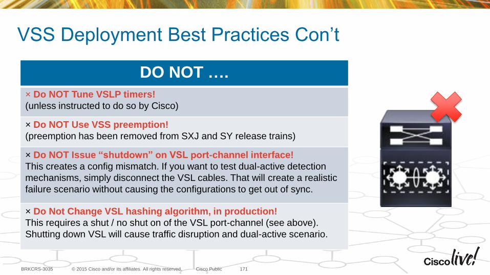
© 2015 Cisco and/or its affiliates. All rights reserved.BRKCRS-3035 Cisco Public
VSS Deployment Best Practices Con’t
171
DO NOT ….
× Do NOT Tune VSLP timers!
(unless instructed to do so by Cisco)
× Do NOT Use VSS preemption!
(preemption has been removed from SXJ and SY release trains)
× Do NOT Issue “shutdown” on VSL port-channel interface!
This creates a config mismatch. If you want to test dual-active detection
mechanisms, simply disconnect the VSL cables. That will create a realistic
failure scenario without causing the configurations to get out of sync.
× Do Not Change VSL hashing algorithm, in production!
This requires a shut / no shut on of the VSL port-channel (see above).
Shutting down VSL will cause traffic disruption and dual-active scenario.
Summary
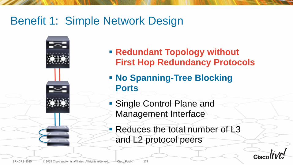
© 2015 Cisco and/or its affiliates. All rights reserved.BRKCRS-3035 Cisco Public
Redundant Topology without First Hop Redundancy Protocols
No Spanning-Tree Blocking Ports
Single Control Plane and Management Interface
Reduces the total number of L3 and L2 protocol peers
Benefit 1: Simple Network Design
173
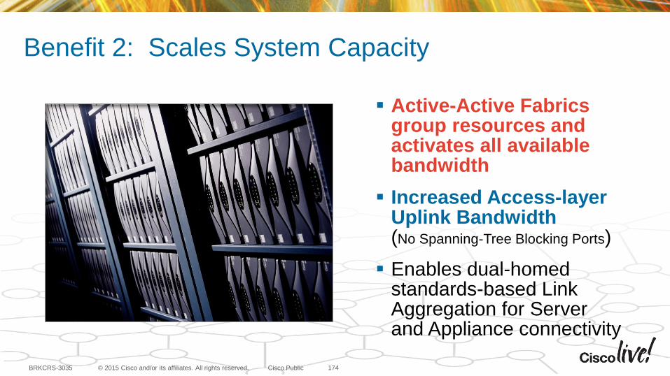
© 2015 Cisco and/or its affiliates. All rights reserved.BRKCRS-3035 Cisco Public
Active-Active Fabrics group resources and activates all available bandwidth
Increased Access-layer Uplink Bandwidth (No Spanning-Tree Blocking Ports)
Enables dual-homed standards-based Link Aggregation for Server and Appliance connectivity
Benefit 2: Scales System Capacity
174
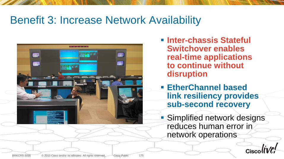
© 2015 Cisco and/or its affiliates. All rights reserved.BRKCRS-3035 Cisco Public
Benefit 3: Increase Network Availability
175
Inter-chassis StatefulSwitchover enables real-time applications to continue without disruption
EtherChannel based link resiliency provides sub-second recovery
Simplified network designs reduces human error in network operations
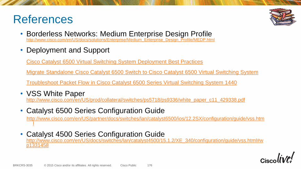
© 2015 Cisco and/or its affiliates. All rights reserved.BRKCRS-3035 Cisco Public
References• Borderless Networks: Medium Enterprise Design Profile
http://www.cisco.com/en/US/docs/solutions/Enterprise/Medium_Enterprise_Design_Profile/MEDP.html
• Deployment and Support
Cisco Catalyst 6500 Virtual Switching System Deployment Best Practices
Migrate Standalone Cisco Catalyst 6500 Switch to Cisco Catalyst 6500 Virtual Switching System
Troubleshoot Packet Flow in Cisco Catalyst 6500 Series Virtual Switching System 1440
• VSS White Paperhttp://www.cisco.com/en/US/prod/collateral/switches/ps5718/ps9336/white_paper_c11_429338.pdf
• Catalyst 6500 Series Configuration Guidehttp://www.cisco.com/en/US/partner/docs/switches/lan/catalyst6500/ios/12.2SX/configuration/guide/vss.htm
l
• Catalyst 4500 Series Configuration Guidehttp://www.cisco.com/en/US/docs/switches/lan/catalyst4500/15.1.2/XE_340/configuration/guide/vss.html#wp1331458
176
© 2015 Cisco and/or its affiliates. All rights reserved.BRKCRS-3035 Cisco Public
Call to Action
• Visit the World of Solutions for
– Cisco Campus
– Walk in Labs
– Technical Solution Clinics
• Meet the Engineer
• Lunch time Table Topics
• DevNet zone related labs and sessions
• Recommended Reading: for reading material and further resources for this session, please visit www.pearson-books.com/CLMilan2015
177
© 2015 Cisco and/or its affiliates. All rights reserved.BRKCRS-3035 Cisco Public
Complete Your Online Session Evaluation
• Please complete your online sessionevaluations after each session.Complete 4 session evaluations& the Overall Conference Evaluation(available from Thursday)to receive your Cisco Live T-shirt.
• All surveys can be completed viathe Cisco Live Mobile App or theCommunication Stations
178